VSI X.25 for OpenVMS Configuration Guide
- Software Version:
- VSI X.25 for OpenVMS Version 2.1
- Operating System and Version:
- VSI OpenVMS IA-64 Version 8.4-1H1 or higher
VSI OpenVMS Alpha Version 8.4-2L1 or higher
Preface
This guide explains how to configure VSI X.25 for OpenVMS.
1. About VSI
VMS Software, Inc. (VSI) is an independent software company licensed by Hewlett Packard Enterprise to develop and support the OpenVMS operating system.
2. Intended Audience
This guide is intended for use by anyone who is configuring an X.25 system for the first time, or is reconfiguring an existing system.
Local Area Networks (LANs)
Wide Area Networks (WANs)
X.25 communications
The configuration program can be run in two modes: BASIC mode, and ADVANCED mode. To run the utility in ADVANCED mode, you should have a good understanding of management entities, and the relationship between those entities. Such information is given in the VSI X.25 for OpenVMS Management Guide.
3. Document Structure
Chapter 1, "Introduction" outlines the modes in which the configuration program can be used to configure a system and explains the areas you need to consider before you run the utility.
Chapter 2, "Using the Configuration Program" details how to run the utility and how to access help information, and provides details of the keys that can be used while running the configuration program.
Chapter 3, "Overview of BASIC Mode" provides an overview of running the configuration program in BASIC mode and describes each of the available configuration sections.
Chapter 4, "Required Configuration Data" details the data that you need to obtain before running the utility.
Chapter 5, "Flowcharts and Associated Notes" provides flowcharts to illustrate the flow of data entry and data required within each section. Each flowchart is accompanied by a set of associated notes.
Chapter 6, "Overview of ADVANCED Mode" provides an overview of running the configuration program in ADVANCED mode and describes each of the available configuration sections.
Chapter 7, "Required Configuration Data" details the data that you need to obtain before running the utility.
Chapter 8, "Flowcharts and Associated Notes" provides flowcharts to illustrate the flow of data entry and data required within each section. Each flowchart is accompanied by a set of associated notes.
Chapter 9, "Verifying the Configuration" explains how to test your configuration using the Configuration Test Procedure (CTP).
Chapter 10, "Modifying the Configuration" explains how to modify an existing configuration, that is, to reconfigure a system.
Appendix A, "Values Specific to Your Configuration" contains a series of blank forms in which you can write the values of configuration parameters specific to your system.
Appendix C, "Example Configurations" contains two sample configurations with the configuration files produced by the configuration program.
Appendix D, "Characteristic Values of the Default and OSI Transport Templates" lists the characteristic values of the parameters in the "Default" and "OSI Transport" templates.
Appendix E, "Configuration Files – Location and Use" lists the location and use of each of the configuration files either created as a result of running the configuration program in BASIC and ADVANCED modes or supplied with the product.
4. OpenVMS Documentation
The full VSI OpenVMS documentation set can be found on the VMS Software Documentation webpage at https://docs.vmssoftware.com.
5. VSI Encourages Your Comments
You may send comments or suggestions regarding this manual or any VSI document by sending electronic mail to the following Internet address: <docinfo@vmssoftware.com>. Users who have VSI OpenVMS support contracts through VSI can contact <support@vmssoftware.com> for help with this product.
6. Terminology
|
VAX P.S.I. |
X.25 for OpenVMS |
|---|---|
|
VAX P.S.I. |
X.25 for OpenVMS VAX |
|
Access system |
X.25 Client system |
|
Native system |
X.25 Direct Connect system |
|
Multihost system |
X.25 Connector system |
|
Gateway system |
X.25 Connector system |
|
Client system |
A client system of an X.25 Connector system (and therefore a client of the X25 Server management module on the X.25 Connector system.) |
|
Relay Client system |
A client system of an X.25 Relay system (and therefore a client of the X25 Relay management module on the X.25 Relay system.) |
|
Relay–Client |
A shorthand term for an X25 RELAY CLIENT management entity on an X.25 Relay system that contains management information about an actual Relay Client system. |
|
Relay system |
An X.25 Direct Connect or Connector system with the X.25 Relay module enabled. |
|
Server Client system |
Another term for a Client system. |
|
Server–Client |
A shorthand term for an X25 SERVER CLIENT management entity on an X.25 Connector system that contains management information about one or more actual X.25 Client systems. |
For more information about clients, servers, and relays in X.25 for OpenVMS, refer to the VSI X.25 for OpenVMS Configuration manual and the VSI X.25 for OpenVMS Management Guide.
7. Conventions
VSI OpenVMS for Integrity servers
OpenVMS IA-64
I64
All three names — the longer form and the two abbreviated forms — refer to the version of the OpenVMS operating system that runs on the Intel ® Itanium ® architecture.
|
Convention |
Meaning |
|---|---|
|
UPPERCASE and lowercase |
The OpenVMS operating system does not differentiate between lowercase and uppercase characters. Literal strings that appear in text, examples, syntax descriptions, and function descriptions can be enteredusing uppercase characters, lowercase characters, or a combination of both. In running text, uppercase characters indicate OpenVMS DCL commands and command qualifiers; Network Control Language (NCL) commands and command parameters; other product–specific commands and command parameters; network management entities; OpenVMS system logical names; and OpenVMS system service calls, parameters, and item codes. Leading uppercase characters, such as Protocol State, indicate management entity characteristics and management entity event names. Leading uppercase characters are also used for the top-level management entities known as modules. |
|
This typeface is used in interactive and code examples to indicate system output. In running text, this typeface is used to indicate the exact name of a device, directory, or file; the name of an instance of a network management entity; or an example value assigned to a DCL qualifier or NCL command parameter. |
user input
|
In interactive examples, user input is shown in
bold
print. |
|
italic text |
Italic text indicates variables or book names. Variables include information that varies in system input and output. In discussions of event messages, italic text indicates a possible value of an event argument. |
|
bold text |
Bold text indicates an important term, or important information. |
|
(#### ) |
In a command definition, parenthesis indicate that you must enclose the options in parenthesis if you choose more than one. Separate the options using commas. |
|
In a command definition, braces are used to enclose sets of values. The braces are a required part of the command syntax. | |
|
[####] |
In a command definition, square brackets are used to enclose parts of the command that are optional. You can choose one, none, or all of the options. The brackets are not part of the command syntax. However, brackets are a required syntax element when specifying a directory name in an OpenVMS file specification. |
|
Enter |
A boxed symbol indicates that you must press a key on the terminal; for example, Enter indicates that you press the Enter key. |
|
Ctrl/x |
The symbol Ctrl/x indicates that you hold down the key labeled CTRL while you press another key, for example, Ctrl C or Ctrl O. |
|
$ |
In this manual, a dollar sign ($) is used to represent the default OpenVMS user prompt. |
Chapter 1. Introduction
VSI X.25 for OpenVMS needs to be configured before your system can communicate with remote systems via a Packet Switching Data Network (PSDN).
This chapter provides an overview of the configuration process, and outlines the steps you should take before running the configuration program.
1.1. Configuration Overview
After installing X.25 for OpenVMS it must be configured specifically for your system. X.25 for OpenVMS provides a
configuration program that enables you to define configuration parameter values specific
to your system. The program generates a script containing the Network Control Language
(NCL) commands necessary to set up your X.25 configuration. When invoked, the X.25
startup procedure (X25$STARTUP.COM) executes the NCL script.
An NCL script is a series of NCL commands, each of which relates to a specific aspect of configuration. To make each script more readable, the NCL commands are interspersed with comments that indicate what actions the subsequent NCL commands perform. Two example NCL scripts are shown in Appendix C, "Example Configurations".
1.2. Configuration Program Modes
X25$CONFIGURE.COM,
can be run in one of two modes to configure a system:BASIC mode, which is used to create a basic working configuration. This mode provides a mechanism for configuring a system, without the need to have knowledge of, or understand, the X.25 management entities.
ADVANCED mode, which is used to create more complex working configurations. This mode of operation requires you to have a good understanding and working knowledge of the X.25 management entities.
1.2.1. Selecting the Configuration Mode
The configuration mode you need to choose depends on the type of X.25 configuration you want to generate.
One DTE connected to a PSDN, with X.25 Mail and/or X.29 operating over that connection. The use of PVCs and DECnet-Plus OSI Transport services are also supported.
One or more DTEs configured to run over a single LAN device, with X.25 Mail and/or X.29 operating over those connections. The use of PVCs and DECnet-Plus OSI Transport services are also supported.
One X.25 Client system connected to one or more PSDNs via one or more X.25 Connector systems, with X.25 Mail and/or X.29 operating over that connection.
If one of these configurations satisfies your X.25 requirements, then the BASIC mode will be sufficient to configure your system.
More than one connection to a PSDN
Connections to a Local Area Network over more than one LAN device
Both a WAN connection and a LAN connection
X.25 over TCP/IP (XOT) DTEs
More than one X.25 Client system
Your own X.25 or X.29 applications to service incoming X.25 calls
Closed User Group (CUG) support
X.25 Relay support
X.25 Server support
Note that any configuration data entered using the BASIC mode is available when the configuration program is subsequently run using the ADVANCED mode. Therefore, you can create a simple configuration using BASIC mode, and then add to it by running the ADVANCED mode (using the "Modify an existing configuration script" option).
1.3. Changing Your Configuration
To allow flexibility, configurations need to be modified on either a temporary or permanent basis.
X.25 for OpenVMS provides a number of methods to modify an existing configuration. These methods are detailed in Chapter 10, "Modifying the Configuration".
1.4. Obtaining Help
A comprehensive Help facility is available in both BASIC and ADVANCED mode and can be used if further information is required while running the configuration program. Full details of the help facility available in each mode are given in Chapter 2, "Using the Configuration Program".
1.5. Steps in Configuring Your System
Plan your configuration. As part of this task you should take note of the information given in Section 1.6, ''Configuration Considerations''.
Time spent planning your configuration will obviate the need to perform major or constant reconfigurations at later stages.
Record the information you will need during the configuration program. Tables are provided in Appendix A, "Values Specific to Your Configuration" for this purpose.
For the BASIC mode, use Chapter 3, "Overview of BASIC Mode" and Chapter 4, "Required Configuration Data" to determine the information required.
For the ADVANCED mode, use Chapter 6, "Overview of ADVANCED Mode" and Chapter 7, "Required Configuration Data" to determine the information required.
Run the configuration program in either BASIC mode or ADVANCED mode (refer initially to Chapter 2, "Using the Configuration Program" and then to Chapter 3, "Overview of BASIC Mode" (BASIC mode) or to Chapter 6, "Overview of ADVANCED Mode" (ADVANCED mode)).
Test your configuration. Refer to Chapter 9, "Verifying the Configuration".
1.6. Configuration Considerations
This section introduces aspects of your proposed configuration that you need to consider before you run the configuration program.
1.6.1. Required Licenses
Systems running X.25 for OpenVMS have direct access to one or more PSDNs conforming to CCITT recommendation X.25 and to ISO standards 7776 and 8208, or to communicate with another node on the LAN via LLC2.
In addition, X.25 for OpenVMS allows OpenVMS systems on a DECnet–Plus network to connect to PSDNs through one or more X.25 Connector nodes. This enables communication between the X.25 for OpenVMS system and a remote DTE.
DECnet–Plus
X.25 for OpenVMS
Chapter 2. Using the Configuration Program
2.1. Introduction
This chapter explains how to invoke the VSI X.25 for OpenVMS configuration program and provides details on the facilities and keys that are available to help you to complete the configuration.
Note
Throughout this and subsequent chapters, reference is made to the keys available on a VT200 (or higher) keyboard.
Refer to Section 2.3.4, ''Keys Used in the Configuration Program'' for keys that are supported on this and other terminals.
2.2. Invoking the Configuration Program
Log in to a suitably privileged account. You need the SYSPRV privilege to run the configuration program. In addition, you will need the CMKRNL, DETACH, NETMBX, OPER, PRMMBX, and TMPMBX privileges as well as the NET$MANAGE and NET$EXAMINE rights identifiers to invoke
SYS$STARTUP:X25$STARTUP.COMto start X.25 for OpenVMS.Invoke the configuration program in either BASIC or ADVANCED mode.
To invoke the configuration program in BASIC mode, enter the following command:$@sys$startup:x25$configure basicTo invoke the configuration program in ADVANCED mode, enter one of the following commands:$@sys$startup:x25$configure advanced$@sys$startup:x25$configure
WANDD$CONFIGURE.COM) is run. This procedure
allows you to configure the synchronous device drivers to permit direct connection to a wide area
network via a serial port.If WANDD has not been configured, you are prompted whether to configure the device drivers.
If WANDD has been configured, you are prompted whether to reconfigure the device drivers.
In both cases, you are then prompted whether to load the WANDD management software and the auto–configurable synchronous devices.
If you select to load the auto–configurable synchronous devices, you are further prompted whether to configure the built–in serial port as a synchronous device.
An example showing these prompts and example responses is given below.
$ @sys$startup:x25$configure
  Configuring WANDD... [’?’ for HELP]
%WANDD$CONFIGURE-I-WANDDNOTCONFIG, WANDD has not been configured.
Configure WANDD? [YES] Return
Load WANDD? [YES] Return
  All installed synchronous devices will be automatically
  configured. However, the built--in serial port will only
  be configured at your request.
Configure built-in serial port as synchronous? [YES] Return
! SYS$STARTUP:WANDD$CONFIG.DAT
! Created by SYSTEM on 10-FEB-1994 14:28:09.02
!
load_wandd     YES
load_zrdriver  YES
!
! End of SYS$STARTUP:WANDD$CONFIG.DAT
Are you satisfied with your answers? [YES] Return
%NET-I-LOADED, executive image X25$KERNEL_RTL.EXE loaded
%NET-I-LOADED, executive image X25$MEL.EXE loaded
%NET-I-LOADED, executive image X25$L2.EXE loaded
%NET-I-LOADED, executive image X25$L1.EXE loaded
%SYSMAN-I-OUTPUT, command execution on node SPTENZ
%IOGEN-I-PREFIX, searching for ICBM with prefix SYS$
%IOGEN-I-PREFIX, searching for ICBM with prefix X25$
%IOGEN-I-SCSIPOLL, scanning for devices through SCSI port PKA0
%IOGEN-I-SCSIPOLL, scanning for devices through SCSI port PKB0
%RUN-S-PROC_ID, identification of created process is 00000092
  Available Synchronous Communication Ports:
    1. ZRA0 - SSCC-0-0
 Press RETURN to continue...
Once WANDD$CONFIGURE has been run, the initial screen of the X.25 configuration
program is displayed.
2.3. Common Operations
The configuration program consists of a number of sections, each corresponding to a logical group of information.
Most sections are optional, that is you do not have to enter information unless you want to.
Such sections begin with a question in the form: Do you want to set up
X?
If you respond "Yes" to the prompt, the rest of that section is presented to allow you to complete it. If you respond "No" to the prompt, the next new section is presented. You can decide at a later stage to complete any section that you bypass (refer to Section 2.3.5, ''Accessing the Options Menu'').
Each section commences with a screen of introductory information and is followed by one or more screens on which you can enter data. Each data entry screen contains one or more fields in which you can enter data. Some fields are mandatory, others are optional.
2.3.1. Entering Information
By selecting an option from a displayed menu. To select an option, move the cursor over that option using the arrow keys (refer to Section 2.3.4, ''Keys Used in the Configuration Program'') and then press Return.
By entering data in a field. To enter data, move to the field (refer to Section 2.3.4, ''Keys Used in the Configuration Program''), key in the data, and then press Return.
When you have entered all the required information on a screen, a new screen is automatically displayed. You cannot move to a new screen until you have completed all the mandatory fields on the current screen.
2.3.1.1. Horizontal Scrolling
Usually, when you enter data into a field, all the data you enter is displayed. However, in some cases, the maximum number of data characters you are allowed to enter is greater than the length of the field displayed on the screen. In such cases, the entered data will scroll horizontally when you have entered the maximum number of characters that can be displayed.
Note that horizontal scrolling works only if the data entry screen is in Insert mode. Refer to Section 2.3.1.2, ''Data Entry Mode''.
2.3.1.2. Data Entry Mode
By default, each data entry screen is invoked in Overstrike mode. In this mode, any characters entered overwrite any characters currently displayed in the data entry field. If required, a data entry screen can be placed in Insert mode. In this mode, any characters entered are inserted into the characters currently displayed; any previously entered characters are moved to the right. To change from one mode to the other, press Ctrl/A. The current mode is displayed in the upper right–hand corner of the data entry screen.
2.3.2. Moving Within a Section
To move backwards within a section to a previous screen, press Prev Screen. You are allowed to move backwards within a section whether you have completed all the screens in that section or not. However, you can move backwards only as far as the first screen of the section.
If you have moved back to look at completed screens, you can move forward again by pressing Next Screen. You can only move forward until you reach an incomplete screen. The mandatory fields on the incomplete screen must then be completed before moving on.
2.3.3. Moving Between Sections
The methods available for moving between sections depend on whether you are running the configuration program in BASIC or ADVANCED mode and whether you are creating or modifying a configuration.
BASIC Mode
When creating a configuration, the next uncompleted section is displayed automatically when the current section has been completed.
When the last section (the NCL Script Section) is displayed, you are prompted whether to create the NCL script or review and modify the information you have entered. Entering "No" to this prompt displays the Sections Menu from which you can select a section to be reviewed or modified.
When modifying a configuration, a specific section can be selected from the Sections Menu. The Sections Menu is displayed automatically after you select the type of X.25 connection required, or can be accessed from the Options Menu of the current section by selecting the option "Go to Sections Menu" (refer to Section 2.3.5, ''Accessing the Options Menu'').
ADVANCED Mode
To move to the next uncompleted section, select the option "Continue to a new section".
To move to a previously completed section, select the option "Go to Sections Menu".
Full details of the Options Menu are provided in Section 2.3.5, ''Accessing the Options Menu''.
When modifying a configuration, a specific section can be selected from the Sections Menu. The Sections Menu is displayed automatically after you select the option "Modify an existing configuration script", or it can be accessed from the Options Menu of the current section by selecting the option "Go to Sections Menu" (refer to Section 2.3.5, ''Accessing the Options Menu'').
2.3.4. Keys Used in the Configuration Program
Table 2.1, ''Available Keys'' lists the keys you can use when running the configuration program in either BASIC or ADVANCED mode.
Note that if your terminal does not support cursor keys, you cannot move between fields and therefore you will not be able to run the configuration procedure.
To use the cursor keys, you must ensure that the terminal type is set correctly so that it reflects the terminal being emulated.
$ SET TERMINAL/DEVICE=terminal-typeVT300,
VT200, and so on.Note
VT320. To set the correct
terminal type:Display the Options pull–down menu.
Select the General … option.
Select
VT300 Mode, 7–Bit Controland Terminal IDVT320 ID.Select OK.
|
DEC Terminal (VT200 or higher) Keys |
Function |
|---|---|
|
Movement Keys | |
|
UP and DOWN arrow keys |
Moves cursor between fields |
|
LEFT and RIGHT arrow keys |
Moves cursor within a field |
|
Prev Screen or Ctrl/P |
Takes you to the previous screen in the current section |
|
Next Screen or Ctrl/N |
Takes you to the next screen in the current section |
|
F12 or Ctrl/E |
Moves cursor to end of input field |
|
Ctrl/H |
Moves cursor to start of input field |
|
Edit Keys | |
|
Return, Select, or Enter |
Enters/Selects a value |
|
Remove or Ctrl-U |
Deletes all characters from a field |
|
Delete |
Deletes previous character |
|
Action Keys | |
|
Help or Ctrl/K |
Provides help on the current field |
|
F9 or Ctrl/R | |
|
F10 or Ctrl/Z |
Return to Procedure Help menu |
|
F8 or Ctrl/Z |
Quit |
|
F14 or Ctrl/A |
Toggle Insert/Overstrike Mode |
|
Ctrl/W |
Redraw screen |
2.3.5. Accessing the Options Menu
You review or modify a section in BASIC mode.
You complete the last data entry screen of a section while creating or modifying a section in ADVANCED mode.
where X is the item you created in that section.
Continue to a new section
Add a Remote DTE Class
Modify a Remote DTE Class
Delete a Remote DTE Class
Go to Sections Menu
To perform an action, select one of the options on the Options Menu. The options have the following meanings:
Continue to a new section
Choose this option when you have finished entering or amending information in the current section. The configuration program then displays the first screen in the next uncompleted section.
Add an X
Choose this option to add another item to the current section.
Modify an X
Choose this option to modify some or all of the information previously entered about an item.
Delete an X
Choose this option to delete an item in the current section.
Go to Sections Menu
Choose this option to display the Sections Menu. Selecting a section from the Sections Menu will display the Options Menu of that section.
2.4. Obtaining Help
You can get help at any time during the program by pressing the Help key. The level of help you receive depends on where the cursor is positioned when you press the Help key. Subsections Section 2.4.1, ''Obtaining Help on a Specific Field or Menu Choice'', Section 2.4.2, ''Obtaining General Help'', and Section 2.4.3, ''Obtaining Help on the Program'' detail each level of help.
2.4.1. Obtaining Help on a Specific Field or Menu Choice
If you press Help while the cursor is on a particular field or menu choice, lines of text will appear near the bottom of the screen. The text tells you what sort of value is expected in that field, or what the implications are of making that choice if further help is available.
If you press Help again and further help is available, the screen is replaced by further information on that field or menu choice. Press F10 to leave Help and return to the screen from which you pressed Help originally.
2.4.2. Obtaining General Help
If you press Help while on any of the introductory screens, the screen will be replaced by general information on that section. For example, pressing Help while on the NCL introduction screen brings up general information on NCL script and NCL commands.
2.4.3. Obtaining Help on the Program
You can get help on the configuration program (for example, what keys you can use, how to navigate between screens) by pressing Help while you are on any other Help screen. A list of topics is presented from which you can select the item of interest. Press F10 to leave Help and return to the screen from which you pressed Help originally.
2.5. Creating the Configuration File
The final section in the configuration program, NCL Script, allows you to initiate the generation of the relevant NCL script for the configuration file from the information held in the configuration database.
Select the option "NCL Script" option from the Sections Menu.
Complete the next to last section and select the option "Continue to a new section" option from the Options Menu.
Do you want to modify your answers?
To create the NCL script, enter NO in response to the prompt.
If you want to return to any of the completed sections and modify the existing data before creating the NCL script, enter YES in response to the prompt. The Sections Menu is redisplayed.
To quit from the configuration program without generating an NCL script, refer to Section 2.6, ''Quitting from the Configuration Program''.
During the creation of the NCL script a number of messages are displayed on the screen and a number of system files are created:
SYS$SYSTEM:X25$SECURITY_IDENTIFIERS.COM | |
|
This command procedure creates the rights identifiers required based on the security information you enter. This procedure can be run prior to leaving the configurator. If the command procedure is created, you are prompted whether to run the procedure. | |
SYS$SYSTEM:MODPARAMS.DAT | |
|
This file is modified only if you have configured X.25 Client and the number of session control connections is changed. It contains values for a number of system parameters, based on the number of session control connections specified. Refer to Section 2.8, ''Post–Configuration Tasks''. | |
SYS$STARTUP:X25$SESSION_STARTUP.COM | |
|
This command procedure defines the process parameters for the X.25 for OpenVMS Session Control Process. It is run when X.25 for OpenVMS is invoked. | |
SYS$STARTUP:X25$APPL_STARTUP.COM | |
|
This command procedure defines the process parameters for the X.25 for OpenVMS Application Daemon
Process. It is run when X.25 for OpenVMS is invoked. If the file is not found during startup,
| |
SYS$STARTUP:X25$MAIL_SETUP.COM | |
|
This command procedure creates the user account in which X.25 Mail will run. It is created only if the X.25 Utilities Section is completed and is run before you exit the configuration program. | |
Finally, the Main Menu is redisplayed to allow you to exit the configuration program.
If, for some reason, the program cannot create the NCL script, an error message is displayed at the foot of the screen. This may occur if, for example, a file cannot be created due to incorrect permissions. You must correct the problem before making a further attempt to create the NCL script.
Press Return to display the Main Menu.
Select the option "Exit this program".
Rectify the error.
Re–run the configuration program.
Select the option "Modify an existing configuration script".
Access the NCL Section from the Sections Menu.
Select to create the NCL script.
If the course of action detailed in steps 1 to 7 does not rectify the problem, please report the problem to VSI support.
2.6. Quitting from the Configuration Program
Caution
Quitting from the configuration program deletes all information entered since the NCL script was last created or since the configuration data was last saved. This action should therefore be performed only if you do not want to retain the entered data.
Press F8.
A warning message is displayed and you are prompted to confirm that you want to quit the configuration program.
To quit the program, enter YES. The system prompt is redisplayed.
To return to the program, enter NO. The screen from which you chose to quit the configuration program is redisplayed.
2.7. Leaving the Configuration Program
Once the configuration program has created the configuration file containing the NCL scripts, the Main Menu is redisplayed.
To leave the configuration program, select the option "Exit this program".
2.8. Post–Configuration Tasks
- If you changed the number of session connections, run the Autogen utility and reboot your system. For example, these actions can be performed by issuing the command:
$ @SYS$UPDATE:AUTOGEN SAVPARAMS REBOOT FEEDBACKFurther details about configuring the number of session control connections are given in Section 8.6, ''Session Connections''.
Ensure that the NSP attributes Maximum Transport Connections and Maximum Remote NSAPs are large enough to support the number of session connections required. The default values of these attributes are 200 and 201 respectively.
If you have run the configurator in BASIC mode, grant the rights identifier X25_OUTGOING_ALL to all users and processes that are to be permitted to make outgoing calls.
For compatibility with VAX P.S.I., a number of logicals have been provided (but commented out) in
SYS$STARTUP:X25$STARTUP.COM. Details of the available logicals are provided in the VSI X.25 for OpenVMS Management Guide. To use these logicals, editX25$STARTUP.COMand remove the comment characters that precede the logicals.Shut down any existing X.25 for OpenVMS configuration by running the command procedure
SYS$STARTUP:X25$SHUTDOWN.COM.Run the command procedure
SYS$STARTUP:X25$STARTUP.COMto execute the NCL script.
Chapter 3. Overview of BASIC Mode
3.1. Introduction to the BASIC Mode
The BASIC mode of the configuration program allows you to configure a working X.25 system without needing to have any knowledge of the X.25 management entities and the relationship between such entities.
To use the BASIC mode, you only need to have a knowledge of the network components of your system and a basic knowledge of X.25. If you are new to X.25 and you have not already done so, you are encouraged to read the VSI DECnet-Plus for OpenVMS Introduction and User's Guide before using the configuration program.
3.2. Configuration Program Structure
You do not need to complete each of the available sections; you only need to complete the sections relevant to the configuration that you want to set up. For example, you might only want to configure the X.25 Connection as an X.25 Client and configure security. Note that only one of the subsections in the first section can be completed.
The data required to complete a configuration depends on the sections to be completed. Details explaining the purpose of each section are given in Section 3.3, ''Configuration Sections'' and full details about the data required to complete each section are given in Chapter 4, "Required Configuration Data".
3.3. Configuration Sections
X.25 Connection
X.25 over Wide Area Network
This section allows you to enter details about an X.25 network to which your system is attached. You must provide the profilename, DTE address, outgoing and incoming channel number ranges, and synchronous line associated with the DTE connected to the named network.
X.25 over Local Area Network
This section allows you to enter details about each of the LAN-based remote hosts you want to access from this system. You must select a LAN device to be used by all the LAN remote hosts. For each remote host you name, you must provide the DTE address and remote Media Access Control (MAC) address associated with each DTE connected to the LAN. A profile does not need to be specified as it is set to ISO8881.
This section allows you to enter details about an X.25 network (Remote DTE Class) to which your system is attached and the X.25 Connector nodes used by the specified network (Remote DTE Class) to access the PSDN.
PVCs
This section allows you to define one or more Permanent Virtual Circuits (PVCs). Your PSDN subscription will determine whether you are permitted to set up any PVCs. For each PVC you name you must specify a channel number.
This section is not presented if you configure your system as an X.25 Client.
Incoming Call Security
Note
VSI strongly recommends that you set up incoming security to protect your system from unauthorized use.
Allow all incoming access
Allow no incoming access
Restricted incoming access
If restricted incoming access is selected, you must enter remote DTE addresses for each remote DTE that needs to make an incoming call. The remote DTE addresses must be categorized and entered in one of two Access Level categories: Remote Charge or All.
X.29 Support
This section allows you to configure X.29 support on your system so that remote users can access the local system via an X.25 network and local users can access a remote system via an X.25 network. If required, you can specify a Network User Identity (NUI) to identify the party that is to pay for each outgoing call.
X.25 Mail
This section allows you to include X.25 Mail support on your system so that users can send mail to, and receive mail from, other systems that implement the Mail-11 protocol over X.25.
Chapter 4. Required Configuration Data
4.1. Overview
This chapter details the information you will need to provide while running the configuration program in BASIC mode.
Tables 4.1 to 4.6 list all the information you willrequire during the configuration. You should write down the configuration parameter values specific to your system in Appendix A, "Values Specific to Your Configuration" (which provides a series of blank forms) and refer to that Appendix when you run the configuration program.
|
Information required |
Form in which it is required |
Where to find information |
Default value or setting |
|---|---|---|---|
|
Profile name |
– |
Refer to Section 1.6.2, ''Network Profiles'' |
– |
|
X.25 address |
Max 15 digits |
PSDN subscription information |
– |
|
Synchronous line name |
Characters |
Choose from lines determined by program |
– |
|
Incoming logical channel ranges |
Range of numbers |
PSDN subscription information |
{[1..4095]} |
|
Outgoing logical channel ranges |
Range of numbers |
PSDN subscription information |
{[1..4095]} |
|
Information required |
Form in which it is required |
Where to find information |
Default value or setting |
|---|---|---|---|
|
LAN device |
Characters |
Choose from devices determined by program |
– |
|
X.25 DTE address |
Max 15 digits |
You supply |
– |
|
LAN remote host name |
Max 32 characters |
You supply |
– |
|
Remote MAC address |
LAN hardware address |
Remote system |
– |
|
Incoming logical channel ranges |
Range of numbers |
PSDN subscription information |
{[1..4095]} |
|
Outgoing logical channel ranges |
Range of numbers |
PSDN subscription information |
{[1..4095]} |
|
Information required |
Form in which it is required |
Where to find information |
Default value or setting |
|---|---|---|---|
|
Security option |
Allow all incoming access Allow no incoming access Restrict incoming access |
Choose one of the available options |
– |
|
If you select "Restrict incoming access" you must enter the following additional information: | |||
|
DTE addresses of systems that can call this system only if they pay for the call |
Max 15 digits. Can be a full DTE address or a Remote Address Prefix (RAP) |
You supply |
– |
|
DTE addresses of systems that can call this system irrespective of who pays for the call |
Max 15 digits. Can be a full DTE address or a Remote Address Prefix (RAP) |
You supply |
– |
|
Information required |
Form in which it is required |
Where to find information |
Default value or setting |
|---|---|---|---|
|
X.29 network user identity |
Octet string |
You supply |
– |
Chapter 5. Flowcharts and Associated Notes
This chapter contains flowcharts illustrating each section presented when the BASIC mode of the configuration program is run,together with notes about each section.
5.1. Introduction
Figure 5.1, ''Introduction'' illustrates the Introduction Section.
The Introduction Section provides you with options to create a new X.25 for OpenVMS configuration, modify an existing configuration, or exit from the program. These options are detailed more fully in subsections 5.1.1, 5.1.2, and 5.1.3 respectively.
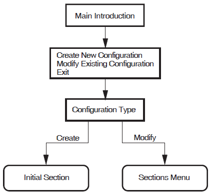
5.1.1. Creating a New Configuration
Select the option "Create a new configuration script".
The configuration program displays the Configuration Type Section. This section displays the types of X.25 systems that you can configure. The choices are:- X.25 over Wide Area Network
- X.25 over Local Area Network
- X.25 Client
Select the type of system you want to configure. You can select only one of the available choices.
The configuration program then displays the configuration section associated with the option selected.
The section displayed is the first in a series of sections that can be completed. You do not have to complete every section, only those that present functions that you want to configure. When the current section has been completed, you are given the opportunity to amend that section or to move on to another section. In some sections you are given the opportunity to move on to the next section without completing the current section.
Complete the current section or select to move on to the next section.
Repeat step 2 for each of the sections. To create a configuration script you must complete the NCL Script Section.
5.1.2. Modifying an Existing Configuration
Select the option "Modify an existing configuration script".
The Configuration Type screen is displayed with the current X.25 connection type highlighted.
- Select the type of X.25 connection you want to configure. You can select only one of the available choices. The next action depends on whether you select to retain the existing type of X.25 connection or to create a different type:
If you select to retain the existing type, the Sections Menu is displayed. Continue at step 3.
If you select to create a different type, you will be prompted to confirm that you want to delete the existing X.25 connection information. If you choose to delete the existing information, the section associated with the selected (new)configuration type is displayed and must be completed. Once completed, the Sections Menu is displayed. Continue at step 3.
- The Sections Menu presents the sections that can be modified. These are:
X.25 Connection
PVCs
Incoming Call Security
X.29 Support
X.25 Mail
NCL Script
Note that a section is presented in the list only if that section has been completed.
Initially, the first section is highlighted to indicate that it is the current section.
To modify an existing section, use the up–arrow and down–arrow keys to highlight the required section (and hence make it current) and then press Return.
The Options Menu for the specified section is displayed and allows you to modify the existing data.
To configure a new section, use the up–arrow and down–arrow keys to highlight any section other than the NCL Script and then press Return.
The Options Menu for the specified section is displayed and allows you to select to move on to the next section. This action will display the next section not yet configured.
For further details on modifying an existing configuration and facts that you should be aware of before making any modifications,refer to Chapter 10, "Modifying the Configuration".
If you want to modify a section after creating it you can return to that section from the Sections Menu. To display the Sections Menu while creating a configuration, move to the NCL Script Section and, when prompted whether to modify your answers, enter "Yes". Note that the Sections Menu only displays those sections that have been completed.
5.1.3. Exiting the Configuration Program
To leave the configuration program, select the option "Exit this program" from the Main Menu.
Full details of quitting and leaving the configuration program are provided in Chapter 2, "Using the Configuration Program".
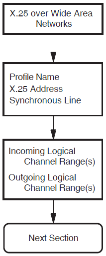
5.2. X.25 over Wide Area Network
This section allows you to enter details about an X.25 network to which your system is attached. You must provide information associated with the DTE connected to the named network. It is assumed that the system is to be attached to a public or private network and will have a DTE connected to the specified network.
Figure 5.2, ''X.25 over Wide Area Network Section'' illustrates the X.25 over Wide Area Network Section.
Profile Name
An X.25 profile is a set of parameters that indicate to X.25 for OpenVMS the correct operating procedures for a particular network. The profile name defines a specific profile. The valid profiles are given in the help text for this prompt. Typically, the profile name corresponds to the name of the PSDN.
X.25 Address
The X.25 address is the X.25 DTE address assigned by the PTT when the network connection to a Packet Switched Data Network (PSDN)is purchased. An X.25 address is a series of numeric digits similar to a telephone number.
Synchronous Line
The synchronous line indicates which of the available synchronous communications devices supported by this host can be used by the specified DTE for its connection to a PSDN. Select one of the available lines.
Incoming Logical Channel Range
{[start-of-range .. end-of-range]}{[1..4095]}. Separate multiple ranges using commas. For example, to
specify channels 1-3, 5-7, and 10-4095, enter {[1..3],[5..7],[10..4095]}.
Note that a range of one number must still be entered as a range. For example, to
specify only channel 4, enter {[4..4]}.Note
If you intend to define PVCs, ensure that you leave enough channel numbers
free to allow for the PVCs. For example, by entering the range
{[10..4095]}, 9 channels are left free for assignment to
PVCs.
Outgoing Logical Channel Range
The outgoing logical channel number range specifies what channel numbers can be used by X.25 for OpenVMS when an outgoing call request is made. This information is supplied by the PTT authority when the DTE subscription is made.
Enter the channel range in the same format as the incoming channel range. For example, to
enter the range 1 to 4095, enter {[1..4095]}.
See Note under Incoming Logical Channel Range.
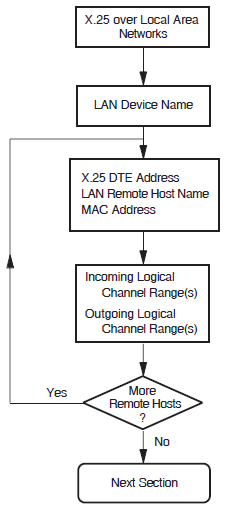
5.3. X.25 over Local Area Network
This section allows you to enter details about each of the LAN–based X.25 remote hosts you want to access from this system. For each LAN remote host you name, you must provide information on the DTE that is connected to the LAN.
Figure 5.3, ''X.25 over Local Area Network Section'' illustrates the X.25 over Local Area Network Section.
LAN Device Name
The LAN device name indicates which of the available LAN connections the LAN–based DTEs are to use as the connection to the LAN–based X.25 network. You are only permitted to specify one LAN device.
X.25 DTE Address
The X.25 DTE address is the X.25 address that is used by other nodes in this X.25 network to identify this DTE. A DTE address is a series of numeric digits similar to a telephone number. It must be unique within each X.25 network.
LAN Remote Host Name
The LAN remote host name is simply a name that is used to distinguish between the different
remote hosts. This name must be unique. For example, REMOTE-LAN-1.
To specify more than one LAN remote host, complete this section for the first remote host and then select to define another.
Remote MAC Address
The remote Media Access Control (MAC) address identifies the remote node accessed by this DTE.
This address is fixed. A MAC address consists of a series of up to twelve hexadecimal
digits, optionally separated by hyphens. For example:
1b-34-5f-78-e4-ab.
Note that each DTE may access only one other X.25 node on the LAN.
Incoming Logical Channel Range
{[start-of-range .. end-of-range]}{[1..4095]}. Separate multiple ranges using commas. For example, to
specify channels 1-3, 5-7, and 10-4095, enter {[1..3],[5..7],[10..4095]}.
Note that a range ofone number must still be entered as a range. For example, to specify
only channel 4, enter {[4..4]}.Note
If you intend to define PVCs, ensure that you leave enough channel numbers
free to allow for the PVCs. For example, by entering the range
{[10..4095]}, 9 channels are left free for assignment to
PVCs.
Outgoing Logical Channel Range
The outgoing logical channel number range specifies what channel numbers can be used by X.25 for OpenVMS when an outgoing callrequest is made.
Enter the channel range in the same format as the incoming logical channel range. For example,
to enter the range 1 to 4095, enter {[1..4095]}. See
Note under Incoming Logical Channel Range.
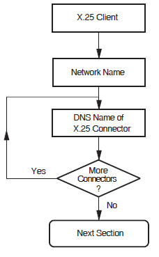
5.4. X.25 Client
This section allows you to enter details about an X.25 network to which your system is attached via one or more X.25 Connector systems through which your system gains access to the PSDN. You must provide the node names of the X.25 Connector systems that provide the connection to the required PSDN.
Figure 5.4, ''X.25 Client'' illustrates the X.25 Client Section.
Network Name
Note
The names that you choose for the network must correspond to the name of a local DTE class on the X.25 Connector system.
Connector Node Names
dnu:.zko.stardvbo:.afsg.comms.wernerdmiller:.sales.west_coast.salem.WillyLomandOZ:.QLD.Gold_Coast.Research_Park.Wasa
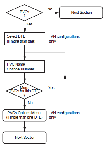
5.5. PVCs
This section is not presented if the X.25 Client Section is completed.
This section allows you to enter details about each of the Permanent Virtual Circuits (PVCs) to be used by your system. Your PSDN subscription will determine whether you are permitted to set up any PVCs.
Note
The information you enter in this section is used in the Incoming Call Security Section. If you modify this section after configuring security, VSI recommends that you also modify the Incoming Call Security Section.
PVC Name
The PVC name is simply a name that is used to distinguish between the different PVCs. This
name must be unique. For example, PVC-1.
Channel Number
The channel number must be specified as an integer and must lie outside the outgoing and incoming logical channel ranges specified in the X.25 over Wide Area Network Section or X.25 over Local Area Network Section.
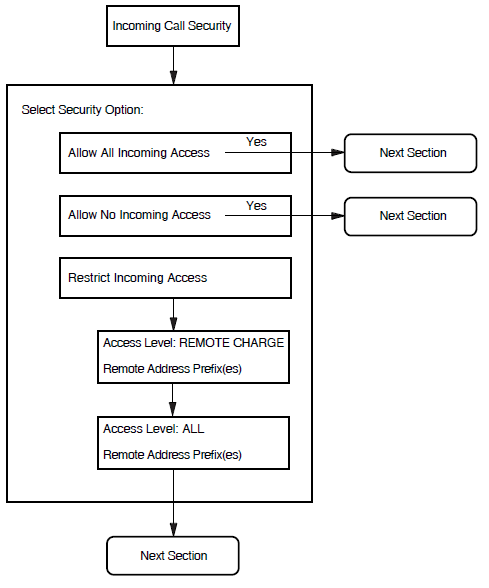
5.6. Incoming Call Security
This section allows you to enter details about the type of incoming call security to be applied to your X.25 system.
Figure 5.6, ''Incoming Call Security'' illustrates the Incoming Call Security Section.
Allow All Incoming Access
Allow No Incoming Access
Restrict Incoming Access
If the "Restrict Incoming Access" option is selected, you must define the access level to be granted to each remote DTE that needs to make an X.25 call to the local system.
|
Remote_Charge |
Remote DTEs are only permitted to make calls that do not contain a reverse charging request, that is, the local system will never be charged for the call |
|
All |
Remote DTEs are permitted to make any type of incoming calls to the local system |
Separate screens are presented for each access level. On the relevant screen, enter the Remote Address Prefix (RAP) of each remote DTE to be granted the specified access level.
Wildcards can also be used to specify an address. Entering only the wildcard, *, implies that the local system can receive calls from any DTE address.
Note that any calls from DTE addresses with RAPs that are not specified will be cleared.
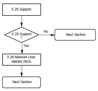
5.7. X.29 Support
Support for X.29 allows users to access the local system remotely via an X.25 network and to access remote systems via the X.25 network from the local system.
Figure 5.7, ''X.29 Support Section'' illustrates the X.29 Support Section.
X.29 Network User Identity
The X.29 Network User Identity (NUI) identifies the party that is to pay for each outgoing
call, and the DTE class to be used for the outgoing X.29 calls. Enter the NUI in the
form %x nnnnn or
'nnnnn'H where nnnnn can
consist of up to 107 octets.
5.8. X.25 Mail
X.25 Mail allows users to send mail to, and receive mail from, other systems that implement the Mail–11 protocol over X.25.
If you answer "Yes" when prompted whether to configure X.25 Mail, the configurator will create an account called X25$MAIL in which X.25 Mail will run when X.25 Mail calls are received by the system being configured.
TMPMBX privilege
PSI$X25_USER rights identifier
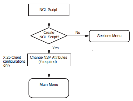
5.9. NCL Script
Figure 5.8, ''NCL Script'' illustrates the NCL Script Section.
When you reach this section, you have entered sufficient information to create a working X.25 configuration. If you want to verify some of the information you have entered, or add or delete some information, enter "Yes" in response to the question "Do you want to modify your answers?". The Sections Menu will be displayed, from which you can choose the section you want to review.
When you are sure that the information you have entered is correct and complete, display the Sections Menu and select the option "Create the NCL Script".
If the program creates the configuration file, a message is displayed which indicates the filename assigned to the file.
If, for some reason, the program cannot create the NCL script, error messages are displayed at the foot of the screen. If this occurs, you must correct the problem before making a further attempt to create the NCL script.
Next, if you have configured an X.25 Client system, you are presented with a screen that details the minimum number of session connections required for your X.25 for OpenVMS configuration. The number of connections is calculated on the basis of 128 connections per X.25 Connector node specified.
The configuration program now displays the number of Session Connections that can be established based on the configuration you have defined. You must ensure that the NSP attributes Maximum Transport Connections and Maximum Remote NSAPs are large enough to support this number of session connections. The default values of these attributes are 200 and 201 respectively.
Exit the configuration program.
Use NCL to disable the NSP entity.
Make the required NSP attribute changes.
Enable the NSP entity.
Chapter 6. Overview of ADVANCED Mode
6.1. Introduction to the ADVANCED Mode
The ADVANCED mode of the configuration program allows you to fully configure an VSI X.25 for OpenVMS system or to reconfigure an existing system.
To use the ADVANCED mode, you should have a good understanding of the X.25 management entities, the relationship between those entities, and a good understanding of X.25.
When you invoke the utility in ADVANCED mode, you can decide whether to create a new configuration or modify an existing configuration.
This mode of the configuration program can also be used to modify a configuration that was defined using the BASIC mode of the utility. When the utility is run, any existing configuration data is retrieved from the configuration database so that it can be viewed and, if required, modified.
6.2. Configuration Program Structure
The configuration program consists of a number of sections, each section corresponding to a logical group of information.
Details explaining the purpose of each section are given in Section 6.3, ''Configuration Sections'' and full details about the data required to complete each section are given in Chapter 7, "Required Configuration Data".
6.3. Configuration Sections
Note
Remote DTE Classes Section
Lines and DTEs Section
LLC2 DTEs Section
XOT DTEs Section
|
Configuration Section |
Applies to Direct Connect Systems? |
Applies to Client Systems? |
|---|---|---|
|
Remote DTE Classes |
No |
Yes |
|
Lines and DTEs? |
Yes |
No |
|
Yes |
No | |
|
Yes |
No | |
|
Session Connections |
No |
Yes |
|
PVCs |
Yes |
No |
|
Groups |
Yes |
No |
|
X.29 Support |
Yes |
Yes |
|
X.25 Mail |
Yes |
Yes |
|
Applications |
Yes |
Yes |
|
Relay Clients |
Yes |
No |
|
Filters |
Yes |
Yes |
|
Templates |
Yes |
Yes |
|
Reachable Addresses |
Yes |
Yes |
|
Server Clients and Filters |
Yes |
No |
|
Security |
Yes |
Yes |
|
Incoming Security: Applications |
Yes |
Yes |
|
Incoming Security: Filters |
Yes |
Yes |
|
Incoming Security: Relay Clients |
Yes |
No |
|
Outgoing Security: Local Processes |
Yes |
Yes |
|
NCL Script |
Yes |
Yes |
Remote DTE Classes
This section allows you to specify the DTE classes on the X.25 Connector systems that your X.25 Client system will use to access one or more PSDNs.
You must configure at least one Connector node to complete this section.
Lines and DTEs
This section allows you to enter details relevant to Lines and DTEs.
You must configure at least one synchronous line to complete this section. Choose a line on your system to configure for X.25 communications.
LLC2 DTEs
This section allows you to enter details relevant to LLC2 DTEs. This allows your system to communicate using X.25 over a local area network (LAN).
You must configure at least one LAN device to complete this section.
XOT DTEs
This section allows you to enter details relevant to XOT DTEs. This allows your system to communicate using X.25 over a TCP/IP connection.
You must configure at least one TCP/IP connection to complete this section.
Session Connections
This section allows you to specify the maximum number of session control connections (virtual circuits) supported by the X.25 for OpenVMS interface. This section is presented only if the Remote DTE Classes Section has been completed.
PVCs
This section allows you to define one or more Permanent Virtual Circuits (PVCs). Your PSDN subscription will determine whether you are permitted to set up any PVCs. This section is presented only if the Lines and DTEs Section, LLC2 DTEs Section, or XOT DTEs Section has been completed.
Groups
This section allows you to enter details of Closed User Groups (CUG) and Bilateral Closed User Groups (BCUG) on your system. Thissection is presented only if the Lines and DTEs Section, LLC2 DTEs Section, or XOT DTEs Section has been completed.
If your DTE belongs to a CUG, it can communicate freely with remote DTEs that are members of the same CUG. Your DTE's communication with other DTEs (outside the CUG) may be restricted, depending on your PSDN subscription options.
You must complete this section if you have requested this facility from your PSDN.
X.29 Support
This section allows you to add support for X.29 communications. X.29 support is required if you want users of character–mode terminals to be able to log in from this system to remote X.25 systems, or from remote X.25 systems to this system, using X.29 protocols.
X.25 Mail
This section allows you to add support for X.25 Mail. X.25 Mail is required if your X.25 for OpenVMS system is to send mail to,or receive mail from, other X.25 nodes.
Applications
This section allows you to specify X.25 and X.29 applications on your system that are used to accept incoming calls.
You must specify any X.25 or X.29 applications on your system, to allow incoming calls for those applications to succeed.
For each application you must define at least one filter, the name of the command file that starts the application, and a username.
Relay–Clients
This section allows you to specify X.25 Relay–Clients on your X.25 Relay system. This manual uses the term Relay–Clients to refer to the X.25 management entity on the X.25 Relay system that holds the information about the actual X.25 Relay Client system. These allow your system to relay incoming calls to other X.25 nodes in your local network.
For each X.25 Relay–Client, you must specify a DTE class and at least one filter. The filter is used to match incoming calls to the Relay–Client, and the DTE class and template (if present) are used by the Relay–Client when making the outgoing call used to relay the call.
Filters
This section allows you to specify the filters to be used to determine the action taken when an incoming call is received.
You must supply a filter name and a priority for each filter. You may leave all the other parameters unspecified.
The more parameters you specify in a filter, the more specific is that filter. For example,you could create a filter with most of its parameters unspecified, and with a low priority, to act as a "catchall" for unexpected calls.
One filter, called OSI Transport, is automatically created on your
system. In addition, if you choose X.29 support,an additional filter, called
X29, is created. If you choose X.25 Mail support, a third filter,
called X25_MAIL is also created.
Templates
This section allows you to define the templates to be used when an outgoing call is made.
Your system uses a template to make outgoing calls. The template sets various parameters for each call made using that template.
Two templates, called Default and OSI Transport, are
automatically created on your system. Appendix D, "Characteristic Values of the Default and OSI Transport Templates" lists the
characteristic values of these templates. In addition, if you choose X.29 support, two
additional templates, called X29Login and X29Server, are
created. If you want additional templates, then you must complete this section.
Reachable Addresses
This section allows you to define the addresses of remote DTEs that are permitted to communicate with the X.25 system.
If you have local applications that use NSAP addresses to communicate with remote DTEs, then you must complete this section to provide a mapping between NSAP addresses and DTE addresses. Reachable addresses are used to convert NSAP addresses into DTE addresses.
Server–Clients
This section allows you to specify X.25 Server–Clients on your system. This manual uses the term Server–Clients to refer to the X.25 management entity on the X.25 Connector system that holds the information about the actual X.25 Client system. These allow your Connector system to service requests from X.25 Client systems in your DECnet network.
For each X.25 Server–Client, you must specify at least one service node and at least one filter. The filter is used to match incoming calls to the Server–Client, and the service node is used by the server to identify the node to contact when making the connection to the X.25 Client system.
X.25 Security
- Create or modify X.25 security, which allows you to specify a detailed security setup in each of the following sections:
Incoming Security: Applications
You will see this section only if you have specified one or more applications to handle incoming calls. Complete this section if you want your applications to be able to receive calls from remote systems.
Incoming Security: Filters
You will see this section only if you have specified one or more filters to receive incoming calls. Complete this section for each filter you want to receive incoming calls.
Incoming Security: Relay–Clients
You will see this section only if you have specified one or more Relay–Clients to relay incoming calls. Complete this section for each Relay–Client you want to receive incoming calls.
Outgoing Security: Local Processes
You will see this section only if you have specified one or more applications. Complete this section if you want users on your system to be able to make calls to remote systems.
Allow outgoing X.25 calls only, which allows applications to make calls from this system, but does not allow any incoming calls to be accepted. No further security information is required if you choose this option.
Allow all X.25 calls, which allows all incoming and outgoing calls to be permitted by this system. It is strongly recommended that you do not choose this option if this system is connected to a public PSDN.
NCL Scripts
This section allows you to initiate the generation of NCL scripts based on the configuration data that you have entered.
This initiation should be performed only when you are satisfied that all the data you have entered is complete and correct.
Chapter 7. Required Configuration Data
7.1. Overview
This chapter details the information you will need to provide while running the configuration program in ADVANCED mode.
Tables 7.1 to 7.18 list all the information you will require during the configuration. You should write down the configuration parameter values specific to your system in Appendix A, "Values Specific to Your Configuration" (which provides a series of blank forms) and refer to that appendix when you run the configuration program. Note that the tables are presented in the order that the Sections are displayed if an X.25 system is configured for Client, WAN,and LAN usage.
|
Information required |
Form in which it is required |
Where to find information |
Default value or setting |
|---|---|---|---|
|
Remote DTE class name |
Max 32 characters |
You supply |
REMOTE-CLASS- n |
|
Outgoing session template? |
Max 32 characters |
You supply |
Default |
|
Segment size |
Decimal number |
You supply |
64 |
|
Node names |
Max 64 characters |
You supply |
– |
|
Information required |
Form in which it is required |
Where to find information |
Default value or setting |
|---|---|---|---|
|
Line name |
Select from list |
Available lines determined by program |
– |
|
Line speed |
Select from list |
Supplier of line |
4.8 |
|
Link name |
Max 32 characters |
You supply |
LINK- n |
|
DTE name |
Max 32 characters |
You supply |
DTE- n |
|
X.25 address |
Max 15 digits |
PSDN subscription information |
– |
|
Profile name |
PSDN/VSI |
– | |
|
DTE interface type |
DTE, DCE, or Negotiated |
You supply |
DTE |
|
Incoming logical channel ranges |
Numbers or ranges of numbers |
You supply? |
{[1...4095]} |
|
Outgoing logical channel ranges |
Numbers or ranges of numbers |
You supply ? |
{[1...4095]} |
|
Packet level negotiation? |
Yes or No |
– |
Yes |
|
Extended packet sequence numbering ? |
Yes or No |
– |
Yes |
|
Minimum packet size ? |
Decimal number |
You supply ? |
Profile dependent |
|
Maximum packet size? |
Decimal number |
You supply? |
Profile dependent |
|
Default packet size |
Decimal number |
You supply ? |
Profile dependent |
|
Level 3 minimum window size ? |
Decimal number |
You supply ? |
Profile dependent |
|
Level 3 maximum window size ? |
Decimal number |
You supply ? |
Profile dependent |
|
Level 3 default window size |
Decimal number |
You supply ? |
Profile dependent |
|
Extended frame sequence numbering ? |
Yes or No |
– |
Yes |
|
Level 2 window size |
Decimal number |
You supply ? |
Profile dependent |
|
Level 2 maximum data size |
Decimal number |
You supply ? |
Profile dependent |
|
Frame size |
Decimal number |
You supply ? |
Profile dependent |
|
Link interface type |
DTE or DCE |
You supply ? |
DTE |
|
Segment size |
Decimal number |
PSDN Subscription information |
Profile dependent |
|
Inbound DTE class |
Max 32 characters |
You supply |
Profile name |
|
Information required |
Form in which it is required |
Where to find information |
Default value or setting |
|---|---|---|---|
|
LAN device name |
– |
Available devices determined by program |
– |
|
LLC2 DTE name |
Max 32 characters |
You supply |
DTE- n |
|
LLC2 DTE address |
Max 15 digits |
You supply |
– |
|
Local LSAP address |
2 Hex digits |
You supply |
7E |
|
Level 3 profile |
Max 32 characters |
You supply |
ISO8881 |
|
Incoming logical channel ranges |
Numbers or ranges of numbers |
You supply, in consultation with remote system |
{[1..4095]} |
|
Outgoing logical channel ranges |
Numbers or ranges of numbers |
You supply, in consultation with remote system |
{[1..4095]} |
|
Remote MAC address |
LAN hardware address |
Remote system |
– |
|
Remote LSAP address |
2 Hex digits |
You supply |
7E |
|
Link Interface type |
DTE, DCE, or Negotiated |
You supply |
Negotiated |
|
Packet level negotiation |
Yes or No |
– |
No |
|
Extended packet sequence numbering |
Yes or No |
– |
No |
|
Minimum packet size ? |
Decimal number |
You supply |
16 |
|
Maximum packet size ? |
Decimal number |
You supply |
1024 |
|
Default packet size |
Decimal number |
You supply |
128 |
|
Level 3 minimum window size ? |
Decimal number |
You supply |
1 |
|
Level 3 maximum window size ? |
Decimal number |
You supply |
7 |
|
Level 3 default window size |
Decimal number |
You supply |
2 |
|
Inbound DTE class |
Max 32 characters |
You supply |
LLC2-CLASS- n |
|
Information required |
Form in which it is required |
Whereto find information |
Default value or setting |
|---|---|---|---|
|
Local TCP/IP address |
TCP/IP address |
You supply |
0.0.0.0 |
|
XOT DTE name |
Max 32 characters |
You supply |
DTE- n |
|
XOT DTE address |
Max 15 digits |
You supply |
– |
|
Local RFC1613 port number |
4 digits |
You supply |
1998 |
|
Level 3 profile |
Max 32 characters |
Fixed value |
ISO8881 |
|
Incoming logical channel ranges |
Numbers or ranges of numbers |
You supply, in consultation with remote system |
{[1..4095]} |
|
Outgoing logical channel ranges |
Numbers or ranges of numbers |
You supply, in consultation with remote system |
{[1..4095]} |
|
Remote TCP/IP address |
TCP/IP address |
Remote system |
– |
|
Remote RFC1613 port number |
4 digits |
You supply |
1998 |
|
Packet level negotiation |
Yes or No |
– |
No |
|
Minimum packet size ? |
Decimal number |
You supply |
16 |
|
Maximum packet size ? |
Decimal number |
You supply |
1024 |
|
Default packet size |
Decimal number |
You supply |
128 |
|
Level 3 minimum window size ? |
Decimal number |
You supply |
1 |
|
Level 3 maximum window size ? |
Decimal number |
You supply |
7 |
|
Level 3 default window size |
Decimal number |
You supply |
2 |
|
Inbound DTE class |
Max 32 characters |
You supply |
XOT-CLASS- n |
|
Information required |
Form in which it is required |
Where to find information |
Default value or setting |
|---|---|---|---|
|
DTE name |
Max 32 characters |
Select from list |
DTE- n |
|
PVC name |
Max 32 characters |
You supply |
PVC- n |
|
Channel number |
Integer ? |
PSDN subscription information |
- |
|
Packet size |
Decimal number |
You supply? |
Profile dependent |
|
Window size |
Decimal number |
You supply ? |
Profile dependent |
|
Information required |
Form in which it is required |
Where to find information |
Default value or setting |
|---|---|---|---|
|
Group name |
Max 32 characters |
You supply |
GROUP- n |
|
Group type |
BCUG, CUG, or CUGOA |
You supply? |
CUG |
|
DTE name |
– |
Select from list |
– |
|
CUG number |
Decimal number |
PSDN subscription information |
– |
|
Remote DTE address ? |
Max 15 digits |
PSDN subscription information |
– |
|
Information required |
Form in which it is required |
Where to find information |
Default value or setting |
|---|---|---|---|
|
Name |
Max 20 characters |
You supply |
APPLICATION_ n |
|
Type |
X.25 or X.29 |
You supply |
X.25 |
|
Command file [to start application] |
OpenVMS full filename Max 128 characters |
You supply |
– |
|
Username [for application] |
OpenVMS username Max 12 characters |
You supply |
– |
|
Template ? |
Max 32 characters |
You supply |
Default |
|
Filter names ? |
Max 20 chars |
You supply |
FILTER_n |
|
Information required |
Form in which it is required |
Where to find information |
Default value or setting |
|---|---|---|---|
|
Client name |
Max 32 characters |
You supply |
RELAY--n |
|
DTE class |
Max 32 characters |
You supply |
– |
|
Template |
Max 32 characters |
You supply |
Default |
|
Filter names ? |
Max 32 characters |
You supply |
FILTER_n |
|
Information required |
Form in which it is required |
Where to find information |
Default value or setting |
|---|---|---|---|
|
Name |
Max 20 characters |
You supply |
FILTER_ n |
|
Priority |
Decimal number |
You supply |
1 |
|
Incoming DTE address |
Max 15 digits |
You supply |
– |
|
Call data mask |
Hex digits |
You supply |
– |
|
Call data value |
Hex digits |
You supply |
– |
|
DTE class |
Max 32 characters |
You supply |
– |
|
Sending DTE address |
Max 15 digits |
You supply |
– |
|
Receiving DTE address |
Max 15 digits |
You supply |
– |
|
Group name |
Max 32 characters |
You supply |
– |
|
Originally called address |
Max 15 digits |
You supply |
– |
|
Redirect reason |
One of: 0 Unspecified 1 Busy 2 Out of order 3 Systematic |
You supply |
– |
|
Called address extension mask |
Hex digits |
You supply |
– |
|
Called address extension value |
Hex digits |
You supply |
– |
|
Called NSAP |
Decimal number |
You supply |
– |
|
Information required |
Form in which it is required |
Where to find information |
Default value or setting |
|---|---|---|---|
|
Template name |
Max 32 characters |
You supply |
TEMPLATE- n |
|
DTE class |
Max 32 characters |
You supply |
– |
|
Call data |
Hex digits |
You supply |
– |
|
Packet size |
Decimal Number |
You supply |
– |
|
Window size |
Decimal number |
You supply |
– |
|
Destination DTE address |
Max 15 digits |
You supply |
– |
|
Fast select option |
One of: 0 Unspecified 1 Fast select 2 With response 3 No fast select |
You supply |
0 |
|
Reverse charging |
Allow or Do not allow |
You supply |
Do not allow |
|
Selected group |
Max 32 characters |
You supply |
– |
|
Throughput class request |
A range of values, the max and min to be chosen from: 0, 75, 150, 300, 600, 1200, 2400, 4800, 9600, 19200, 48000 |
You supply |
{0..0} |
|
Network user identity |
Octet string |
You supply |
– |
|
Local facilities |
Hex digits |
You supply |
– |
|
Charging information |
Display or Do not display |
You supply |
Do not display |
|
RPOA sequence |
Sequence of octet strings of 4 decimal digits |
You supply |
– |
|
Local subaddress |
Decimal number |
You supply |
– |
|
Target address extension |
NSAP Address |
You supply |
– |
|
NSAP mapping |
Yes or No |
You supply |
No |
|
Calling address extension |
NSAP Address |
You supply |
– |
|
Transit delay selection |
Decimal number |
You supply |
0 |
|
End-to-End delay |
Range of decimal numbers |
You supply |
{0..0} |
|
Expedited data option |
One of: Use Do not use Not specified |
You supply |
Not specified |
|
Information required |
Form in which it is required |
Where to find information |
Default value or setting |
|---|---|---|---|
|
Reachable address name |
Max 32 characters |
You supply |
– |
|
Address prefix |
Complete or partial NSAP address, including at least the AFI |
You supply |
– |
|
DTE class for outgoing calls |
Max 32 characters |
You supply |
– |
|
Use DTE address extensions |
Yes or No |
You supply |
Yes |
|
Conversion mechanism |
X.121 or Manual |
You supply |
X.121 |
|
Destination DTE address? |
Max 15 digits |
You supply |
– |
|
Information required |
Form in which it is required |
Where to find information |
Default value or setting |
|---|---|---|---|
|
Client name |
Max 32 characters |
You supply |
CLIENT-- n |
|
Service nodes |
Max 32 characters |
You supply |
– |
|
Filter names ? |
Max 32 characters |
You supply |
FILTER_n |
|
Rights identifiers |
Max 32 characters |
You supply |
– |
|
Information required |
Form in which it is required |
Where to find information |
Default value or setting |
|---|---|---|---|
|
Select an application |
– |
List supplied by program |
– |
|
DTE addresses of systems that can call this application only if they pay for the call |
Max 15 digits. Can be a full DTE address or a Remote Address Prefix (RAP) ? |
You supply |
– |
|
DTE addresses of systems that can call this application irrespective of who pays for the call |
Max 15 digits. Can be a full DTE address or a Remote Address Prefix (RAP) |
You supply |
– |
|
DTE addresses of systems that cannot call this application |
Max 15 digits. Can be a full DTE address or a Remote Address Prefix (RAP) |
You supply |
*? |
|
Information required |
Form in which it is required |
Where to find information |
Default value or setting |
|---|---|---|---|
|
Select a filter |
– |
You supply |
– |
|
DTE addresses of systems that can call processes using this filter only if they pay for the call |
Max 15 digits. Can be a full DTE address or a Remote Address Prefix (RAP) ? |
You supply |
– |
|
DTE addresses of systems that can call processes using this filter irrespective of who pays for the call |
Max 15 digits. Can be a full DTE address or a Remote Address Prefix (RAP) |
You supply |
– |
|
DTE addresses of systems that cannot call processes using this filter |
Max 15 digits. Can be a full DTE address or a Remote Address Prefix (RAP) |
You supply |
* ? |
|
Information required |
Form in which it is required |
Where to find information |
Default value or setting |
|---|---|---|---|
|
Select a Relay–Client |
– |
You supply |
– |
|
DTE addresses of systems that can call processes using this X.25 Relay–Client only if they pay for the call |
Max 15digits. Can be a full DTE address or a Remote Address Prefix(RAP) ? |
You supply |
– |
|
DTE addresses of systems that can call processes using this X.25 Relay–Client irrespective of who pays for the call |
Max 15 digits. Can be a full DTE address or a Remote Address Prefix(RAP) |
You supply |
– |
|
DTE addresses of systems that cannot call processes using this X.25 Relay–Client |
Max 15 digits. Can be a full DTE address or a Remote Address Prefix (RAP) |
You supply |
* ? |
|
Information required |
Form in which it is required |
Where to find information |
Default value or setting |
|---|---|---|---|
|
Rights Identifier ? |
– |
You supply |
– |
|
DTE addresses of systems that can be called by processes with this rights identifier only if they pay for the call |
Max 15 digits. Can be a full DTE address or a Remote Address Prefix (RAP)? |
You supply |
– |
|
DTE addresses of systems that can be called by processes with this rights identifier irrespective of who pays for the call |
Max 15 digits. Can be a full DTE address or a Remote Address Prefix (RAP) |
You supply |
– |
|
Names of PVCs that can be used by processes with this rights identifier ? |
Name of existing PVC |
You supply |
- |
|
DTE addresses of systems that cannot be called by processes with this rights identifier |
Max 15 digits. Can be a full DTE address or a Remote Address Prefix (RAP) |
You supply |
*? |
|
Names of PVCs that cannot be used by processes with this rights identifier ? |
Name of existing PVC |
You supply |
– |
Chapter 8. Flowcharts and Associated Notes
This chapter contains flowcharts illustrating each section in the ADVANCED mode of the configuration program, together with notes about each section.
8.1. Introduction
Figure 8.1, ''Introduction'' illustrates the Introduction Section.
The Introduction Section provides you with options to create a new X.25 for OpenVMS configuration, modify an existing configuration, or exit from the program. These options are detailed more fully in subsections 8.1.1, 8.1.2, and 8.1.3 respectively.
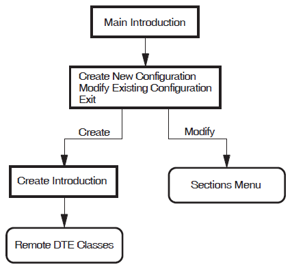
8.1.1. Creating a New Configuration
Select the "Create a new configuration script" option. (You don't need to perform this step if this is a new installation.)
The configuration program displays the CREATE Introduction Section. This section displays the main connection sections and the type of X.25 system you will create if you select that section. The choices are:- Remote DTE Classes (for X.25 Client through an X.25 Connector system)
- Lines and DTEs (for X.25 over a wide area network)
- LLC2 (for X.25 over a local area network)
- XOT (for X.25 over TCP/IP)
The configuration program then displays each section in the same order as the list. To create a usable configuration, you must complete at least one of the specified sections.
You do not have to complete every section, only those that present functions that you want to configure. For example, if you do not want to configure your system as a Client, you do not have to complete the Remote DTE Classes Section. When the current section has been completed, an Options Menu relevant to that section is displayed. The Options Menu gives you the opportunity to amend the current section or to move on to another section.
Complete the current section or select to move on to the next section.
Repeat step 2 for each of the sections. To create a configuration script you must complete the NCL Script Section.
8.1.2. Modifying an Existing Configuration
Select the "Modify an existing configuration script" option.
The Sections Menu is displayed, which presents the sections that can be modified. These are:Remote DTE Classes
Lines and DTEs
LLC2 DTEs
XOT DTEs
Session Connections
PVCs
Groups X.29 Support
X.25 Mail
Applications
X.25 Relay–Clients
Filters
Templates
Reachable Addresses
Server–Clients
- Security
Incoming Security: Applications
Incoming Security: Filters
Incoming Security: X.25 Relay–Clients
Outgoing Security: Local Processes
NCL Script
Note that the full list of sections is determined by which configuration sections have been created. The above list indicates the sections displayed if all sections have been created. Initially, one of the sections is highlighted to indicate that it is the current section.
To configure a section, use the up–arrow and down–arrow keys to highlight the required section (and hence make it current) and then press Return.
The Options Menu for the specified section is displayed and allows you to modify the existing data.
For further details on modifying an existing configuration and facts that you should be aware of before making any modifications,refer to Chapter 10, "Modifying the Configuration".
8.1.3. Exiting the Configuration Program
To leave the configuration program, select the option "Exit this program" from the Main Menu.
Full details of quitting and leaving the configuration program are provided in Chapter 2, "Using the Configuration Program".
8.2. Remote DTE Classes
Figure 8.2, ''Remote DTE Classes'' illustrates the Remote DTE Classes Section.
This section allows you to define remote DTE classes, in which you specify the X.25 Connector systems that your Client system will use in making a call.
Remote DTE Class Name
The name you specify for a remote DTE class on an X.25 Client system must match the name of a local DTE class on the X.25 Connector system you specify in the Connector Node Names list.
Outgoing Session Template
Specify the name of an OSI TRANSPORT TEMPLATE entity on the X.25 Client system that the Client should use when establishing the DECnet–Plus connection to the X.25 Connector system. If the template doesn't exist, you must create the template using the DECnet–Plus configuration program.
Connector Node Names
You must specify the name of at least one X.25 Connector node hosting the local DTE class referenced by this remote DTE class.
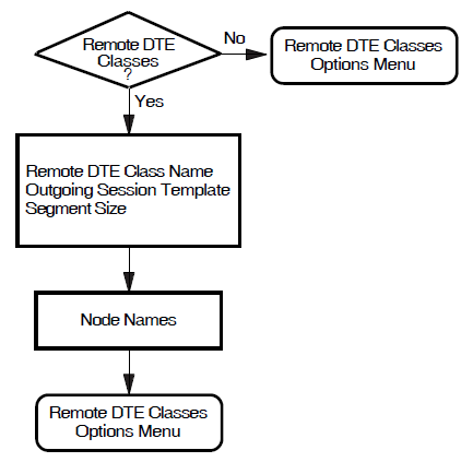
8.3. Lines and DTEs
Figure 8.3, ''Lines and DTEs'' illustrates the Lines and DTEs Section.
This section allows you to configure synchronous lines and associated DTEs. You must set up at least onesynchronous line and associated DTE, unless you intend to set up LLC2 or XOT DTEs on your system.
Synchronous Line
This screen displays the available synchronous lines. Only lines configured when the synchronous devices were installed are presented. Select a line for the specified DTE. You will have the opportunity to set up further lines later.
Line Speed
The available line speeds are displayed. Select a speed for the line.
Link Name, DTE Name, X.25 Address, and Inbound DTE Class
You will be required to provide a unique link name, DTE name, and X.25 DTE address to identify the DTE to be associated with the line you select.
Additionally, before completing this section the configuration program will prompt you to enter the Inbound DTE Class with which the DTE is associated. All calls received on the DTE will be associated with the indicated DTE class.
Profile Name
You must provide the name of the profile to be used by the DTE you specified. Information on frame and packet control parameters will be derived from the profile you specify.
If you want to set up a point–to–point link then the ISO8208 profile should be specified.
Logical Channel Ranges
Logical channel numbers are required to identify logical links between your system and the PSDN for both incoming and outgoing calls. See Section 5.2, ''X.25 over Wide Area Network'' for more detailed information about the required syntax.
If you intend to configure any PVCs, select Logical Channel Ranges for the SVCs that leave enough channels free for the required PVCs.
Extended Packet Sequence Numbering
If the profile you have selected supports extended packet sequence numbering, you will be prompted whether you want to use this facility.
Packet Level Negotiation
If the profile you have selected supports packet level negotiation, you will be prompted whether to use this facility. If you select to use the facility, you will be prompted to specify the minimum, maximum, and default packet size to be used, and to specify the level 3 minimum, maximum, and default window size. If you select not to use the facility, you will be prompted to enter the packet size and level 3 window size to be used.
Extended Frame Sequence Numbering
If the profile you have selected supports extended frame sequence numbering, you will be prompted whether you want to use this facility.
Link Interface Type
If the DTE is connected to a PSDN, you should select DTE for the interface type.
If the DTE is to use a point–to–point protocol (that is, ISO8208), you must set the interface type correctly for both DTEs. Two DTEs using a point–to–point protocol can communicate only if one is set to DCE, and the other is set to DTE.
Segment Size
The call will be charged based on the number of segments sent. Thus, this value must be provided if you want to generate accounting records. Note that the value must match the value set in the network.
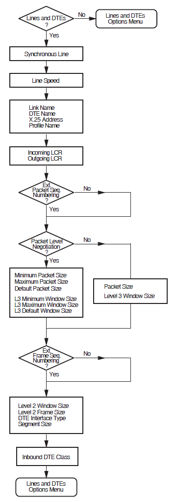
8.4. LLC2 DTEs
Figure 8.4, ''LLC2 DTEs'' illustrates the LLC2 DTEs Section.
This section allows you to configure LLC2 DTEs.
LAN Device Name
The LAN devices available on your system are displayed. Choose one to associate with your LLC2 SAP DTE. You will have the opportunity to set up further LLC2 DTEs later, using either a different LAN device (if you have more than one) or the same one.
LLC2 DTE Name, LLC2 DTE Address, Local LSAP Address, and Inbound DTE Class
You must provide a unique name and address to identify the LLC2 DTE to be associated with the link you select. In addition, you must specify the Link Service Access Point (LSAP) for the specified LLC2 DTE.
Additionally, before completing this section the configuration program will prompt you to enter the Inbound DTE Class with which the DTE is associated. All calls received on the DTE will be associated with the indicated DTE class.
Level 3 Profile
You must provide the name of the profile to be used by the LLC2 DTE you specified. For most LANs, the profile used is ISO8881. Information on frame and packet control parameters will be derived from the profile you specify.
Logical Channel Ranges
Logical channel numbers are required to identify logical links between the LLC2 DTEs for both incoming and outgoing calls. See Section 5.2, ''X.25 over Wide Area Network'' for more detailed information about the required syntax.
If you intend to configure any PVCs, select Logical Channel Ranges for the SVCs that leave enough channels free for the required PVCs.
Remote System Parameters
You must provide the unique Media Access Control (MAC) address of the remote system and the Link Service Access Point (LSAP) for the remote LLC2 DTE.
Link Interface Type
For two systems to communicate using the LLC2 protocol, one must be configured as a DCE and one as a DTE. You must determine the interface type being used by the remote system and the select the appropriate type for the local system. If the interface typebeing used by the remote system is unknown, set the interface type to Negotiated.
Extended Packet Sequence Numbering
If the profile you have selected supports extended packet sequence numbering, you will be prompted whether you want to use this facility.
Packet Level Negotiation
If the profile you have selected supports packet level negotiation, you will be prompted whether to use this facility. If you select to use the facility, you will be prompted to specify the minimum, maximum, and default packet size to be used, and to specify the level 3 minimum, maximum, and default window size. If you select not to use the facility, you will be prompted to enter the packet size and level 3 window size to be used.
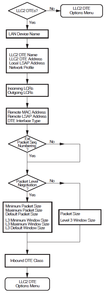
8.5. XOT DTEs
Figure 8.5, ''XOT DTEs'' illustrates the XOT DTEs Section.
This section allows you to configure XOT DTEs.
Local TCP/IP Address
Note
By default, XOT's single SAP entity is configured to listen on any available IP interface (as specified by the local IP address 0.0.0.0). You can create multiple SAP entities, each listening on a unique IP address. However, if you create more than one SAP entity, you must assign each entity a unique IP address; no SAP entity can use the 0.0.0.0 address.
XOT DTE Name, XOT DTE Address, Local RFC1613 Port Number, and Inbound DTE Class
You must provide a unique name and address to identify the XOT DTE to be associated with the link you select. In addition, you must specify the local RFC1613 port number for the specified XOT DTE SAP. VSI recommends that you use the value 1998 as specified in RFC 1613.
Additionally, before completing this section the configuration program will prompt you to enter the Inbound DTE Class with which the DTE is associated. All calls received on the DTE will be associated with the indicated DTE class.
Level 3 Profile
You must provide the name of the profile to be used by the XOT DTE you specified. You must specify ISO8881. Information on frame and packet control parameters will be derived from the profile you specify.
Logical Channel Ranges
Logical channel numbers are required to identify logical links between the XOT DTEs for both incoming and outgoing calls. See Section 5.2, ''X.25 over Wide Area Network'' for more detailed information about the required syntax.
If you intend to configure any PVCs, select Logical Channel Ranges for the SVCs that leave enough channels free for the required PVCs.
Remote System Parameters
You must provide the unique IP address of the remote system and the RFC 1613 TCP port number of the remote system for the XOT DTE SAP link.
Packet Level Negotiation
If the profile you have selected supports packet level negotiation, you will be prompted whether to use this facility. If you select to use the facility, you will be prompted to specify the minimum, maximum, and default packet size to be used, and to specify the level 3 minimum, maximum, and default window size. If you select not to use the facility, you will be prompted to enter the packet size and level 3 window size to be used.
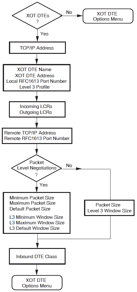
8.6. Session Connections
This section is available only if the Remote DTE Classes Section has been completed.
This section allows you to specify the maximum number of session control connections (virtual
circuits) supported by the X.25 for OpenVMS interface. A value must be entered for this parameter. The default value is
10.
SYS$SYSTEM:MODPARAMS.DAT: ADD_CHANNELCNT
ADD_NPAGEDYN
ADD_NPAGEVIRNote
@SYS$UPDATE:AUTOGEN SAVPARAMS REBOOT FEEDBACK
8.7. PVCs
This section is available only if the Lines and DTEs Section, LLC2 DTEs Section, or XOT DTEs Section has been completed.
Figure 8.6, ''PVCs'' illustrates the PVCs Section.
This section allows you to set up permanent virtual circuits between the host system and specified DTEs.
DTE Name
Each of the DTEs created in the Lines and DTEs Section, LLC2 DTEs Section, and XOT DTEs Section are listed. Select one from the list.
PVC Name
Enter the name of the PVC.
For each PVC you name, you must define values for the channel number, packet size, and window size.
Channel Number
The channel number entered must not be within the range of incoming and outgoing logical channel numbers specified in the Lines and DTEs Section, LLC2 DTEs Section, or XOT DTEs Section. The logical channel number range currently defined for PVCs is displayed beneath the DTE name at the top of the screen.
The channel number should be unique amongst PVCs associated with the specified DTE.
Packet Size and Window Size
The default values for the packet size and window size are taken from the profile specified in the Line and DTEs Section, LLC2 DTEs Section, or XOT DTEs Section. The default values can be overridden if required.
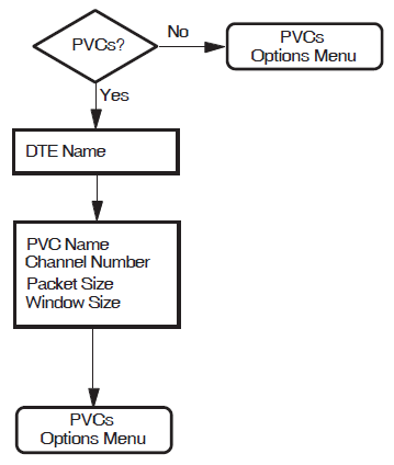
XOT PVCs
For PVC circuits to interoperate correctly over a XOT DTE, it is necessary to specify additional information in the NCL configuration for the PVC. EachXOT PVC must have a REMOTE PVC NAME specified via NCL, via the command:
SET X25 PROTOCOL DTE dte-name PVC pvc-name REMOTE PVC N
The name should match the name configured on the remote system. The X.25 Configurator does not support this attribute when creating a PVC, so the appropriate NCL command should be placed in the file SYS$STARTUP:X25$EXTRA_SET.NCL.
8.8. Groups
This section is available only if the Lines and DTEs Section, LLC2 DTEs Section, or XOT DTEs Section has been completed.
Figure 8.7, ''Groups'' illustrates the Groups Section.
This section allows you to assign any of the DTEs you have created to Closed User Groups (CUGs), Bilateral Closed User Groups(BCUGs), or Closed User Groups with Outgoing Access (CUGOAs).
All the DTEs you have created are listed.
To place a DTE in a group, enter the PSDN–assigned CUG, BCUG, or CUGOA number beside that DTE. The same number can be assigned to more than one DTE.
To remove a DTE from a CUG or BCUG, delete the CUG or BCUG number associated with that DTE.
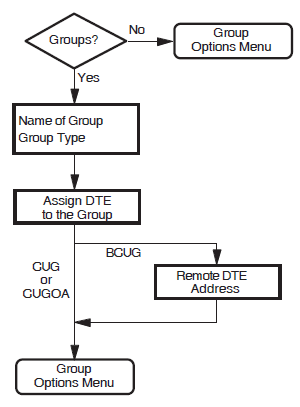
8.9. X.29 Support
Figure 8.8, ''X.29 Support'' illustrates the X.29 Support Section.
This section allows you to provide support for X.29 communications.
You are prompted to provide the network user identity (NUI) to identify the party that is to pay for each outgoing call, and the DTE class to be used for the outgoing X.29 calls.
Note that if you answer "No" to configuring X.29 Support, no further questions will be displayed. Instead, the X.29 Support Options Menu is displayed from which you can move on to the next section.
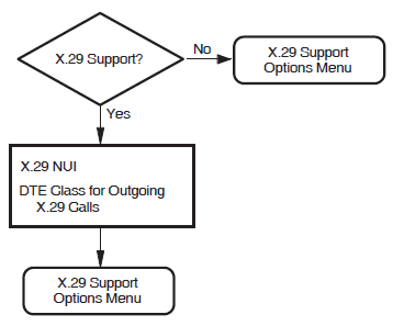
8.10. X.25 Mail
This section allows you to provide support for X.25 Mail.
X.25 for OpenVMS uses an OpenVMS account (X25$MAIL) in which X.25 Mail runs when an incoming X.25 Mail call is received by your system. If the required account does not exist, it will be created before you exit the configuration program.
TMPMBX privilege
PSI$X25_USER rights identifier
Note that if you answer "No" to configuring X.25 Mail, no account is created. Instead, the X.25 Mail Options Menu is displayed from which you can move on to the next Section.
8.11. Applications
Figure 8.9, ''Applications'' illustrates the Applications Section.
This section allows you to specify any applications running on your system.
Application Name, Application Type, Command File, and Username
The name you give an application is used to generate a rights identifier in the file
SYS$STARTUP:X25$SECURITY_IDENTIFIERS.COM. For example, if you enter the
application name TEST$1, and subsequently specify (in the Incoming Security:
Applications Section) that one or more remote DTEs should be given an access level of
REMOTE CHARGE, the rights identifier created will be APPL_TEST$1_REMOTE. Similarly, if
you specify that one or more remote DTEs should be given an access level of ALL, the
rights identifier created will be APPL_TEST$1_ALL.
They must only consist of alphanumeric characters, "$", and "_".
They must contain at least one non–numeric character.
They cannot be more than 20 characters in length.
Finally, you must provide the name of the command file that starts the application and a user name.
Application Templates
Default template will be used.Note
You cannot specify a template for an X.25 application. The Application
Template prompt is not displayed if you specify the application type as
X.25.
Application Filters
You must create at least one unique filter for each application. The Filter Name and Priority fields are mandatory; the other fields are optional. Note that you can set attributes to "unspecified" by leaving the appropriate field blank.
If you want to add a further filter to this application, answer "Yes" to the prompt "Do you want to associate another filter with the same application?".
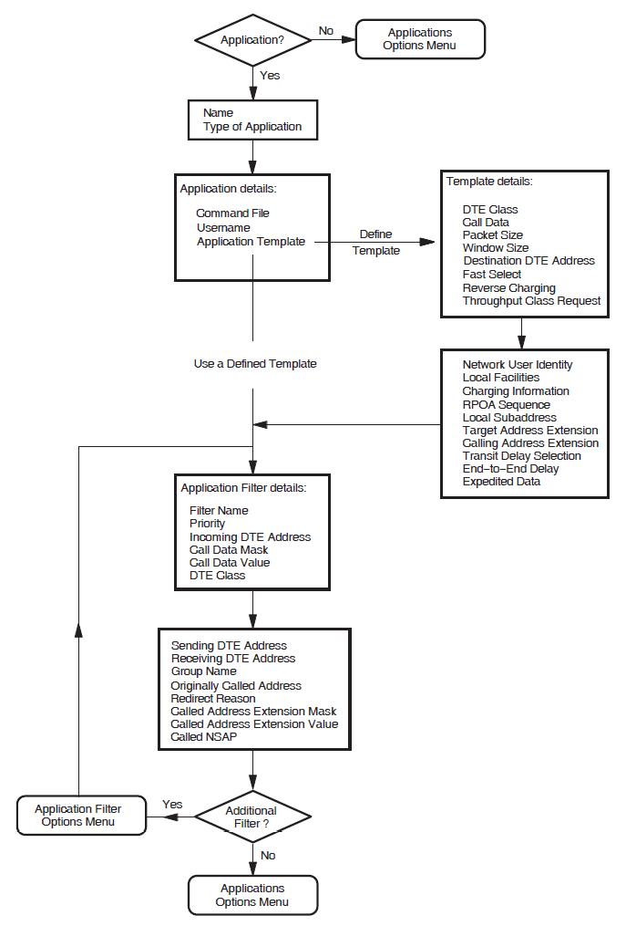
8.12. X.25 Relay–Clients Section
Figure 8.10, ''X.25 Relay–Clients'' illustrates the X.25 Relay–Clients Section.
The X.25 Relay–Clients Section allows you to set up call relaying from one DTE to another.
Client Name
You must specify a unique name for each Relay–Client. The name you give a
Relay–Client is used to generate a rights identifier in the file
SYS$STARTUP:X25$SECURITY_IDENTIFIERS.COM. For example, if you enter the
Relay–Client name TEST$1, and subsequently specify (in the Incoming Security:
Relay–Clients Section) that one or more remote DTEs should be given an access
level of REMOTE CHARGE, the rights identifier created will be RELAY_TEST$1_REMOTE.
Similarly, if you specify that one or more remote DTEs should be given an access level
of ALL, the rights identifier created will be RELAY_TEST$1_ALL.
They must only consist of alphanumeric characters, "$", and "_". The configuration program relaxes this restriction by converting any hyphens to underscores when creating the rights identifier.
They must contain at least one non–numeric character.
They cannot be more than 20 characters in length.
DTE Class
You must specify the DTE class that the Relay–Client should use to make the outgoing call as part of the relay function.
In order for a call to be forwarded on a Relay connection, the DTE that received the inbound call must be configured to be in DCE mode.
Template
You must specify one template for each X.25 Relay–Client. If you specify a template
other than the Default template,the specified template will be created and
its attributes amended if required. The Relay–Client uses the template when making
the outgoing call as part of the relay function.
X.25 Relay–Clients may share templates, that is, you can specify the same template for more than one X.25 Relay–Client.
Filters
You must specify at least one unique filter for each X.25 Relay–Client. The Filter Name and Priority fields are mandatory; all other fields are optional. Incoming calls are handled by an X.25 Relay–Client only if they match one of that client's filters.
When creating an X.25 Relay–Client you can create a number of filters. To add, modify, or delete filters associated with an existing X.25 Relay–Client, select the "Modify" option on the X.25 Relay–Client Options Menu.
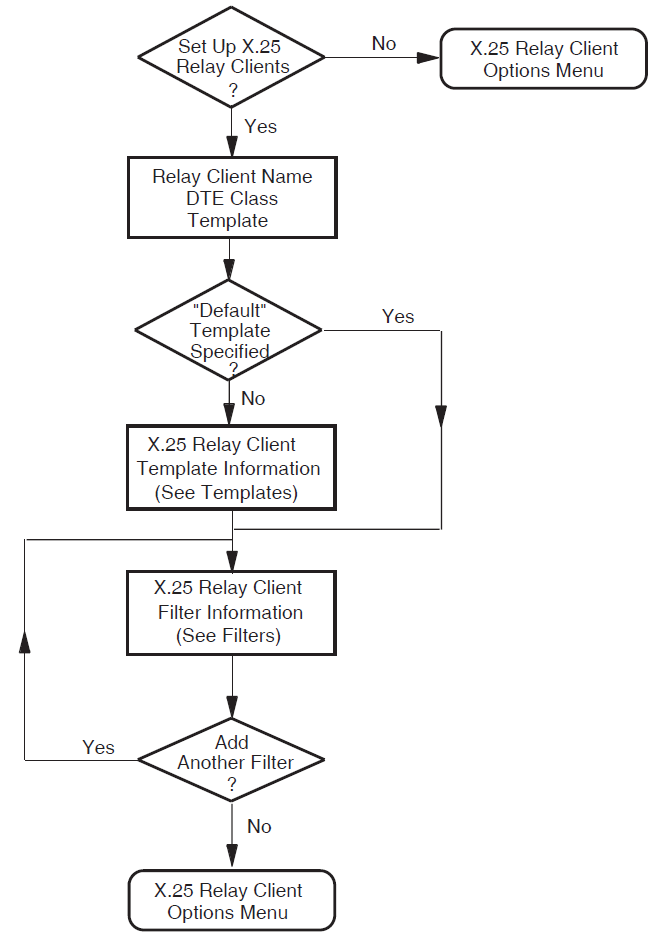
8.13. Filters
Figure 8.11, ''Filters'' illustrates the Filters Section.
This section allows you to create additional filters to screen incoming calls. The Filter Name and Priority fields are mandatory.
Note that you can set attributes to "unspecified" by leaving the appropriate field blank.
Filter Names
The name you give a filter is used to generate a rights identifier in the file
SYS$STARTUP:X25$SECURITY_IDENTIFIERS.COM. For example, if you enter the
filter name TEST$1, and subsequently specify (in the Incoming Security: Filters Section)
that one or more remote DTEs should be given an access level of REMOTE CHARGE, the
rights identifier created will be FILTER_TEST$1_REMOTE. Similarly, if you specify that
one or more remote DTEs should be given an access level of ALL, the rights identifier
created will be FILTER_TEST$1_ALL.
They must only consist of alphanumeric characters, "$", and "_".
They must contain at least one non–numeric character.
They cannot be more than 20 characters in length.
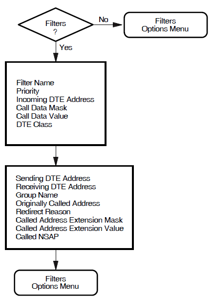
8.14. Templates
Figure 8.12, ''Templates'' illustrates the Templates Section.
The Default and OSI Transport templates are set up automatically.
The characteristic values of these templates are given in Appendix D, "Characteristic Values of the Default and OSI Transport Templates".
This section allows you to create additional templates with which to make outgoing calls.
Note that you can set attributes to "unspecified" by leaving the appropriate field blank.
The Template Name field is the only mandatory field.
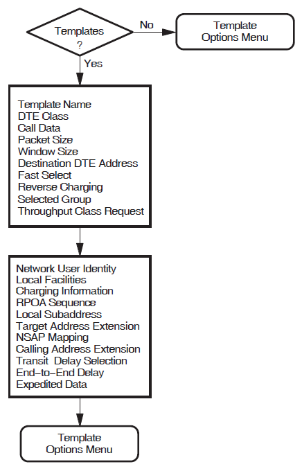
8.15. Reachable Addresses
Figure 8.13, ''Reachable Addresses'' illustrates the Reachable Addresses Section.
This section allows you to convert NSAP addresses to DTE addresses.
Choose either "X.121" or "Manual" for the mechanism by which the destination DTE address is supplied.
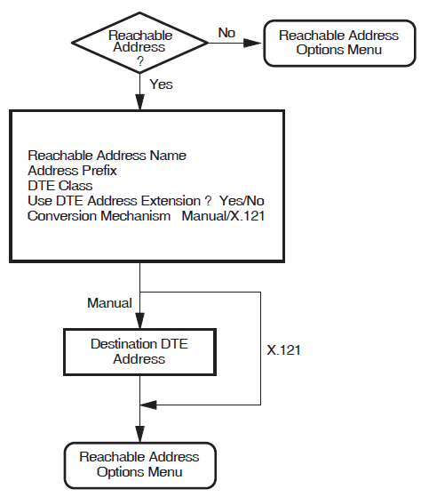
8.16. X.25 Server–Clients Section
Figure 8.14, ''X.25 Server–Clients'' illustrates the X.25 Server–Clients Section.
The X.25 Server–Clients Section allows you to set up a number of X.25 Server–Clients that represent the server's Client systems.
You must specify at least one service node and at least one filter for each X.25 Server–Client. Incoming calls are handled by an X.25 Server–Client only if they match one of that Server–Client's filters. The X.25 Server–Client then uses the service node information to contact the Client system.
Service Node
You must specify at least one service node for each X.25 Server–Client.
When creating an X.25 Server–Client you can include a number of service nodes. To add, modify, or delete service nodes associated with an existing X.25 Server–Client, select the "Modify" option on the X.25 Server–Client Options Menu.
Filters
You must specify at least one unique filter for each X.25 Server–Client. The Filter Name and Priority fields are mandatory; all other fields are optional.
When creating an X.25 Server–Client, you can create a number of filters. To add, modify, or delete filters associated with an existing X.25 Server–Client, select the "Modify" option on the X.25 Server–Client Options Menu.
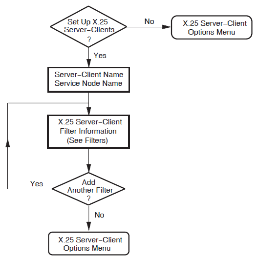
8.17. Security
Caution
VSI strongly recommends that you set up both incoming and outgoing security to protect your system from unauthorized use.
Create or Modify X.25 Security
This option allows you to define incoming security for applications and filters, and to define outgoing security for local processes. Selecting this option displays the first of the security sections.
Allow outgoing X.25 calls only
This option allows all outgoing calls to be made from your system, but does not allow incoming calls. Selecting this option bypasses the incoming and outgoing security sections and displays the NCL Script Section.
Allow all X.25 calls
This option leaves security open, that is, no security is applied to incoming or outgoing calls. Selecting this option bypasses the incoming and outgoing security sections and displays the NCL Script Section.
8.18. Incoming Security: Applications
Figure 8.15, ''Incoming Security: Applications '' illustrates the Incoming Security: Applications Section.
This section allows you to specify the type of incoming access for each application you specified. You must complete this section if you want Applications to receive incoming calls.
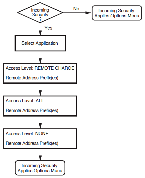
8.19. Incoming Security: Filters
Figure 8.16, ''Incoming Security: Filters '' illustrates the Incoming Security: Filters Section.
This section allows you to specify the type of incoming access for the Filters specified. You must complete this section if you want Filters to be able to receive incoming calls.
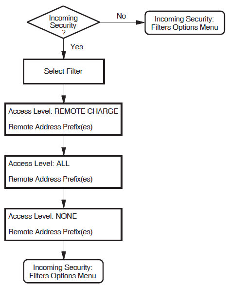
8.20. Incoming Security Section: X.25 Relay–Clients
Figure 8.17, ''Incoming Security: Relay Clients'' illustrates the Incoming Security Section for X.25 Relay–Clients. This section allows you to specify remote DTEs and the related type of incoming access to the specified X.25 Relay–Client.
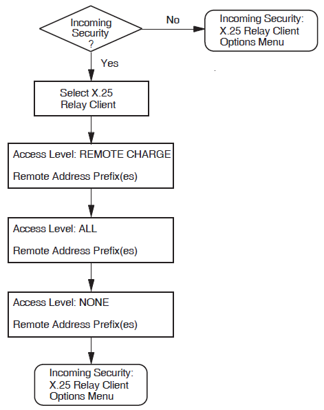
8.21. Outgoing Security: Local Processes
Figure 8.18, ''Outgoing Security: Local Processes'' illustrates the Outgoing Security: Local Processes Section.
You must complete this section if you want processes on this system to be able to make outgoing calls. Processes include X.25 applications.
For X.25 applications, enter the name of the group to which the process belongs when prompted for the Rights Identifier.
$set def sys$system$run authorizeUAF>show /identifier *
If the rights identifier you enter does not exist, it will be defined before you exit the
configuration program provided that you select to run
the command procedure SYS$SYSTEM:X25$SECURITY_IDENTIFIERS.COM.
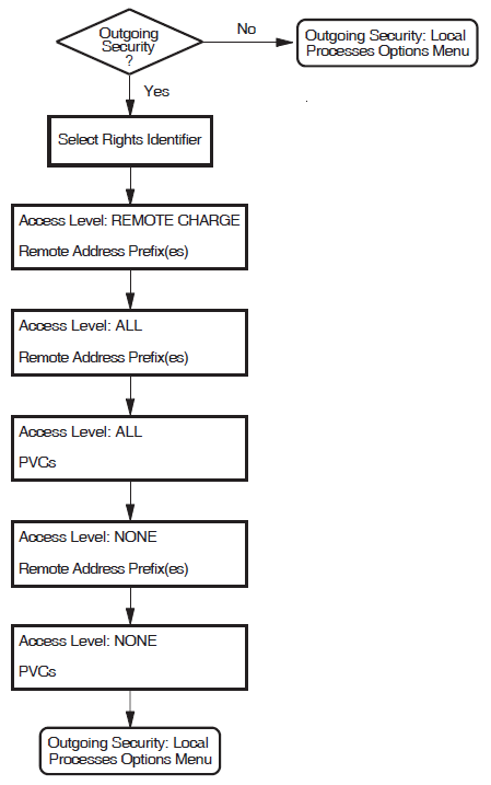
8.22. NCL Script
Figure 8.19, ''NCL Script'' illustrates the NCL Script Section.
When you reach this section, you have entered sufficient information to create a working X.25 configuration. If you want to verify some of the information you have entered, or add or delete some information, then answer No to the question "Do you want to create an NCL script now?" You will then go back to the Sections Menu, from which you can choose the section you want to review.
When you are sure that the information you have entered is correct and complete, display the Sections Menu and select the option Create the NCL Script.
If the program creates the configuration file, a message is displayed which indicates the filename assigned to the file.
If, for some reason, the program cannot create the NCL script, error messages are displayed at the foot of the screen. If this occurs, you must correct the problem before making a further attempt to create the NCL script.
If you have configured the Remote DTE Classes Section, the configuration program now displays the number of Session Connections that can be established based on the configuration you have defined. You must ensure that the NSP attributes Maximum Transport Connections and Maximum Remote NSAPs are large enough to support this number of session connections. The default values of these attributes are 200 and 201 respectively.
Exit the configuration program.
Use NCL to disable the NSP entity.
Make the required NSP attribute changes.
Enable the NSP entity.
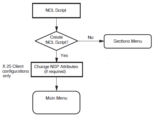
Chapter 9. Verifying the Configuration
This chapter explains how to run the Configuration Test Procedure (CTP) to verify the configuration created.
The CTP verifies that the product has been installed and configured correctly. It also verifies that the basic operations of X.25 connections, such as data transfer to and from the node, have been tested.
The CTP consists of a screen–based verification procedure. The procedure prompts for information about any DTEs or PVCs you want to test.
After installing, rebuilding, and configuring X.25, run the CTP to verify that the software installed is correctly configured on your system. You might also want to run the CTP after a system failure to be sure that users can access X.25.
9.1. Testing Your Configuration
You can run the CTP either in loop back mode (from your system through the PSDN and back to your system), or to a remote system through the PSDN.
9.2. Preparing to Run the CTP
This section describes the privileges and system quotas required, and the actions that must be taken, before you can run the CTP.
Privileges Required
System Quotas Required
Rights Identifiers Required
When CTP is initialized, users are given the rights identifier PSI$X25_USER. This privilege should be sufficient. If this provides insufficient privileges to run CTP, assign the BYPASS privilege.
X.25 for OpenVMS Software
X.25 for OpenVMS must be configured and running on your system.
- The DTE you want to use to make and receive calls must be up and running. Use the following commands to verify this (at the Connector node if testing an X.25 Client system):
ncl>show x25 protocol dte-name stateIf the status of the DTE is not shown as
Running, wait for two minutes and try again. If the status of the DTE is still notRunning, refer to the VSI X.25 for OpenVMS Problem Solving.
Partner System
Partner systems may be either the local system running the CTP or an accessible X.25 for OpenVMS system correctly configured to allow access from the local system and running CTP in Receive–Only mode.
You must know the X.25 address of the partner system.
9.3. Running the CTP
You can run the CTP can either interactively or as a network object (that is, a predefined X25 ACCESS APPLICATION entity).
9.3.1. Running the CTP Interactively
$ run sys$test:x25$ctpAfter some introductory screens, you are asked which mode you want to run the CTP in (Send/Receive mode, Receive–Only mode, or Send–Only mode). Full details of these modes are given in Section 9.4, ''CTP Test Modes''.
9.3.2. Running the CTP as a Network Object
$ @sys$test:x25$ctp_add_netobjX25$STARTUP.COM.Note
When the CTP is set up as a network object, it can only handle incoming calls (either from a remote system or calls that have been looped back from the PSDN).
$ @sys$test:x25$ctp_rem_netobj9.4. CTP Test Modes
Receive–Only mode—allows you to test your system's ability to receive incoming calls from remote systems.
Send–Only mode—allows you to test your system's ability to send calls to a remote system that is running the CTP in Receive–Only mode.
Send/Receive mode—allows you to test your system's ability to communicate with a PSDN (loopback testing) or with a remote system running the CTP in Receive–Only mode.
Full details about each of these modes are given in Sections 9.4.1, 9.4.2, and 9.4.3 respectively.
9.4.1. Receive–Only Mode
Receive the X.25 connection requests from the other node
Set up PVCs as test receivers
Display testing information in the event of failure
Restrictions
These nodes do not initiate any tests. This is performed by nodes running the Send–Only or Send/Receive mode.
You are not allowed to run more than one Receive–Only mode at a time on any machine
The Receive–Only mode should be run first.
Note
Do not exit the Receive–Only mode until testing has been completed by the CTP in Send/Receive mode on the remote system,otherwise receiving will be disabled.
9.4.2. Send–Only Mode
Initiate connection requests and transfer of data
Provide diagnostic and error messages
When running X.25 for OpenVMS, the Send–Only mode initiates the testing of DTEs and accesses connections to server nodes of the node on which it is run.
9.5. Testing SVCs and PVCs
Figure 9.1, ''Configuration Test Procedure Flowchart'' provides a flowchart of the testing procedure for testing of SVCs and PVCs. For details of the steps required to test SVCs and PVCs, refer to Sections 9.5.1 through Section 9.5.3, ''Testing Remote SVCs''. A summary of the tests performed on each SVC or PVC are provided in Section 9.5.4, ''Test Summary''.
Note that at the end of testing you are prompted whether to repeat any of the tests. If during the initial testing you chose to set up PVC receivers, those receivers are used for any repeat testing.
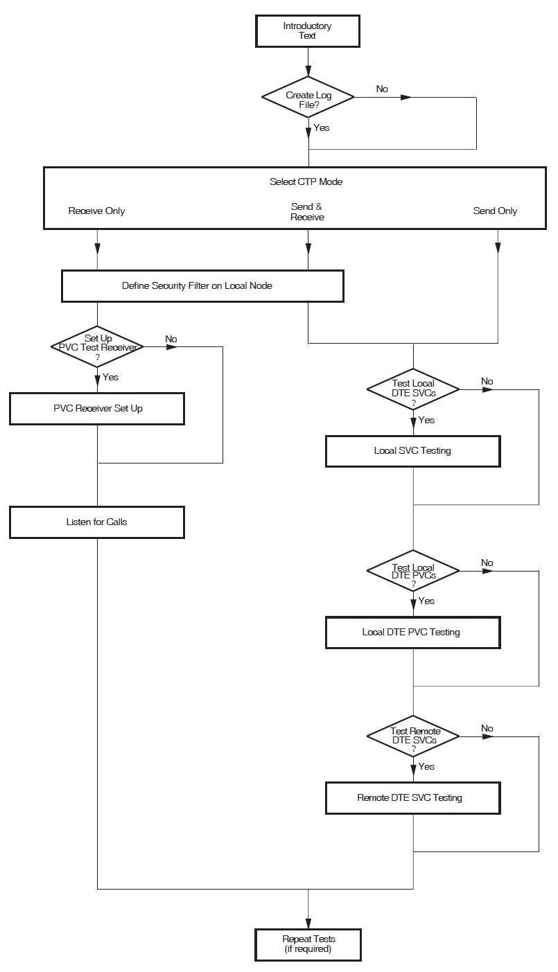
9.5.1. Testing Local SVCs
First, you are asked if you want to carry out local SVC testing (that is, local DTE class testing).
The security filter name (if Send/Receive or Receive–Only mode is being used) The default is the first security filter in the list shown.
A default destination X25 address to which the test connection is to be made. The default is to use the DTE address defined for the local DTE.
                       LOCAL DTE SVC TESTING
DTE            Usable  Test  DTE Class      Dest Addr  Result
---            ------  ---   ---------      ---------  ------
LLC2-LCL-REM1  Yes     Yes   LLC2-LCL-REM1  12345
LLC2-LCL-REM2  Yes     Yes   LLC2-LCL-REM2  6789
LLC2-LCL-REM3  Yes     Yes   LLC2-LCL-REM3  9876
Default Destination Address
If you are using the local system as both the sender and the receiver, you cannot use a single local DTE as a common partner address to verify a number of local DTEs. This is because the CTP enables only the DTE being tested and the remaining local DTEs are disabled. Therefore, do not specify a default DTE address but instead take the supplied default for each local DTE (which is the address of the DTE under test) and perform the test in loopback mode.
After selecting the DTEs you want to test and entering the destination addresses, you are prompted whether you want to change any of the test information prior to performing the tests.
You may test as many DTEs as you want to. After the DTEs have been tested the system displays
either Success or Fail as the result of the test for each
DTE.
                    LOCAL DTE SVC TESTING
   DTE            Usable  Test  DTE Class         Dest Addr        Result
   ---            ------  ---   ---------         ---------        ------
   LLC2-LCL-REM1  Yes     Yes   REMCLASS-0        12345            Success
   LLC2-LCL-REM2  Yes     Yes   REMCLASS-1        12345            Success
   LLC2-LCL-REM3  Yes     Yes   REMCLASS-2        9876             Fail
         LOCAL DTE SVC TEST FAILURE
         DTE Class        Failure Analysis
         ---------        ----------------
         REMCLASS-0       Test:   SVC outgoing call test
                          Reason: Unsolic MSG$_DISCON mbx msg received
                                  cause code = 00, diag code = 00
                          Cause:  Call cleared unexpectedly
                          Action:
After reading the diagnostics and rectifying the problem, run the CTP test on the DTEs again.
9.5.2. Testing Local PVCs
After you have completed local SVC testing, you are prompted whether to test local PVCs. The X.25 Client Configuration Test Procedure allows you to test remote PVCs.
Defining PVC Receivers
If you are running the CTP in Send/Receive or Receive–Only mode, you are prompted for the names ofPVCs you want to use as test receivers.
                       PVC RECEIVER SET UP
                 PVC              Test   DTE Class        Result
                 ---              ----   ---------        ------
                 CLASSA-RCV       Yes    CLASSA
                 AUSNAC-RCV       Yes    AUSNAC
You must then enter the DTE class to which the PVC belongs. If the logical name PSI$NETWORK is defined on your system, the definition is used as the default DTE class name.
          PVC RECEIVER SET UP
                 PVC           Test   DTE Class        Result
                 ---           ----   ---------        ------
                 CLASSA-RCV    Yes    CLASSA           Fail
AUSNAC-RCV Yes AUSNAC Success PVC RECEIVER FAILURE
PVC Failure Analysis
--- ----------------
CLASSA-RCV Reason: Failed to set up receiver
status = SS$_IVDEVNAM
2nd status = PSI$C_ERR_NOSUCHPVC
Cause: Specified PVC is not known
Action: The entity you specified does not exist.
Ensure that the name was entered correctly in
the test data. To determine which entities are
configured, use the ncl command:
ncl> show x25 proto dte <dte-name> pvc * name
at the remote nodeAfter reading the diagnostics and rectifying the problem, run the CTP test on PVC receivers again.
Defining PVC Senders
If you are running the CTP in Send/Receive or Send–Only mode, you are prompted for the names of PVCs you want to test. Enter only the names of PVCs for which receivers have been successfully set up using the CTP.
The same tables are displayed as for PVC receiver setup. When prompted, enter the DTE class to which the specified PVCs belong.
The results are displayed as they were for the PVC receivers.
9.5.3. Testing Remote SVCs
Lastly, you are asked if you want to carry out remote SVC testing (that is, testing remote DTE classes).
The security filter name (if Send/Receive or Receive–Only mode is being used)
A default destination X25 address to which the test connection is to be made
                             REMOTE DTE SVC TESTING
                DTE Class         Test   Dest Addr        Result
                ---------         ----   ---------        ------
                REMCLASS-0        Yes    12345
                REMCLASS-1        Yes    9876
Default Destination Address
When running the CTP to verify a number of remote DTE classes, you can use the same remote DTE, running the CTP in Receive–Only mode, as a common partner for each of the remote DTE classes. In this case, the DTE address of the partner system may be specified as a Default Destination Address to avoid having to specify it repeatedly.
You are then prompted whether to change any of the test information prior to performing the tests.
You may test as many DTE classes as you want to. After the remote DTE classes have been
tested, the system displays either Success or Fail as the
result of the test for each DTE class.
                         REMOTE DTE SVC TESTING
                DTE Class         Test   Dest Addr        Result
                ---------         ----   ---------        ------
                REMCLASS-0        Yes    12345            Fail
REMCLASS-1 Yes 9876 Success REMOTE DTE SVC TEST FAILURE
DTE Class Failure Analysis
--------- ----------------
REMCLASS-0 Test: SVC outgoing call test
Reason: Unsolic MSG$_DISCON mbx msg received
cause code = 00, diag code = 00
Cause: Call cleared unexpectedly
Action:After reading the diagnostics and rectifying the problem, run the CTP test on the DTEs again.
9.5.4. Test Summary
SVC outgoing call test or PVC access test
Reset test
Interrupt test
Write/read test
Reset test
Interrupt test
Write/read test
SVC outgoing clear test or PVC deaccess test
If all the tests succeed the system displays Success as the result of the test.
Otherwise, the system displays Fail, and the results of the first test
which failed are displayed in detail.
9.6. CTP Failure Reasons
A specific test fails
The CTP exits
These events and how to proceed if one occurs are described in Sections 9.6.1 and 9.6.2 respectively.
9.6.1. Test Failure
The operation being performed when the error occurred
The system message associated with the error
An X.25–specific reason for the error and, where relevant, details of the action that should be taken to rectify the error
9.6.2. CTP Exits
If the CTP is unable to run on your system it exits with an error message. Table 9.1, ''CTP Errors'' details each of the error messages that may be displayed and the action that should be taken to rectify the problem.
x25$pr file not found | |
|
Reason: |
The executable for the receiver process could not be found. |
|
Action: |
Ensure that the file |
no connection to X25$PR – timed out trying to connect to x25$pr – | |
|
Reason: |
The CTP could not connect to the receiver process. |
|
Action: |
Ensure that when the CTP is running, the process X25$PR_PID is also running on the local system, and either X25$PR_PID or PSI$PR is running on the receiving system. |
version mismatch between X25$PR interface and X25$PR – x25$ctp and x25$pr images not compatible – | |
|
Reason: |
The sending and receiving processes have different protocol versions. You cannot use this version of the X.25 for OpenVMS CTP to communicate with a system that produces these messages. |
|
Action: |
Use loopback testing if a remote system running X.25 for OpenVMS V1.0 or later is not available. |
x25$pr has no room for new connections | |
|
Reason: |
The limit for connections to the receiver process has been exceeded. |
|
Action: |
Reduce the number of CTP processes trying to connect to this receiver process, and/or the number of circuits being tested at one time. The maximum number of connections permitted is 16. |
invalid X.25 Client installation | |
|
Reason: |
Your X.25 Client license has either expired or has been deregistered. |
|
Action: |
The license must be loaded and registered before X.25 Client or the CTP can be used. |
X.25 Client not running | |
|
Reason: |
X.25 Client is installed but not running. |
|
Action: |
Ensure that X.25 client has been started. |
invalid receiving mode | |
|
Reason: |
The logical PSI$PR_NETOBJ_MODE has been defined incorrectly. |
|
Action: |
Issue the DCL command: If the logical name is defined, it must be either SINK or MIRROR. Any other value is invalid. |
exceeded <quota type> quota | |
|
Reason: |
The system quota for the type specified has been exceeded. |
|
Action: |
Use |
Chapter 10. Modifying the Configuration
This chapter describes how to modify an existing X.25 for OpenVMS configuration.
10.1. Overview of Methods
Re–run the configuration program to generate a new configuration file, based on the existing configuration. Refer to Section 10.2, ''Using the Configuration Program''.
Add NCL commands to, or edit existing NCL commands in, the available user NCL script files. The NCL commands in these files are executed in addition to the NCL commands executed by the startup script. Refer to Section 10.3, ''Editing the User NCL Script Files''.
Enter NCL commands to dynamically change the configuration. Refer to Section 10.4, ''Modifying a Configuration Dynamically''.
Discard the current configuration data entirely and create a new configuration. This method is detailed in Section 10.5, ''Discarding a Configuration''.
If you run the configuration program to make the changes required, the NCL script generated contains the required configuration data. Whenever the system is started up, the NCL script is run to configure the system.
If you add NCL commands to, or edit NCL commands in, the user NCL script files, the commands are executed when the startup script is next run.
- If you change the configuration dynamically by issuing NCL commands, those changes remain in effect until one of the following actions take place:
The commands are revoked by subsequent NCL commands.
The system reboots and uses the configuration file NCL commands.
The configuration program is re–run (to generate a new configuration file) and the system is then rebooted.
10.2. Using the Configuration Program
Note
The configuration program does not permit you to use BASIC mode to modify a configuration that was originally created using ADVANCED mode. This ensures that configuration data entered using the ADVANCED mode is retained for future use.
Invoke the configuration program in BASIC or ADVANCED mode. Refer to Chapter 2, "Using the Configuration Program".
Select the option "Modify an existing configuration script" from the Main Menu.
The configuration program retrieves the information stored in the configuration database.If the program is invoked in BASIC mode, it will load the information stored in the file
SYS$STARTUP:X25$BASIC_CONFIG.DAT.If the program is invoked in ADVANCED mode, it determines whether configuration data exists that was entered using the ADVANCED mode, that is, whether the file
SYS$STARTUP:X25$CONFIG.DAThas been created. If this file does notexist, the configuration program loads the data from the fileSYS$STARTUP:X25$BASIC_CONFIG.DAT.
Once the configuration data has been loaded, the Section Menu is displayed.
Use the options on the Section Menu to modify, add to, or delete the previously entered data.
Caution
If you have dynamically changed the configuration by issuing NCL commands interactively, the changes made will be lost when the startup script is next run.
If you select to modify the configuration by mistake or while modifying the configuration decide that you want to revert to the previous configuration, press F8 before selecting the option to create the NCL script. Modifications to a configuration are saved only if you select to create the NCL script and that script is used when the startup script is next run.
10.3. Editing the User NCL Script Files
Four user NCL script files are created the first time the configuration program is run. These script files can be used to contain user–supplied NCL commands. The script files are called when the startup script is invoked and any commands defined in them are used to augment the NCL commands in the master NCL script file generated as a result of running the configuration program.
SYS$STARTUP:X25$EXTRA_CREATE.NCL |
File containing additional, user–supplied NCL commands specific to creating entities. |
SYS$STARTUP:X25$EXTRA_ENABLE.NCL |
File containing additional, user–supplied NCL commands specific to enabling entities. |
SYS$STARTUP:X25$EXTRA_SECURITY.NCL |
File containing additional, user–supplied NCL commands specific to security. |
SYS$STARTUP:X25$EXTRA_SET.NCL |
File containing additional, user–supplied NCL commands specific to setting the values of entities. |
A standard text editor can be used to add NCL commands to these script files. Each command should be placed on a separate line. Only valid NCL commands should be added to the script files.
ncl> do script-filenameSYS$STARTUP:X25$EXTRA_CREATE.NCLSYS$STARTUP:X25$EXTRA_ENABLE.NCLSYS$STARTUP:X25$EXTRA_SECURITY.NCLSYS$STARTUP:X25$EXTRA_SET.NCL
Note
The current configuration may have enabled one or more of the entities affected by commands specified in the user NCL script files. Such entities will have to be disabled before the user NCL script files can be executed successfully.
10.4. Modifying a Configuration Dynamically
To modify an existing configuration dynamically, use NCL commands to alter the configuration parameters initially set up when the configuration file is run. Full details on how to use NCL are given in the VSI DECnet–Plus for OpenVMS—Network Control Language Reference manual.
10.5. Discarding a Configuration
If you want to discard your existing configuration or make extensive modifications to your configuration, it may be more efficient to create an entirely new configuration. This can be achieved by invoking the configuration program and selecting the Create option from the Main Menu.
The existing configuration is superseded when the new configuration file is generated.
10.6. Reusing a Saved Configuration File
Whenever a configuration file is generated by the configuration program, the previous script (if any) is saved. Provided that you have not manually deleted a saved version, a specific version can, if required, be recalled and used in place of the current version.
Rename the required version of the
X25$CONFIG.NCL_SAVfile toX25$CONFIG.NCL.Boot the system.
$ rename x25$config.ncl_sav;3 x25$config.nclAppendix A. Values Specific to Your Configuration
This Appendix provides of a set of blank tables in which you can record the configuration parameter values specific to your system. You can then refer to these tables when you run the configuration procedure.
Section A.1, ''Basic Mode Configuration Parameter Values'' provides tables specific to the BASIC mode of the configuration program.
Section A.2, ''Advanced Mode Configuration Parameter Values'' provides tables specific to the ADVANCED mode of the configuration.
Note that there is some overlap between the data required for each mode of operation.
|
Forms for the BASIC Mode: | |
|
X.25 over Wide Area Network | |
|
X.25 over Local Area Network | |
|
X.25 Client | |
|
PVCs | |
|
Incoming Call Security | |
|
X.29 Support | |
|
Forms for the ADVANCED Mode: | |
|
Remote DTE Classes | |
|
Lines and DTEs | |
|
LLC2 DTEs | |
|
XOT DTEs | |
|
Session Connections | |
|
PVCs | |
|
Groups | |
|
X.29 Support | |
|
Applications | |
|
Relay Clients | |
|
Filters | |
|
Templates | |
|
Reachable Address | |
|
Server Clients | |
|
Incoming Security: Applications | |
|
Incoming Security: Filters | |
|
Incoming Security: Relay Clients | |
|
Outgoing Security: Local Processes | |
A.1. Basic Mode Configuration Parameter Values
Information required | Your values |
|---|---|
Profile name |
|
X.25 address |
|
Synchronous line name |
|
Incoming Logical Channel Ranges |
|
Outgoing Logical Channel Ranges |
|
Information required | Your values |
|---|---|
LAN device name | |
X.25 DTE address | |
LAN remote host names ? | |
Remote MAC address | |
Incoming Logical Channel Ranges | |
Outgoing Logical Channel Ranges |
Information required | Your values |
|---|---|
Network name (remote DTE class) | |
X.25 Connector node names |
Information required | Your values |
|---|---|
DTE name (LAN configurations only) ? | |
PVC names | |
Channel numbers |
Information required | Your values |
|---|---|
Security type (Allow all incoming access Allow no incoming access Restricted incoming access) | |
|
If Restricted Incoming Access: | |
Remote DTE addresses with | |
Access level = Remote Charge | |
Remote DTE addresses with | |
Access level = All | |
Information required | Your values |
|---|---|
X29 Network User Identity |
A.2. Advanced Mode Configuration Parameter Values
Information required | Your values |
|---|---|
DTE class name | |
Outgoing session template | |
Segment size | |
X.25 Connector node names |
Information required | Your values |
|---|---|
Line name | |
Line speed | |
Link name | |
DTE name | |
X.25 address | |
Profile name | |
DTE interface type (DTE, DCE, or Negotiated) | |
Incoming Logical Channel Ranges | |
Outgoing Logical Channel Ranges | |
Packet level negotiation (Yes or No) | |
Extended packet sequence numbering (Yes or No) | |
Minimum packet size | |
Maximum packet size | |
Default packet size | |
Level 3 minimum window size | |
Level 3 maximum window size | |
Level 3 default window size | |
Extended frame sequence numbering (Yes or No) | |
Level 2 window size | |
Level 2 maximum data size | |
Link interface type (DTE or DCE) | |
Segment size | |
Inbound DTE class |
Information required | Your values |
|---|---|
LAN device name | |
LLC2 DTE name | |
LLC2 DTE address | |
Local LSAP address | |
Level 3 Profile | |
Incoming Logical Channel Ranges | |
Outgoing Logical Channel Ranges | |
Remote MAC address | |
Remote LSAP address | |
Link Interface type (DTE, DCE, or Negotiated) | |
Packet level negotiation (Yes or No) | |
Extended packet sequence numbering (Yes or No) | |
Minimum packet size | |
Maximum packet size | |
Default packet size | |
Level 3 Minimum window size | |
Level 3 Maximum window size | |
Level 3 Default window size | |
Inbound DTE Class |
Information required | Your values |
|---|---|
Local TCP/IP address | |
XOT DTE name | |
XOT DTE address | |
Local RFC1613 port number | |
Level 3 profile | ISO8881 |
Incoming Logical Channel Ranges | |
Outgoing Logical Channel Ranges | |
Remote TCP/IP address | |
Remote RFC1613 port number | |
Packet level negotiation (Yes or No) | |
Minimum packet size | |
Maximum packet size | |
Default packet size | |
Level 3 minimum window size | |
Level 3 maximum window size | |
Level 3 default window size | |
Inbound DTE class |
Information required | Your values |
|---|---|
Maximum Session Control Connections |
Information required | Your values |
|---|---|
DTE name | |
PVC name | |
Channel number | |
Packet size | |
Window size |
Information required | Your values |
|---|---|
Group name | |
Group type (CUG, BCUG, or CUGOA) | |
DTE names | |
Corresponding CUG numbers | |
Remote DTE address (BCUG Only) |
Information required | Your values |
|---|---|
X.29 Network User Identity | |
DTE class for outgoing X.29 calls |
Information required | Your values |
|---|---|
Name | |
Type (X.25 or X.29) | |
Command file to start application | |
Username for application | |
Template name (X.29 applications only) | |
Template details (refer to Table A.18, ''Templates'') | |
Filter names | |
Filter details (refer to Table A.17, ''Filters'') |
Information required | Your values |
|---|---|
Client name | |
DTE class | |
Template name | |
Filter names |
Information required | Your values |
|---|---|
Name | |
Priority | |
Incoming DTE address | |
Call data mask | |
Call data value | |
DTE class | |
Sending DTE address | |
Receiving DTE address | |
Group name | |
Originally called address | |
Redirect reason | |
Called address extension mask | |
Called address extension value | |
Called NSAP |
Information required | Your values |
|---|---|
Name | |
DTE class | |
Call data | |
Packet size | |
Window size | |
Destination DTE address | |
Fast select option | |
Reverse charging (Allow or Do not allow) | |
Selected group | |
Throughput class request | |
Network User Identity | |
Local facilities | |
Charging information (Display or Do not display) | |
RPOA sequence | |
Local subaddress | |
Target address extension | |
NSAP mapping (Yes or No) | |
Calling address extension | |
Transit delay selection | |
End-to-end delay | |
Expedited data option (Use, Do not use, or Not specified) |
Information required | Your values |
|---|---|
Name | |
Address prefix | |
DTE class | |
Address extensions (Yes or No) | |
Conversion mechanism (X.121 or Manual) | |
Destination DTE address (only for Manual) |
Information required | Your values |
|---|---|
Client name | |
Service nodes | |
Filter names |
Information required | Your values |
|---|---|
Name | |
DTE addresses, Access = Remote Charge | |
DTE addresses, Access = All | |
DTE addresses, Access = None |
Information required | Your values |
|---|---|
Name | |
DTE addresses, Access = Remote Charge | |
DTE addresses, Access = All | |
DTE addresses, Access = None |
Information required | Your values |
|---|---|
Name | |
DTE Addresses, Access = Remote Charge | |
DTE Addresses, Access = All | |
DTE Addresses, Access = None |
Information required | Your values |
|---|---|
Rights identifier | |
DTE addresses, Access = Remote Charge | |
DTE addresses, Access = All | |
PVC names, Access = All (only required if PVCs configured) | |
DTE addresses, Access = None | |
PVC names, Access = None (only required if PVCs configured) |
Appendix B. X.25 Communication Methods for OpenVMS IA-64 Systems
GAP (X.25 over DECnet)
LLC2 (X.25 over LAN)
XOT (X.25 over TCP/IP)
These methods require an external machine to act as a gateway or relay to the X.25 connection or PSDN. This machine provides the interface for the actual synchronous line and may be implemented using an OpenVMS Alpha system with a PBXDP or PBXDD synchronous communication controller, or a third party dedicated router.
X.25 native communication using a synchronous communication controllers on OpenVMS IA-64 system will not be supported.
B.1. X.25 Server/Client
This communication method allows systems that are interconnected via a DECnet network to exchange X.25 protocol information. A typical network configuration would consist of an OpenVMS Alpha system with a synchronous communication controller (PBXDP or PBXDD) that would act as a gateway or X.25 Server for other OpenVMS Alpha or IA-64 systems (X.25 clients) running X.25.
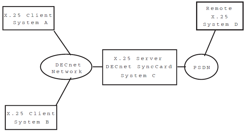
In this configuration, Systems A, B and C could communicate with System D. System C could be implemented as an Alpha system with a synchronous communication controller PBXDP or PBXDD, or as a third party router that supports X.25 Server (X.25 over DECnet) and synchronous communications.
Advantages of this configuration are that since DECnet is a routable protocol,the systems may be interconnected over wide area network. In addition, the actual networking backbone could be provided by TCP/IP and then use DECnet-over-TCP/IP for the X.25 client/server connection. One disadvantage for this configuration is that DECnet and X.25 Server/Client are implemented with proprietary protocols.
B.2. X.25 over Ethernet (LLC2)
Pure LLC2
LLC2 used in conjunction with a relay system which allows X.25 traffic to be "relayed" from the LLC2 link to some other linkage such as a sync card.
Both configurations are outlined in the following diagram:
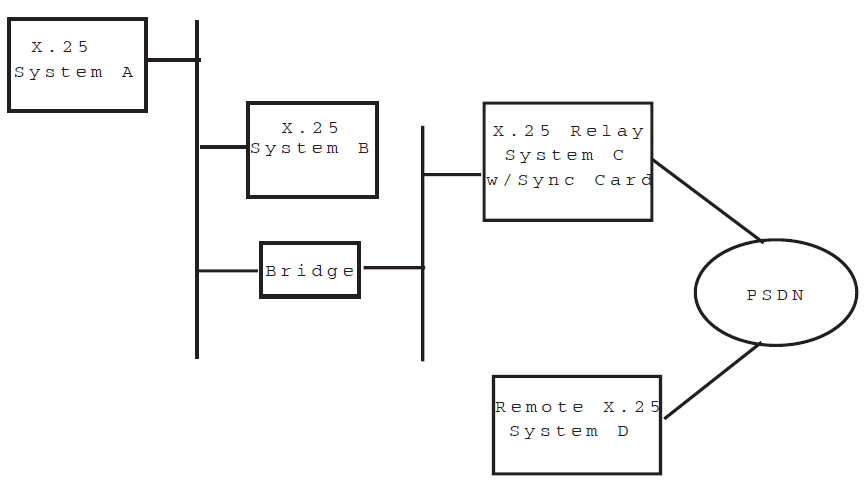
In the configuration shown, System A can communicate with System B using X.25 over LLC2. Both System A and B could also communicate with System C, and if System C was configured with X.25 Relay, Systems A and B would also be able to communicate with System D.
System C could be implemented as an Alpha system with a synchronous communication controller PBXDP or PBXDD, or as a third party router that supports LLC2 and synchronous communications.
The Relay system can be configured with different types of connections such as the synchronous line shown, or by running X.25 over TCP/IP. Many different types of third party router hardware exists that can provide the functionality of System C. LLC2 is not a routable protocol and so is limited to use on a LANor Extended LAN.
B.3. X.25 over TCP/IP (XOT)
Based on RFC1613, X.25 over TCP/IP (aka XOT), this communication method allows systems that are interconnected via TCP/IP network to exchange X.25 protocol information. A typical network configuration would consist of an OpenVMS Alpha system with a synchronous communication controller (PBXDP or PBXDD) that would act as a gateway or X.25 Server for other OpenVMS Alpha or IA-64 systems(X.25 clients) running X.25.
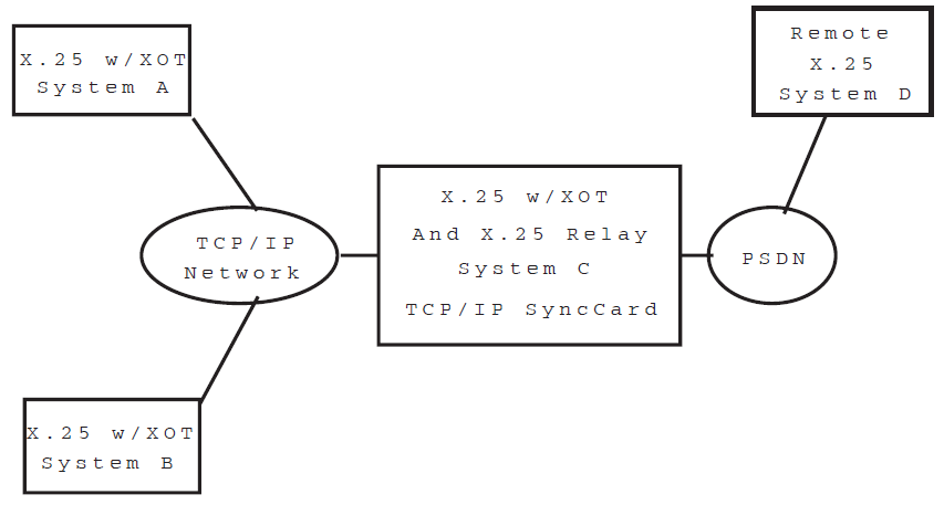
In this configuration System A can communicate via X.25 with System B; either A or B can communicate with System C which in turn could be configured with X.25 Relay allowing A & B to communicate with system D.
System C could be implemented as an Alpha system with a synchronous communication controller PBXDP or PBXDD, or as a third party router that supports X.25 over TCP/IP and synchronous communications.
Advantages of this configuration are that since TCP/IP is a routable protocol,the systems may be interconnected over wide area network. As with LLC2, there are many vendors that provide XOT functionality in dedicated routers. The connectivity between System C and System D could be via a synchronous line/PSDN; a point to point connection (leased line) or even an ISDN connection(using a dedicated device to connect from the sync line to an ISDN interface.
B.4. Variations on a theme
The following diagram looks at 2 disjoint locations (a home office and a remote office), connected via a virtual private network (such as PPTP).
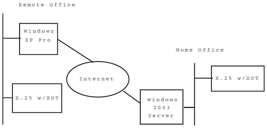
In this configuration the Windows XP Pro system would establish a PPTP connection to the Windows 2003 Server (or even another XP Pro system). Once the VPN connection was established (and assuming that the Windows systems were configured for internet connection sharing), the two X.25 systems running XOT could communicate.
The major advantage of this configuration is that it completely eliminates the need for a synchronous communication adapter. The configuration is also very secure, since the PPTP connection can have 128 bit encryption. The existing X.25 legacy application to continue functioning with no noticeable change (from the application perspective) to the network environment.
Appendix C. Example Configurations
Example A details a configuration in which X.25 is set up to run over a synchronous link, with X.29 and X.25 applications configured to run over the network. Refer to Section C.1, ''Example A – Configuration of X.25 Over a Synchronous Link''.
Example B details a configuration in which X.25 is set up to run over LLC2, with X.29 and X.25 applications configured to run over the network. Refer to Section C.2, ''Example B – Configuration of X.25 Over LLC2''.
Within each example, details are provided of the values that need to be entered in each section of the X.25 configuration program to configure the example system. Where appropriate, notes are provided about the values specified. Both examples assume that the configuration program is being used in ADVANCED mode.
A system cannot be configured without due consideration to its security. For this reason, details of setting up adequate system security are provided for each example.
To enable values entered in each configuration section to be compared to the corresponding NCL commands created when the NCL Script is generated, an NCL Script for the configured X.25 system is provided at the end of each example. References to the appropriate sections in the NCL Script are provided within each documented configuration section.
C.1. Example A – Configuration of X.25 Over a Synchronous Link
Figure C.1, ''Example Configuration: X.25 Over a Synchronous Link'' shows the X.25 over LAPB configuration to be created. The X.25 for OpenVMS
system is to be connected to two PSDNs, Eirpac and Austpac, by
synchronous lines line-1 and line-2. It is assumed that the
lines were configured using wddsetup when the WAN Device Drivers subsets
were installed.
The networks contain remote X.25 hosts (having DTE addresses as shown) with which the X.25 for OpenVMS system is to communicate.
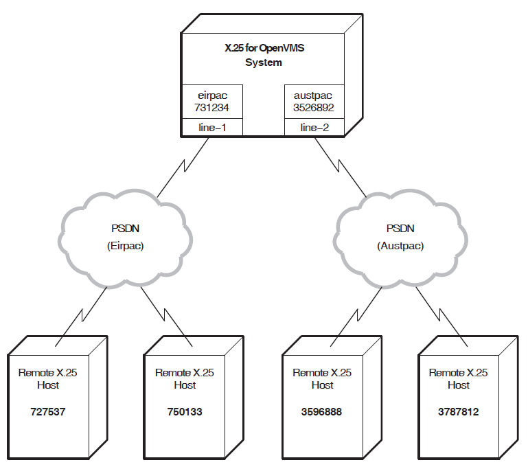
X.29 calls are to be allowed over the Eirpac network, but not over the Austpac network.
An X.25 application called
X25Demois to be set up for incoming X.25 calls from the Austpac network.
Security is to be configured to allow these calls to be verified.
Details of the entries that must be made in each configuration program section to create the required configuration are provided in the following subsections.
Lines and DTEs Section
- For
line-1, a DTE having the following values must be created:DTE Name:
eirpacDTE Address:
731234- Interface Type:
DTE- The Interface Type is set to DTE because the system is connected to a PSDN.
Profile:
EIRPACOutgoing List:
{[1..31]}Incoming List:{[1..31]}- The values for the Outgoing List and Incoming List
must be set to values appropriate to the host's
subscription for the specified network. The range of
permissible values is supplied by the network's
administrative body. In this example, the Outgoing List
and Incoming List for DTE
eirpacare both set to{[1..31]}.
- The values for the Outgoing List and Incoming List
must be set to values appropriate to the host's
subscription for the specified network. The range of
permissible values is supplied by the network's
administrative body. In this example, the Outgoing List
and Incoming List for DTE
- Local DTE Class:
EIRPAC.- This is the DTE class that applications will use to make outgoing calls to the network to which this DTE connects. The DTE class is also used for call security.
Other values: Default values loaded from the network profile.
- For
line-2, a DTE having the following values must be created:DTE Name:
austpacDTE Address:
3526892- Interface Type:
DTE- The Interface Type is set to DTE because the system is connected to a PSDN.
Profile:
AUSTPACOutgoing List:
{[3..32]}Incoming List:{[3..32]}- In this example, the Outgoing List and Incoming List
for DTE
austpacare both set to{[3..32]}.
- In this example, the Outgoing List and Incoming List
for DTE
- Local DTE Class:
AUSTPAC.- This is the DTE class that applications will use to make outgoing calls to the network to which this DTE connects. The DTE class is also used for call security.
Other values: Default values loaded from the network profile.
The NCL commands corresponding to the values entered in this configuration section appear in
the NCL script under the heading Create and set DTE: <dte-name>.
X.29 Support Section
- Network User Identity:
%x25abacab- The Network User Identity (NUI) is set to identify the party to
pay for the outgoing X.25 call made when an X.29 call is made from
this system. In this example, the NUI has been set to
%x25abacab.
- The Network User Identity (NUI) is set to identify the party to
pay for the outgoing X.25 call made when an X.29 call is made from
this system. In this example, the NUI has been set to
- DTE Class:
EIRPAC- This specifies that all outgoing X.29 calls are made over the Eirpac network.
Applications Section
Note
The X.25 application values are largely arbitrary, as they are dependent on the application being run, but the values specifying the network to send X.25 calls to, and receive X.25 calls from, are significant.
X25Demo must be created in the Applications Section with the
following values: Application Name:
X25Demo- Application Type:
X.25- This specifies that the application writes to the X.25 programming interface.
- Command File:
SYS$SYSTEM:X25DEMO.COM- The command file for this example application.
- User Name:
banks- The user ID of the application when handling X.25 calls. This determines the permissions the application possesses while being run.
- An Application Filter having the following values:
Filter Name:
x25demo_filterCall Data Mask:
%xffffffffCall Data Value:%x25abacab.- The Call Data can be used to select the application
to be run;
%x25abacab, in this example, selectsX25Demo.
- The Call Data can be used to select the application
to be run;
- Inbound DTE Class:
AUSTPAC.- This specifies that only incoming calls from the Austpac network will be accepted by this application.
Other values: Default values for X.25 filters.
The NCL commands corresponding to the values entered in this configuration section for the
application X25Demoappear in the NCL script under the heading Create
and set Application Entities. The NCL commands for its filter
x25demo_filter appear under the heading Create and set up X25
Access Filters.
Incoming Security: Applications Section
Incoming security for both X.29 calls and X.25 applications needs to be specified to allow
incoming X.29 calls and access to the application X25Demo. For this example
configuration, the following levels of security will be set up:
Remote X.25 host
727537will have no access. Users from that node will not be permitted to make X.29 calls to the X.25 for OpenVMS host.Remote X.25 host
750133will have unrestricted access. Users from that node will be permitted to make X.29 calls to the X.25 for OpenVMS host even if the remote host requests that the X.25 for OpenVMS host pays for the call.All other nodes on that network will have remote charge access. They will only be permitted X.29 access if they pay for it.
X25Demo:Remote X.25 hosts
3787812and3596888will have unrestricted access to X25Demo.All other nodes will have remote charge access to X25Demo.
- Incoming X.29 calls are represented by the application
X29_LOGIN. For this application,*is added to the list of Remote Address Prefixes with an access level of Remote Charge.750133is added to the list of Remote Address Prefixes with an access level of All.727537is added to the list of Remote Address Prefixes with an access level of None.
- For the
X25Demoapplication,*is added to the list of Remote Address Prefixes with an access level of Remote Charge.3787812and3596888are added to the list of Remote Address Prefixes with an access level of All.The list of Remote Address Prefixes with an access level of None is left empty.
The NCL commands corresponding to this security setup lie chiefly under the NCL Script
headings Create Security Filters and Create Remote DTEs.
Remote DTEs are created for each remote X.25 host specified, and rights identifiers are
attributed to them according to the level of access granted to that remote host by
different X.25 applications. Therefore, in the example NCL script, the remote DTE
remdte-0 has the remote address prefix set to 750133, and
has a rights identifier of APPL_X29_LOGIN_ALL. This indicates that the
remote host 750133 has All (unrestricted) access when calling this host
using X.29.
In the example NCL script, the remote DTE match_all has the remote address prefix
set to *, and has rights identifiers of APPL_X25Demo_REMOTE
and APPL_X29_LOGIN_REMOTE. This indicates that all remote hosts
except those with corresponding remote DTE entities have remote
charge access when accessing this node using X.29, or when accessing the application
X25Demo.
Outgoing Security Section
Processes with the
managersidentifier will have all access to all remote addresses.Processes with the
staffrights identifier will have all access to nodes750133and727537, and Remote Charge access to all other nodes.Processes with the
usersrights identifiers will have Remote Charge access to750133and727537and no access to other nodes.
- For processes with the
managersrights identifier:The list of Remote Address Prefixes having an access level of Remote Charge is left empty.
*,750133and727537are added to the list of Remote Address prefixes having an access level of All. The last two addresses must be specified, as they were given explicit incoming security in the previous section. Addresses3596888and3787812do not need to be specified, as outgoing X.29 calls can only be made over the Eirpac network.The list of Remote Address Prefixes having an access level of None is left empty.
- For processes with the
staffrights identifier:*is added to the Remote Address Prefixes having an access level of Remote Charge.750133and727537are added to the list of Remote Address Prefixes having an access level of All.The list of Remote Address Prefixes having an access level of None is left empty.
- For processes with the
usersrights identifier:750133and727537are added to the list of Remote Address Prefixes having an access level of Remote Charge.The list of Remote Address Prefixes having an access level of All is left empty.
*is added to the Remote Address Prefixes having an access level of None.
The NCL commands corresponding to the values entered in the Outgoing Security configuration section for the application
X25Demo appear in the NCL script under the heading
Create
                and set Application Entities.
The NCL commands corresponding to the specified security setup appear in the NCL script under the heading
Create Remote DTEs.
Note that remote DTEs are created for each remote X.25 host specified, and Access Control entries, which associate the level of access granted with each group, are placed in the ACL of the Remote DTE.
Therefore, in the example NCL script, the remote dte
remdte-0 has remote address prefix set to
750133, and has an ACL entry with an identifier of
managers and an access level of
All. This indicates that processes with the identifier
managers have unrestricted access when making a call to destination address
750133.
These values are sufficient to allow an X.29 and an X.25 application to operate over the configuration shown in Figure C.1, ''Example Configuration: X.25 Over a Synchronous Link''.
NCL Script for Example A
!
!
! X25 CONFIGURATION SCRIPT
! ================================
!
! This script was produced on: Thu Feb 7 14:35:38 2005
!
!
!
!
!
! Create the x25 access entity
!
!create node 0 x25 access
!
!
! Create the Default Security DTE Class Entity
!
!create node 0 x25 access security dte class Default
!
!
! Create the x25 protocol entity
!
!
create node 0 x25 protocol
create node 0 lapb
!
! Create and set DTE: eirpac
! and LAPB link: eirpac
! using Line: line-1
!
create lapb link eirpac profile "EIRPAC"
set lapb link eirpac physical line modem connect line line-1
set lapb link eirpac interface type dte
set lapb link eirpac maximum data size 131
set lapb link eirpac window size 7
!
!
! Create and set DTE: eirpac
! using Line: line-1
!
!
create x25 protocol dte eirpac profile "EIRPAC"
set x25 protocol dte eirpac link service provider lapb link eirpac
set x25 protocol dte eirpac inbound dte class EIRPAC
set x25 protocol dte eirpac x25 address 731234
set x25 protocol dte eirpac interface type negotiated
set x25 protocol dte eirpac segment size 64
set x25 protocol dte eirpac outgoing list {[1..31]}
set x25 protocol dte eirpac incoming list {[1..31]}
set x25 protocol dte eirpac default packet size 128
set x25 protocol dte eirpac default window size 2
!
! Create and set DTE: austpac
! and LAPB link: austpac
! using Line: line-2
!
create lapb link austpac profile "AUSTPAC"
set lapb link austpac physical line modem connect line line-2
set lapb link austpac interface type dte
set lapb link austpac maximum data size 270
set lapb link austpac window size 2
!
! Create and set DTE: austpac
! using Line: line-2
!
create x25 protocol dte austpac profile "AUSTPAC"
set x25 protocol dte austpac link service provider lapb link austpac
set x25 protocol dte austpac inbound dte class AUSTPAC
set x25 protocol dte austpac x25 address 3526892
set x25 protocol dte austpac interface type negotiated
set x25 protocol dte austpac segment size 64
set x25 protocol dte austpac outgoing list {[3..32]}
set x25 protocol dte austpac incoming list {[3..32]}
set x25 protocol dte austpac default packet size 128
set x25 protocol dte austpac default window size 2
!
! Create Local DTE Class: eirpac
!
create x25 access dte class eirpac type local
set x25 access dte class eirpac security dte class Default
set x25 access dte class eirpac local dtes (eirpac)
!
! Create Local DTE Class: EIRPAC
!
create x25 access dte class EIRPAC type local
set x25 access dte class EIRPAC security dte class Default
set x25 access dte class EIRPAC local dtes (eirpac)
!
! Create Local DTE Class: austpac
!
create x25 access dte class austpac type local
set x25 access dte class austpac security dte class Default
set x25 access dte class austpac local dtes (austpac)
!
! Create Local DTE Class: AUSTPAC
!
create x25 access dte class AUSTPAC type local
set x25 access dte class AUSTPAC security dte class Default
set x25 access dte class AUSTPAC local dtes (austpac)
!
! Enable commands related to DTE: eirpac
!
enable modem connect line line-1
enable lapb link eirpac
enable x25 protocol dte eirpac
!
! Enable commands related to DTE: austpac
!
enable modem connect line line-2
enable lapb link austpac
enable x25 protocol dte austpac
!
!
! Create and set reachable addresses
!
!
create node 0 x25 access reachable address x121 address prefix 37
set node 0 x25 access reachable address x121 mapping X.121
set node 0 x25 access reachable address x121 address extensions true
create node 0 x25 access reachable address x121d address prefix 36
set node 0 x25 access reachable address x121d mapping X.121
set node 0 x25 access reachable address x121d address extensions true
!
!
! Create and set up X25 Access Filters
!
!
create node 0 x25 access filter X29
set node 0 x25 access filter X29 priority 1127
set node 0 x25 access filter X29 call data value %x01 -
    , call data mask %xff
set node 0 x25 access filter X29 security filter APPL_X29_LOGIN
create node 0 x25 access filter "OSI Transport"
set node 0 x25 access filter "OSI Transport" -
    call data value '03010100'H , call data mask 'FFFFFFFF'H
set node 0 x25 access filter "OSI Transport" -
    redirect reason not specified
set node 0 x25 access filter "OSI Transport" security filter Default
create node 0 x25 access filter x25demo_filter
set node 0 x25 access filter x25demo_filter priority 1
set node 0 x25 access filter x25demo_filter call data value %x25abacab -
    , call data mask %xffffffff
set node 0 x25 access filter x25demo_filter inbound dte class AUSTPAC
set node 0 x25 access filter x25demo_filter - security filter APPL_X25Demo
!
!
! Create and set Application Entities
!
!
create node 0 x25 access application X29_LOGIN
set node 0 x25 access application X29_LOGIN type x29 login
set node 0 x25 access application X29_LOGIN filters (X29)
set node 0 x25 access application X29_LOGIN template X29Server
create node 0 x25 access application X25Demo
set node 0 x25 access application X25Demo type x25
set node 0 x25 access application X25Demo filters (x25demo_filter)
set node 0 x25 access application X25Demo file "SYS$SYSTEM:X25DEMO.COM"
set node 0 x25 access application X25Demo user "banks"
!
!
! Create and set Templates
!
!
create node 0 x25 access template X29Login
set node 0 x25 access template X29Login dte class EIRPAC
set node 0 x25 access template X29Login call data %x01000000
set node 0 x25 access template X29Login packet size 512
set node 0 x25 access template X29Login window size 7
set node 0 x25 access template X29Login throughput class request [0..0]
set node 0 x25 access template X29Login reverse charging false
set node 0 x25 access template X29Login fast select not specified
set node 0 x25 access template X29Login - network user identity %x25abacab
set node 0 x25 access template X29Login charging information false
set node 0 x25 access template X29Login transit delay selection 0
set node 0 x25 access template X29Login end-to-end delay [0..0]
set node 0 x25 access template X29Login expedited data not specified
set node 0 x25 access template X29Login nsap mapping false
create node 0 x25 access template X29Server
set node 0 x25 access template X29Server -
    throughput class request [0..0]
set node 0 x25 access template X29Server reverse charging false
set node 0 x25 access template X29Server fast select not specified
set node 0 x25 access template X29Server charging information false
set node 0 x25 access template X29Server transit delay selection 0
set node 0 x25 access template X29Server end-to-end delay [0..0]
set node 0 x25 access template X29Server expedited data not specified
set node 0 x25 access template X29Server nsap mapping false
create node 0 x25 access template Default
set node 0 x25 access template Default throughput class request [0..0]
set node 0 x25 access template Default reverse charging false
set node 0 x25 access template Default fast select not specified
set node 0 x25 access template Default charging information false
set node 0 x25 access template Default transit delay selection 0
set node 0 x25 access template Default end-to-end delay [0..0]
set node 0 x25 access template Default expedited data not specified
set node 0 x25 access template Default nsap mapping false
create node 0 x25 access template "OSI Transport"
set node 0 x25 access template "OSI Transport" call data '03010100'H
set node 0 x25 access template "OSI Transport" packet size 2048
set node 0 x25 access template "OSI Transport" reverse charging false
set node 0 x25 access template "OSI Transport" fast select not specified
set node 0 x25 access template "OSI Transport" -
    charging information false
set node 0 x25 access template "OSI Transport" -
    transit delay selection 0
set node 0 x25 access template "OSI Transport" end-to-end delay [0..0]
set node 0 x25 access template "OSI Transport" -
    expedited data not specified
set node 0 x25 access template "OSI Transport" nsap mapping true
!
!
! Create Security Filters
!
!
create x25 access security filter Default
set x25 access security filter Default acl ((identifier =( Default_ALL -
    ), access = ALL),(identifier = ( Default_REMOTE -
    ), access = REMOTE_CHARGE),(identifier = ( Default_NONE -
    ), access = NONE))
create x25 access security filter APPL_X29_LOGIN
set x25 access security filter APPL_X29_LOGIN -
    acl ((identifier =( APPL_X29_LOGIN_ALL -
    ), access = ALL),(identifier = ( APPL_X29_LOGIN_REMOTE -
    ), access = REMOTE_CHARGE),(identifier = ( APPL_X29_LOGIN_NONE -
    ), access = NONE))
create x25 access security filter APPL_X25Demo
set x25 access security filter APPL_X25Demo -
    acl ((identifier =( APPL_X25Demo_ALL -
    ), access = ALL),(identifier = ( APPL_X25Demo_REMOTE -
    ), access = REMOTE_CHARGE),(identifier = ( APPL_X25Demo_NONE -
    ), access = NONE))
!
!
! Create Remote DTEs
!
!
create x25 access security dte class Default remote dte match_all -
    remote address prefix *
set x25 access security dte class Default remote dte match_all -
    rights identifiers (APPL_X25Demo_REMOTE,APPL_X29_LOGIN_REMOTE)
set x25 access security dte class Default remote dte match_all -
   acl ( ( identifier = { managers }, access = ALL), ( identifier = { staff -
    }, access = REMOTE_CHARGE), ( identifier = { users }, access = NONE))
create x25 access security dte class Default remote dte remdte-0 -
    remote address prefix 750133
set x25 access security dte class Default remote dte remdte-0 -
    rights identifiers (APPL_X29_LOGIN_ALL)
set x25 access security dte class Default remote dte remdte-0 -
    acl ( ( identifier = { staff }, access = ALL), ( identifier = { managers -
    }, access = ALL), ( identifier = { users }, access = REMOTE_CHARGE))
create x25 access security dte class Default remote dte remdte-1 -
    remote address prefix 727537
set x25 access security dte class Default remote dte remdte-1 -
    rights identifiers (APPL_X29_LOGIN_NONE)
set x25 access security dte class Default remote dte remdte-1 -
    acl ( ( identifier = { staff }, access = ALL), ( identifier = { managers -
    }, access = ALL), ( identifier = { users }, access = REMOTE_CHARGE))
create x25 access security dte class Default remote dte remdte-2 -
    remote address prefix 3787812
set x25 access security dte class Default remote dte remdte-2 -
    rights identifiers (APPL_X25Demo_ALL)
set x25 access security dte class Default remote dte remdte-2 acl ( )
create x25 access security dte class Default remote dte remdte-3 -
    remote address prefix 3596888
set x25 access security dte class Default remote dte remdte-3 -
    rights identifiers (APPL_X25Demo_ALL)
set x25 access security dte class Default remote dte remdte-3 acl ( )
!
!
! Include the user's extra enable ncl script
!
!
do sys$startup:x25_extra_security.ncl
!
!
! Include the user's extra create ncl script
!
!
do sys$startup:x25_extra_create.ncl
!
!
! Include the user's extra set ncl script
!
!
do sys$startup:x25_extra_set.ncl
!
!
! Enable x25 access
!
!
enable node 0 x25 access
!
!
! Enable application entities
!
!
enable node 0 x25 access application X29_LOGIN
enable node 0 x25 access application X25Demo
!
!
! Include the user's extra enable ncl script
!
!
do sys$startup:x25_extra_enable.ncl
C.2. Example B – Configuration of X.25 Over LLC2
Figure C.2, ''Example Configuration: X.25 Over LLC2'' shows the X.25 over LLC2 configuration to be created. The X.25 for OpenVMS
system is to be connected to a LAN by the MAC Service Provider csmacd-1.
This entity is created when installing DECnet–Plus.
The LAN-based X.25 network contains remote X.25 hosts (having DTE addresses and MAC addresses as shown) with which the X.25 for OpenVMS system is to communicate.
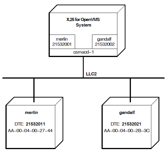
An X.29 application called X29Demo is to be set up for incoming X.25 calls from
the network. Security must be configured to allow these X.25 calls to be verified.
Filters and templates need to be created to allow user-written X.25 applications on the
X.25 for OpenVMS system to make calls to, and receive calls from, remote hosts
on this network.
Details of the entries that must be made in each configuration program section to create the required configuration are provided in the following subsections.
LLC2 DTEs Section
csmacd-1 for each remote X.25 host.- For
merlin, an LLC2 DTE having the following values must be created:- LLC2 DTE Name:
merlin.- Since LLC2 DTEs only reference one remote host, it is useful to give the DTE the same name as the remote host.
DTE Address:
21532001.Outgoing List:
{[1..1024]}Incoming List:{[1..1024]}- The values of the Outgoing List and Incoming List
are set to values appropriate to the remote host. All
local Outgoing Logical Channels for this DTE must
correspond to an Incoming Channel on the remote host's
DTE. Similarly, there must be a local Incoming Logical
Channel for every Outgoing Logical Channel on the remote
host's DTE. In this example, the remote host
merlinhas its DTE's Outgoing List and Incoming List both set to{[1..1024]}(not shown in Figure C.2, ''Example Configuration: X.25 Over LLC2''). Therefore, the Outgoing List and Incoming List for this LLC2 DTE must also be set to{[1..1024]}.
- The values of the Outgoing List and Incoming List
are set to values appropriate to the remote host. All
local Outgoing Logical Channels for this DTE must
correspond to an Incoming Channel on the remote host's
DTE. Similarly, there must be a local Incoming Logical
Channel for every Outgoing Logical Channel on the remote
host's DTE. In this example, the remote host
Remote MAC Address:
AA-00-04-00-27-44- Interface Type:
Negotiated- For LLC2 communication, one DTE must be in DTE mode,
and the other in DCE mode. In this example, the DTE mode
of the remote host
merlin's DTE is unknown. By setting the DTE mode toNegotiated, the two DTEs will negotiate their interface types when enabled.
- For LLC2 communication, one DTE must be in DTE mode,
and the other in DCE mode. In this example, the DTE mode
of the remote host
- DTE Class:
X25_LAN1- Specifying the same DTE class for all LLC2 DTEs on
the same network,enables a single filter to match
incoming calls from allremote hosts on that network. Note that a
DTE class with the name
merlinand having this DTE as its only member, will also be created.
- Specifying the same DTE class for all LLC2 DTEs on
the same network,enables a single filter to match
incoming calls from allremote hosts on that network. Note that a
DTE class with the name
Other values: Default values.
- For
gandalf, an LLC2 DTE having the following values must be created:LLC2 DTE Name:
gandalfDTE Address:
21532002Outgoing List:
{[65..128]}Incoming List:{[1..64]}- In this example, the host
gandalfhas its DTE's Outgoing List set to{[1..64]}, and its Incoming Listset to{[65..128]}(not shown in Figure C.2, ''Example Configuration: X.25 Over LLC2'').Therefore, for this host's LLC2 DTE, the Outgoing List is set to{[65..128]}, and Incoming List is set to{[1..64]}.
- In this example, the host
Remote MAC Address:
AA-00-04-00-2B-3C- Interface Type:
DCE- In this example,
gandalf's DTE is known to be in DTE mode.
- In this example,
- DTE Class:
X25_LAN1, as for LLC2 DTEmerlin.- Note that a DTE class with the name
gandalfand having this DTE as its only member, will also be created.
- Note that a DTE class with the name
Other values: Default values.
The NCL commands corresponding to this section appear in the NCL script under the heading
Create and setup LLC2 DTEs.
Applications Section
Note
The X.29 application values are largely arbitrary as they are dependent on the application being run, but the values specifying the network to send X.25 calls to, and receive X.25 calls from, are significant.
Note also that an application filter must be specified for each remote X.25/LLC2 host.
X29Demo must be specified in the Applications
Section:Application Name:
X29Demo- Application Type:
X.29- This specifies that the application does not write to the X.25
programming interface, but to
stdoutandstdin. However, the application is to be executed in response to an incoming X.29 call.
- This specifies that the application does not write to the X.25
programming interface, but to
- Command File:
SYS$SYSTEM:X29DEMO.COM.- The command file for this application.
- User Name:
oxley- The user ID of the application when handling X.25 calls. This determines the permissions the application possesses while being run.
- Application Template:
Default- This application does not require specific X.25 call settings, so it will accept those specified by the incoming X.25 call.
- Application filter for matching calls from the LAN-based X.25 network:
Filter Name:
x29demo_x25lan1Call Data Mask:
%xffffffffCall Data Value:%x01abacab.- The Call Data is used to select the application to
be run. The first two bytes should be
01, as this indicates an X.29 call. The remainder of the Call Data specifies the X.29 application to run.abacabin this example, selectsX29Demo. Note that if the remainder of the Call Data were empty, this would specify an X.29 login session is to be invoked rather than specifying an X.29 application to be run.
- The Call Data is used to select the application to
be run. The first two bytes should be
- Inbound DTE Class:
X25_LAN1.- This specifies that only incoming calls from the X.25/LLC2 network will be matched by this filter.
Other values: Default values for X.25 filters.
The NCL commands corresponding to the values entered in this configuration section for the
application X29Demoappear in the NCL Script under the heading Create
and set Application Entities. The NCL commands for the application's filter
x29demo_x25lan1 appear under the heading Create and set up X25
Access Filters.
Filters Section
gandalf and merlin.- For remote host
merlin, an X.25 filter with the following values must be specified:Filter Name:
user_merlinCall Data Mask:
%xffffffCall Data Value:%xfacade.- This is to prevent this filter matching X.25 calls
from other applications. Calls made from
merlinthat are to be received by user applications on this node must include the call data value%xfacade.
- This is to prevent this filter matching X.25 calls
from other applications. Calls made from
- Inbound DTE Class:
merlin.- The DTE class
merlinwas created automatically when the DTE was created. Setting the Inbound DTE Class tomerlinspecifies that only incoming calls from hostmerlinwill be matched by this filter. Note that to use this filter to match incoming calls from all remote hosts on the network, the Inbound DTE Class would need to be set toX25_LAN1.
- The DTE class
Other values: Default values for X.25 filters.
- For remote host
gandalf, an X.25 filter with the following values must be specified:Filter Name:
user_gandalfCall Data Mask:
%xffffffCall Data Value:
%xfacade- Inbound DTE Class:
gandalf.- The DTE class
gandalfwas created automatically when the DTE was created.
- The DTE class
Other values: Default values for X.25 filters.
Templates Section
merlin and gandalf.- For outgoing X.25 calls to
merlin, a template having the following values must be specified:Template Name:
user_merlin- Call Data:
%xfacade- This setting assumes that the remote host
merlinis filtering incoming calls based on this call data value.
- This setting assumes that the remote host
- DTE Class:
merlin- This setting ensures that the call is made over the
DTE
merlin, which in turn will ensure it is sent to the remote nodemerlin.
- This setting ensures that the call is made over the
DTE
Other values: Default values.
- For outgoing X.25 calls to
gandalf, a template having the following values must be specified:Template Name:
user_gandalf- Call Data:
%xfacade- Refer to template for
merlinabove.
- Refer to template for
- DTE Class:
gandalf- This setting ensures that the call is made over the
DTE
gandalf, which will ensure it is sent to the remote nodegandalf.
- This setting ensures that the call is made over the
DTE
Other values: Default values.
Incoming Security for Applications
Incoming security for the X.29 application must be specified in the Incoming Security: Applications section. For this example, the following levels of security will be set up:
X29Demo:Remote X.25 hosts
merlinandgandalfwill have unrestricted access to X29Demo.All other nodes will have remote charge access to X29Demo.
X29Demo:*is added to the list of Remote Address Prefixes having an access level of Remote Charge.21532011and21532021are added to the list of Remote Address Prefixes having an access level of All.The list of Remote Address Prefixes having an access level of None is left empty.
The NCL commands corresponding to this security setup lie chiefly under the NCL Script
headings Create Security Filters and Create Remote DTEs.
Remote DTEs are created for each remote X.25 host specified, and rights identifiers are
attributed to them according to the level of access granted that remote host by
different X.25 applications.
Therefore, in the example NCL script, the remote DTE remdte-0 has remote address
prefix set to 21532011, and has a rights identifier of
APPL_X29Demo_ALL. This indicates that the remote host
21532011 has All (unrestricted) access when calling the X.29
application X29Demo.
Incoming Security for Filters
Incoming Security for the two X.25 filters user_merlin and
user_gandalf must be specified to allow calls to be received by
user–written applications using these filters. In this example, the following
levels of access are to be set up in the Incoming Security: Filters section:
user_merlin:Allow all access from remote node
merlin.Allow no access from any other node. Any attempt to allow access from any other node would fail, as the filter
user_merlinwill only match calls that originate frommerlin.
user_gandalf:Allow all access from remote node
gandalf.Allow no access from any other node. Any attempt to allow access from any other node would fail, as the
user_gandalfwill only match calls that originate fromgandalf.
- For the filter
user_merlin,The list of Remote Address Prefixes having an access level of Remote Charge is left empty.
21532011is added to the list of Remote Address Prefixes having an access level of All.*is added to the list of Remote Address Prefixes having an access level of None.
- For the filter
user_gandalf,The list of Remote Address Prefixes having an access level of Remote Charge is left empty.
21532021is added to the list of Remote Address Prefixes having an access level of All.*is added to the list of Remote Address Prefixes having an access level of None.
The NCL commands corresponding to this security setup lie chiefly under the NCL Script
headings Create Security Filters and Create Remote DTEs.Remote
DTEs are created for each remote X.25 host specified, and rights identifiers are
attributed to them according to the level of access granted that remote host by
different X.25 applications.
Therefore, in the example NCL script, the remote DTE remdte-0 has its remote
address prefix set to 21532011, and has a rights identifier of
FILT_user_merlin_ALL. This indicates that the remote host
21532011 has All (unrestricted) access when calling a
user–written application listening on filter user_merlin.
Outgoing Security Section
Processes with the rights identifier
managerswill have all access to all remote addresses.Processes with the rights identifier
staffwill have all access to nodes21532011and21532021, and Remote Charge access to all other nodes.Processes with the rights identifier
userswill have Remote Charge access to21532011and21532021, and no access to other nodes.
- For processes with the rights identifier
managers:The list of Remote Address Prefixes having an access level of Remote Charge is left empty.
*,21532011and21532021are added to the list of Remote Address prefixes having an access level of All. The last two addresses must be specified, as they were given explicit incoming security in the previous section.The list of Remote Address Prefixes having an access level of None is left empty.
- For processes with the rights identifier
staff:*is added to the Remote Address Prefixes having an access level of Remote Charge.21532011and21532021are added to the list of Remote Address Prefixes having an access level of All.The list of Remote Address Prefixes having an access level of None is left empty.
- For processes with the rights identifier
users:21532011and21532021are added to the list of Remote Address Prefixes having an access level of Remote Charge.The list of Remote Address Prefixes having an access level of All is left empty.
*is added to the Remote Address Prefixes having an access level of None.
The NCL commands corresponding to this security setup lie under the NCL Script heading
Create Remote DTEs.Remote DTEs are created for each remote X.25 host
specified, and Access Control entries, which associate the level of access granted with
each group, are placed in the ACL of the Remote DTE.
Therefore, in the example NCL script, the remote DTE remdte-0 has its remote
address prefix set to 21532011, and has an ACL entry with an identifier of
managersand an access level of All. This indicates that
processes with the identifier managers have unrestricted access when making
a call to destination address 21532011.
These values are sufficient to allow an X.29 application and user-written programs to operate over the configuration shown in Figure C.2, ''Example Configuration: X.25 Over LLC2''.
NCL Script for Example B
!
!
!      X25 CONFIGURATION SCRIPT
!   ================================
!
! This script was produced on: Thu Feb 7 15:19:31 2005
!
!
!
!
!
! Create the x25 access entity
!
!
create node 0 x25 access
!
!
! Create the Default Security DTE Class Entity
!
!
create node 0 x25 access security dte class Default
!
!
! Create the x25 protocol entity
!
!
create node 0 x25 protocol
!
!
! Create and setup LLC2 SAP
!
!
create node 0 llc2
create node 0 llc2 sap sap-0
set node 0 llc2 sap sap-0 lan station csma-cd station csmacd-1
set node 0 llc2 sap sap-0 local lsap address 7e
!
!
! Create and setup LLC2 SAP link
!
!
create node 0 llc2 sap sap-0 link merlin
set node 0 llc2 sap sap-0 link merlin -
    remote mac address aa-00-04-00-27-44
set node 0 llc2 sap sap-0 link merlin remote lsap address 7e
!
! Create and setup llc2 dtes
!
create node 0 x25 protocol dte merlin profile "ISO8881"
set node 0 x25 protocol dte merlin inbound dte class X25_LAN1
set node 0 x25 protocol dte merlin x25 address 21532001
set node 0 x25 protocol dte merlin -
    link service provider llc2 sap sap-0 link merlin
set node 0 x25 protocol dte merlin outgoing list {[1..1024]}
set node 0 x25 protocol dte merlin incoming list {[1..1024]}
set node 0 x25 protocol dte merlin -
    extended packet sequencing false, maximum window size 7 -
    , minimum window size 1 , default window size 2
set node 0 x25 protocol dte merlin default packet size 128
set node 0 x25 protocol dte merlin interface type negotiated
create node 0 llc2 sap sap-0 link gandalf
set node 0 llc2 sap sap-0 link gandalf -
    remote mac address aa-00-04-00-2b-3c
set node 0 llc2 sap sap-0 link gandalf remote lsap address 7e
create node 0 x25 protocol dte gandalf profile "ISO8881"
set node 0 x25 protocol dte gandalf inbound dte class X25_LAN1
set node 0 x25 protocol dte gandalf x25 address 21532002
set node 0 x25 protocol dte gandalf -
    link service provider llc2 sap sap-0 link gandalf
set node 0 x25 protocol dte gandalf outgoing list {[65..128]}
set node 0 x25 protocol dte gandalf incoming list {[1..64]}
set node 0 x25 protocol dte gandalf -
    extended packet sequencing false, maximum window size 7 -
    , minimum window size 1 , default window size 2
set node 0 x25 protocol dte gandalf default packet size 128
set node 0 x25 protocol dte gandalf interface type dce
!
! Create Local DTE Class: merlin
!
create x25 access dte class merlin type local
set x25 access dte class merlin security dte class Default
set x25 access dte class merlin local dtes (merlin)
!
! Create Local DTE Class: X25_LAN1
!
create x25 access dte class X25_LAN1 type local
set x25 access dte class X25_LAN1 security dte class Default
set x25 access dte class X25_LAN1 local dtes (gandalf,merlin)
!
! Create Local DTE Class: gandalf
!
create x25 access dte class gandalf type local
set x25 access dte class gandalf security dte class Default
set x25 access dte class gandalf local dtes (gandalf)
!
!
! Create and set reachable addresses
!
!
create node 0 x25 access reachable address x121 address prefix 37
set node 0 x25 access reachable address x121 mapping X.121
set node 0 x25 access reachable address x121 address extensions true
create node 0 x25 access reachable address x121d address prefix 36
set node 0 x25 access reachable address x121d mapping X.121
set node 0 x25 access reachable address x121d address extensions true
!
!
! Create and set up X25 Access FILTERS
!
!
create node 0 x25 access filter "OSI Transport"
set node 0 x25 access filter "OSI Transport" -
    call data value ’03010100’H , call data mask ’FFFFFFFF’H
set node 0 x25 access filter "OSI Transport" -
    redirect reason not specified
set node 0 x25 access filter "OSI Transport" security filter Default
create node 0 x25 access filter x29demo_x25lan1
set node 0 x25 access filter x29demo_x25lan1 priority 1
set node 0 x25 access filter x29demo_x25lan1 call data value %x01abacab -
    , call data mask %xffffffff
set node 0 x25 access filter x29demo_x25lan1 inbound dte class X25_LAN1
set node 0 x25 access filter x29demo_x25lan1 -
    security filter APPL_X29Demo
create node 0 x25 access filter user_merlin
set node 0 x25 access filter user_merlin priority 1
set node 0 x25 access filter user_merlin call data value %xfacade -
    , call data mask %xffffff
set node 0 x25 access filter user_merlin inbound dte class merlin
set node 0 x25 access filter user_merlin -
security filter FILT_user_merlin
create node 0 x25 access filter user_gandalf
set node 0 x25 access filter user_gandalf priority 1
set node 0 x25 access filter user_gandalf call data value %xfacade -
    , call data mask %xffffff
set node 0 x25 access filter user_gandalf inbound dte class gandalf
set node 0 x25 access filter user_gandalf -
    security filter FILT_user_gandalf
!
!
! Create and set application entities
!
!
create node 0 x25 access application X29Demo
set node 0 x25 access application X29Demo type x29
set node 0 x25 access application X29Demo filters (x29demo_x25lan1)
set node 0 x25 access application X29Demo file "SYS$SYSTEM:X29DEMO.COM"
set node 0 x25 access application X29Demo template Default
set node 0 x25 access application X29Demo user "oxley"
!
!
! Create and set templates
!
!
create node 0 x25 access template Default
set node 0 x25 access template Default throughput class request [0..0]
set node 0 x25 access template Default reverse charging false
set node 0 x25 access template Default fast select not specified
set node 0 x25 access template Default charging information false
set node 0 x25 access template Default transit delay selection 0
set node 0 x25 access template Default end-to-end delay [0..0]
set node 0 x25 access template Default expedited data not specified
set node 0 x25 access template Default nsap mapping false
create node 0 x25 access template "OSI Transport"
set node 0 x25 access template "OSI Transport" call data ’03010100’H
set node 0 x25 access template "OSI Transport" packet size 2048
set node 0 x25 access template "OSI Transport" reverse charging false
set node 0 x25 access template "OSI Transport" fast select not specified
set node 0 x25 access template "OSI Transport" -
    charging information false
set node 0 x25 access template "OSI Transport" -
    transit delay selection 0
set node 0 x25 access template "OSI Transport" end-to-end delay [0..0]
set node 0 x25 access template "OSI Transport" -
    expedited data not specified
set node 0 x25 access template "OSI Transport" nsap mapping true
create node 0 x25 access template user_merlin
set node 0 x25 access template user_merlin dte class merlin
set node 0 x25 access template user_merlin call data %xfacade
set node 0 x25 access template user_merlin -
    throughput class request [0..0]
set node 0 x25 access template user_merlin reverse charging false
set node 0 x25 access template user_merlin fast select not specified
set node 0 x25 access template user_merlin charging information false
set node 0 x25 access template user_merlin transit delay selection 0
set node 0 x25 access template user_merlin end-to-end delay [0..0]
set node 0 x25 access template user_merlin expedited data not specified
set node 0 x25 access template user_merlin nsap mapping false
create node 0 x25 access template user_gandalf
set node 0 x25 access template user_gandalf dte class gandalf
set node 0 x25 access template user_gandalf call data %xfacade
set node 0 x25 access template user_gandalf -
    throughput class request [0..0]
set node 0 x25 access template user_gandalf reverse charging false
set node 0 x25 access template user_gandalf fast select not specified
set node 0 x25 access template user_gandalf charging information false
set node 0 x25 access template user_gandalf transit delay selection 0
set node 0 x25 access template user_gandalf end-to-end delay [0..0]
set node 0 x25 access template user_gandalf expedited data not specified
set node 0 x25 access template user_gandalf nsap mapping false
!
!
! Create Security filters
!
!
create x25 access security filter Default
set x25 access security filter Default acl ((identifier =( Default_ALL -
    ), access = ALL),(identifier = ( Default_REMOTE -
    ), access = REMOTE_CHARGE),(identifier = ( Default_NONE -
    ), access = NONE))
create x25 access security filter APPL_X29Demo
set x25 access security filter APPL_X29Demo -
    acl ((identifier =( APPL_X29Demo_ALL -
    ), access = ALL),(identifier = ( APPL_X29Demo_REMOTE -
    ), access = REMOTE_CHARGE),(identifier = ( APPL_X29Demo_NONE -
    ), access = NONE))
create x25 access security filter FILT_user_merlin
set x25 access security filter FILT_user_merlin -
    acl ((identifier =( FILT_user_merlin_ALL -
    ), access = ALL),(identifier = ( FILT_user_merlin_REMOTE -
    ), access = REMOTE_CHARGE),(identifier = ( FILT_user_merlin_NONE -
    ), access = NONE))
create x25 access security filter FILT_user_gandalf
set x25 access security filter FILT_user_gandalf -
    acl ((identifier =( FILT_user_gandalf_ALL -
    ), access = ALL),(identifier = ( FILT_user_gandalf_REMOTE -
    ), access = REMOTE_CHARGE),(identifier = ( FILT_user_gandalf_NONE -
    ), access = NONE))
!
!
! Create Remote DTEs
!
!
create x25 access security dte class Default remote dte match_all -
    remote address prefix *
set x25 access security dte class Default remote dte match_all -
    rights identifiers (FILT_user_gandalf_NONE,FILT_user_merlin_NONE, -
    APPL_X29Demo_REMOTE)
set x25 access security dte class Default remote dte match_all -
    acl ( ( identifier = { managers }, access = ALL), ( identifier = { staff -
    }, access = REMOTE_CHARGE), ( identifier = { users }, access = NONE))
create x25 access security dte class Default remote dte remdte-0 -
    remote address prefix 21532011
set x25 access security dte class Default remote dte remdte-0 -
    rights identifiers (FILT_user_merlin_ALL,APPL_X29Demo_ALL)
set x25 access security dte class Default remote dte remdte-0 -
    acl ( ( identifier = { staff }, access = ALL), ( identifier = { managers -
    }, access = ALL), ( identifier = { users }, access = REMOTE_CHARGE))
create x25 access security dte class Default remote dte remdte-1 -
    remote address prefix 21532021
set x25 access security dte class Default remote dte remdte-1 -
    rights identifiers (FILT_user_gandalf_ALL,APPL_X29Demo_ALL)
set x25 access security dte class Default remote dte remdte-1 -
    acl ( ( identifier = { staff }, access = ALL), ( identifier = { managers -
    }, access = ALL), ( identifier = { users }, access = REMOTE_CHARGE))
!
!
! Include the user’s extra enable ncl script
!
!
do sys$startup:x25_extra_security.ncl
!
!
! Include the user’s extra create ncl script
!
!
do sys$startup:x25_extra_create.ncl
!
!
! Include the user’s extra set ncl script
!
!
do sys$startup:x25_extra_set.ncl
!
! Enable the LLC2 SAPs
!
enable node 0 llc2 sap sap-0
!
! Enable the LLC2 SAP links and DTEs
!
enable node 0 llc2 sap sap-0 link merlin
enable x25 protocol dte merlin
enable node 0 llc2 sap sap-0 link gandalf
enable x25 protocol dte gandalf
!
!
! Enable x25 access
!
!
enable node 0 x25 access
!
!
! Enable application entities
!
!
enable node 0 x25 access application X29Demo
!
!
! Include the user’s extra enable ncl script
!
!
do sys$startup:x25_extra_enable.ncl
Appendix D. Characteristic Values of the Default and OSI Transport Templates
Default and
OSI Transport templates.|
Characteristic |
Value in Default Template |
Value in OSI Transport Template |
|---|---|---|
|
DTE class |
– |
– |
|
Call data |
– |
%x03010100 |
|
Packet size |
– |
2048 |
|
Window size |
– |
– |
|
Destination X.25 address |
– |
– |
|
Fast select option |
– |
– |
|
Reverse charging |
False |
False |
|
Selected group |
– |
– |
|
Throughput class request |
– |
– |
|
Charging information |
False |
False |
|
RPOA sequence |
– |
– |
|
Local subaddress |
– |
– |
|
Target address extension |
– |
– |
|
NSAP mapping |
False |
True |
|
Calling address extension |
– |
– |
|
Transit delay selection |
– |
– |
|
End-to-end delay |
– |
– |
Appendix E. Configuration Files – Location and Use
This Appendix lists the location and use of configuration files that are either created as a
result of running the configuration program in basic and advanced configuration modes or
referenced when the system is booted. Table E.1, ''Configuration Files Common to Both Basic and Advanced Modes'' lists the location
and use of files common to both basic and advanced modes. These include user NCL scripts,
which contain user–supplied NCL commands that are used to augment the commands in the
master NCL script. These scripts are called by X25$CONFIG.NCL whenever the
system is booted.
SYS$STARTUP:X25$CONFIG.NCL | |
|
The master NCL script that contains the NCL commands to create the X.25 configuration. This file is generated by running the configuration program in either BASIC or ADVANCED mode and should not be edited. If the configuration needs to be changed, either run
| |
SYS$STARTUP:X25$ENABLE_DECNET_CLIENTS.NCL | |
|
On OpenVMS VAX systems, this NCL script contains the NCL commands
to enable the | |
SYS$STARTUP:X25$EXTRA_CREATE.NCL | |
|
File containing additional, user–supplied NCL commands specific to creating entities. By default, this file does not contain any NCL commands. | |
SYS$STARTUP:X25$EXTRA_ENABLE.NCL | |
|
File containing additional, user–supplied NCL commands specific to enabling entities. By default, this file does not contain any NCL commands. | |
SYS$STARTUP:X25$EXTRA_SECURITY.NCL | |
|
File containing additional, user–supplied NCL commands specific to security. By default, this file does not contain any NCL commands. | |
SYS$STARTUP:X25$EXTRA_SET.NCL | |
|
File containing additional, user–supplied NCL commands specific to setting the values of entities. By default, this file does not contain any NCL commands. | |
SYS$STARTUP:X25$BASIC_CONFIG.DAT | |
|
File in which the X.25 configuration created by running the configuration program in BASIC mode is saved. This file is created so that it is available for reloading if the option to modify the configuration is selected when running the configuration program in either BASIC or ADVANCED modes. Refer to Note below. | |
SYS$STARTUP:X25$CONFIG.DAT | |
|
File in which the X.25 configuration created by running the configuration program in ADVANCED mode is saved. This file is created so that it is available for reloading if the option to modify the configuration is selected only when running the configuration program in ADVANCED mode. Refer to Note below. | |
Note
If both X25$CONFIG.DAT and X25$BASIC_CONFIG.DAT have been created
and the "Modify an existing configuration script" option is selected
when running the configuration program in ADVANCED mode, then
X25$CONFIG.DAT will be used.
X25$CONFIG.DAT is the only file created and the "Modify an existing
configuration script" option is selected when running the configuration
program in BASIC mode, X25$CONFIG.DAT will not be used. You can do one
of the following:Exit BASIC mode and reinvoke the configuration program in ADVANCED mode.
Choose the "Create a new configuration script" option from the Main Menu.
Multiple DTEs are permitted only for LAN configurations.
The value entered must lie outside the incoming and outgoing channel ranges for the specified DTE.
You must set up at least one synchronous line and associated DTE or at least one LLC2 or XOT DTE.
DECnet-Plus must be installed and configured in order to complete this section.
This is the name of an OSI TRANSPORT TEMPLATE entity. This is not used for the NSP transport. If you specify a value other than Default, you must configure the corresponding OSI TRANSPORT TEMPLATE entity using the DECnet–Plus configuration program.
Subject to PSDN restrictions
You only need to make this choice if the Profile you have entered supports the facility.
You only need to enter values here if you have chosen to use Packet Level Negotiation.
You need to supply these values only if you have chosen to use Packet Level Negotiation. If Packet Level Negotiation is not selected,you are prompted for the Packet Size and the Level 3 Window Size.
You need to supply these values only if you have chosen to use Packet Level Negotiation. If Packet Level Negotiation is not selected,you are prompted for the Packet Size and the Level 3 Window Size.
The value entered must lie outside the incoming and outgoing channel ranges specified for the DTE
Subject to PSDN restrictions
Subject to PSDN restrictions
You need to supply this information only if the Group type is a BCUG.
If a template that has not yet been defined is entered, information about the template is requested. Details of the information required to define a template are given in Table 7.12, ''Configuration Information: Templates ''. This prompt is only displayed for X.29 applications.
If a filter that has not yet been defined is entered, information about the filter is requested. Details of the information required to define a filter are given in Table 7.11, ''Configuration Information: Filters''.
If a filter that has not yet been defined is entered, information about the filter is requested. Details of the information required to define a filter are given in Table 7.11, ''Configuration Information: Filters''.
You need to supply this value only if you have selected Manual as the conversion mechanism.
If a filter that has not yet been defined is entered, information about the filter is requested. Details of the information required to define a filter are given in Table 7.11, ''Configuration Information: Filters''.
The Remote Address Prefix (RAP) is used to match against the remote DTE address in incoming and outgoing calls.
The wildcard character (*) means all unspecified DTEs. Even if you enter specific DTEs that are to have No Access, by default all other unspecified DTEs will also have No Access. However, if you enter the wildcard character to stand for DTEs that have Remote Charge or All Access, there will be no default for this value, and the only DTEs that will not be allowed access are those that you specify explicitly.
The Remote Address Prefix (RAP) is used to match against the remote DTE address in incoming and outgoing calls.
The wildcard character (*) means all unspecified DTEs. Even if you enter specific DTEs that are to have no access, by default all other unspecified DTEs will also have no access. However, if you enter the wildcard character to stand for DTEs that have Remote Charge or all access, there will be no default for this value, and the only DTEs that will not be allowed access are those that you specify explicitly.
The Remote Address Prefix (RAP) is used to match against the remote DTE address in incoming and outgoing calls.
The wildcard character (*) means all unspecified DTEs. Even if you enter specific DTEs that are to have no access,by default all other unspecified DTEs will also have no access. However, if you enter the wildcard character to stand for DTEs that have Remote Charge or all access, there will be no default for this value, and the only DTEs that will not be allowed access are those that you specify explicitly.
Specify the group to which the local process belongs.
The Remote Address Prefix (RAP) is used to match against the remote DTE address in incoming and outgoing calls.
You will be asked for this information only if you have configured PVCs.
The wildcard character (*) means all unspecified DTEs. Even if you enter specific DTEs that are to have No Access, by default all other unspecified DTEs will also have No Access. However, if you enter the wildcard character to stand for DTEs that have Remote Charge or All access, there will be no default for this value, and the only DTEs that will not be allowed access are those that you specify explicitly.
Multiple LAN remote hosts are permitted.
Multiple DTEs are permitted only for LAN configurations.