VSI X.25 for OpenVMS Problem Solving Guide
- Software Version:
- VSI X.25 for OpenVMS Version 2.1
- Operating System and Version:
- VSI OpenVMS IA-64 Version 8.4-1H1 or higher
VSI OpenVMS Alpha Version 8.4-2L1 or higher
Preface
This manual describes some of the problems that may occur when using the VSI X.25 for OpenVMS software, and how to solve them.
The information in this manual applies to the X.25 functionality provided by VSI X.25 for OpenVMS and VSI DECnet-Plus for OpenVMS VAX. Note that the X.25 functionality in VSI DECnet-Plus for OpenVMS VAX was formerly provided by VAX P.S.I. software.
Throughout this manual, the X.25 functionality provided by both VSI X.25 for OpenVMS and VSI DECnet-Plus for OpenVMS VAX is referred to generically as X.25 for OpenVMS.
This manual uses the term Packet Switching Data Network (PSDN) to refer to any public or private packet switching network that X.25 for OpenVMS supports.
1. About VSI
VMS Software, Inc. (VSI) is an independent software company licensed by Hewlett Packard Enterprise to develop and support the OpenVMS operating system.
2. Intended Audience
Local Area Networks (LANs)
Wide Area Networks (WANs)
Installation of software products on OpenVMS
X.25 Communications
VSI X.25 for OpenVMS
3. Document Structure
Chapter 1, describes the preparation needed for problem solving.
Chapter 2, describes how to analyze and correct X.25–related problems.
Chapter 3, describes how to analyze and correct X.29–related problems.
Appendix A, describes how to test the communications link between an X.25 for OpenVMS system and the PSDN.
Appendix B, lists the X.25 cause codes used in X.25 for OpenVMS.
Appendix C, lists the X.25 diagnostic codes used in X.25 for OpenVMS.
4. Related Documents
The following sections describe VSI DECnet-Plus for OpenVMS, VSI X.25 for OpenVMS, and VSI OpenVMS manuals that either directly describe the X.25 for OpenVMS software or provide related information.
VSI DECnet-Plus for OpenVMS Documentation
VSI DECnet-Plus for OpenVMS Introduction and User's Guide
This manual provides general information on DECnet-Plus and describes the concept of packet switching data networks.
VSI DECnet-Plus for OpenVMS Installation and Configuration
This manual describes how to install and configure VSI DECnet-Plus for OpenVMS software. For OpenVMS I64 and OpenVMS Alpha systems, this manual also describes how to install X.25 for OpenVMS software. Details on configuring X.25 for OpenVMS on OpenVMS I64 and OpenVMS Alpha systems are provided in the VSI X.25 for OpenVMS Configuration manual. For OpenVMS VAX systems, this manual also describes how to install and configure the X.25 functionality provided by VSI DECnet-Plus for OpenVMS VAX.
VSI DECnet-Plus for OpenVMS Network Management Guide
This manual provides conceptual and task information about managing and monitoring a DECnet-Plus network. In addition, the manual devotes a section to the management of X.25 entities used by DECnet operating over X.25 data links.
VSI DECnet-Plus for OpenVMS Network Control Language Reference Guide
This manual provides detailed information on the Network Control Language (NCL), which is used to manage X.25 for OpenVMS management entities.
VSI X.25 for OpenVMS Documentation
VSI X.25 for OpenVMS Configuration (OpenVMS I64 and OpenVMS Alpha)
This manual explains how to configure X.25 for OpenVMS software on OpenVMS I64 and OpenVMS Alpha systems.
VSI X.25 for OpenVMS Security Guide
This manual describes the X.25 Security model and how to set up, manage, and monitor X.25 Security to protect your X.25 for OpenVMS system from unauthorized incoming and outgoing calls.
VSI X.25 for OpenVMS Problem Solving
This manual provides guidance on how to analyze and correct X.25–related and X.29–related problems that may occur while using the X.25 for OpenVMS software. In addition, the manual describes loopback testing for LAPB data links.
X.25 for OpenVMS Programming
This manual describes how to write X.25 and X.29 programs to perform network operations.
X.25 for OpenVMS Programming Reference
This manual provides reference information for X.25 and X.29 programmers. It is a companion manual to the X.25 for OpenVMS Programming.
X.25 for OpenVMS Utilities
This manual describes how to use and manage X.25 Mail and how to use and manage a host–based PAD to connect to a remote system. It also describes how to manage the X.29 communication links used for both of these functions. In addition, this manual explains how to use OpenVMS DCL SET TERMINAL/X29 commands to manage remote host–based or network PADs.
X.25 for OpenVMS Accounting
This manual describes how to use X.25 Accounting to obtain performance records and information on how X.25 is being used on your system.
VSI OpenVMS Documentation
VSI OpenVMS DCL Dictionary
VSI OpenVMS System Management Utilities Reference Manual
VSI OpenVMS System Services Reference Manual
VSI OpenVMS Guide to System Security
5. OpenVMS Documentation
The full VSI OpenVMS documentation set can be found on the VMS Software Documentation webpage at https://docs.vmssoftware.com.
6. VSI Encourages Your Comments
You may send comments or suggestions regarding this manual or any VSI document by sending electronic mail to the following Internet address: <docinfo@vmssoftware.com>. Users who have VSI OpenVMS support contracts through VSI can contact <support@vmssoftware.com> for help with this product.
7. Terminology
|
VAX P.S.I. |
X.25 for OpenVMS |
|---|---|
|
VAX P.S.I. |
X.25 for OpenVMS VAX |
|
Access system |
X.25 Client system |
|
Native system |
X.25 Direct Connect system |
|
Multihost system |
X.25 Connector system |
|
Gateway system |
X.25 Connector system |
|
Client system |
A client system of an X.25 Connector system (and therefore a client of the X25 Server management module on the X.25 Connector system.) |
|
Relay Client system |
A client system of an X.25 Relay system (and therefore a client of the X25 Relay management module on the X.25 Relay system.) |
|
Relay–Client |
A shorthand term for an X25 RELAY CLIENT management entity on an X.25 Relay system that contains management information about an actual Relay Client system. |
|
Relay system |
An X.25 Direct Connect or Connector system with the X.25 Relay module enabled. |
|
Server Client system |
Another term for a Client system. |
|
Server–Client |
A shorthand term for an X25 SERVER CLIENT management entity on an X.25 Connector system that contains management information about one or more actual X.25 Client systems. |
For more information about clients, servers, and relays in X.25 for OpenVMS, refer to the VSI X.25 for OpenVMS Configuration manual and the VSI X.25 for OpenVMS Management Guide.
8. Conventions
| Convention | Meaning |
|---|---|
|
UPPERCASE and lowercase |
The OpenVMS operating system does not differentiate between lowercase and uppercase characters. Literal strings that appear in text, examples, syntax descriptions, and function descriptions can be entered using uppercase characters, lowercase characters, or a combination of both. In running text, uppercase characters indicate OpenVMS DCL commands and command qualifiers; Network Control Language (NCL) commands and command parameters; other product–specific commands and command parameters; network management entities; OpenVMS system logical names; and OpenVMS system service calls, parameters, and item codes. Leading uppercase characters, such as Protocol State, indicate management entity characteristics and management entity event names. Leading uppercase characters are also used for the top-level management entities known as modules. |
|
|
This typeface is used in interactive and code examples to indicate system output. In running text, this typeface is used to indicate the exact name of a device, directory, or file; the name of an instance of a network management entity; or an example value assigned to a DCL qualifier or NCL command parameter. |
|
|
In interactive examples, user input is shown in
|
|
$ |
In this manual, a dollar sign ($) is used to represent the default OpenVMS user prompt. |
|
CTRL |
In procedures, a sequence such as
CTRL |
|
italic text |
Italic text indicates variables or book names. Variables include information that varies in system input and output. In discussions of event messages, italic text indicates a possible value of an event argument. |
|
bold text |
Bold text indicates an important term, or important information. |
|
( ) |
In a command definition, parenthesis indicate that you must enclose the options in parenthesis if you choose more than one. Separate the options using commas. |
|
{ } |
In a command definition, braces are used to enclose sets of values. The braces are a required part of the command syntax. |
|
[ ] |
In a command definition, square brackets are used to enclose parts of the command that are optional. You can choose one, none, or all of the options. The brackets are not part of the command syntax. However, brackets are a required syntax element when specifying a directory name in an OpenVMS file specification. |
Chapter 1. Preparations for Problem Solving
1.1. Introduction
This manual contains information to help you solve problems that may occur when using VSI X.25 for OpenVMS.
Problems can occur for a number of reasons. The problem solving procedures in Chapter 2 and Chapter 3 help you to determine where the problems are.
This chapter describes the problem solving tools that are used in the procedures, and the information you need to solve X.25 problems.
1.2. Problem Solving Tools
Sections 1.2.1 to 1.2.5 describe the problem solving tools that can be used to help you solve X.25 problems.
1.2.1. NCL
During problem solving, you will need to enter Network Control Language (NCL) commands from a suitable node. Refer to the VSI DECnet-Plus for OpenVMS Network Control Language Reference Guide manual for details on how to start NCL on your node.
NCL commands are issued that override the current settings.
The system is rebooted. As part of this action, the NCL commands in the current configuration file are executed and therefore override any NCL commands previously issued.
The configuration program is run to generate a new configuration file and the system is rebooted.
1.2.2. Event Logging
Event Logging monitors the events generated by the network. Network events inform you of what is happening on the network and where there are any problems. Refer to the VSI DECnet-Plus for OpenVMS Network Management Guide manual for information on how to set up and manage event logging.
Refer to Table 2.1 in Chapter 2 of this manual for more details of the events logged by X.25 for OpenVMS.
1.2.3. Counters
Counters tabulate the number of times an entity has performed a particular operation or the number of times a certain condition or event has occurred since the entity was created. For example, you can determine the number of times an event has been generated by looking at the appropriate counter.
Counter values are dynamically maintained by the system and cannot be reset by the system manager.
For more information about counters, refer to the VSI DECnet-Plus for OpenVMS Network Control Language Reference Guide manual.
1.2.4. Common Trace Facility (CTF)
The Common Trace Facility (CTF) allows you to collect and display information about specific protocol exchanges between systems in a network.
For more information on the trace facility and its components refer to the DECnet/OSI for OpenVMS Common Trace Facility Use manual.
1.2.5. Loopback Tests
Loopback tests can be used to test the access to the physical link between the X.25 for OpenVMS system and the PSDN. Appendix A describes how to perform loopback tests.
1.3. Solving a Problem – General Procedure
The necessary documentation to help you solve problems
Information on the PSDN, including the DTE addresses
Chapter 2 describes how to analyze and correct X.25 problems.
Chapter 3 describes how to analyze and correct X.29 problems.
In the problem solving sections, the left–hand pages ask questions about the problem. When the answer to a question points you to a numbered note, read the specified note which is on the right–hand page. Read the note and perform any actions specified.
If as a result of solving the problem you have had to change one or more X.25 management entities, you should either add the changes to the appropriate user NCL script file (on OpenVMS I64 and OpenVMS Alpha systems) or re–run the configuration program. This action ensures that your network will maintain the same configuration the next time the system is rebooted.
For details on using NCL, refer to the VSI X.25 for OpenVMS Management Guide.
For details on configuring X.25 for OpenVMS on OpenVMS I64 and OpenVMS Alpha systems, refer to the VSI X.25 for OpenVMS Configuration manual.
For details on configuring X.25 for OpenVMS on OpenVMS VAX systems, refer to the VSI DECnet-Plus for OpenVMS Installation and Configuration manual.
If you cannot solve the problem by using the methods suggested in this manual, contact VMS Software, Inc. for information about the variety of service options available to you and the procedures for submitting software problem reports. For details on how to submit an X.25 for OpenVMS problem, see Appendix D.
Chapter 2. X.25 Problems
2.1. Introduction
X.25 for OpenVMS fails to run after system reboot (refer to Section 2.4).
A DTE fails (refer to Section 2.5).
Incoming calls cannot be received on a local DTE (refer to Section 2.6).
Incoming calls cannot be received on Client systems (refer to Section 2.7).
Outgoing calls cannot be made (refer to Section 2.8).
Calls cannot be relayed by an X.25 Relay system (refer to Section 2.9).
A virtual circuit fails, terminating a call (refer to Section 2.10).
User application programs fail (refer to Section 2.11).
Each of the referenced sections describes a procedure that enables you to determine the exact nature of the problem, and recommends the action that should be taken to rectify the problem.
2.2. General Procedure
Log in to a suitably privileged account, for example, log in as
SYSTEM.Enable event logging.
Refer to the VSI DECnet-Plus for OpenVMS Network Management Guide manual for information on how to set up and manage event logging.
Ensure that X.25 for OpenVMS has been started.
Look in the event log for event messages that indicate possible problems and then refer to Section 2.3.
Where relevant, follow the associated reference to the appropriate problem solving section.
Follow the procedure described in the problem solving section to further isolate the cause of the problem, then take whatever action is recommended.
2.3. Event Messages
An indication of which management module produced the event message
A brief description of the event message
The action to take to resolve the problem
Some event messages merely inform you of network conditions that do not represent problems; for example, a DTE becoming available. Such event messages therefore do not refer you to a problem solving section.
|
Event Message |
Generator |
Description/Action |
|---|---|---|
|
X25 SERVER CLIENT |
Description: Occurs when an attempt to establish a DECnet connection to the Client system fails. The Nodes argument displays the full name of the Client system. The Application argument displays the application number in the CLIENT entity. Action: See Section 2.7 for additional problem solving information. | |
|
X25 RELAY CLIENT |
Description: Occurs when an attempt to relay an X.25 call fails. The Failure Reason argument specifies whether the connection failed at the incoming or outgoing stage. Incoming Stage: A Failure
Reason argument of Call Accept Failure
indicates that the call has been forwarded, and accepted by the
called DTE, but the Relay system could not pass the accept back
to the calling DTE. The Call Accept Reason argument indicates
why the call could not be accepted; the argument takes one of
the following values:
Action: Use the Call Accept Reason argument (specified above) to determine why the failure occurred. Outgoing Stage: A Failure Reason of Outgoing Call Failure indicates the Relay system received the call, but could not forward it to the destination DTE. The Outgoing Failure Reason indicates why the call could not be forwarded;the argument takes one of the following values:
Action: Refer to Section 2.9. | |
|
X25 RELAY CLIENT |
Description: Occurs when a
connection that has been successfully established is abnormally
terminated. The Reason argument specifies the reason for the
loss of connection; it takes one of the following values:
| |
|
X25 RELAY PVC |
Description: Occurs when a connection that has been successfully established is abnormally terminated. The Reason argument specifies the reason for the loss of the connection.
Action: Refer to each of the
error reasons below and take the specified action.
| |
|
X25 PROTOCOL DTE |
Description: Occurs when the DTE receives a Diagnostic packet from the network. Action: If the LCN on which the packet is received is non–zero, this event message is an informational message and requires no action. If the LCN is zero, the PSDN is sending notification of a protocol error. In this case, this event is followed by a Switched Virtual Circuit Failed event; refer to Section 2.10. | |
|
X25 PROTOCOL DTE |
Description: Occurs when the
X25PROTOCOL DTE entity's State status attribute changes from
Action: Refer to Section 2.5. | |
|
X25 PROTOCOL DTE |
Description: Occurs when the
X25PROTOCOL DTE entity's State status attribute changes to
Action: This event message is an informational message, and requires no action. | |
|
Description: Occurs when an FRMR (frame reject) frame is received from the remote station. This indicates a link protocol error of some kind, and will cause the DTE to fail, in which case a DTE Down event will be logged. Action: Refer to Section 2.5. | |
|
Description: Occurs when the receipt of a frame causes an FRMR (frame reject) frame to be generated and transmitted to the remote station. This indicates a link protocol error of some kind, and will cause the DTE to fail, in which case a DTE Down event will be logged. Action: Refer to Section 2.5. | |
|
X25 PROTOCOL DTE |
Description:Occurs when the DTE
receives an illegal packet from the network. This indicates some
type of protocol error; the Failure Reason argument explains the
nature of the error.
the DTE will fail, so the DTE Down event will also be logged.
Action: Refer to Section 2.5.
the virtual circuit will fail, so the Switched Virtual Circuit Failed event will also be logged. Action: Refer to Section 2.10. | |
|
X25 ACCESS |
Description: Occurs when an incoming call from the X25 Protocol module (or from the X25 Client module in an accessing system) is blocked by the X25 Access module's security mechanisms. The call is cleared by the X25 Access module. This event may signal an attempted security violation. However, if the calling DTE is one that should actually be permitted to make incoming calls, the event indicates that X.25 security has been set up incorrectly. Action: Refer to the VSI X.25 for OpenVMS Security Guide for more information. | |
|
X25 ACCESS |
Description: Occurs when an incoming call from the X25 Protocol module (or from the X25 Client module in an accessing system) is cleared by the X25 Access module. The reason for the failure is given by the Failure Reason argument.
Action:
| |
|
Description: Occurs when the
status attribute Protocol State of the LAPB LINK or the LLC2 SAP
LINK is Action: Refer to Section 2.5. | |
|
Description:Occurs when the link protocol is attempting to re–initialize. This event is followed by the DTE Down event. Action: Refer to Section 2.5. | |
|
Description:Occurs when the
status attribute Protocol State of the LAPB LINK or LLC2 SAP
LINK is Action: Refer to Section 2.5. | |
|
LAPB LINK |
Description: Occurs when the
status attribute Protocol State of the LAPB LINK is
Action: Refer to Section 2.5. | |
|
Description: Occurs when the protocol is being reset. Action: If the reset causes the DTE to fail, the DTE Down event will also be logged; see Section 2.5. Otherwise, no further action is required. | |
|
Description: Occurs when the
protocol has been successfully initialized and the status
attribute Protocol State is Action: This event message is an informational message and requires no action. | |
|
Description: Occurs when the protocol has failed to initialize correctly after the maximum number of allowed attempts. Action: Refer to Section 2.5. | |
|
Description:Occurs when the
status attribute Protocol State of the LAPB LINK, LLC2 SAP LINK,
or XOT SAP LINK entity changes from
Action: If the state change is
from | |
|
X25 PROTOCOL DTE |
Description:Occurs when the DTE receives a Reset packet from the network. Action: If the DTE fails as a result, the DTE Down event will also be logged; refer to Section 2.5. | |
|
X25 PROTOCOL DTE |
Description:
| |
|
Outbound Connect Failed |
XOT SAP LINK |
Description: Occurs when an
attempt to establish an outbound connection with a remote system
fails. The event returns the following arguments:Failure Reason,
Remote IP Address, Remote Port Number,and, if the Failure Reason
argument indicates PWIP Error, PWIP Error
Code. The Failure Reason argument indicates why the connection
could not be made; the argument takes one of the following
values:
|
|
X25 ACCESS |
Description: Occurs when the X25 Access module's security mechanisms prevent a client from making an outgoing call. This event usually indicates an attempted security violation. However, if the client is one that should actually be permitted to make outgoing calls,the event indicates that X.25 security has been set up incorrectly. Action: Refer to the VSI X.25 for OpenVMS Security Guide for more information. | |
|
X25 ACCESS |
Description: Occurs when a call fails because X.25 security has been set up incorrectly. Action: Refer to Section 2.8. | |
|
X25 ACCESS |
Description: Occurs when the call has been cleared by the network, by one of the DTEs, or by a network management command. Action: This event message is an informational message and requires no action unless the call was cleared unexpectedly. If the call was cleared unexpectedly, refer to Section 2.10. | |
|
Protocol Error |
XOT SAP LINK |
Description: Occurs when an
error occurs in the XOT protocol during a XOT protocol exchange
with the remote system. The event returns the following
arguments:Error Reason, Remote IP Address, Remote Port Number,
and Received PDU. The Error Reason argument indicates what type
of protocol error was detected; the argument takes one of the
following values:
Action: Refer to Section 2.5.4.3. |
|
X25 PROTOCOL DTE |
Description:Occurs when a protocol error is detected. The nature of the protocol error is given by the Failure Reason argument. Action: Refer to Section 2.5. | |
|
X25 ACCESS |
Description: Occurs when a client of the X25 Access module is denied access to a PVC. This event usually indicates an attempted security violation. However, if the client is one that should actually be allowed access to the PVC, then the event indicates that X.25 security has been set up incorrectly. Action: See Section 2.6. | |
|
X25 PROTOCOL DTE PVC |
Description: Occurs when the PVC fails during the data phase. The reason for the failure is given by the Failure Reason argument. Action: If Failure Reason is DTE Disabled or Restart, this event will shortly be followed by the DTE Down event – see Section 2.5. For other values of Failure Reason, see Section 2.10. | |
|
X25 PROTOCOL DTE |
Description:Occurs when the DTE receives a Reject packet from the network. This event is followed by a Switched Virtual Circuit Failed event. Action: Refer to Section 2.10. | |
|
X25 PROTOCOL DTE |
Description: Occurs when one of
the DTE's maximum retry counts has been reached. The Retry
argument indicates which type of packet the event refers to:
| |
|
Retry Limit Exceeded |
X25 RELAY PVC |
Description: Occurs when an attempt to establish a connection between two X.25 protocol PVCs fails. The Local PVC Status and Relayed PVC Status arguments specify the reason for connection failure. If the problem exists with the local PVC, apply the solution to the local link;otherwise, apply the solutions provided to the relayed link. The PVC status reported may be any one of the following:
|
|
XOT SAP |
Description: Occurs when the specified XOT SAP entity changes state. The message includes a single argument: New SAP State. | |
|
X25 CLIENT |
Description:The X25 Client module generates this event when a requested connection to the Connector node is rejected. Action: Refer to Section 2.8. | |
|
X25 SERVER CLIENT |
Description:Occurs when the server cannot contact the local Session Control module. The Module Extent argument displays whether the server detected the Session Control module. The Session Control Port State argument displays the port state returned by the SESSION CONTROL PORT entity if the Module Extent argument indicates that the Session Control module exists.
Action:Determine if the SESSION
CONTROL entity's State status attribute has the value
| |
|
X25 PROTOCOL DTE |
Description: Occurs when an incoming or outgoing call fails in the setup or data phase. The reason for the failure is given by the Failure Reason argument.
Action:
|
2.4. X.25 Fails to Run After System Reboot
Use this section if you cannot run X.25 after you have rebooted the system.
You have installed, configured and attempted to start X.25.
You have enabled event logging at your terminal.
Examine the messages logged at the console.
Did one of the messages indicate that the X.25 license had not been installed? If YES, then your X.25 license has either expired or been deregistered, the license must be loaded and registered before X.25 can be used. Refer to the VSI DECnet-Plus for OpenVMS Installation and Configuration manual for more information.
If NO, then--
Contact VSI for information about the variety of service options available to you and the procedures for submitting software problem reports. For details on how to submit an X.25 for OpenVMS problem, see Appendix D.
2.5. Local DTE Fails
Use this section if the local DTE fails to come up or if there is a problem with the DTE during normal operation.
X.25 has loaded and started successfully.
You have enabled event logging.
You know how to start NCL.
- Determine the state of the local DTE. Start NCL and enter the following command:
ncl>show x25 protocol dte dte-name state The DTE state is
Synchronizingindicating that a restart is in progress. The DTE should come up soon. If it does not, follow the procedures in Section 2.5.1.
Note 1
ncl>enable x25 protocol dte dte-name
Note 2
The DTE is enabled and operating normally.
Note 3
If the DTE state is Unsynchronized, there is a problem with the
link.
ncl>show x25 protocol dte dte-name link service provider
If the link service provider is a LAPB link, refer to Section 2.5.2.
If the link service provider is an LLC2 link, refer to Section 2.5.3.
If the link service provider is a XOT link, refer to Section 2.5.4.
2.5.1. DTE Restart Failure
Use this section if the local DTE fails to come up and the State attribute of the
X25 PROTOCOL DTE entity is Synchronizing. This state usually
indicates that a restart is in progress. If the DTE fails to come up after a few
minutes, it may indicate a problem with the DTE or the link.
ncl>show x25 protocol dte dte-name restart timer
The value of the restart timer is profile–dependent.
- Is the link service provider LAPB? → YES See the section called “Note 1”
- ↓
- NO
- See the section called “Note 2”
Note 1
The link service provider is LAPB. Follow the procedure given in Section 2.5.1.1.
Note 2
The link service provider is LLC2. Follow the procedure given in Section 2.5.1.2.
2.5.1.1. LAPB Links
Synchronizing, and
the DTE's link service provider is a LAPB link.- Verify that the Profile attribute of the X25 PROTOCOL DTE entity specifies the correct profile for your PSDN. Enter the following command:
ncl>show x25 protocol dte dte-name profileNote 1
If the Profile attribute is incorrect, delete the existing X25 PROTOCOL DTE and the LAPB LINK entities and recreate both using the correct profile. For point–to–point links, the Profile attribute should be set to
ISO8208. Note that for clarity the full set of commands to perform the required actions has been divided into a number of logical operations.Obtain the values of the Inbound DTE Class, X25 Address, and Link Service Provider attributes:ncl>show x25 protocol dte dte-name inbound dte classncl>show x25 protocol dte dte-name x25 addressncl>show x25 protocol dte dte-name link service providerDisable and delete the existing X25 PROTOCOL DTE entity:ncl>disable x25 protocol dte dte-namencl>delete x25 protocol dte dte-nameRecreate the X25 PROTOCOL DTE entity with the correct profile. In the following example, the profile is created with the profileISO8208:ncl>create x25 protocol dte dte-name profile ISO8208Set the Inbound DTE Class, X25 Address, and Link Service Provider attributes to the values previously obtained:ncl>set x25 protocol dte dte-name inbound dte class dte-class-namencl>set x25 protocol dte dte-name x25 address addressncl>set x25 protocol dte dte-name link service provider -_ncl>lapb link link-nameObtain the values of the Physical Line and Maximum Data Size attributes:ncl>show lapb link link-name physical linencl>show lapb link link-name maximum data sizeDisable and delete the existing LAPB link:ncl>disable lapb link link-namencl>delete lapb link link-nameRecreate the LAPB link and set the Physical Line and Maximum Data Size attributes to the values previously obtained:ncl>create lapb link link-name profile profile-namencl>set lapb link link-name physical line -_ncl>modem connect line line-namencl>set lapb link link-name maximum data size integerEnable the LAPB LINK and the X25 PROTOCOL DTE entities:ncl>enable lapb link link-namencl>enable x25 protocol dte dte-name - The link from the DTE can be:
To a PSDN
Directly to another DTE (point–to–point link)
The next course of action is determined by which type of link is being used.
- Determine the setting of the Interface Type attribute of the X25 PROTOCOL DTE entity. Enter the following command:
ncl>show x25 protocol dte dte-name interface type - Determine the value of the Locally Initiated Restarts counter. Enter the following command and record the value of the counter:
ncl>show x25 protocol dte dte-name locally initiated restartsWait for a few minutes, then enter the command again and compare the value of the counter with that previously recorded.
Continue at step 5.
Note 2
In point–to–point links, one end of the link must be in DTE mode or Negotiated mode, and the other end must be in DCE mode or Negotiated mode. Negotiated mode implies that the mode of the DTE is determined at call setup relative to the mode being used at the other end of the link.
As the mode in which the remote DTE is operating is unknown, it is recommended that the local DTE is set up in Negotiated mode. The following commands can be used to achieve this:ncl>disable x25 protocol dte dte-namencl>set x25 protocol dte dte-name interface type negotiatedncl>enable x25 protocol dte dte-nameContinue at step 4.
Note 3
If the Interface Type attribute is notDTE, enter the following commands to set the Interface Type attribute toDTE:ncl>disable x25 protocol dte dte-namencl>set x25 protocol dte dte-name interface type dtencl>enable x25 protocol dte dte-nameNote 4
If the Locally Initiated Restarts counter is not incrementing, verify that DTE is still in state
Synchronizing. Refer to Section 2.5. The state of the DTE may have changed since its state was last examined.If the DTE is still in state
Synchronizing, contact VSI for information about the variety of service options available to you and the procedures for submitting software problem reports. For details on how to submit an X.25 for OpenVMS problem, see Appendix D. - Verify that the link is operating correctly. Enter the following command to display the name of the LAPB link:
ncl>show x25 protocol dte dte-name link service providerNow, specify the name of the LAPB link in the following command to obtain information on the counters associated with the link:ncl>show lapb link link-name all countersFrom the information displayed, record the values of the following counters:- Times Link Halted
- Times Link Initializing
- Times Link Inoperative
- Times Link Resetting
- Times Link Running
Wait for a few minutes, then enter the
show lapb link
                                    ...
command again and compare the set of counter values with those previously recorded.Are any of the counters incrementing? → YES See Note 5- ↓
- NO
Examine the event log for events generated by the X25 PROTOCOL DTE entity. If the events indicate protocol problems, monitor protocol activity on the DTE by using the Common Trace Facility. Refer to the DECnet/OSI for OpenVMS Common Trace Facility Use manual for more information.
Start CTF and issue the following command to commence protocol tracing at the specified DTE.CTF>start "x25l3 dte dte-name" /liveIf the trace output does not highlight the problem, use a line analyzer to look for bad frame sequences. These indicate a hardware or network fault. If you still have problems, contact VSI for information about the variety of service options available to you and the procedures for submitting software problem reports. For details on how to submit an X.25 for OpenVMS problem, see Appendix D.
Note 5
ncl>show lapb link link-name all characteristics
If the characteristics displayed are incorrect, change them using NCL. Refer to the VSI DECnet-Plus for OpenVMS Network Control Language Reference Guide manual for more information.
If the characteristics are correct, there is a problem with the LAPB protocol. Monitor protocol activity on the link by using the Common Trace Facility. Refer to the DECnet/OSI for OpenVMS Common Trace Facility Use manual for more information.
CTF>start "lapb link link-name" /live
If the trace does not highlight the problem, use a line analyzer to look for bad frame sequences. These indicate a hardware or network fault. If you still have problems, contact VSI for information about the variety of service options available to you and the procedures for submitting software problem reports. For details on how to submit an X.25 for OpenVMS problem, see Appendix D.
2.5.1.2. LLC2 Links
Synchronizing, and
the DTE's link service provider is an LLC2 link.- Verify that the Profile attribute of the X25 PROTOCOL DTE entity specifies the correct profile; the profile should be
ISO8881. Enter the following command:ncl>show x25 protocol dte dte-name profile - Determine the setting of the Interface Type attribute of the X25 PROTOCOL DTE entity. Enter the following command:
ncl>show x25 protocol dte dte-name interface type - Determine the value of the Locally Initiated Restarts counter. Enter the following command and record the value of the counter:
ncl>show x25 protocol dte dte-name locally initiated restartsWait for a few minutes, then enter the command again and compare the value of the counter with that previously recorded.
Continue at step 4.
Note 1
If the Profile attribute is incorrect delete the existing X25 PROTOCOL DTE entity and recreate it using the correct value for the Profile attribute, that is,
ISO8881.To perform the specified actions, enter the following commands. Note that for clarity the full set of commands has been divided into a number of logical operations.
Obtain the values of the Inbound DTE Class, X25 Address, and Link Service Provider attributes:ncl>show x25 protocol dte dte-name inbound dte classncl>show x25 protocol dte dte-name x25 addressncl>show x25 protocol dte dte-name link service providerDisable and delete the existing X25 PROTOCOL DTE entity:ncl>disable x25 protocol dte dte-namencl>delete x25 protocol dte dte-nameRecreate the X25 PROTOCOL DTE entity with the Profile attribute set toISO8881:ncl>create x25 protocol dte dte-name profile ISO8881Set the Inbound DTE Class, X25 Address, and Link Service Provider attributes to the values previously obtained:ncl>set x25 protocol dte dte-name inbound dte class class-namencl>set x25 protocol dte dte-name x25 address addressncl>set x25 protocol dte dte-name link service provider -_ncl>llc2 sap sap-name link link-nameEnable the X25 PROTOCOL DTE entity:ncl>enable x25 protocol dte dte-nameNote 2
If the Interface Type attribute is notNegotiated, enter the following commands to set it toNegotiated:ncl>disable x25 protocol dte dte-namencl>set x25 protocol dte dte-name interface type negotiatedncl>enable x25 protocol dte dte-nameNote 3
If the Locally Initiated Restarts counter is not incrementing, verify that DTE is still in state
Synchronizing. Refer to Section 2.5. The state of the DTE may have changed since its state was last examined.If the DTE is still in state
Synchronizing, contact VSI for information about the variety of service options available to you and the procedures for submitting software problem reports. For details on how to submit an X.25 for OpenVMS problem, see Appendix D. - Verify that the link is operating correctly. Enter the following command to display the name of the LLC2 link:
ncl>show x25 protocol dte dte-name link service providerNow, specify the names of the LLC2 SAP and LINK entities in the following command to obtain information on the counters associated with the link:ncl>show llc2 sap sap-name link link-name all countersFrom the information displayed, record the values of the following counters:- Times Link Halted
- Times Link Initializing
- Times Link Inoperative
- Times Link Resetting
- Times Link Running
Wait for a few minutes, then enter the
show llc2 sap
                                    ...
command again and compare the set of counter values with those previously recorded. Examine the event log for events generated by the X25 PROTOCOL DTE entity. If the events indicate protocol problems, monitor protocol activity on the DTE by using the Common Trace Facility. Refer to the DECnet/OSI for OpenVMS Common Trace Facility Use manual for more information.
Start CTF and issue the following command to commence protocol tracing at the specified DTE.CTF>start "x25l3 dte dte-name" /liveIf the trace output does not highlight the problem, use a line analyzer to look for bad frame sequences. These indicate a hardware or network fault. If you still have problems, contact VSI for information about the variety of service options available to you and the procedures for submitting software problem reports. For details on how to submit an X.25 for OpenVMS problem, see Appendix D.
Note 4
If any of the counters are incrementing, there is a problem with the LLC2 link. Refer to Section 2.5.3.
2.5.2. LAPB Link Set Up Failure
Use this section if the State attribute of the X25 PROTOCOL DTE entity is set to
Unsynchronized and the DTE's link service provider is a LAPB
link.
This section assumes that you have completed the procedures in Section 2.5.
- Determine the state of the link being used by the DTE. First, display the name of the link using the following command:
ncl>show x25 protocol dte dte-name link service providerThe name is displayed in the format:Link Service Provider = LAPB Link link-nameNow use the name of the link in the following command:ncl>show lapb link link-name state - Determine the value of the Protocol State attribute. Enter the following command:
ncl>show lapb link link-name protocol stateThe state displayed determines the action that you should take.
Is the Protocol State attribute set toInitializingorResetting? → YES Go to step 3- ↓
- NO
The Protocol State attribute is set to an unexpected value. Contact VSI for information about the variety of service options available to you and the procedures for submitting software problem reports. For details on how to submit an X.25 for OpenVMS problem, see Appendix D.
Note 1
The link is disabled. To enable the link, enter the following command:ncl>enable lapb link link-nameNote 2a
Verify that you have specified the correct link name.
If the link name is correct,Haltedindicates that the LAPB link has no client. This should only happen if the DTE has been disabled. Determine whether the DTE has been disabled:If the DTE has been disabled, enable it.
If the DTE has not been disabled, there is a problem with the software. Contact VSI for information about the variety of service options available to you and the procedures for submitting software problem reports. For details on how to submit an X.25 for OpenVMS problem, see Appendix D.
Note 2b
The MODEM CONNECT LINE entity is not enabled. Continue the problem solving procedure from Section 2.5.2.1.
Note 2c
If the Protocol State status attribute is set to
Running, confirm that the X25 PROTOCOL DTE entity's State attribute is still set toUnsynchronized. If this is the case, there is a problem with the software. Contact VSI for information about the variety of service options available to you and the procedures for submitting software problem reports. For details on how to submit an X.25 for OpenVMS problem, see Appendix D.If the X25 PROTOCOL DTE entity's State attribute is set to
Running, the problem no longer exists.Note 2d
There is a problem with the protocol. Monitor protocol activity on the line by using the Common Trace Facility. Refer to the DECnet/OSI for OpenVMS Common Trace Facility Use manual for more information.
Start CTF and issue the following command to commence protocol tracing at the specified LAPB link.CTF>start "lapb link link-name" /liveIf the problem persists, use a line analyzer to monitor the line for bad frame sequences. Such sequences indicate a hardware or network fault. If this occurs, rectify the problem. If rectifying the fault does not solve the problem, contact you PSDN authority for more help.
Note 2e
Ensure that no MOP entities are using this link. For details on MOP entities, refer to the VSI DECnet-Plus for OpenVMS Network Control Language Reference Guide manual.
This step should be performed only if the Protocol State attribute is set to
InitializingorResetting.Determine the value of the LAPB Link Times PDU Transmit Failed counter. Enter the following command and record the value of the specified counter:ncl>show lapb link link-name all countersWait for a few minutes, then enter the command again and compare the value of the counter with that previously recorded.
There is a problem with the data link layer. This may be due to an incorrect profile being used or an incorrect interface type being specified.
Determine the Profile being used by the link. Enter the following command:ncl>show lapb link link-name profile- The link from the DTE can be:
To a PSDN
Directly to another DTE (point–to–point link)
The next course of action is determined by which type of link is being used.
- For a link to a PSDN, the Interface Type attribute for the LAPB LINK entity must be set to
DTE. Determine the Interface Type attribute of the LAPB LINK entity by entering the following command:ncl>show lapb link link-name interface typeContinue at step 7.
Note 3
There is a problem with the Physical Layer. Proceed to Section 2.5.2.1.
Note 4
If the profile for your PSDN is incorrect, you must delete the LAPB LINK entity and create a new LAPB LINK entity specifying details of the correct Profile. The Profile defines subscription details associated with the PSDN to which the DTE using this link is connected.
Note that for point–to–point links the Profile attribute should be set
to ISO8208.
Before deleting the link, it is important to obtain the name of the modem connect line and the value of the maximum data size being used. These values should then be used to create a new LAPB LINK entity with the correct characteristics.
ncl>show lapb link link-name physical linencl>show lapb link link-name maximum data size
ncl>disable lapb link link-namencl>delete lapb link link-name
ncl>create lapb link link-name profile profile-namencl>set lapb link link-name physical line -_ncl>modem connect line line-namencl>set lapb link link-name maximum data size integerncl>enable lapb link link-name
You may also need to delete the corresponding X.25 DTE and recreate it using the correct profile name. This procedure is detailed in Note 1 of Section 2.5.1.1.
Note 5
In point–to–point links, one end of the link must be in DTE mode and the other end must be in DCE mode. You must determine the value of the Interface Type attribute being used by both the local DTE and the remote DTE. Details on how to determine the value of the Interface Type attribute being used are given in step 6.
If the Interface Type attribute of the local DTE is the same as that of the remote DTE, change the value of one of the Interface Type attributes to ensure that one end of the link is in DTE mode and the other end is in DCE mode.
Continue at step 7.
Note 6
DTE, set it to
DTE using the following commands: ncl>disable lapb link link-namencl>set lapb link link-name interface type dtencl>enable lapb link link-name
- Obtain the other characteristics of the LAPB LINK entity. Enter the following command:
ncl>show lapb link link-name all characteristics There is a problem with the protocol. Monitor protocol activity on the DTE by using the Common Trace Facility. Refer to the DECnet/OSI for OpenVMS Common Trace Facility Use manual for more information.
Start CTF and issue the following command to commence protocol tracing at the specified LAPB link.CTF>start "lapb link link-name" /liveIf the trace output does not highlight the problem, use a line analyzer to look for bad frame sequences. Such sequences indicate a hardware or network fault. If you still have problems, contact VSI for information about the variety of service options available to you and the procedures for submitting software problem reports. For details on how to submit an X.25 for OpenVMS problem, see Appendix D.
Note 7
If any of the LAPB LINK entity's characteristics are incorrect, change them using NCL. Refer to the VSI DECnet-Plus for OpenVMS Network Control Language Reference Guide manual for more information.
2.5.2.1. Physical Line Set Up Failure
Inoperative, Initializing, or
Resetting. These states indicate that there is a problem
with the line.Note
If the state is Initializing or
Resetting, ensure that the Profile and Interface
Type attributes have been verified before attempting any of the steps in this section. For
details of these verifications, refer to Section 2.5.2.
Note
Steps 1, 2, and 3 only need to be performed if you are using a microcoded device. If you are not using a microcoded device, commence the problem solving procedure at step 4.
- If you are using a microcoded device, for example a DSY, ensure that the device is running by issuing the command:
ncl>show device unit unit-name state - Determine whether the microcode loading/dumping daemon has been started byissuing the command:
$show system - Examine the state of the device unit by issuing the command:
ncl>show device unit unit-name stateAn unexpected failure has occurred. Contact VSI for information about the variety of service options available to you and the procedures for submitting software problem reports. For details on how to submit an X.25 for OpenVMS problem, see Appendix D.
Note 1
The microcoded device is operating correctly. Continue the problem solving procedure at step 4.
Note 2
$@sys$startup:wandd$startup
$show system
If the process X25$PROFL is displayed, continue the problem
solving procedure at step 3.
If the X25$PROFL process does not exist, an unexpected
failure has occurred. Contact VSI for information about the variety of service options available to you and the procedures for submitting software problem reports. For details on how to submit an
X.25 for OpenVMS problem, see Appendix D.
Note 3
ncl>enable device unit unit-name
ncl>show device unit unit-name state
If the State attribute is set to Running the device should
now be operational. Continue problem solving at step 4.
Running an unexpected
failure has occurred. Contact VSI for information about the variety of service options available to you and the procedures for submitting software problem reports. For details on how to submit an
X.25 for OpenVMS problem, see Appendix D.- Determine the state of the physical line. First, enter the following command to display the name of the MODEM CONNECT LINE entity:
ncl>show lapb link link-name physical lineThe command displays the information in the following format:Physical Line = Modem Connect Line line-nameNow use the name of the line in the following command to display the state of the line:ncl>show modem connect line line-name state - Determine the value of the Interface State attribute of the MODEM CONNECT LINE entity by entering the following command:
ncl>show modem connect line line-name interface stateIs the Interface State attribute set toDTE Ready,Receive Enabled, orTransmit Enabled? → YES See the section called “Note 5a”- ↓
- NO
Is the Interface State attribute set toPending DTE Ready? → YES See the section called “Note 5c”- ↓
- NO
Verify correct operation of the local modem with loopback tests (refer to Appendix A).
Note 4
Off, the line is
disabled. Enable the line with the following
command:ncl>enable modem connect line line-name
Note 5a
DTE Readyindicates that Data Set Ready (DSR) is not asserted.Receive Enabledindicates that Clear to Send (CS) is not asserted.Transmit Enabledindicates that Carrier Detect (CD) is not asserted.
The modem is switched on.
The modem cables are undamaged and are correctly connected.
The modem is connected to the physical line.
The modem receive lights are flashing.
Note 5b
The MODEM CONNECT LINE entity is disabled. Enable the entity and attempt thecall again.
Note 5c
The LAPB LINK entity that is the client of the MODEM CONNECT LINE entity is disabled. Enable the entity and attempt the call again.
2.5.3. LLC2 Link Set Up Failure
Use this section if the State attribute of the X25 PROTOCOL DTE entity is
Unsynchronized and the DTE's link service provider is an LLC2
link.
This section assumes that you have completed the procedures in Section 2.5.
- Determine the state of the link being used by the DTE. First, enter the following command to display the name of the link:
ncl>show x25 protocol dte dte-name link service providerThe link name is displayed in the format:Link Service Provider = LLC2 SAP sap-name Link link-nameNow use the name of the link in the following command:ncl>show llc2 sap sap-name link link-name state - Determine the value of the Protocol State attribute. Enter the command:
ncl>show llc2 sap sap-name link link-name protocol state - Verify that the Remote MAC Address and Remote LSAP Address attributes are set correctly. Enter the command:
ncl>show llc2 sap sap-name link link-name all characteristicsThe relevant attributes are displayed in the format:Remote MAC Address = 08-00-2B-24-58-B6Remote LSAP Address = 7eThe Remote MAC Address attribute should be that of the node at the other end of the link;the Remote LSAP Address attribute should correspond to the SAP on the remote node to which the link is to be made.
Are the Remote MAC Address and Remote LSAP Address attributes correct? → NO See the section called “Note 3”- ↓
- YES
- Determine the state of the LLC2 SAP. Enter the following command:
ncl>show llc2 sap sap-name stateContinue at step 5.
Note 1
The link is disabled. To enable the link, enter the following command:ncl>enable llc2 sap sap-name link link-nameNote 2
If the Protocol State status attribute is
Running, confirm that the X25 PROTOCOL DTE entity's State attribute is still set toUnsynchronized. If this is the case, there is a problem with the software. Contact VSI for information about the variety of service options available to you and the procedures for submitting software problem reports. For details on how to submit an X.25 for OpenVMS problem, see Appendix D.Note 3
Correct the Remote MAC Address attribute, the Remote LSAP Address attribute, or both attributes. Refer to the VSI DECnet-Plus for OpenVMS Network Control Language Reference Guide manual for details on how to set these attributes.
Note 4
The SAP is disabled. To enable the SAP, enter the following command:ncl>enable llc2 sap sap-name - Verify that the LAN Station and Local LSAP Address attributes are set correctly. Enter the command:
ncl>show llc2 sap sap-name all characteristicsThe relevant attributes are displayed in the format:LAN Station = CSMA-CD Station CSMACD-0Local LSAP Address = 7eThe LAN Station attribute should correspond to the name of the local CSMA–CD or FDDISTATION entity; the Local LSAP Address attribute should correspond to the SAP on the local node.
Are the LAN Station and Local LSAP Address attributes correct? → NO See the section called “Note 5”- ↓
- YES
- Determine the state of the LAN Station. Enter the command:
ncl>show csma-cd station station-name statewhere station-name is the value of the LAN Station attribute obtained in step 5.
Monitor protocol activity on the link by using the Common Trace Facility. Refer to the DECnet/OSI for OpenVMS Common Trace Facility Use manual for more information.
Start CTF, and issue the following command to commence protocol tracing at the specified DTE:CTF>start "llc2 sap sap-name link link-name" /liveThis may indicate a problem with the remote node.
Note 5
Correct the LAN Station attribute, the Local LSAP Address attribute, or both attributes. Refer to the manual VSI DECnet-Plus for OpenVMS Network Control Language Reference Guide manual details on how to set these attributes.
Note 6
ncl>enable csma-cd station station-name
2.5.4. XOT–Specific Problems
2.5.4.1. Remote System Cannot Be Reached
- Verify that the local X.25 DTE is in the Running state. Enter the following command:
ncl>show x25 protocol dte dte-name state Verify that the remote TCP/IP system is reachable by using the ping command.
Is the system reachable? → NO See the section called “Note 2”- ↓
- Capture a TCP/IP trace demonstrating the problem and contact VSI for information about the variety of service options available to you and the procedures for submitting software problem reports.
2.5.4.2. Remote System Rejects Connection Attempt
Verify that the remote system is correctly configured to accept XOT connections. The system must support RFC1613 connections. Unless otherwise configured, the system should support these connections using TCP port number 1998.
If the remote system is using a port number other than 1998, verify that the local XOT SAP LINK entity's Remote RFC1613 Port Number attribute is set to the correct port number.
2.5.4.3. Protocol Errors
Capture a TCP/IP trace demonstrating the problem and contact VSI for information about the variety of service options available to you and the procedures for submitting software problem reports.
Note 1
ncl>show x25 protocol dte dte-name link service providerNode node_a X25 Protocol DTE xot-dte-0AT 2000-02-17-12:47:23.990-05:00I0.273CharacteristicsLink Service Provider = XOT SAP sap-0 Link link-0ncl>show xot sap sap-name state
On. Verify that the XOT SAP LINK entity specified in the DTE's Link Service Provider attribute is correct and that the XOT SAP LINK entity is in the
Onstate. If the link is in theOffstate,enable it.Off. Enable the SAP and verify that the its State attribute transitions to
On.Connecting to PWIP. Verify that the TCP/IP software has been started and that the PATHWORKS Internet Protocol (PWIP) driver has been started. Once both the TCP/IP and PWIP software are started, the SAP's State attribute should transition to
Onwithin about 30 seconds.
Note 2
See the TCP/IP Services for OpenVMS documentation for information about diagnosing reachability problems within a TCP/IP network.
2.6. Incoming Calls Cannot be Received on a Local DTE
X.25 for OpenVMS loaded successfully.
You know how to start NCL.
Event Logging has been enabled.
- Determine the state of the DTEs. Start NCL and enter the following command:
ncl>show x25 protocol dte * state - Verify that the X25 Access module is enabled. Enter the following command:
ncl>show x25 access state - Determine whether the maximum number of virtual circuits allowed on the system has been reached. Enter the following command:
ncl>show x25 access maximum active ports, active portsThe maximum number of active ports and the number of active ports are returned.
Continue at step 4.
Note 1
If any of the DTEs are not running, follow the procedures in Section 2.5.
Note 2
ncl>enable x25 access
Note 3
By waiting for an application to release a port once the corresponding X.25 call is cleared.
- By manually clearing an X.25 call. This can be achieved by clearing the port associated with a specific call:
ncl>clear x25 access port port-nameAs this approach clears an X.25 call that may be currently in use, it should be used only in extreme circumstances.
- Determine whether incoming calls are being rejected by monitoring the value of the Incoming Calls Failed counter. Enter the following command and record the value of the counter:
ncl>show x25 access incoming calls failedAttempt to make another incoming call, then enter the command again and compare the value of the counter with that previously recorded.
- Check that calls are not being blocked by X.25 Security. Enter the following command:
ncl>show x25 access incoming calls blocked - Determine whether calls from the remote DTE are arriving at the local DTE by monitoring the value of the Incoming Calls Connected counter. Enter the following command and record the value of the counter:
ncl>show x25 protocol dte dte-name incoming calls connectedAttempt to make another incoming call, then repeat the command and compare the value of the counter with that previously recorded.
The calls are reaching the local DTE, but are being cleared immediately. Continue the problem solving procedure at Section 2.10.
Note 4
If the Incoming Calls Failed counter increases when an incoming call is attempted, the node has received a call that it could not process. This indicates a configuration error.
No Filters
There is an error in the configuration. To create a filter, enter the following command:ncl>create x25 access filter filter-nameSecurity Filter Not Found
There is an error in the configuration. Refer to the VSI X.25 for OpenVMS Security Guide.
Security DTE Class Not Found
There is an error in the configuration. Refer to the VSI X.25 for OpenVMS Security Guide.
Insufficient Resources
Examine the amount of available memory on your system.
If the problem is due to a configuration error, rerun the configuration procedure. For details on configuring X.25 for OpenVMS on OpenVMS I64 and OpenVMS Alpha systems, refer to the VSI X.25 for OpenVMS Configuration manual. For details on configuring X.25 for OpenVMS on OpenVMS VAX systems, refer to the VSI DECnet-Plus for OpenVMS Installation and Configuration manual.
Note 5
Check the security protection on the filter used for the incoming call, and check the access rights of the calling DTE.
See the VSI X.25 for OpenVMS Security Guide for more information about security.
Note 6
The remote DTE specifying an incorrect DTE address. Verify that the address being used for the remote DTE is correct.
An X.25 Relay system is not relaying the call correctly. If the call was to arrive via an X.25 Relay system, follow the procedures described in Section 2.11.
A fault on the PSDN. Contact your PSDN authority.
2.7. Incoming Calls Cannot be Received on Client Systems
The Connector system is receiving calls correctly.
You have enabled event logging at your terminal.
You know how to start NCL.
- Check that the Connector system can establish a session connection to the Client system. Start NCL and enter the following command:
ncl>show node connector-node-id x25 server connection attempts failed - Check that the X25 Server module is running on the Connector system. Enter the following command:
ncl>show node connector-node-id x25 server stateContinue at step 4.
Note 1
The X25 Server module on the Connector system cannot establish a connection with the Client system.
Note 2
The X25 Server module on the Connector system does not recognize your Client system as one of its clients. This indicates an incorrect configuration at either the Client system or the Connector system.
For details on using NCL, refer to the VSI X.25 for OpenVMS Management Guide. For details on configuring X.25 for OpenVMS on OpenVMS I64 and OpenVMS Alpha systems, refer to the VSI X.25 for OpenVMS Configuration manual.
For details on configuring X.25 for OpenVMS on OpenVMS VAX systems, refer to the VSI DECnet-Plus for OpenVMS Installation and Configuration manual.
Note 3
The X25 Server module at the Connector system is disabled. To reenable the module, enter the following command:ncl>enable node connector-node-id x25 server - Check that the maximum number of allowed session connections at the Connector system has not been reached. Enter the following command:
ncl>show node connector-node-id x25 server maximum session connections, -_ncl>active outbound session connections, -_ncl>active inbound session connectionsIs the sum of active inbound and outbound connections equal to the maximum? → YES See the section called “Note 4”- ↓
- NO
- Check that the maximum number of virtual circuits allowed on the Connector system has not been reached. Enter the following command:
ncl>show node connector-node-id x25 access maximum active ports, active ports - Check the state of the Client system. Enter the following command:
ncl>show x25 client state - Check that the maximum number of allowed session connections allowed at the Client system has not been exceeded. Enter the following command:
ncl>show x25 client maximum session connections, -_ncl>active outbound session connections, -_ncl>active inbound session connectionsIs the sum of active inbound and outbound sessions equal to the maximum? → YES See the section called “Note 7”- ↓
- NO
Continue at step 8.
Note 4
You have reached the maximum number of session connections allowed by the X25 Server module at the Connector system.
Wait until one or more of the currently active connections has terminated.
Note 5
You have reached the maximum number of virtual circuits allowed by the Connector system.
Wait until one or more of the currently active virtual circuits becomes free.
Note 6
ncl>enable x25 client
Note 7
You have reached the maximum number of session connections allowed by the Client system.
- Check that the maximum number of virtual circuits allowed on the Client system has not been exceeded. Enter the following command:
ncl>show x25 access maximum active ports, active ports - Check that calls are not being rejected by the Client system for some reason. Enter the following command:
ncl>show x25 access incoming calls failed - Check that calls are not being blocked by X.25 Security on the Client system. Enter the following command:
ncl>show x25 access incoming calls blockedContact VSI for information about the variety of service options available to you and the procedures for submitting software problem reports. For details on how to submit an X.25 for OpenVMS problem, see Appendix D.
Note 8
You have reached the maximum number of virtual circuits allowed by the Client system.
Wait until one or more of the currently active virtual circuits becomes free.
Note 9
If the Incoming Calls Failed counter is greater than zero, the node has received a call that it could not process.
No Filters
There is an error in the configuration. To create a filter, enter the following command:ncl>create x25 access filter filter-nameSecurity Filter Not Found
There is an error in the configuration. Refer to the VSI X.25 for OpenVMS Security Guide.
Security DTE Class Not Found
There is an error in the configuration. Refer to the VSI X.25 for OpenVMS Security Guide.
Insufficient Resources
Examine the amount of available memory on your system.
If the problem is due to a configuration error, rerun the configuration procedure. For details on configuring X.25 for OpenVMS on OpenVMS I64 and OpenVMS Alpha systems, refer to the VSI X.25 for OpenVMS Configuration manual.
For details on configuring X.25 for OpenVMS on OpenVMS VAX systems, refer to the VSI DECnet-Plus for OpenVMS Installation and Configuration manual.
Note 10
Check the security protection on the filter used for the incoming call, and check the access rights of the calling DTE.
See the VSI X.25 for OpenVMS Security Guide for more information about security.
2.8. Outgoing Calls Cannot be Made on a Local DTE
Use this section if you cannot make outgoing calls.
X.25 for OpenVMS loaded successfully.
You know how to start NCL.
Event logging has been enabled.
- Determine the state of the DTEs. Start NCL and enter the following command:
ncl>show x25 protocol dte * state - Verify that the X25 Access module is enabled. Enter the following command:
ncl>show x25 access state - Determine whether the maximum number of virtual circuits allowed on the system has been reached. Enter the following command:
ncl>show x25 access maximum active ports, active portsThe maximum number of active ports and the number of active ports are returned.
- Verify that the X25 ACCESS TEMPLATE entity used for the call includes a valid DTE Class attribute value. To display the DTE class defined in the template, enter the following command:
ncl>show x25 access template template-name dte classDetermine whether the DTE CLASS entity exists by issuing the following command:ncl>show x25 access dte class dte-class-nameContinue at step 5.
Note 1
If any of the DTEs are not running, follow the procedures in Section 2.5.
Note 2
The X25 Access module is disabled. To enable the module, enter the following command:ncl>enable x25 accessNote 3
The maximum number of virtual circuits allowed has been reached. This problem can be rectified in two ways:By waiting for an application to release a port once the corresponding X.25 call is cleared.
- By manually clearing an X.25 call. This can be achieved by clearing the port associated with a specific call:
ncl>clear x25 access port port-nameAs this approach clears an X.25 call that may be currently in use, it should be used only in extreme circumstances.
Note 4
If the DTE class does not exist, take one of the following actions:- Specify an existing DTE Class for the X25 ACCESS TEMPLATE:
ncl>set x25 access template template-name -_ncl>dte class dte-class-namewhere template-name is the name of the template, and dte-class-name is the name of the existing DTE CLASS entity.
- Create a new DTE CLASS entity:
ncl>create x25 access dte class dte-class-name type localThen specify the DTE class for the X25 ACCESS TEMPLATE:ncl>set x25 access template template-name -_ncl>dte class dte-class-namewhere template-name is the name of the template, and dte-class-name is the name of the created DTE class.
You will now need to add some DTEs to the DTE class. Refer to the section called “Note 6”.
- Determine whether outgoing calls are being rejected by monitoring the values of the Outgoing Call Configuration Errors and Outgoing Calls Blocked counters. Enter the following command and record the value of the counter:
ncl>show x25 access outgoing call configuration errors, -_ncl>outgoing calls blockedWait for a few minutes, then enter the command again and compare the value of the counter with that previously recorded.
- Verify that there are usable DTEs in the DTE class. Enter the following command:
ncl>show x25 access dte class dte-class-name usable dtesThe display shows the set of DTEs in the specified DTE class that have been enabled.
Continue at step 7.
Note 5
If the Outgoing Call Configuration Errors counter increases when an outgoing call is attempted, calls are being rejected due to X.25 Security configuration errors. This indicates that X.25 Security has been set up incorrectly for the attempted call. If the Outgoing Calls Blocked counter increases, X.25 Security is configured correctly but particular entity attributes may not have the correct values.
Change your system's security so that the X25 ACCESS DTE CLASS entity has a valid Security DTE Class attribute value. Verify that the SECURITY DTE CLASS REMOTE DTE entities have the correct values. For details on using NCL, refer to the VSI X.25 for OpenVMS Management Guide.
For details on configuring X.25 for OpenVMS on OpenVMS I64 and OpenVMS Alpha systems, refer to the VSI X.25 for OpenVMS Configuration manual.
For details on configuring X.25 for OpenVMS on OpenVMS VAX systems, refer to the VSI DECnet-Plus for OpenVMS Installation and Configuration manual.
For specific details on setting up security, refer to the VSI X.25 for OpenVMS Security Guide.
Note 6
The lack of any usable DTE in the specified DTE class may be due to:DTEs not being specified in the Local DTEs attribute set.
DTEs specified in the Local DTEs attribute set, but not being made available for use. This can occur if a DTE is added to the Local DTEs attribute set after the DTE has been enabled.
To determine the member DTEs of the Local DTEs attribute set, enter the following command:ncl>show x25 access dte class dte-class-name local dtesFrom the display, examine the set specified for the Local DTEs attribute.
If there are no DTEs in the set, add one or more DTEs to the set using the following commands:ncl>disable x25 protocol dte local-dtencl>add x25 access dte class dte-class-name -_ncl>local dte local-dtencl>enable x25 protocol dte local-dtewhere dte-class-name is the name of the X25 ACCESS DTE CLASS entity, and local-dte is the X25 PROTOCOL DTE entity you are adding to the Local DTEs set.
Next, determine the Usable DTEs attribute set by entering the command:ncl>show x25 access dte class dte-class-name usable dtesIf the Local DTEs attribute set contains DTEs, but those DTEs do not appear in the Usable DTEs attribute set, the local DTEs need to be disabled and then re–enabled before they will be included in the set of usable DTEs. This can be achieved using the following commands:ncl>disable x25 protocol dte local-dtencl>enable x25 protocol dte local-dte - Verify that the X25 ACCESS TEMPLATE for the call includes the correct DTE address for the remote node. Enter the following command:
ncl>show x25 access template template-name destination dte address - Invoke CTF by using the following command:
$tracethen issue the following command and attempt to make the outgoing call again:CTF>start "x25l3 dte *" /live The response to the Call Request Packet can be a Clear packet or a Call Confirm packet.
The call has been accepted.
Note 7
ncl>set x25 access template template-name -_ncl>destination dte address dte-address
where template-name is the name of the X25 ACCESSTEMPLATE entity, and dte-address is the correct address for the DTE.
Note 8
Verify that the correct DTE class was specified in the outgoing call and that the X25 PROTOCOL
DTE entity's State attribute is set to Running. If this is the case,
there is a problem with the software. Contact VSI for information about the variety of service options available to you and the procedures for submitting software problem reports. For
details on how to submit an X.25 for OpenVMS problem, see Appendix D.
Note 9a
There is a problem with the remote DTE or the network.
From the trace output, obtain the cause and diagnostic codes in the Clear packet. Consult the cause codes and diagnostic codes supplied in the network or called DTE documentation. If you do not have access to this documentation Appendix B and Appendix C may provide you with hints on why the call was cleared.
If the call was cleared by a non-OpenVMS remote DTE or by the network, the clear cause codes and diagnostic codes detailed in Appendix B and Appendix C might not apply. It is therefore recommended that you view your PSDN documentation for details of the cause code displayed. For help in interpreting the cause and diagnostic codes, contact your PSDN authority. These codes can also be found in ISO Standard 8208.
Fast select refused
The Fast Select attribute should be set to
No Fast SelectorNot Specified.Invalid facility requested
Amend the specified facility as appropriate.
Number not assigned
Amend the Destination DTE Address attribute to specify a valid DTE address.
Reverse charging refused
The Reverse Charging attribute should be set to
False.
Note 9b
It may take some time before the Call Confirm or Clear packet is received. If there is no response to the Clear Request packet within a reasonable period of time, then there is a problem with the network or the remote DTE. Continue problem solving at the remote DTE.
2.9. Calls Cannot Be Relayed
Use this section if a call that is expected by means of an X.25 Relay system never arrives, and it has been determined (by following the procedures in Section 2.6) that the problem is with the X.25 Relay system.
Event logging on the X.25 Relay system has been enabled.
You know how to start NCL.
You have followed the procedures of Section 2.6, and suspect that the X.25 Relay system is receiving the call, but not relaying it correctly.
- Examine the counters associated with the X25 RELAY CLIENT entity. Enter the following command and record the values of the counters:
ncl>show x25 relay client client-name all countersRepeat this command after a call from the remote DTE fails to reach its destination and compare the values of the counters with the recorded values.
Continue at step 2.
Note 1a
ncl>show x25 relay client client-name dte class
ncl>show x25 access dte class dte-class-name usable dtes
If the DTE class is incorrect, specify the correct DTE class and attempt to relay another call.
Note 1b
The X25 RELAY CLIENT entity will have generated a Connection Failed event; find this event in the event log.
If the Reason argument is Outgoing Call Failure, verify that the template
specified by the Relay–Client (or the Defaulttemplate if none
is specified) does not contain any parameters that are invalid for the network to which
the call is to be relayed. Also, verify that the DTE Class attribute specified for the
Relay–Client is correct, then follow the procedures in Section 2.8.
If the Reason argument is Call Accept Failure, the call has been forwarded to the destination, the destination has accepted the call, but the Relay system could not pass the call acceptance back to the original caller. The Call Accept Reason argument indicates why the call acceptance could not be relayed. Refer to the description of the Connection Failed event in Table 2.1 for more information.
Note 1c
The call is not reaching the X.25 Relay Client, possibly because the X25 RELAY CLIENT entity is disabled.
Enter the command:ncl>show x25 relay client client-name stateIs the X.25 RELAY CLIENT entity's State attribute set toOff? → YES See the section called “Note 2”- ↓
- NO
- Determine whether the X.25 RELAY CLIENT entity is listening on the correct filters. To display the names of these filters, enter the command:
ncl>show x25 relay client client-name filters - Determine whether the maximum active connections allowed has been reached. Enter the command:
ncl>show x25 relay maximum active connectionsCompare the value displayed with the number of currently active connections. To determine the number of currently active connections, enter the following command:ncl>show x25 relay client * active connectionsIs the total number of active connections equal to the maximum number of connections? → YES See the section called “Note 4”- ↓
- NO
Follow the procedure in Section 2.8 to determine why the outgoing call cannot be made.
Note 2
ncl>enable x25 relay client client-name
Note 3
ncl>disable x25 relay client client-namencl>set x25 relay client client-name filters {filter-list}ncl>enable x25 relay client client-name
Note 4
ncl>show x25 access port * all stat, -_ncl>with client x25 relay client client-name
ncl>clear x25 access port port-name
2.10. Virtual Circuit Fails
Use this section if a virtual circuit fails after it has been successfully set up.
An event message indicating the reason for the failure will be logged on the X.25 for OpenVMS host that made or accepted the X.25 call. This event is the main source of diagnostic information.
This section assumes that the virtual circuit was successfully established prior to the failure. If the virtual circuit failed during call setup, refer to Sections 2.6 or 2.8 as appropriate.
- Examine the event log for one of the following events:
Switched Virtual Circuit Failed or PVC Failed
Port Terminated
Does the Switched Virtual Circuit Failed or PVC Failed event appear? → NO See the section called “Note 1b”- ↓
- YES
- The failure reason in the Switched Virtual Circuit Failed event and PVC Failed event identifies where the error has occurred:
Level 2 Failure indicates that LAPB, LLC2, XOT failed.
Restart Received indicates that X25 Protocol DTE failed.
Did the virtual circuit fail because of an X25 Protocol DTE, LLC2 link, LAPB link, or XOT link failure? → YES See the section called “Note 2”- ↓
- NO
- Determine whether the underlying X25 PROTOCOL DTE entity was disabled. Enter the command:
ncl>show x25 protocol dte dte-name stateIf the DTE has been disabled, the Failure Reason in the Switched Virtual Circuit Failed event will be DTE Disabled and the state will be
Off.Continue at step 4.
Note 1a
The call has been cleared by the network, by one of the DTEs, or by a network management command. This is considered by the X.25 for OpenVMS software to be normal termination of the virtual circuit so no Switched Virtual Circuit Failed event is logged.
The cause and diagnostic codes from the Clear packet are included in the Port Terminated event log message.
The cause and diagnostic codes are defined in CCITT Recommendation X.25 and in ISO Standard 8208, however the remote DTE is not constrained to using these definitions. Therefore you should also consult the manual for the software being used at the remote DTE to determine the meaning of these codes. The cause codes and diagnostic codes used by X.25 for OpenVMS are provided in Appendix B and Appendix C respectively.
Note 1b
Ensure that event logging has been enabled. If event logging is not enabled,enable it and then attempt to reproduce the original problem.
Note 2
There is an error in the underlying X25 Protocol DTE, LAPB link, LLC2 link, or XOT link. This may be a transitory error.
If the failure was caused by a LAPB link error, enter the following commands:ncl>show lapb link link-name protocol statencl>show x25 protocol dte dte-name stateIf the failure was caused by a LLC2 link error, enter the following commands:ncl>show llc2 sap sap-name link link-name protocol statencl>show x25 protocol dte dte-name stateIf the failure was caused by a XOT link error, refer to Section 2.5.4.
If both the link (LLC2 or LAPB) and DTE are in
Runningstate then the problem was transitory and has corrected itself.If the LAPB link or the LLC2 link is not in
Runningstate then follow the problem solving procedures in Section 2.5.2 and Section 2.5.3 respectively.If the X.25 DTE is in
Synchronizingstate then follow the problem solving procedures in Section 2.5.1.Note 3
Determine why the DTE has been disabled and then re–enable it.
As the DTE and link (LAPB, LLC2, or XOT) did not cause the error, the call must have been cleared for a reason specific to this virtual circuit.
If the X.25 network cleared the call, the Failure Reason on the Switched Virtual Circuit Failed event will be Network Clear and the cause and diagnostic codes in the Clear packet will indicate the exact reason for the call clear.
Another possible reason for the failure is that a protocol error has occurred. If this is the case, the Failure Reason on the Switched Virtual Circuit Failed event will be Protocol Error.
- If the Failure Reason on the Switched Virtual Circuit Failed event was one of the reasons listed below, then the call has failed during the call setup phase.
Call Timeout
Local Reject
No Taker
Call Cleared
Remote Reject
Call Collision
No Resources
Security
Invalid CUG Details
An unexpected Failure Reason has occurred. Contact VSI for information about the variety of service options available to you and the procedures for submitting software problem reports. For details on how to submit an X.25 for OpenVMS problem, see Appendix D.
Note 4
The Cause and Diagnostic fields in the Switched Virtual Circuit Failed event provide more information about why the network cleared the virtual circuit.
The cause and diagnostic codes can be found in the CCITT X.25 Standard or in ISO Standard 8208; they also may be described in your PSDN supplied documentation. If you don't have these documents, the explanations given in Appendix B and Appendix C might be helpful.
The error may be transient in nature so attempt to set up the virtual circuit again.
Note 5
The Cause and Diagnostic fields in the Switched Virtual Circuit Failed event provide more information about why the protocol error occurred. Examine these fields to determine why the protocol error occurred.
A cause code in the range 1 to 127 indicates that the call was cleared by the network.
A cause code outside the range 1 to 127 indicates that the call was cleared locally. In this case, a diagnostic code is also provided. Appendix C explains each of the possible diagnostic codes.
Note that the error may be transient in nature so attempt to set up the virtual circuit again.
Note 6
Follow the error correction procedure described in Section 2.8.
2.11. User Application Programs Fail
This section contains information to help you diagnose problems when your application program fails.
If the application is on a Direct Connect system or the application is on a Client system and the call is not reaching the Connector node, refer to Section 2.6 for details on how to rectify the problem.
If the application is on a Client systems and the call is reaching the Connector node, refer to Section 2.7 for details on how to rectify the problem.
The Configuration Test Program has been run successfully.
Event logging is enabled at the terminal.
- Issue the DCL command:
$SHOW PROCESS/PRIVILEGESDoes the process possess the appropriate rights identifiers and privileges? → NO See the section called “Note 1”- ↓
- YES
- Does the process go into the RWMBX state, or appear to hang? → YES See the section called “Note 4”
- ↓
- NO
- Does the application exit with an unexpected QIO return status? → YES See the section called “Note 5”
- ↓
- NO
Examine the application for programming errors. If you fail to find a problem with the application, contact VSI for information about the variety of service options available to you and the procedures for submitting software problem reports. For details on how to submit an X.25 for OpenVMS problem, see Appendix D.
Note 1
Refer to the X.25 for OpenVMS Programming information on the privileges and rights identifiers necessary to perform specific X.25 operations. For general information on privileges and rights identifiers, refer to the VSI X.25 for OpenVMS Security Guide.
Note 2
Refer to the X.25 for OpenVMS Programming for details of the system resources you require. Verify that the account the process is running under possesses sufficient system resources (quotas) to handle all possible calls.
Use the OpenVMS AUTHORIZE utility to look for processes that run
LOGINOUT.EXE.For detached processes examine the OpenVMS SYSGEN
parameters using the SYSGEN utility's SHOW/PQL command. For details of the SHOW/PQL
command, refer to the OpenVMS System Management Utilities Reference
Manual.
Note 3
Ensure there is a mailbox created to handle out–of–band events. This mailbox must be large enough to handle several messages (each message may be up to several hundred bytes). For more information on mailboxes, refer to the X.25 for OpenVMS Programming.
Note 4
Ensure that the application always has an asynchronous read posted on the mailbox. The AST routine for this read should always empty the mailbox before completing. Refer to the X.25 for OpenVMS Programming for further information on mailboxes.
Note 5
Ensure that the application is checking the status value returned in the IOSB(For details of IOSBs, refer to the X.25 for OpenVMS Programming Reference manual).
VSI recommends that applications should identify whether events reported through the mailbox were generated by the remote DTE or by the PSDN. Ensure that the mailbox which handles routines can handle all possible mailbox types. Refer to the X.25 for OpenVMS Programming for further information on mailboxes.
2.12. Poor Datalink Performance on PBXDP–Ax Cards
The X.25 software takes no notice of the Ring Indicator (RI) signal;however, the RI signal can affect X.25 (and WANDD)operation with PBXDP-Ax boards. The PBXDP-Ax series of boards are wired so that RI transitions also cause a transition on Data Carrier Detect (DCD). If the corresponding modem connect line uses "full" modem control, this DCD transition may cause the loss of one or more incoming frames. The normal datalink protocol error recovery mechanisms recover from the frame loss by retransmitting the lost frames; however, the result is suboptimal performance due to the retransmissions. The frame is discarded by the modem connect module, because the DCD transition is seen as a loss of communication between the local and remote modems.
A datalink trace shows a Line Up event without a preceding Line Down event. If the trace indicates lost frames before the Line Up event, then it is possible (but not certain) that the lost frames were discarded due to a DCD state transition.
A modem connect trace shows a modem connect line state transition from FDPX_BOTH (Full Duplex line, both receive and transmit enabled) to FDPX_TRANSMIT (transmit only enabled) on the "asserted to unasserted" transition of DCD, and a modem connect line state transition from FDPX_TRANSMIT to FDPX_BOTH on the "unasserted to asserted" transition of DCD. Any frames received while the modem connect line is in the FDPX_TRANSMIT state are quietly discarded (and do not appear in the trace).
Customers should ensure that the Ring Indicator signal on all PBXDP-Ax interfaces remains stable. Wiring RI to Signal Ground is one way of accomplishing this.
Chapter 3. X.29 and PAD Problems
3.1. Introduction
Find the appropriate problem solving section.
Follow the procedure described in the problem solving section to further isolate the cause of the problem, then take whatever action is recommended.
SET HOST/X29 does not work (refer to Section 3.2).
An established outgoing X.29 call clears unexpectedly (refer to Section 3.3).
An incoming call to an X.29 application fails to connect (refer to Section 3.4).
An established incoming X.29 call clears unexpectedly (refer to Section 3.5).
3.2. SET HOST/X29 Does Not Work
Use this section if you have problems establishing an outbound X.29 call.
X.25 for OpenVMS has loaded and started successfully.
Your configuration of X.25 for OpenVMS matches the PSDN subscription.
You have enabled event logging at your terminal.
You know how to start NCL.
- Enter the following command:
$SET HOST/X29 dte-class.dte-address - Is the message
%PAD-E-PSINOTLD, P.S.I. not loaded
- Are the messages
%PAD-F-NWERROR, unexpected error on remote terminal link
%SYSTEM-F-NOPRIV, no privilege for attempted operation
- Is the message
%PAD-E-NOLINES, no lines available for the call
Continue at step 5.
Note 1
Ensure that you have entered the correct command. Refer to Chapters 3 and 4 of the X.25 for OpenVMS Utilities for descriptions of the SET HOST/X29 qualifiers.
Note 2
Start X.25 for OpenVMS on the local node, by running the command procedure
SYS$STARTUP:X25$STARTUP.COM(OpenVMS I64 or OpenVMS Alpha systems) orSYS$STARTUP:PSI$STARTUP.COM(OpenVMS VAX systems).Note 3
X.25 Security is preventing you making outgoing X.29 calls to the remote DTE. Refer to the VSI X.25 for OpenVMS Security Guide.
Note 4
If you have specified a DTE class, check that the DTE class is correct.
If you have used the /LOCAL_DTE qualifier, check that you have specified the local DTE address correctly. Try the command without the /LOCAL_DTE. If this works, the local DTE address was incorrect.
If the DTE class is of type REMOTE, refer to Section 2.5.
If the DTE class is of type LOCAL, refer to Section 2.8.
- Is the message
%PAD-I-COM, call connected
Continue at step 8.
Note 5
Secondary error messages give the reasons for clearing the call.
If cause and diagnostic codes are displayed, refer to the technical documentation supplied by your PSDN for an explanation of these codes. For details of the cause codes and diagnostic codes used in X.25 for OpenVMS, refer to Appendix B and Appendix C respectively.
Note 6
Other PAD messages may be produced when you attempt to start a PAD session. Refer to the X.25 for OpenVMS Utilities for details of what action to take on receiving these messages.
Note 7
Make sure PAD parameter 8 (DISCARD_OUTPUT) is set to zero.
To display this parameter, press Ctrl/P to enter PAD command mode, then at the PAD prompt, enter:PAD>SHOW PARAMETERS 8If the value of this parameter isn't zero, refer to the X.25 for OpenVMS Utilities for details of how to change the value of PAD parameters.
- Make sure the remote application can process your call. If the remote system is running X.25 for OpenVMS, you can refer to one of the following sections for details of how to solve problems with the remote system:
- Make sure your terminal is compatible with the remote application, by ensuring that the remote application can:
Process your character set.
Pay particular attention to the “eighth bit”. 8–bit terminals must be set up in 7–bit mode if the remote system is to use the eighth bit for parity.
Recognize and support your type of terminal.
Support X.29 terminals.
Determine whether you can send data by logging onto the remote machine and entering an interactive command (for example, DIRECTORY).
- Examine PAD parameter 2. To display this parameter, press Ctrl/P to enter PAD command mode, then at the PAD prompt, enter:
PAD>SHOW PARAMETERS 2 You should now be able to use the PAD successfully. If you still have problems, contact VSI for information about the variety of service options available to you and the procedures for submitting software problem reports. For details on how to submit an X.25 for OpenVMS problem, see Appendix D.
Note 8
Make sure the PAD is configured to send data, by ensuring parameters 2 (ECHO), 3 (FORWARDING_CHARACTERS), 4 (TIMEOUT), and 8 (DISCARD_OUTPUT) are all set correctly.
PAD>SHOW PARAMETERS
Refer to the X.25 for OpenVMS Utilities for details on how to display and change PAD parameters. In addition, ensure that your terminal and the application are compatible as in Note 7.
Note 9
Make sure the remote application is ready to receive data from an X.29 terminal. Refer to Sections 3.4 and 3.5 if necessary.
Note 10
You should now be able to use the PAD successfully. If you still have problems, contact VSI for information about the variety of service options available to you and the procedures for submitting software problem reports. For details on how to submit an X.25 for OpenVMS problem, see Appendix D.
Note 11
Set PAD parameter 2 (ECHO) to 1. Refer to the X.25 for OpenVMS Utilities for information on how to change this parameter.
3.3. An Established Outgoing X.29 Call Clears Unexpectedly
Use this section if an established outgoing X.29 call clears unexpectedly.
X.25 for OpenVMS has loaded and started successfully.
Your configuration of X.25 for OpenVMS matches the PSDN subscription.
You have enabled event logging at your terminal.
You know how to start NCL.
- Is the message
%PAD-E-CLR_DTE, call cleared by remote DTE
- Is the message
%PAD-E-CLR_ER, call cleared by network – local procedure error
- Is the message
%PAD-E-CLR_INV, call cleared by network, invalid facility was requested
Continue at step 5.
Note 1
Secondary error messages give the reasons for clearing the call.
If cause and diagnostic codes are displayed, refer to the technical documentation supplied by your PSDN for an explanation of these codes. For details of the cause codes and diagnostic codes used in X.25 for OpenVMS, refer to Appendix B and Appendix C respectively.
Note 2
The remote DTE cleared the call. Verify that the remote system can receive X.29 calls at this time and that all the required information was provided in the call, for example USER data. For details of information that a call should provide, refer to the X.25 for OpenVMS Utilities. If the remote system is running X.25 for OpenVMS, refer to Sections 3.4 and 3.5 to solve the problem.
Note 3
The DTE being used may be wrongly configured for the PSDN. Compare the DTE parameters against the PSDN subscription and change them if necessary. Refer to the VSI X.25 for OpenVMS Management Guide for details of how to change DTE parameters.
Note 4
The problem is likely to be an error in the /FACILITIES qualifier or in the TEMPLATE entity.
If any of the qualifiers /FACILITIES, /PACKET_SIZE, /WINDOW_SIZE, /CLOSED_USER_GROUP, /FAST_SELECT, /REVERSE_CHARGING were used,compare their use against the PSDN subscription.
If no qualifiers were used, compare the values of the
X29Logintemplate attributes (OpenVMS I64 or OpenVMS Alpha orDefaulttemplate attributes (OpenVMS VAX) against the PSDN subscription. - Is the message
%PAD-E-CLR_RPE, call cleared by network – remote procedure error
- Is the message
%PAD-E-TIMEOUT, timeout on response from network
- Is the message
%PAD-I-COM, call connected
The PAD has made a call, but the call could still be cleared by one of the above errors.
Note 5
The remote system may be wrongly configured. If the remote system is running X.25 for OpenVMS, verify the installation on the remote system, using the Configuration Test Program (CTP).
For details on using the CTP on OpenVMS I64 and OpenVMS Alpha systems, refer to the VSI X.25 for OpenVMS Configuration manual.
For details on using the CTP on OpenVMS VAX systems, refer to the VSI DECnet-Plus for OpenVMS Installation and Configuration manual.
Note 6
Your call timed out. The DTE may be wrongly configured for the PSDN, or there may be a PSDN problem.
Use the Configuration Test Program to see if the X.25 system is correctly configured for the PSDN. Examine the DTE parameters and change them if necessary. Refer to the VSI X.25 for OpenVMS Management Guide for details on how to change DTE parameters. If the PSDN is the problem, get in touch with the PSDN authority.
Note 7
Other PAD messages may be produced when you attempt to start a PAD session. Refer to the X.25 for OpenVMS Utilities for details of these messages, and what action to take on receiving them.
3.4. An Incoming Call to an X.29 Application Fails to Connect
Use this section if an X.29 application fails to receive an incoming connection request.
X.25 for OpenVMS has loaded and started successfully.
Your configuration of X.25 for OpenVMS matches the PSDN subscription.
You have enabled event logging on your terminal.
You know how to start NCL.
Note that APPLICATION entities exist on an X.25 Client and Direct Connect systems, but not on Connector systems. An APPLICATION entity delivers a call to an OpenVMS application.
- Determine whether the APPLICATION entity is enabled. Enter the following command:
ncl>show x25 access application application-name state - For an X.25 application, verify that the File and User attributes are correct. Enter the following command:
ncl>show x25 access application application-name file, user Determine whether another application has taken the call. Disable all the applications except the one you want to test.
The call was being taken by another application.
Note 1
ncl>enable x25 access application application-name
Note 2
ncl>set x25 access application application-name -_ncl>file file-name, user user-name
Note 3
If the system is a Direct Connect system, refer to Section 2.6.
If the system is a Client system, see Section 2.7.
3.5. An Established Incoming X.29 Call Clears Unexpectedly
Use this section if an established X.29 call on a host system suddenly clears.
X.25 for OpenVMS has loaded and started successfully.
Your configuration of X.25 for OpenVMS matches the PSDN subscription.
You have enabled event logging at your terminal.
The incoming X.29 call has been established; but subsequently clears unexpectedly. If the incoming call cannot be established,refer to Section 3.4.
- Has the X.29 user received CLR (call cleared) DER (remote DTE out of order)? → YES See the section called “Note 2”
- ↓
- NO
- Has the X.29 user received CLR (call cleared) RPE (remote procedure error)? → YES See the section called “Note 3”
- ↓
- NO
- Has the X.29 user received CLR (call cleared) PAD (invitation to clear) or CLR (call cleared) DTE (remote DTE)? → YES See the section called “Note 4”
- ↓
- NO
- Has the X.29 user received any other CLR (call cleared) message? → YES See the section called “Note 5”
- ↓
- NO
Continue at step 6.
Note 1
If the incoming call is a SET TERMINAL/X29 session from an X.25 for OpenVMS system and the terminal has successfully connected to the host–based PAD, press Ctrl/P to enter PAD command mode, then at the PAD prompt, enter the following command:PAD>SHOW ALLThis shows the status of the PAD. Refer to the X.25 for OpenVMS Utilities for information on interpreting the output.
Note 2
Ensure that the DTE that the remote X.29 user is trying to call is working. Refer to the problem solving information in Section 2.4.
Note 3
The DTE being used may be wrongly configured for the PSDN. Ensure that the DTEs have been correctly configured. For details on using NCL, refer to the VSI X.25 for OpenVMS Management Guide.
For details on configuring X.25 for OpenVMS on OpenVMS I64 and OpenVMS Alpha systems, refer to the VSI X.25 for OpenVMS Configuration manual.
For details on configuring X.25 for OpenVMS on OpenVMS VAX systems, refer to the VSI DECnet-Plus for OpenVMS Installation and Configuration manual.
Note 4
This indicates a problem with either the application program or the X.25 for OpenVMS configuration. The X.29 software terminated the call, under a command from the application. Refer to Section 2.11 for details of verifying the user application.
Note 5
This is a problem with either the PSDN or the remote DTE.
Examine the cause and diagnostic codes reported by the PAD, or obtained from tracing with the X29 tracepoint or event logging. If there is a non–zero cause code, there is a problem with the PSDN you are using. Report the problem, including the cause and diagnostic codes, to the relevant PSDN authority.
If there is a cause code of zero, the problem is with the remote DTE. Contact the system manager for the remote DTE.
- Enter the DCL command:
$SHOW MEMORY/POOL/FULLIn the display, look at the nonpaged dynamic pool. Refer to the installation manual for details of how much memory you require,and compare this with the display.
Use X.25 Accounting to determine the exit status of your process. For details of X.25 Accounting, refer to the X.25 for OpenVMS Accounting manual.
Does the accounting information indicate the cause of the problem? → YES See the section called “Note 8”- ↓
- NO
Use the Common Trace Facility (CTF) to obtain information on the protocol messages exchanged, by specifying “X29” as the tracepoint. Refer to the DECnet/OSI for OpenVMS Common Trace Facility Use manual for details of how to use CTF. If the trace information does not reveal the problem, contact VSI for information about the variety of service options available to you and the procedures for submitting software problem reports. For details on how to submit an X.25 for OpenVMS problem, see Appendix D.
Note 6
If you receive any other PAD error messages at the remote X.29 terminal, refer to the technical documentation supplied by your PSDN authority or PAD supplier.
Note 7
Refer to the OpenVMS system documentation for details on tuning your system.
Note 8
Take the appropriate action, as specified in the OpenVMS System Messages and Recovery Procedures Reference Manual.
Appendix A. Loopback Testing
This Appendix describes how to use loopback tests to check the physical link between a DTE and a PSDN.
In a loopback test, the receive and transmit channels of a communications link are connected together at some point. Data is then sent over the link and received back at the point of transmission. When the data is received, it is compared with the data that was sent. If there is a fault on the link, there will be a discrepancy between the returned data and the original data. By varying the point at which the receive and transmit channels are connected, you can isolate the section of the link that is at fault.
Section A.1 describes how to perform loopback tests on the Modem Connect Line.
A.1. Testing the Modem Connect Line
driver – data is looped within the communication device's driver.
device – data is looped within the communications device.
connector – data is looped through a passive loopback connector attached to the communications device, which supplies the clock. (Note that the built-in synchronous communications controller (SCC) does not have internal clocking, and so does not support this mode.)
local – data is looped through a local modem by asserting the Local Loopback interchange circuit (CCITT 141). This loopback facility is available only if the local modem supports it.
remote – data is looped through a remote modem by asserting the Loopback/Maintenance Test interchange circuit (CCITT 140). This loopback facility is available only if both the local and remote modems support it.
external – data is looped through a local or remote modem that has been manually set into loopback mode by setting a modem switch.
The subsections that follow provide additional information about the driver, device, local, and remote loopback modes.
Driver Loopback Test
The driver loopback test, shown in Figure A.1, verifies that the driver has been correctly configured into the OpenVMS system, and that it is accessible by means of its software interface.
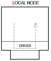
Device Loopback Test
The device loopback test, shown in Figure A.2 determines whether the driver can communicate with the device itself by means of the device registers and interrupts.
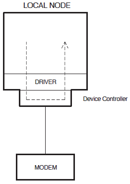
Local Loopback Test
The local loopback test, shown in Figure A.3, verifies that the device is capable of transmitting and receiving data. The test also confirms that the hardware from the host to the modem (that is the device and cable) is operational.
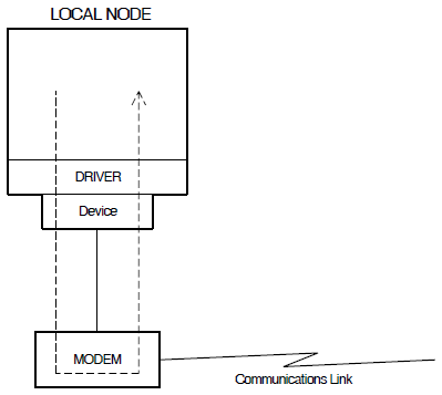
Automatic switching of the modem into local loopback requires that both the modem and the device support circuit CCITT 141, Local Loopback Request. If this is not the case, then manual intervention is required. Refer to the documentation accompanying the device for a description of the supported circuits for each device.
This test will fail if no cable is available, or if the modem is not capable of being looped back under the modem control. If the test fails, you should insert a loopback connector and perform a connector loopback test.
Remote Loopback Test
The remote loopback test, shown in Figure A.4, determines whether communications exist between the local and the remote modem.
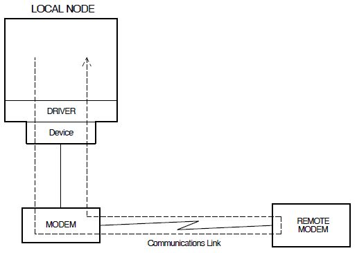
Automatic switching of the modem into remote loopback requires that both the modem and device support circuit CCITT 140, Remote Loopback. If this is not the case, then manual intervention is required. Refer to the documentation accompanying the device for a description of the supported circuits for each device.
This test will fail if no cable is available, or if the modem is not capable of being looped back under the modem control. If the test fails, you should either insert a loopback connector and perform a connector loopback test or manually switch the remote modem into loopback mode and perform an external loopback test.
A.1.1. Preparing the Line for Loopback Testing
ncl> show lapb link * physical linencl> disable lapb link link-nameIt should now be possible to loop data to test the Modem Connect Line.
A.1.2. Performing the Loopback Test (OpenVMS I64 and OpenVMS Alpha)
$ @sys$startup:x25$loopline line-name modeIf the particular loopback mode is supported by the synchronous hardware and modems and the system is operating correctly, there should be no failures reported from the script. If failures are reported, try a different loopback mode, in order to determine where the problem is occurring.
A.1.3. Performing the Loopback Test (OpenVMS VAX)
To test the line on an OpenVMS VAX system, you must enter a series of NCL commands similar
tothe commands in the X25$LOOPLINE.COM file (see Section A.1.5). This file is not supplied with X.25 for OpenVMS VAX.
A.1.4. Returning the Line to Active Service
ncl> enable lapb link link-nameA.1.5. X25$LOOPLINE.COM Source Listing
X25$LOOPLINE.COM file supplied
on OpenVMS I64 and OpenVMS Alpha systems. (If you want to see more NCL output,
omit the DEFINE/USER
commands).$!++
$! ARGUMENTS:
$!
$! P1 - Modem Connect Line which is to be loopback tested
$! the line must not have any other clients (i.e. users
$! of the line must have been disabled) (instance name only,
$! (i.e., PBXDD-0-1, dte-0)
$!
$! P2 - Loopback mode (e.g. driver, device, connector,
$! local, remote, external)
$!--
$!
$!
$! setup any logical/symbols that we need
$!
$ ncl = "$sys$system:NCL"
$!
$! Set the Modem Connect Line into the appropriate loopback mode
$!
$ define/user sys$output nl:
$ define/user sys$error nl:
$ ncl startloop modem connect line 'P1' mode 'P2'
$!
$! startup MOP if we need to
$!
$ define/user sys$output nl:
$ define/user sys$error nl:
$ show process net$mop
$ if $severity .ne. 1
$ then
$ @sys$system:startup network mop
$ started_mop = 1
$ else
$ started_mop = 0
$ endif
$!
$! Create and enable the HDLC entities which we will use to test the Modem Connect
$! Line.
$!
$ define/user sys$output nl:
$ define/user sys$error nl:
$ ncl
create hdlc
create hdlc link loop
create hdlc link loop logical station loop
exit
$ define/user sys$output nl:
$ define/user sys$error nl:
$ ncl set hdlc link loop physical line modem connect line ’P1’
$ define/user sys$output nl:
$ define/user sys$error nl:
$ ncl
! In case we are running over an SCC restrict the packet size
set hdlc link loop maximum data size 1018, pref maximum data size 1018
enable hdlc link loop
enable hdlc link loop logical station loop
exit
$!
$! Create and enable MOP entities used for testing the line
$!
$ define/user sys$output nl:
$ define/user sys$error nl:
$ ncl
create mop circuit loop type = hdlc
set mop circuit loop link name = hdlc link loop logical station loop
enable mop circuit loop func = { loop requester }
create mop client test
set mop client test circuit = loop, address = {00-11-22-33-44-55}
exit
$!
$! Perform the loopback tests
$!
$ set verify
$ ncl loop mop client test length=1, count=100
$ ncl loop mop client test length=571, count=1
$ set noverify
$!
$! Delete all created HDLC and MOP entities created for the line test
$!
$ define/user sys$output nl:
$ define/user sys$error nl:
$ ncl
delete mop client test
disable mop circuit loop
delete mop circuit loop
disable hdlc link loop logical station loop
disable hdlc link loop
delete hdlc link loop logical station loop
delete hdlc link loop
delete hdlc
exit
$!
$! shutdown mop if we need to
$!
$ if started_mop .eqs. 1
$ then
$ stop net$mop
$ endif
$!
$! set the modem connect line back to normal
$!
$ define/user sys$output nl:
$ define/user sys$error nl:
$ ncl stoploop modem connect line 'P1'Appendix B. Clear Cause Codes
Note
The Cause Codes presented in Table B.1 apply only to calls made over public networks; they do not apply to calls made over a private network or over a point-to-point link.
Cause Code 0 indicates that the call was cleared by either the local or the remote DTE. All other Cause Codes indicate that the call was cleared by the network.
|
Clear Cause Code |
PAD Cause Code |
PAD Cause Message |
Description and Action |
|---|---|---|---|
|
0 |
Description: The call has been cleared by either the local or the remote DTE. Action: Examine the diagnostic code for the reason why the call was cleared. Refer to documentation supplied with the clearing DTE for further details of the diagnostic code. | ||
|
0 |
DTE |
Remote request |
Description: The call has been cleared by the remote DTE. Action: Examine the diagnostic code for the reason why the call was cleared. Refer to documentation supplied with the remote DTE for further details of the diagnostic code. |
|
1 |
OCC |
Number busy |
Description: The called DTE cannot process your call request at this time. Action: Attempt the call again at a later date. |
|
3 |
INV |
Invalid facility requested |
Description: The requested facility is not valid or cannot be used as it has not been subscribed to. Action: Examine the diagnostic code to determine which facility is in error and then change the appropriate Template attribute accordingly. If the requested facility has not been subscribed to, contact your PSDN. |
|
5 |
NC |
Temporary Network Problem |
Description: There is a temporary problem that is not allowing the call to proceed. Action: Examine the diagnostic code to determine why the call cannot proceed at this time. Refer to the PSDN documentation describing the diagnostic codes. Attempt to make the call again at a later date. |
|
9 |
DER |
Number out of order |
Description: The called DTE cannot be contacted as there is a problem at the remote DTE. Action: Continue problem solving on the remote DTE. |
|
11 |
NA |
Access to this number is barred |
Description: The DTE number specified was incorrect or you are not permitted to access the specified DTE. Action: Verify that the correct DTE number was specified. If the correct number was specified, contact your PSDN to change your subscription details to allow access to the number. |
|
13 |
NP |
Number not assigned |
Description: The DTE number specified was incorrect. Action: Attempt the call again using the correct DTE number. |
|
17 |
RPE |
Network detected remote procedure error |
Description: There is a problem with the Call packet, or a problem at the remote DTE has been detected by the network. Action: Examine the diagnostic code to determine the exact reason why the call was cleared. Refer to the PSDN documentation describing the diagnostic codes. |
|
19 |
ERR |
Network detected local procedure error |
Description: There is a problem with the Call packet, or a problem at the local DTE has been detected by the network. Action: Examine the diagnostic code to determine the exact reason why the call was cleared. Refer to the PSDN documentation describing the diagnostic codes. |
|
21 |
ROO |
Cannot be routed as requested |
Description: The called number cannot be contacted via the RPOA specified in the RPOA facility. Action: Verify that the RPOA Sequence attribute in the template correctly identifies the intended RPOA. If the attribute is correct, examine the diagnostic code for further information about the reason that the RPOA could not forward the call to the destination DTE. If the diagnostic indicates that the error is temporary, attempt the call again at a later date. |
|
25 |
RNA |
Reverse charging refused |
Description: The reverse charging facility is not valid in this situation or cannot be used as it has not been subscribed to. Action: Attempt the call again without specifying reverse charging. If reverse charging has not been subscribed to, contact your PSDN to update your subscription details. |
|
33 |
ID |
Incomplete destination |
Description: An incomplete destination has been specified for the call. Action: Examine the diagnostic code for the reason why the call was cleared. Refer to documentation supplied with the remote DTE for further details of the diagnostic code. |
|
41 |
FNA |
Fast select refused |
Description: The fast select facility is not valid in this situation or cannot be used as it has not been subscribed to. Action: Attempt the call again without specifying fast select. If fast select has not been subscribed to, contact your PSDN to update your subscription details. |
|
57 |
SA |
Ship cannot be contacted |
Description: The called DTE cannot be contacted as the ship is currently out of range. Action: Attempt the call again at a later date. |
Appendix C. Diagnostic Codes
The X.25 Diagnostic Codes used by X.25 for OpenVMS are given in Table C.1. These codes are based on the CCITTX.25 recommendation and the ISO 8208 specification.
|
Code |
Description |
|---|---|
|
0 |
Non–specific |
|
1 |
Invalid P (S ) |
|
2 |
Invalid P (R ) |
|
16 |
Packet type invalid |
|
17 |
Packet type invalid for state R1 |
|
18 |
Packet type invalid for state R2 |
|
19 |
Packet type invalid for state R3 |
|
20 |
Packet type invalid for state P1 |
|
21 |
Packet type invalid for state P2 |
|
22 |
Packet type invalid for state P3 |
|
23 |
Packet type invalid for state P4 |
|
24 |
Packet type invalid for state P5 |
|
25 |
Packet type invalid for state P6 |
|
26 |
Packet type invalid for state P7 |
|
27 |
Packet type invalid for state D1 |
|
28 |
Packet type invalid for state D2 |
|
29 |
Packet type invalid for state D3 |
|
33 |
Unidentifiable packet |
|
34 |
One way outgoing LCN |
|
36 |
Unassigned LCN |
|
38 |
Packet too short |
|
39 |
Packet too long |
|
40 |
Invalid GFI |
|
41 |
Non–zero LCN in RESTART packet |
|
42 |
Packet incompatible with facility |
|
43 |
Unexpected Interrupt Confirm received |
|
44 |
Unexpected Interrupt received |
|
45 |
Unexpected Reject received |
|
49 |
Timer expired for CALL |
|
50 |
Timer expired for CLEAR |
|
51 |
Timer expired for RESET |
|
52 |
Timer expired for RESTART |
|
64 |
General call set–up problem |
|
65 |
Facility/Registration code not allowed |
|
66 |
Facility parameter value invalid |
|
67 |
Invalid called DTE address |
|
68 |
Invalid calling DTE address |
|
69 |
Invalid facility length |
|
70 |
Incoming call barred |
|
71 |
No logical channel available |
|
72 |
Call Collision |
|
83 |
Inconsistent Q–bit setting in M–bit sequence |
|
128? |
No application to accept call |
|
145 |
Interrupt timer expired |
|
163 |
DTE resource constraint |
|
165 |
M–bit set on partially full data packet |
|
166 |
D–bit not supported |
Appendix D. Reporting Problems to VSI
D.1. Introduction
If the system fails and you believe that the failure is caused by the X.25 software, contact VSI for information about the variety of service options available to you and the procedures for submitting software problem reports. This appendix describes the information you should include with your report.
D.2. Details of the Software
Specify the full name of the X.25 software product you are using.
Specify the software version number.
D.3. Details of the Problem
Clearly define the problem.
State:Whether or not the problem is consistently reproducible, and if so, how to reproduce the problem.
How frequently the problem occurs.
Whether there are any factors related to the problem, for example, heavy use of the system, low line-speed, or the use of particular communication devices.
- Give the priority of the problem.
Priority 1
Major loss of functions. For example, your X.25 system fails to establish any X.25 connections, or X.25 consistently crashes the system.
Priority 2
Some loss of functions. For example performance degradation, data transfer rate falls by a considerable amount.
Priority 3
Some impact on the user, manual intervention required. For example, you need to use an NCL command when there is a DTE or line failure, to turn the line off and back on again.
Priority 4
Functions can run with no significant impact on the user, problem can easily be worked around. For example, you may only need to alter the order in which certain NCL commands are entered.
Priority 5
No system modifications needed to return to normal functions. For example, you have a suggestion, want some advice, or find a documentation error.
- Give additional information:
- Details of your hardware configuration:
Details of CPU type.
Details of all the communication devices (revision levels and speeds) on the CPU.
CSR and vector addresses of the device you are using.
These are listed in the Site Management Guide.
- Details of your software configuration:
- A listing of the following NCL commands (as appropriate for your system's entities):
ncl>show x25 access allncl>show x25 access dte class * allncl>show x25 protocol allncl>show x25 protocol dte * allncl>show lapb allncl>show lapb link * allncl>show modem connect allncl>show modem connect line * allncl>show llc2 allncl>show llc2 sap * allncl>show llc2 link * allncl>show xot allncl>show xot sap * allncl>show xot link * allncl>show x25 relay allncl>show x25 relay client * allncl>show x25 server allncl>show x25 server client * all
Exact details of any event messages and error messages displayed.
If the problem occurs each time a particular user program is run, please submit the sources of the program on media.
If the problem concerns a line error or a protocol error at Level 2 or Level 3, use CTF to record line traffic, and submit the binary file obtained. If you have a line monitor, you can increase the speed of problem detection by submitting a line monitor trace (either as a listing, or on media), giving details of the type of line monitor used.
If the system fails or you need to force a system crash, submit the system dump file with your problem report (not the analyzed output).
For details of how to force a system crash, please refer to the OpenVMS system documentation.
D.4. Copying System Dump Files
$BACKUP SYS$SYSTEM:SYSDUMP.DMP[filenames]/IGNORE=BACKUP -_$MUA0:name/SAVE/REWIND
where filenames is a list of the files containing any additional information that you are providing, and name is the name you give the saveset.
$BACKUP SYS$SYSTEM:SYSDUMP.DMP[filenames]/IGNORE=BACKUP -_$device:name/SAVE/INIT
where filenames is a list of the files containing any additional information that you are providing, and name is the name you give the saveset.
For more information on using BACKUP, refer to the OpenVMS System Management Utilities Reference manual.
This code is specific to X.25 for OpenVMS. Its meaning will vary from vendor to vendor.