VSI X.25 for OpenVMS Management Guide
- Software Version:
- VSI X.25 for OpenVMS Version 2.1
- Operating System and Version:
- VSI OpenVMS IA-64 Version 8.4-1H1 or higher
VSI OpenVMS Alpha Version 8.4-2L1 or higher
Preface
The information in this manual applies to the X.25 functionality provided by VSI X.25 for OpenVMS and VSI DECnet-Plus for OpenVMS VAX. Note that the X.25 functionality in VSI DECnet-Plus for OpenVMS VAX was formerly provided by VAX P.S.I. software.
Throughout this guide, the X.25 functionality by both VSI X.25 for OpenVMS and VSI DECnet-Plus for OpenVMS VAX is referred to generically as X.25 for OpenVMS.
1. About VSI
VMS Software, Inc. (VSI) is an independent software company licensed by Hewlett Packard Enterprise to develop and support the OpenVMS operating system.
2. Intended Audience
This manual is for network managers who are familiar with networking concepts and DECnet-Plus Phase V.
X.25 communications
Local Area Networks (LANs)
Wide Area Networks (WANs)
Installation of software products on your system
The DECnet-Plus software used on the X.25 system
You are familiar with DECnet-Plus terminology
You have read the VSI DECnet-Plus for OpenVMS Network Management Guide manual
You have read the VSI DECnet-Plus for OpenVMS Introduction and User's Guide
3. Document Structure
Part I contains conceptual information on the components of an X.25 system.
Part II contains task–oriented information showing how to manage an X.25 system and the management tools available.
Part III contains information on the facilities that allow you to monitor an X.25 system.
Appendix A describes each of the system–wide logicals used by X.25 for OpenVMS.
Appendix B describes the optional facilities that may be offered by PSDNs.
Appendix C describes the optional facilities of Closed User Groups (CUGs) and Bilateral Closed User Groups (BCUGs) supported.
Appendix D describes the DTE parameters supported by X.25 for OpenVMS.
4. Related Documents
The following sections describe VSI DECnet-Plus for OpenVMS, VSI X.25 for OpenVMS, and VSI OpenVMS manuals that either directly describe the X.25 for OpenVMS software or provide related information.
VSI DECnet-Plus for OpenVMS Documentation
VSI DECnet-Plus for OpenVMS Introduction and User's Guide
This manual provides general information on DECnet-Plus and describes the concept of packet switching data networks.
VSI DECnet-Plus for OpenVMS Installation and Configuration
This manual describes how to install and configure VSI DECnet-Plus for OpenVMS software. For OpenVMS I64 and OpenVMS Alpha systems, this manual also describes how to install X.25 for OpenVMS software. Details on configuring X.25 for OpenVMS on OpenVMS I64 and OpenVMS Alpha systems are provided in the VSI X.25 for OpenVMS Configuration manual. For OpenVMS VAX systems, this manual also describes how to install and configure the X.25 functionality provided by VSI DECnet-Plus for OpenVMS VAX.
VSI DECnet-Plus for OpenVMS Network Management Guide
This manual provides conceptual and task information about managing and monitoring a DECnet-Plus network. In addition, the manual devotes a section to the management of X.25 entities used by DECnet operating over X.25 data links.
VSI DECnet-Plus for OpenVMS Network Control Language Reference Guide
This manual provides detailed information on the Network Control Language (NCL), which is used to manage X.25 for OpenVMS management entities.
VSI X.25 for OpenVMS Documentation
VSI X.25 for OpenVMS Configuration (OpenVMS I64 and OpenVMS Alpha)
This manual explains how to configure X.25 for OpenVMS software on OpenVMS I64 and OpenVMS Alpha systems.
VSI X.25 for OpenVMS Security Guide
This manual describes the X.25 Security model and how to set up, manage, and monitor X.25 Security to protect your X.25 for OpenVMS system from unauthorized incoming and outgoing calls.
VSI X.25 for OpenVMS Problem Solving
This manual provides guidance on how to analyze and correct X.25–related and X.29–related problems that may occur while using the X.25 for OpenVMS software. In addition, the manual describes loopback testing for LAPB data links.
X.25 for OpenVMS Programming
This manual describes how to write X.25 and X.29 programs to perform network operations.
X.25 for OpenVMS Programming Reference
This manual provides reference information for X.25 and X.29 programmers. It is a companion manual to the X.25 for OpenVMS Programming.
X.25 for OpenVMS Utilities
This manual describes how to use and manage X.25 Mail and how to use and manage a host–based PAD to connect to a remote system. It also describes how to manage the X.29 communication links used for both of these functions. In addition, this manual explains how to use OpenVMS DCL SET TERMINAL/X29 commands to manage remote host–based or network PADs.
X.25 for OpenVMS Accounting
This manual describes how to use X.25 Accounting to obtain performance records and information on how X.25 is being used on your system.
VSI OpenVMS Documentation
The current HP OpenVMS New Features and Documentation Overview manual
HP OpenVMS DCL User's Manual
VSI OpenVMS DCL Dictionary
HP OpenVMS System Management Utilities Reference Manual
HP OpenVMS System Services Reference Manual
HP OpenVMS Guide to System Security
5. OpenVMS Documentation
The full VSI OpenVMS documentation set can be found on the VMS Software Documentation webpage at https://docs.vmssoftware.com.
6. VSI Encourages Your Comments
You may send comments or suggestions regarding this manual or any VSI document by sending electronic mail to the following Internet address: <docinfo@vmssoftware.com>. Users who have VSI OpenVMS support contracts through VSI can contact <support@vmssoftware.com> for help with this product.
7. Terminology
|
VAX P.S.I. |
X.25 for OpenVMS |
|---|---|
|
VAX P.S.I. |
X.25 for OpenVMS VAX |
|
Access system |
X.25 Client system |
|
Native system |
X.25 Direct Connect system |
|
Multihost system |
X.25 Connector system |
|
Gateway system |
X.25 Connector system |
|
Client system |
A client system of an X.25 Connector system (and therefore a client of the X25 Server management module on the X.25 Connector system.) |
|
Relay Client system |
A client system of an X.25 Relay system (and therefore a client of the X25 Relay management module on the X.25 Relay system.) |
|
Relay–Client |
A shorthand term for an X25 RELAY CLIENT management entity on an X.25 Relay system that contains management information about an actual Relay Client system. |
|
Relay system |
An X.25 Direct Connect or Connector system with the X.25 Relay module enabled. |
|
Server Client system |
Another term for a Client system. |
|
Server–Client |
A shorthand term for an X25 SERVER CLIENT management entity on an X.25 Connector system that contains management information about one or more actual X.25 Client systems. |
For more information about clients, servers, and relays in X.25 for OpenVMS, refer to the VSI X.25 for OpenVMS Configuration manual and the VSI X.25 for OpenVMS Management Guide.
8. Conventions
|
Convention |
Meaning |
|---|---|
|
UPPERCASE and lowercase |
The OpenVMS operating system does not differentiate between lowercase and uppercase characters. Literal strings that appear in text, examples, syntax descriptions, and function descriptions can be entered using uppercase characters, lowercase characters, or a combination of both. In running text, uppercase characters indicate OpenVMS DCL commands and command qualifiers; Network Control Language (NCL) commands and command parameters; other product–specific commands and command parameters; network management entities; OpenVMS system logical names; and OpenVMS system service calls, parameters, and item codes. Leading uppercase characters, such as Protocol State, indicate management entity characteristics and management entity event names. Leading uppercase characters are also used for the top-level management entities known as modules. |
|
|
This typeface is used in interactive and code examples to indicate system output. In running text, this typeface is used to indicate the exact name of a device, directory, or file; the name of an instance of a network management entity; or an example value assigned to a DCL qualifier or NCL command parameter. |
|
|
In interactive examples, user input is shown in
|
|
$ |
In this manual, a dollar sign ($) is used to represent the default OpenVMS user prompt. |
|
CTRL |
In procedures, a sequence such as
CTRL |
|
italic text |
Italic text indicates variables or book names. Variables include information that varies in system input and output. In discussions of event messages, italic text indicates a possible value of an event argument. |
|
bold text |
Bold text indicates an important term or important information. |
|
( ) |
In a command definition, parenthesis indicate that you must enclose the options in parenthesis if you choose more than one. Separate the options using commas. |
|
{ } |
In a command definition, braces are used to enclose sets of values. The braces are a required part of the command syntax. |
|
[ ] |
In a command definition, square brackets are used to enclose parts of the command that are optional. You can choose one, none, or all of the options. The brackets are not part of the command syntax. However, brackets are a required syntax element when specifying a directory name in an OpenVMS file specification. |
Chapter 1. Introduction
1.1. Facilities Provided by X.25 for OpenVMS
Management
Security
Accounting
X.25 and X.29 programming
X.29 access
X.25 mail
Support of the DECnet-Plus Common Trace Facility (CTF)
These facilities are described further in Sections 1.1.1 to 1.1.7.
1.1.1. Management
Basic Mode, which is used to create a basic working configuration. This mode provides a mechanism for configuring a system without the need to have knowledge of, or understand, the entities and attributes used to manage X.25.
Advanced Mode, which is used to create more complex working configurations. This mode of operation requires a good understanding and working knowledge of the entities and attributes used to manage X.25.
X.25 for OpenVMS provides a comprehensive configuration utility that allows you to set up, modify, and maintain the network configuration parameters of your system.
In addition the configuration facility, X.25 for OpenVMS supports the use of the DECnet-Plus Network Control Language (NCL), which can be used to make temporary changes to the configuration of a network.
The remainder of this manual provides an overview of the manageable entities within X.25 for OpenVMS and how to use the configuration program and NCL to manage these entities. Full details of the configuration utility for X.25 for OpenVMS on OpenVMS I64 and OpenVMS Alpha systems, are provided in the VSI X.25 for OpenVMS Configuration manual. Full details of the configuration utility for X.25 for OpenVMS on OpenVMS VAX systems, are provided in the VSI DECnet-Plus for OpenVMS Installation and Configuration manual. Full details of the available NCL commands are provided in the VSI DECnet-Plus for OpenVMS Network Control Language Reference Guide manual.
1.1.2. Security
Protecting your system from unauthorized incoming calls
Preventing unauthorized outgoing calls
For more details on how to secure X.25 for OpenVMS, see the VSI X.25 for OpenVMS Security Guide.
1.1.3. Accounting
Charge users appropriately for their use of X.25 for OpenVMS
Determine the users of X.25 for OpenVMS at any given time
Record all calls and attempted calls
For details on the functionality, management, and use of the accounting utility, see the X.25 for OpenVMS Accounting manual.
1.1.4. X.25 and X.29 Programming
Set up connections to remote DTEs (establish virtual circuits)
Exchange data using SVCs or PVCs
End connections with remote DTEs (clear virtual circuits)
The X.25 interface (for communication with packet–mode DTEs)
The X.29 interface (for communication with remote PADs)
For more information about these programming interfaces, see the X.25 for OpenVMS Programming and the X.25 for OpenVMS Programming Reference manual.
1.1.5. X.29 Access
Access to a remote system from an X.25 for OpenVMS host via the host–based PAD
Configuration of the X.25 for OpenVMS host–based PAD when accessing a remote system
Users to log in to, or to run an application on, an X.25 for OpenVMS host from an X.29 terminal via a remote PAD
Configuration of the remote PAD on an X.25 for OpenVMS host when accessing the host via X.29 from another X.25 for OpenVMS host
If the PAD complies with the 1988 CCITT recommendation, all 22 PAD parameters are supported.
If the PAD complies with the 1984 CCITT recommendation, only PAD parameters 1 to 18 are supported. In addition, some PSDNs may support PAD parameters 19 to 22.
If you are using a dial–in PAD, a full list of the PAD facilities supported can be obtained from your PSDN supplier.
X.25 for OpenVMS complies with the 1988 CCITT recommendation. Details of the PAD parameters supported by X.25 for OpenVMS are provided in the X.25 for OpenVMS Utilities.
1.1.6. X.25 Mail
X.25 Mail is an extension to OpenVMS Mail. X.25 Mail allows users to send mail to, and receive mail from, other systems that implement the Mail–11 protocol over X.25.
Details of using and managing X.25 Mail are provided in the X.25 for OpenVMS Utilities.
1.1.7. Common Trace Facility (CTF)
Suspected configuration problems
Failures while establishing or using network links
Network overload
Poor network performance
For information about using CTF, refer to the DECnet/OSI for OpenVMS – Common Trace Facility Use manual. For information about problem solving techniques for the X.25 for OpenVMS product, see the VSI X.25 for OpenVMS Problem Solving.
1.2. Introduction to X.25 Management
An X.25 for OpenVMS system will need little day–to–day management once X.25 for OpenVMS has been installed and configured. However, you may need to modify the configuration occasionally to meet changing circumstances. You also need to monitor the system to ensure that it is working correctly and providing the best service for its users. For example, you may need to add anew application to a Client system.
Direct Connect system – a system that is connected directly to an X.25 network. A Direct Connect system was formerly known as a Native system in the VAX P.S.I. product.
Connector system – a system that provides a connection to an X.25 network on behalf of one or more Client systems. Communication between a Connector system and each of the Client systems it services is made using the DECnet Gateway Access Protocol (GAP).A Connector system was formerly known as a Multihost system in the VAX P.S.I. product. In the VAX P.S.I. product, the Connector system was also frequently referred to as a Gateway system. This term was usually reserved for dedicated hardware products that provided the functions of a Connector system.
Client system – a system that uses a Connector system to access an X.25 network; a Client system cannot access an X.25 network directly. A Client system was formerly known as an Access system in the VAX P.S.I. product.
See Section 2.5 for a set of example configurations.
1.3. How to Use this Manual
Part I of this manual contains conceptual information on the parts of an X.25 for OpenVMS system. It details the X.25 Management Model (Chapter 2) and describes each part of an X.25 for OpenVMS system( Chapter 3). You should read Part I if you are new to X.25 for OpenVMS and need to know how the parts of an X.25 system interact.
Part II provides details on how to perform management tasks and the X.25 management tools available. Part II provides reference information that can be used whenever you need to carry out a network management task; it is not intended to be read from start to finish.
Examine the Table of Contents to find the section that details the task you want to carry out.
Turn to the specified section and follow the instructions provided.
To complete some tasks (for example, defining a new application) you will need to carry out other tasks in Part III. If this is necessary, you will find cross–references to those secondary tasks.
Part III contains information on how to monitor an X.25 system using event logging and tracing.
X.25 Accounting is described separately in the X.25 for OpenVMS Accounting manual.
X.25 for OpenVMS also provides two other utilities that network managers need to manage and monitor, these being X.25 Mail? and support for X.29. The use and management of these utilities are detailed in the X.25 for OpenVMS Utilities.
Part I. Conceptual Information
Chapter 2. The X.25 Management Model
2.1. Introduction
Any modification that you make to a VSI X.25 for OpenVMS system involves changing the network management information on the system.
The network management information is divided into a set of functional modules. Each module is divided into entities, each entity dealing with a part of that module's function.
For example, the Modem Connect module holds information on all the physical synchronous communications lines attached to a system. A MODEM CONNECT LINE entity in the Modem Connect module contains all the information (such as line speed and current state) on a specific synchronous communications line. A MODEM CONNECT LINE entity therefore needs to be defined for each synchronous communications line on the system.
To manage a system effectively, you need to know which module and associated entity contains the relevant management information. Section 2.2 summarizes the modules and entities used in an X.25 for OpenVMS system and Section 2.3 details the entities associated with each of the modules.
2.2. Modules Used in an X.25 for OpenVMS System
Device module – defines the management of physical devices that are attached to a network and which must load firmware from a host system. This module corresponds to part of the Physical Layer in the OSI reference model.
Modem Connect module – defines the physical synchronous communication lines connecting a system to an X.25 network. This module corresponds to the Physical Layer of the OSI reference model.
LAPB module – defines the data link protocol (Link Access Procedure, Balanced), which is used to exchange frames between a DTE and a DCE. Commonly known as a level 2 protocol in X.25 nomenclature, this module corresponds to the Data Link Layer of the OSI reference model.
CSMA-CD module – defines the management of Ethernet or IEEE 802.3 Local Area Network devices. This data link offers access by carrier–sense and collision detection thus providing equal service to all stations regardless of load. This module, in conjunction with the LLC2 module, corresponds to the Data Link Layer of the OSI reference model.
FDDI module – defines the management of devices conforming to the Digital Network Architecture (DNA)Fiber Distributed Data Interface (FDDI). See the description of the FDDI module in the VSI DECnet-Plus for OpenVMS Network Control Language Reference Guide manual for information about the specific ANSI and ISO standards supported by these devices. This module, in conjunction with the LLC2 module, corresponds to the Data Link Layer of the OSI reference model.
LLC2 module – defines the data link protocol used on Local Area Networks (LANs, such as Ethernet) that conform to the LLC Type 2 standard. This allows systems on a LAN to communicate with each other using X.25. This module, in conjunction with either the CSMA-CD module or the FDDI module, corresponds to the Data Link Layer of the OSI reference model(and is an alternative level 2 protocol in X.25 nomenclature).
XOT module – defines the management of data links using the X.25 over TCP/IP protocol. This protocol enables the transmission of X.25 packets over an existing TCP/IP network using methods described in RFC 1613. From the X.25 point of view, this module corresponds to the Data Link Layer of the OSI reference model (and is an alternative level 2 protocol in X.25 nomenclature). XOT provides a solution for users who may be migrating to a network backbone that supports only TCP/IP, but still have legacy X.25 applications that they must support. See the VSI X.25 for OpenVMS Release Notes and VSI X.25 for OpenVMS Software Product Descriptionfor information about additional software and licensing requirements when using the XOT module.
X25 Protocol module – defines the packet–level protocol, which is used to exchange packets between a DTE and a DCE. It defines the DTEs, PVCs, and CUGs recognized by an X.25 system. Commonly known as the X.25 level 3 protocol or Packet Layer Protocol (PLP) in X.25 nomenclature, this module, in conjunction with the X25 Access module, corresponds to the Network Layer of the OSI reference model.
- X25 Access module – defines the user interface to the X25 Protocol module. It defines:
The parameters that determine which application is to handle an incoming X.25 call
The default parameters for an outgoing call
The parameters that control security on the system
This module, in conjunction with the X25 Protocol module, corresponds to the Network layer of the OSI reference model. It does provide some additional services beyond the scope of the Network Layer that might be more properly classified as Session Control or Presentation Layer functions.
X25 Server module – defines how a Connector system communicates with a Server Client system.
X25 Client module – defines how a Client system is to operate, such as the maximum number of session control connections it can handle at any one time.
X25 Relay module – defines how incoming calls from Relay Client systems are forwarded (relayed) to other Relay Client systems.
2.3. Entities
The following sections show which entities are used in each module and briefly describe the purpose of each entity. Full details of each of these modules and their associated entities are given in the VSI DECnet-Plus for OpenVMS Network Control Language Reference Guide manual.
2.3.1. Device
|
Entity |
Occurrence |
Description |
|---|---|---|
|
DEVICE UNIT |
1 for each physical device on the local node that requires microcode downloading |
Controls the loading and dumping of microcode for a specific communications device. |
2.3.2. Modem Connect
|
Entity |
Occurrence |
Description |
|---|---|---|
|
LINE |
1 for each physical line |
Defines the characteristics of that line, maintains statistics on its use, and maintains status information. |
|
DATA PORT |
1 for each modem connect line in use |
Shows which LAPB entity is using a line, and the current state of that line. |
2.3.3. LAPB
|
Entity |
Occurrence |
Description |
|---|---|---|
|
LINK |
1 for each modem connect line |
Defines the characteristics of a LAPB link, maintains statistics on its performance, and maintains status information. |
|
PORT |
1 for each LAPB link in use |
Shows which X25 PROTOCOL DTE entity is using the LAPB link. |
2.3.4. CSMA-CD or FDDI
|
Entity |
Occurrence |
Description |
|---|---|---|
|
STATION |
1 for each LAN controller |
Identifies the station to which a port is to be opened. |
|
PORT |
1 for each client |
Shows which LLC2 SAP entity is sending and receiving frames through this port. |
2.3.5. LLC2
|
Entity |
Occurrence |
Description |
|---|---|---|
|
SAP (Service Access Point) |
1 for each CSMA–CD or FDDI STATION |
Provides a means for links to be created between systems over the Ethernet. |
|
LINK |
1 for each remote station |
Defines how the LLC2 protocol is used over a LAN link. |
|
PORT |
1 for each link in use |
Shows which X25 PROTOCOL DTE entity is using a link. |
2.3.6. XOT (OpenVMS I64 and OpenVMS Alpha)
|
Entity |
Occurrence |
Description |
|---|---|---|
|
SAP (Service Access Point) |
1 for each TCP/IP interface |
Specifies the TCP/IP interface service access point (SAP) to use when connecting with another system. |
|
LINK |
1 for each remote system |
Defines a remote TCP/IP system with which XOT can communicate. |
2.3.7. X25 Protocol
|
Entity |
Occurrence |
Description |
|---|---|---|
|
DTE |
1 for each data link (LAPB, LLC2, or XOT) |
Defines the facilities supported by a DTE, the default information used to set up X.25 virtual circuits through the DTE, and the link service provider entity providing the level 2 services for a DTE. |
|
PVC |
1 for each PVC that uses a DTE |
Defines the characteristics of a Permanent Virtual Circuit (PVC) and defines the facilities it supports. |
|
GROUP |
1 for each CUG that the local DTE is part of |
Defines the DTEs that make up an X.25 Closed User Group (CUG), and the type of group (normal, bilateral, or outgoing access). |
2.3.8. X25 Access
|
Entity |
Occurrence |
Description |
|---|---|---|
|
APPLICATION |
1 for each application |
Defines the characteristics of an X.25 application and the filters it uses in the X25 Access module. |
|
DTE CLASS |
1 for each class |
Defines which local DTEs handle particular outgoing calls on a Direct Connect or Connector system. The DTE class is specified by the application making the call. For remote DTE classes, defines which Connector systems will be used. |
|
FILTER |
1 or more for each application that takes incoming calls |
Defines the criteria for passing a call onto an application. |
|
REACHABLE ADDRESS |
1 for each NSAP address |
Defines how an NSAP address provided by an application is converted into a DTE address. |
|
PORT |
1 for each virtual circuit |
Shows the state of a virtual circuit in use. |
|
REMOTE DTE |
System dependent |
Defines the security attributes of a remote DTE within a DTE class. This entity is a child entity of the SECURITY DTE CLASS entity. |
|
SECURITY DTE CLASS? |
System dependent |
Defines the security mechanisms used to control incoming and outgoing calls for a DTE class. |
|
SECURITY FILTER? |
System dependent |
Defines the security mechanisms that control access to X25 ACCESS FILTER entities. |
|
TEMPLATE |
System dependent |
Defines the default parameters for making and accepting calls on the system. |
2.3.9. X25 Server
|
Entity |
Occurrence |
Description |
|---|---|---|
|
CLIENT |
1 for each Client system |
Defines a set of values that a Connector system uses to associate incoming calls with one or more Client systems. |
|
SECURITY NODES? |
1 for each set of Client Systems |
Defines the rights identifiers attributed to a set of Client systems. |
2.3.10. X25 Client
The maximum number of session control connections to Connector systems that the Client system can handle concurrently
The session template to be used to handle incoming session control connections from a Connector system. (Although called the session template, this characteristic actually references an OSI TRANSPORT TEMPLATE entity).
2.3.11. X25 Relay (OpenVMS I64 and OpenVMS Alpha)
2.4. Modules and Entities Used in Each Type of X.25 System
| Module | Type of X.25 System | |||
|---|---|---|---|---|
| Client | Direct Connect | Connector |
Relay? | |
|
MODEM CONNECT? |
— |
|
|
|
|
LAPB? |
— |
|
|
|
|
CSMA-CD? |
— |
|
|
|
|
FDDI? |
— |
|
|
|
|
LLC2? |
— |
|
|
|
|
XOT? |
— |
|
|
|
|
X25 PROTOCOL |
— |
|
|
|
|
X25 ACCESS |
|
|
|
|
|
X25 SERVER |
— |
— |
|
— |
|
X25 CLIENT? |
Yes |
— |
— |
— |
|
X25 RELAY? |
— |
— |
— |
|
2.5. Example Configurations
Note
Except as noted, the example configurations shown here are not related to one another.
2.5.1. X.25 Client System Configuration
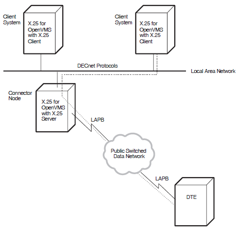
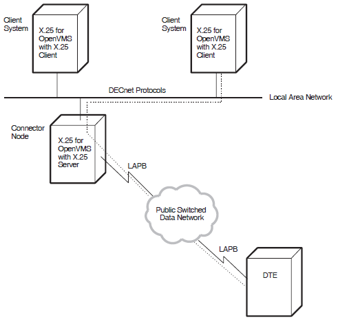
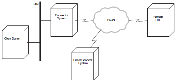
X.25 for OpenVMS allows an X.25 Client system on a DECnet network to connect to PSDNs through one or more X.25 Connector systems, thereby enabling communication between the X.25 Client system and the remote DTEs. The DECnet Gateway Access Protocol (GAP)is used between the X.25 Client system and the X.25 Connector system.
X.25 for OpenVMS Connector system
A dedicated Connector system (see the VSI X.25 for OpenVMS Software Product Description for supported systems).
Figure 2.1 shows an example of two X.25 Client systems that are connected to a PSDN through anX.25 Connector system (that is, an X.25 for OpenVMS system configured as a Connector system).
X.25 for OpenVMS for OpenVMS I64 and OpenVMS Alpha systems require a DECnet-Plus and an X.25 for OpenVMS license to be configured as a Client system. Both DECnet-Plus and X.25 for OpenVMS software must be installed.
X.25 for OpenVMS for OpenVMS VAX systems require only a DECnet-Plus license to be configured as a Client system. DECnet-Plus software must be installed. The VAX P.S.I. Access software option must be selected during DECnet-Plus installation.
2.5.1.1. Sample Client Configuration
It runs three X.25 applications
It uses one Connector system for access to one X.25 network
The Connector system has one DTE class
Table 2.2 shows the minimum number of modules and associated entities that such a system would need (not including the DECnet modules needed for Client–Connector communications).
Module | Entities | Comments |
|---|---|---|
|
X25 ACCESS | X25 ACCESS | |
3 APPLICATION | 1 for each application | |
3 FILTER | 1 for each application | |
1 DTE CLASS | 1 for each DTE class on the Connector system | |
1 TEMPLATE | 1 for each DTE class | |
X25 CLIENT | X25 CLIENT |
2.5.2. X.25 Direct Connect System Configuration
Direct connection over LAPB to one or more PSDNs
Direct connection over LLC2 to one or more DTEs (nodes) on a LAN
Direct connection over XOT to one or more DTEs (nodes) on a TCP/IP network
X.25 for OpenVMS for OpenVMS I64 and OpenVMS Alpha systems require a DECnet-Plus and an X.25 for OpenVMS license to be configured as a Direct Connect system. Both DECnet-Plus and X.25 for OpenVMS software must be installed.
X.25 for OpenVMS for OpenVMS VAX systems require a DECnet-Plus and an X.25 license to be configured as a Direct Connect system. DECnet-Plus software must be installed. The VAX P.S.I. software option must be selected during DECnet-Plus installation.
2.5.2.1. Direct Connection Over LAPB
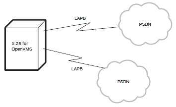
X.25 for OpenVMS allows the direct connection of a node to one or more PSDNs. To achieve this, the physical line between the X.25 for OpenVMS system and the PSDN uses the Link Access Procedure, Balanced (LAPB) link level protocol. This conforms to the CCITT X.25 recommendation and to ISO standards 7776 and 8208.
An example X.25 system connecting directly to two PSDNs is shown in Figure 2.2.
2.5.2.2. Direct Connection Over LLC2
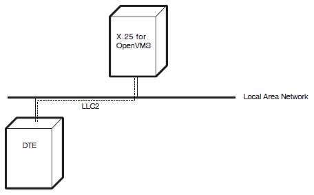
X.25 for OpenVMS can be configured to use the Packet Layer protocol described in ISO 8881 over IEEE 802.2 Logical Link Control, Type II (LLC2) to connect DTEs (nodes) on a LAN. An example showing an X.25 system acting in this mode is shown in Figure 2.3.
2.5.2.3. Direct Connection Over XOT ( OpenVMS I64 and OpenVMS Alpha)
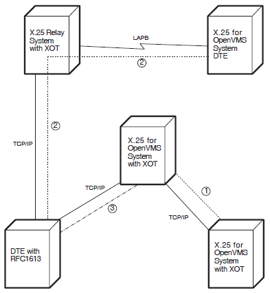
X.25 for OpenVMS can be configured to use the Packet Layer protocol described in ISO 8881 over a TCP/IP network. An example showing an X.25 system acting in this mode is shown in Figure 2.4.
Note
After installing the VSI TCP/IP software, you must run the product's configuration program and enable the PATHWORKS Internet Protocol (PWIP) driver. Refer to the VSI TCP/IP Services for OpenVMS documentation for information about running the configuration program and enabling the PWIP driver. Refer to the VSI X.25 for OpenVMS Release Notes and the VSI X.25 for OpenVMS Software Product Description for information about VSI TCP/IP Services for OpenVMS version and license requirements when using XOT data links.
Path 1 shows a XOT DTE on one X.25 for OpenVMS system accessing a XOT DTE on another X.25 for OpenVMS system in a TCP/IP network. Each system is configured as an X.25 Direct Connect system.
Path 2 shows an local LAPB DTE on a X.25 for OpenVMS Relay Client system in a LAPB network accessing the X.25 Relay functionality on another X.25 for OpenVMS system to use a XOT DTE on the X.25 Relay system to reach a remote DTE with RFC1613 capability in a TCP/IP network. The two X.25 for OpenVMS systems are configured as X.25 Direct Connect systems.
Path 3 shows a remote DTE with RFC1613 capability accessing a XOT DTE on an X.25 for OpenVMS Direct Connect system in a TCP/IP network.
2.5.2.4. Sample Direct Connect Configuration
It runs two X.25 applications
The system has only one DTE
The DTE is a member of single Closed User Group
|
Module |
Entities |
Comments |
|---|---|---|
|
X25 ACCESS |
X25 ACCESS | |
|
2 APPLICATION |
1 for each application | |
|
2 FILTER |
1 for each application | |
|
1 DTE CLASS |
1 for the DTE | |
|
1 TEMPLATE | ||
|
X25 PROTOCOL |
X25 PROTOCOL | |
|
1 DTE |
1 for access to the X.25 network | |
|
1 GROUP |
1 for each DTE | |
|
Link Service Provider (LAPB, LLC2, or XOT) |
LINK |
1 for each line |
2.5.3. Connector System Configuration
An X.25 Connector system provides X.25 server capabilities, allowing a system with direct access to one or more PSDNs to act as a connector system for Client systems.
Using a variety of X.25 Client systems and X.25 Connector systems (which themselves can be Client systems to other Connector systems), many configurations can be created. One typical implementation of an X.25 Connector system is as a LAN node which provides PSDN access for all the X.25 Client systems on the LAN. Figure 2.5 shows an X.25 for OpenVMS system acting as an X.25 Connector system in this implementation.
X.25 for OpenVMS for OpenVMS I64 and OpenVMS Alpha systems require a DECnet-Plus and an X.25 for OpenVMS license to be configured as a Connector system. Both DECnet-Plus and X.25 for OpenVMS software must be installed.
X.25 for OpenVMS for OpenVMS VAX systems require a DECnet-Plus and an X.25 license to be configured as a Connector system. DECnet-Plus software must be installed. The VAX P.S.I. software option must be selected during DECnet-Plus installation. The system should be configured as a Connector system.
2.5.3.1. Sample Connector Configuration
|
Module |
Entities |
Comments |
|---|---|---|
|
X25 SERVER |
X25 SERVER | |
|
2 CLIENT |
1 for each Client system | |
|
X25 ACCESS |
X25 ACCESS | |
|
2 FILTER |
1 for each Client system | |
|
1 DTE CLASS | ||
|
X25 PROTOCOL |
X25 PROTOCOL | |
|
1 DTE |
1 for access to the network | |
|
Link Service Provider (LAPB, LLC2, or XOT) |
LINK |
1 for each line |
2.5.4. X.25 Relay System (OpenVMS I64 and OpenVMS Alpha)
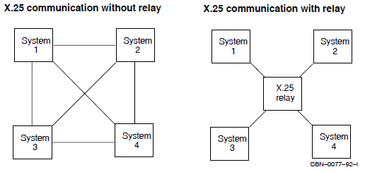
An X.25 Relay system is used to relay (forward) calls from one DTE to another. Figure 2.6 illustrates the principle of X.25 relay operation. Systems 1, 2, 3, and 4 wish to communicate using X.25 data links. In the left diagram, each system sets up a point–to–point X.25 link with every other system. In the right diagram, the same connectivity is achieved, using fewer lines and DTEs, by using an X.25 Relay system. Each system has just one point–to–point link (to the Relay system), and the Relay system switches calls between them as necessary.
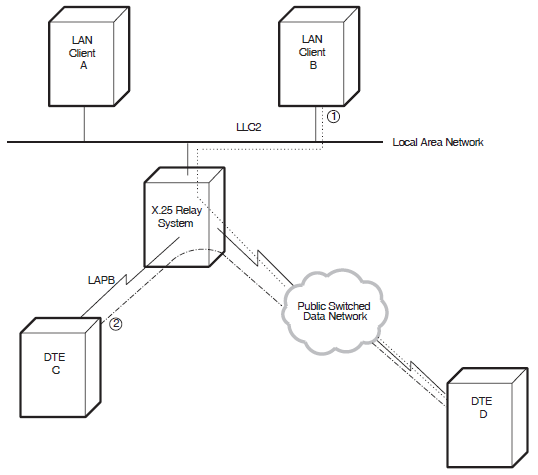
A DTE connected to the X.25 Relay system by means of a Local Area Network (LAN) point–to–point LLC2 data link (or XOT data link on OpenVMS I64 and OpenVMS Alpha systems).
A DTE connected to the X.25 Relay system by means of a Wide Area Network (WAN) point–to–point LAPB data link(or XOT data link on OpenVMS I64 and OpenVMS Alpha systems).
A DTE connected to the X.25 Relay system by means of a LAPB connection to a PSDN.
A LAN DTE and a WAN DTE
Two WAN DTEs - one of which can be a PSDN connection. (However, X.25 Relay does not support relaying between two PSDNs; PSDN authorities require such connections to use X.75 connections).
Two LAN DTEs
Calls to be relayed between LAN Client A or B and DTE D – a LAN–WAN configuration. Path “1” shows the path between LAN Client B and DTE D.
Calls to be relayed between DTE C and DTE D – a WAN–WAN configuration. Path “2” shows the path between DTE C and DTE D.
Table 2.5 shows the modules and entities that such a configuration would need. Note that this example assumes that the direct connect configuration discussed in Section 2.5.2 has already been set up; the modules and associated entities given in Table 2.5 are therefore in addition to the modules and associated entities required to configure the direct connect configuration. This example also assumes that communication takes place in both directions; that is,each DTE in the two paths shown wishes to be able to contact its partner DTE.
For an example of an X.25 Relay configuration using XOT DTEs, see Figure 2.4.
Module | Entities | Comments |
|---|---|---|
For the LAN–WAN Configuration: | ||
X25 RELAY | 2 CLIENT | 1 for each point–to–point connection or PSDN |
X25 ACCESS | 2 FILTER | 1 for each Relay Client |
For the WAN–WAN Configuration: | ||
X25 RELAY | 2 CLIENT | 1 for each point–to–point connection or PSDN |
X25 ACCESS | 2 FILTER | 1 for each Relay Client |
2.5.5. Combination Systems
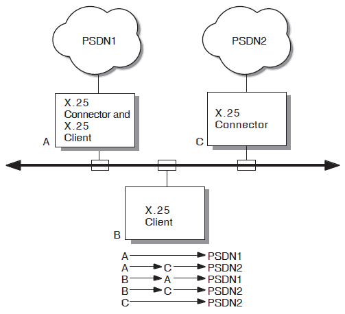
You can configure both Connector and Client functionality on one X.25 for OpenVMS system to attain a combination system. A combination system provides Connector, Direct Connect, and Client capabilities.
System A (acting as a Direct Connect system) accesses PSDN1 directly.
System A (acting as a Client system) accesses PSDN2 through system C (acting as a Connector system).
System B (acting as a Client) accesses PSDN1 through system A (acting as a Connector system).
System B (acting as a Client) accesses PSDN2 through system C (acting as a Connector system).
System C (acting as a Direct Connect system) accesses PSDN2 directly.
Note
You can also configure the X.25 Relay functionality in a Direct Connect or Connector combination system.
Chapter 3. The Components of an X.25 for OpenVMS System
This chapter describes how the major components of a VSI X.25 for OpenVMS system interact. This information will help you set up and manage your system more effectively.
The information in this chapter assumes that you are familiar with the concepts explained in the VSI DECnet-Plus for OpenVMS Introduction and User's Guide.
Section 3.1 provides a summary of the way that an X.25 for OpenVMS system makes and receives calls. The rest of the chapter gives more detailed information about what each of the major components contains, and how each component is used in an X.25 for OpenVMS system. These sections include advice on how to design each component.
This chapter refers to the characteristic attributes of entities. For detailed information on each characteristic attribute, refer to the VSI DECnet-Plus for OpenVMS Network Control Language Reference Guide manual.
While designing your system configuration you should consider its security. For example, you may want to restrict outgoing calls and prevent unauthorized incoming calls. Full details on setting up the security of an X.25 system are provided separately in the VSI X.25 for OpenVMS Security Guide.
3.1. Summary of Call Handling
Applications communicate with one another over virtual circuits established between DTEs. When a pair of applications need to exchange information, one of them will set up the virtual circuit, but both can use it.
When reading the descriptions of call handling you should refer to Figure 3.1.
Note that in the descriptions only switched virtual circuits (SVCs) are considered. Details on the use of permanent virtual circuits (PVCs) are provided in Section 3.2.8. Details on X.25 Relay call handling are provided in Section 3.8.2.1.
3.1.1. Making a Call from a Direct Connect System
The address of the destination DTE to which the call is to be made
The size of packets to be exchanged over the virtual circuit
The window size to be used in packet exchange
The application can supply all the necessary information. However, this means that if the application is used on a number of X.25 systems, separate versions of that application will need to be created so that information specific to each system can be included.
Another way of providing the information is through the X25 ACCESS TEMPLATE entity. By defining an X25 ACCESS TEMPLATE entity for each call destination, an application only needs to specify the name of the appropriate template to make the call.
To set up the call, the X.25 system (the calling DTE) sends a call request packet to the called DTE using the information in the specified template.
When the call has been set up with the remote DTE (and hence the remote application), information exchange can begin.
3.1.2. Receiving a Call on a Direct Connect System
When X.25 for OpenVMS receives an incoming request for an application, the call request packet is received at the destination DTE. The X.25 system then needs to find the appropriate application to process the call.
Note
An application has the option of declaring itself a network process rather than relying on the static application definition found in a X25 ACCESS APPLICATION entity. Network processes can use static filters already defined by existing X25 ACCESS FILTER entities or they can create dynamic filters. See the X.25 for OpenVMS Programming for more information about dynamic filters and network processes.
When a call request is received, the call parameters (for example, the remote DTE address) are matched against the attribute values in the locally–defined filters; only filters that are being listened to will be matched, and they will be matched in the order specified by the filters' Priority attributes. If a filter is found that matches the call parameters, the call request is passed to the application that is listening to that filter.
Each application that can receive calls must have at least one filter associated with it. The attributes of this filter must be distinct enough to ensure that the application gets called at the correct time. Filters cannot be shared between applications.
3.1.3. Making a Call from a Client System
A Connector system provides a connection to one or more X.25 networks on behalf of one or more Client systems. Communication between a Connector system and each of the Client systems it services is made using the DECnet Gateway Access Protocol (GAP). The Connector system therefore makes and receives calls on behalf of the Client systems it services.
When making a call from a Client system, it is the Connector system's responsibility to establish a virtual circuit to the requested remote DTE on behalf of the Client system. The Client system is responsible for passing the call parameters to the Connector system and for enforcing any security restrictions on the call.
Call parameters, such as the DTE class and destination address, must be specified for each call. Like calls from a Direct Connect system, such parameters can be supplied by the application requesting the call or in a template.
To set up the call, the Client system sends a call request packet to the Connector system. The DECnet Gateway Access Protocol(GAP) is used between the Client system and the Connector system. The Connector system then forwards the request to the called (remote) DTE using the information in the specified template.
When the call has been set up with the remote DTE (and hence the remote application), information exchange can begin.
3.1.4. Receiving a Call on a Client System
When a Connector system receives a call request packet from a remote DTE, it needs to determine which Client system to forward the call on to. To do this, the Connector system uses filters to determine which calls should be forwarded to which Client system. One or more filters can be associated with each Client system, however, each filter cannot be associated with more than one Client system.
The filter on the Connector system simply forwards an incoming call request to the appropriate Client system; the filter does not determine which application on the Client system should accept the call or whether there is any application to accept the call. It is the responsibility of the Client system to determine which calls it will accept and which application each accepted call is passed on to.
To do this, the Client system also uses filters. Each filter is an instance of the X25 ACCESS FILTER entity, and contains values for various parts of the received call setup information. Each application that can receive calls has an X25 ACCESS APPLICATION entity that defines the name of the application and the names of its associated filters. (See the note in Section 3.1.2 for an alternative method of declaring applications and their filters).
When a call request is received, the call parameters (for example, the remote DTE address) are matched against the attribute values in locally–defined filters. The mechanism by which this is achieved is identical to that used when a call request is received on a Direct Connect system. Refer to the description of this mechanism in Section 3.1.2.
3.2. DTE Classes, DTEs, Links, and Lines
LAPB data links are associated with a physical line that connects the X.25 system to Data Circuit–terminating Equipment (DCE). The DCE is the point where all data enters and leaves the X.25 network. X.25 protocols operate over this physical line.
LLC2 data links are associated with a point-to-point connection (using ISO8881) over a LAN using the LLC class II protocol (ISO8802-2).
XOT data links are associated with a point-to-point connection (using ISO8881) over a TCP/IP network as defined in RFC 1613.
On X.25 systems, individual DTEs are grouped in DTE Classes. DTE classes make it easier for applications to make outgoing calls. This is because applications can reference all DTEs in a DTE class without having to be aware of the actual DTE configuration. This provides more flexibility in system configuration. Actual DTE definitions can change while the DTE class name remains unchanged.
An X.25 Client system does not directly support DTEs. Instead, it uses a special type of DTE class to designate the X.25 Connector system to use for X.25 access. See the description of a remote DTE class in Section 3.2.1.2.
A DTE can also belong to a Closed User Group (CUG). A CUG defines a group of DTEs located anywhere in the network that are allowed to communicate only with each other, rather than with any DTE in the network. A CUG therefore restricts calls to calls between CUG members. The identification of the CUG is determined by the network provider. Groups are associated with Direct Connect and Connector systems; not with Client systems.
DTEs can have Permanent Virtual Circuits (PVCs) associated with them. Such virtual circuits are set up permanently, that is, no call setup phase is required before data can be exchanged over a PVC. PVCs are associated with Direct Connect and Connector systems; not with Client systems.
DTE classes
DTEs
LAPB links and their associated lines
LLC2 links and their associated CSMA-CD and FDDI stations
XOT links (OpenVMS I64 and OpenVMS Alpha)
PVCs
Groups
3.2.1. DTE Classes
On X.25 for OpenVMS systems, individual DTEs are grouped in DTE classes. DTE classes make it easier for applications to make outgoing calls. This is because a single template can be used for all the DTEs in a DTE class; applications therefore do not need to decide which DTE to use since the first DTE in the DTE class with available capacity is used. In many systems, each DTE class contains just one DTE, but a DTE class can contain many DTEs. In general, a DTE class is set up for each X.25 network that an X.25 system will access.
Local DTE Classes exist on X.25 systems that are connected directly to X.25 networks (or directly to other X.25 systems using LLC2 or XOT data links). Therefore, local DTE classes exist on Direct Connect and Connector systems.
Remote DTE Classes exist on X.25 systems that are connected indirectly to X.25 networks, that is, the X.25 system is connected via another system to the X.25 network. Therefore, remote DTE classes exist on Client systems that gain access to an X.25 network via a Connector system.
| Characteristic | Description |
|---|---|
|
DNIC |
Specifies first part of the network user address (NUA). Specify either a 4-digit data network identification code (DNIC) or a 3-digit data country code (DCC). |
|
International Prefix |
Specifies the first digit of an X.121 address to indicate an international or internetwork call. |
|
Local Prefix |
Specifies the first digit of an X.121 address to indicate a local call. |
|
Strip DNIC |
Specifies whether the first part of the network user address (NUA) (the DNIC or DCC as specified by the DNIC attribute) should be stripped for outgoing calls and stripped from the NUA presented to the local DTE for incoming calls. |
|
Type |
Specifies the type of DTE class. See the two subsection that follow for more information. |
3.2.1.1. Local DTE Classes
Each local DTE class contains a list of one or more DTEs defined locally on an X.25 Direct Connect or Connector system. Each DTE is associated with its own physical device and its own Level 2 link used over the connection to the DCE.
The local DTE class is a variety of the X25 ACCESS DTE CLASS entity with its Type attribute
set to local.
If the local DTE classes on a Connector system are used by Client systems to gain access to the X.25 network, a Server–Client is needed on the Connector system for each Client system that can use its local DTE classes. Refer to Section 3.7 for information on Server–Clients.
| Characteristic | Description |
|---|---|
|
Local DTEs |
Specifies the names of the X25 PROTOCOL DTE entities that belong to this DTE class.
Note that if an X25 PROTOCOL DTE entity has its State status attribute set to
|
|
Type? |
Specifies the type of DTE class. For local DTE classes this must be set to
|
3.2.1.2. Remote DTE Classes
Each remote DTE class indicates the name of the DTE class and the Connector system or systems on which the DTEs in the class are defined. Using this information, the Client system can establish a connection to the correct Connector system to make an outgoing call.
A remote DTE class is a variety of the X25 ACCESS DTE CLASS entity with its Type attribute set
to remote.
For Phase IV Connector systems, the name specified must be the name of the X.25 network to be used on the Connector system.
For Phase V Connector systems, the name specified must be the same as a local X25 ACCESS DTE CLASS entity on the Connector system.
| Characteristic | Description |
|---|---|
|
Account |
Specifies the account data to use when connecting to the X.25 Server on the X.25 Connector system. |
|
Node |
Specifies the node name of the X.25 Connector system on which the DTEs in this DTE class reside. |
|
Outgoing Session Template |
Specifies the name of an OSI TRANSPORT TEMPLATE entity to be used when connecting to the X.25 Server on the X.25 Connector system. |
|
Service Nodes |
Specifies a set of records describing the nodes of the X.25 Connector systems on
which the DTEs in this DTE class reside. Each record contains a node name and a rating.
Values are entered using the syntax
|
|
Type? |
Specifies the type of DTE class. For remote DTE classes this must be set to
|
|
User |
Specifies the user name to use when connecting to the X.25 Server on the X.25 Connector system. |
3.2.2. DTEs
An X25 PROTOCOL DTE entity holds all the attributes for a DTE. One X25 PROTOCOL DTE entity exists for each DTE defined on an X.25 system. Table 3.4 lists the characteristic attributes of a DTE (that is, those attributes that you can modify using NCL). For further details of these attributes, their values, and their default values, refer to the VSI DECnet-Plus for OpenVMS Network Control Language Reference Guide manual. Note that most of these values are defined in the network profile being used; you do not need to specify a value explicitly.
| Characteristic | Description |
|---|---|
|
Call Timer? |
Specifies the elapsed time, in seconds, before which outgoing calls from the DTE that have received no response are cleared. The default is that the X.25 system waits indefinitely for a response and never clears the call. |
|
CCITT Version |
Specifies the version of the CCITT X.25 recommendations to which the DTE conforms. |
|
Clear Timer? |
Specifies the value of the retransmit timer for outgoing clear packets from the DTE. |
|
Default Packet Size? |
Specifies the default size (in bytes) of packets for all virtual circuits that the DTE handles. |
|
Default Window Size? |
Specifies the default size of the window for all virtual circuits that the DTE handles. |
|
Description |
Specifies the manufacturer, product name, and version of the hardware platform of the DTE. This characteristic cannot be modified. |
|
Extended Packet Sequencing? |
Determines whether the DTE will use modulo 128 packet sequencing instead of the normal modulo 8 sequencing. You can enable this attribute only if the X.25 network provides this facility and if you have subscribed to it. |
|
Inbound DTE Class |
Specifies the name of the X25 ACCESS DTE CLASS entity to be associated with all incoming calls on this DTE (refer to Section 3.4 for information on how this value is used). |
|
Incoming List |
Specifies a list of Logical Channel Numbers (LCNs) to use for incoming calls. The list can contain one or more ranges, and each range can contain a single LCN or a range of LCNs. The LCNs that you can use are determined by the X.25 network provider. |
|
Interface Type |
Determines whether the DTE operates as a DTE or a DCE. For connection to a PSDN, this value must be DTE. The values DCE and Negotiated are used only when X.25 protocols are used over a point–to–point link. |
|
Interrupt Timer? |
Specifies the value of the interrupt timer. This timer is started when an interrupt packet is sent. If no interrupt confirmation packet is received before the timer expires, a reset takes place. By default, the X.25 system waits indefinitely for the interrupt confirmation packet. |
|
Link Service Provider |
Specifies the name of the link level entity that the DTE uses. You must give this attribute a value before you enable the DTE entity. For DTEs configured over an LLC2 link, this attribute must specify an LLC2 SAP LINK entity. For DTEs configured over a LAPB link, this attribute must specify a LAPB LINK entity. For DTEs configured over a XOT link, this attribute must specify a XOT SAP LINK entity (OpenVMS I64 and OpenVMS Alpha). |
|
Maximum Active Circuits? |
Specifies the maximum number of virtual circuits (SVCs and PVCs) that can be active at any time on the DTE. |
|
Maximum Clear Attempts? |
Specifies the number of times that a clear packet can be sent unsuccessfully on a virtual circuit on the DTE. By default a clear packet is sent only once; that is, there are no retries. |
|
Maximum Packet Size? |
Specifies the maximum size (in bytes) of packets for all virtual circuits that the DTE handles. |
|
Maximum Reset Attempts? |
Specifies the number of times the DTE attempts to send a reset packet. |
|
Maximum Restart Attempts? |
Specifies the number of times that any virtual circuit on the DTE attempts to send a restart packet. |
|
Maximum Throughput Class? |
Specifies the maximum rate of data transmission for any virtual circuit on the DTE. |
|
Maximum Window Size? |
Specifies the maximum size of the window for all virtual circuits that the DTE handles. |
|
Minimum Packet Size? |
Specifies the minimum packet size, in bytes, for all virtual circuits on the DTE. |
|
Minimum Throughput Class? |
Specifies the minimum rate of data transmission for any virtual circuit on the DTE. |
|
Minimum Window Size? |
Specifies the minimum window size for all virtual circuits on the DTE. |
|
Outgoing List |
Specifies the Logical Channel Numbers (LCNs) to be used on the DTE for outgoing calls. The value is a list of one or more LCN sets, each set containing a single LCN or a range of LCNs. The LCNs that you can use are determined by the X.25 network provider. |
|
Profile? |
Specifies the name of the profile. The profile contains the network characteristics
of the PSDN that VSI is committed to support. It includes frame parameters, packet
parameters, and optional facilities, as described in the
VSI DECnet-Plus for OpenVMS Introduction and User's Guide. The values in the profile provide default values for
many DTE attributes and set the minimum and maximum values that such attributes can have.
For LLC2 and XOT DTEs, the profile name must be ISO8881. For LAPB
point–to–point connections, the profile name must be
|
|
Reset Timer? |
Specifies the value of the retransmit timer for outgoing reset packets from the DTE. |
|
Restart Timer? |
Specifies the value of the retransmit timer for outgoing restart packets from the DTE. |
|
Segment Size |
Specifies the size (in bytes) of data segments from this DTE. This attribute is only used for accounting purposes; it has no effect on the content or format of packets sent by the DTE. |
|
X25 Address |
Specifies the full address of the DTE. You must specify a value for this attribute before you enable the DTE entity. |
3.2.2.1. Designing DTEs
Default Packet Size
Default Window Size
Extended Packet Sequencing
Incoming List
Interface Type
Maximum Packet Size
Maximum Window Size
Outgoing List
X25 Address
Inbound DTE Class
Link Service Provider
X25 Address
A network profile must be specified when the X25 PROTOCOL DTE entity is created. The specified profile contains the subscription information for the X.25 network to which the DTE is connected. Profiles greatly simplify the setting up of X.25 systems. A profile generally contains the default, minimum, and maximum value that can be specified. You are not permitted to define a value outside the specified range. For example, if you attempt to define a window size greater than the maximum value defined in the profile, the window size is set its maximum value. See the description of the Profile attribute in Table 3.4 for more information.
3.2.3. LAPB Links
A physical synchronous communication line between a Direct Connect or Connector system and the X.25 network uses the LAPB link level protocol. This is the link that a DTE uses to access the network. Each LAPB DTE on an X.25 system has its own LAPB link.
| Characteristic | Description |
|---|---|
|
Acknowledge Timer? |
The maximum time (in milliseconds) to wait for acknowledgment of a message. If this time elapses without receiving an acknowledgment, the X.25 system starts error recovery action. |
|
Holdback Timer |
The time (in milliseconds) to wait before sending an acknowledgment to a received message. |
|
Interface Type |
This attribute determines local link operates as a DTE or a DCE. For connection to a PSDN, this value must be DTE. |
|
Maximum Data Size? |
The maximum size (in bytes) of an information field in any I–frame exchanged on the link. |
|
Physical Line |
The name of the MODEM CONNECT LINE entity for the physical line over which the LAPB link is to operate. You can modify this characteristic only when the LAPB LINK entity is disabled. |
|
Poll Timer |
The maximum period (in seconds) that can elapse without frames being exchanged on the Data Link. On expiration, an RR(P) is sent to elicit a response from the other end. |
|
Profile |
The name of the profile that contains subscription information for the network to
which the device is connected. For point–to–point links, specify
|
|
Receive Buffers |
The number of receive buffers allocated to the link. |
|
Retry Maximum? |
The maximum number of times that a frame will be retransmitted before the X.25 system assumes that a fatal error has occurred. At this point, the X.25 system will reset the link and all active virtual circuits. |
|
Sequence Modulus? |
Specifies whether the link uses modulo 8 or modulo 128 frame sequencing. Change the value of this attribute only if your network supports both values, and if you have subscribed to the appropriate network facility. |
|
Window Size |
The size of the window used for sending and receiving I–frames on the LAPB link. The default value of this attribute is determined by the profile (and hence, the network provider). However, you can change it subject to limits of the X.25 network. |
3.2.3.1. Designing LAPB Links
The name of the LAPB link and the network profile must be specified when the entity is created.
An X.25 system can operate as a DTE or a DCE; the method in which it operates is specified in the Interface Type attribute. For connection to a PSDN the Interface Type attribute must be set to the value DTE. The value of this attribute should be set to DCE when X.25 protocols are to be used on a point–to–point link.
Define the name of the MODEM CONNECT LINE entity for the appropriate physical synchronous communication line as the value for the Physical Line attribute. The Physical Line attribute must be specified before enabling the LAPB LINK entity.
A network profile must be specified when the LAPB LINK entity is created. The specified profile contains the subscription information for the X.25 network to which the DTE is connected. Profiles greatly simplify the setting up of X.25 systems. A profile generally contains the default, minimum, and maximum value that can be specified. You are not permitted to define a value outside the permitted range. For example, if you attempt to define a window size greater than the maximum value defined in the profile, the window size is set to its maximum value. Define the network profile for the X.25 network as the value of the Profile attribute.
You can specify a value for the Window Size attribute, but it is subject to limits specified by the X.25 network and values defined in the network profile.
3.2.4. Physical Synchronous Communication Lines
LAPB links represent direct physical connections to the X.25 network using synchronous data lines. The MODEM CONNECT LINE entity defines the attributes for these physical lines. The MODEM CONNECT LINE entity is associated with a physical X.25 line. Lines are used by Direct Connect and Connector systems to associate a synchronous port on a communications device with a physical X.25 line. A MODEM CONNECT LINE entity defines attributes to control and monitor the physical X.25 line with which it is associated.
| Characteristic | Description |
|---|---|
|
Communications Port |
Specifies the communications port to which the line is connected. |
|
Connection Type |
Specifies whether the line is |
|
Communications Mode |
Specifies whether the X.25 line is |
3.2.4.1. Designing Lines
myport, enter the
command:ncl>create modem connect line line-id communications port myport,-_ncl>communications mode synchronous, connection type non-switched
3.2.5. LLC2 Links
A DTE can be configured to run over a LAN using LLC2. The LLC2 module provides reliable point–to–point data links over a LAN using the LLC class II protocol (ISO8802–2).Two systems can communicate with each other over a LAN using X.25 level 3 over an LLC2 data link (ISO8881).
| Characteristic | Description |
|---|---|
|
LAN Station |
Identifies the LAN station entity to which a port is to be opened. The value you give this should be the name of a CSMA–CD or FDDI STATION entity. |
|
Local LSAP Address |
Identifies the local link service access point (LSAP) address that LLC2 will use to
identify X.25 traffic. The default value ( |
| Characteristic | Description |
|---|---|
|
Acknowledge Timer |
The maximum time (in milliseconds) to wait for acknowledgment of a message. If this time elapses without receiving an acknowledgment, the LLC2 system starts error recovery action. |
|
Busy Timer |
The time (in milliseconds) to wait for an indication of the clearance of a busy condition at the remote station. |
|
Holdback Timer |
The time (in milliseconds) to wait before sending an acknowledgment to a received message. |
|
Maximum Data Size |
The maximum size (in bytes) of an information field in any I–frame exchanged on the link. |
|
Local Receive Window Size |
The window size that the local end of the link uses for receiving frames. |
|
Poll Timer |
The time (in milliseconds) to wait for a response with the f–bit set. |
|
Reject Timer |
The time (in milliseconds) to wait for a reply to a REJ frame. |
|
Remote MAC Address |
Identifies the LAN address that the remote system is using. |
|
Remote LSAP Address |
Identifies the link service access point that the remote system is using to identify
X.25 traffic. The default value ( |
|
Retry Maximum |
The maximum times that a frame will be re–sent before the LLC2 system assumes that a fatal error has occurred. At this point, X.25 level 3 will reset all active virtual circuits. |
3.2.5.1. Designing LLC2 Links
The Local LSAP Address matches the Remote LSAP Address at the remote end of the link. Use the default value of
7E.The Remote LSAP Address matches the Local LSAP Address at the remote end of the link. Use the default value of
7E.
3.2.6. LAN Stations
LLC2 data links represent connections to companion systems on a CSMA–CD or FDDI LAN. The CSMA–CD or FDDI STATION entity defines the attributes for LAN connections. The CSMA–CD or FDDI station connects nodes residing on the same LAN. The two point–to–point systems must be running the same data link protocol.
3.2.6.1. Designing CSMA–CD Stations
The CSMA–CD module
A STATION entity that maps to an OpenVMS CSMA–CD controller
ncl>create CSMA-CD STATION station-id communication port device-name
|
station–id |
is the name of the station. Each station corresponds to a particular logical link control (LLC), media access control (MAC) and physical attachment. |
|
device–name |
is the OpenVMS device name to assign to this station. The name must be in the format ddc, where dd is the device name prefix (refer to the current version of the HP DECnet-Plus for OpenVMS Release Notes for a list of Ethernet devices) and c is the controller letter (A, B, C, and so on). |
$show device
3.2.6.2. Designing FDDI Links
The FDDI module
A STATION entity that maps to an OpenVMS FDDI controller
ncl>create FDDI STATION station-id communication port device-name
|
station–id |
is the name of the station. Each station corresponds to a particular logical link control (LLC), media access control (MAC) and physical attachment. |
|
device–name |
is the OpenVMS device name to assign to this station. The name must be in the format ddc, where dd is the device name prefix (refer to the current version of the HP DECnet-Plus for OpenVMS Release Notes for a list of FDDI devices) and c is the controller letter (A, B, C, and so on). |
$show device
3.2.7. XOT Links (OpenVMS I64 and OpenVMS Alpha)
A DTE can be configured to run over a TCP/IP network using the specifications in RFC 1613.The XOT module provides reliable point–to–point data links over a LAN or WAN using the TCP/IP protocols. Two systems can communicate with each other over a TCP/IP network using an X.25 level 3 data link (ISO8881).
| Characteristic | Description |
|---|---|
|
Local IP Address |
Identifies the TCP/IP interface on the host system. The default address of 0.0.0.0 specifies that any available TCP/IP interface may be used. |
|
Local RFC1613 Port Number |
Specifies which TCP port will accept inbound connections. RFC 1613 specifies a default value of 1998. |
3.2.7.1. Designing XOT Links
The Remote IP Address attribute specifies a valid IP address of a system that implements RFC 1613.
The Remote RFC1613 Port Number attribute specifies the TCP port where the remote RFC 1613 implementation is listening for inbound XOT connections.
3.2.8. PVCs
A PVC is a special form of virtual circuit that is permanently established between a pair of DTEs. The circuit is always open and therefore available for data communication.
PVCs exist only on Direct Connect and Connector systems. However, applications on Client systems can request the use of PVCs on a Connector system.
| Characteristic | Description |
|---|---|
|
Channel |
The channel number for the PVC as allocated by the network provider. |
|
Packet Size |
The size (in bytes) of packets exchanged over the PVC. This value must lie between the values of the Maximum Packet Size and Minimum Packet Size attributes of the parent DTE entity. |
|
Window Size |
The size of the window used on the PVC. This value must lie between the values of the Maximum Window Size and Minimum Window Size attributes of the parent DTE entity. |
3.2.8.1. Designing PVCs
You can use PVCs only if you have subscribed to the PVC facility on your X.25 network. You need to determine the name of the PVC,and the network provider will provide the value of the Channel attribute.
You can set values for the Packet Size and Window Size attributes. However, these values must lie between the minimum and maximum values defined for the parent X25 PROTOCOL DTE entity. In addition, they will be subject to any limits imposed by the network provider.
3.2.9. Groups
Facilities are available on many X.25 networks to define DTEs as part of a Closed User Group (CUG) or a Bilateral Closed User Group (BCUG). A further type of group that permits access to DTEs outside the group, known as a Closed User Group with Outgoing Access(CUGOA), can also be defined.
Groups exist only on Direct Connect and Connector systems. However, applications on Client systems can request the use of groups on a Connector system.
| Characteristic | Description |
|---|---|
|
Members |
A list of the DTEs on the local system that are part of the group. There is one entry
in the list for each DTE. Each entry consists of:
In a BCUG, this list has only one entry. |
|
Type |
The type of Group: CUG, CUGOA, or BCUG. |
3.2.9.1. Designing Groups
The only attribute that you have to define for a Group is its name, which you specify when you create the entity. Use a name that reflects the function of the Group.
Most of the remaining information is determined by the network provider. The exception is the name of the DTE that appears in each entry in the Members attribute. This is the name of an X25 PROTOCOL DTE entity that has previously been defined.
3.3. Templates
A template contains the information necessary to make a call from the local X.25 system to another X.25 system. Templates can be defined only for Direct Connect and Client systems.
Generally, a system can contain as many templates as its applications need. At one end of the scale, a system may not have any applications that make outgoing calls. In this case, no templates are needed.
More commonly, the applications do make calls to one or more systems. The number of templates that a system needs will vary. In some cases, one template for each remote DTE will be all that is required. In other cases, multiple templates coping with different criteria such as Call Data, Network Service Access Point (NSAP) mapping, Fast Select, Expedited Data, and Window Size will be necessary.
Creating templates on your system simplifies the task of applications making calls and also simplifies the task of managing the system as a whole. If changes in the calling parameters are required, only the appropriate template needs to be modified, not the applications that use the template.
| Characteristic | Description |
|---|---|
|
Call Data |
A hexadecimal string that identifies the type of call being established to a remote DTE. For the call to be identified, the Call Data value must match that in a filter at the remote X.25 system. The CCITT recommends that all X.29 calls use a Call Data value of
|
|
Calling Address Extension |
The Network Service Access Point (NSAP) address of the calling DTE. |
|
Charging Information |
Specifies whether charging information is included in the call. Modify the value of this attribute only if you want charging information included. |
|
Destination DTE Address |
The full DTE address of the remote DTE. Define this attribute only if all calls using this template are to be sent to the same DTE. |
|
DTE Class |
The name of the X25 ACCESS DTE CLASS entity on the local system to be used to make the call. For Client systems, refer to Section 3.2.1.2. |
|
End–to–End Delay |
Specifies the limits of the acceptable delay to set up a call. The value of this attribute is a range that gives the preferred delay and the maximum delay. Both are decimal numbers that indicate the delay in milliseconds. This attribute is more often used by OSI applications running over X.25 links rather than pure X.25 applications. |
|
Expedited Data |
Determines whether expedited data is requested for the call. |
|
Fast Select |
Determines whether fast select is requested for the call. Values of this parameter allow Fast Select and Fast Select with Response to be specified. In addition, you can specify that Fast Select is not requested or not specified. |
|
Local Facilities |
A hexadecimal string that identifies non–CCITT facilities available in the local DTE class. The string is copied into the call request packet. The interpretation of the string is the responsibility of the application. |
|
Local Subaddress |
A decimal number that is added to the calling DTE address to provide information on the origin of the outgoing call. For example, it could be used to identify the particular node that made the call. The use of this facility and the interpretation of the numbers is the responsibility of the calling and called X.25 systems. |
|
Network User Identity |
A hexadecimal string supplied by the network authority. This is included in the call request packet and is used by the X.25 network for accounting, security, and network management purposes. |
|
NSAP Mapping |
Determines whether the destination DTE address and the DTE class on the local system are held in an X25 ACCESS REACHABLE ADDRESS entity. In this case, the NSAP generated by the application is used to find an X25 ACCESS REACHABLE ADDRESS entity. The values in that entity provide the DTE class and destination DTE address values needed to make the call. If this facility is used there is no need to define the DTE Class and Destination DTE Address attributes in the template. |
|
Packet Size |
The size (in bytes) of packets used in the call. This value is used to determine the
size of packets used if all of the following conditions are true:
If any one of these conditions is false, the value of this attribute is ignored. |
|
Quality of Service |
A hexadecimal string that identifies the quality of service required for the call. The content of the string and its interpretation is the responsibility of the two X.25 systems. |
|
Reverse Charging |
Determines whether reverse charging is requested for the call. That is, the remote X.25 system will becharged for the call by the network authority. Specify this attribute only if reverse charging is available and if you want to use it for all calls that use this template. |
|
RPOA Sequence |
A list of one or more Recognized Private Operating Agency networks that the call is to be routed through. Each network has a unique, 4–digit DTE address. If you use this attribute, define the networks in the order in which they will be used to route the call. |
|
Selected Group |
The name of an X25 PROTOCOL GROUP entity that defines the CUG or BCUG to be used for the call. Use this attribute only if you want all calls using this template to use the appropriate group. In the case of BCUGs, there is no need to specify the Destination DTE Address attribute. |
|
Target Address Extension |
The NSAP address of the remote DTE. This value will be put in the call request packet and can be used at the remote system to match the call with a filter. This value is mainly used for templates that handle calls for OSI Transport. |
|
Throughput Class Request |
The data transmission rate (in bits/s) to be used for the call. The value of this attribute is a range. The first number is the lowest acceptable transmission rate. The second number is the maximum rate. The values that can be used here, and the actual rate employed will depend on the capabilities of the X.25 network. This information is contained in the network profile. |
|
Transit Delay Selection |
The transit delay (in milliseconds) that is acceptable for the call. The value of this attribute is a range. The first number is the minimum acceptable delay, and the second number is the target delay. This attribute will be ignored if the call is made through a DTE that does not have the transit delay selection facility. |
|
Window Size |
The size of the window for packets sent to and received from the X.25 network. The value of this attribute is used if the following conditions are true:
If any one of these conditions is false, the value of this attribute is ignored. |
3.3.1. Predefined Templates
In addition to any templates that you define, the configuration program creates one or more predefined templates, depending on the options you choose as you configure the system. The sections that follow describe the predefined templates.
3.3.1.1. Default Template
The system always creates a template named Default. The
Default template is used if an application does not specify a template. In
this case, the X.25 system uses all the values that the application supplies and then obtains
the remaining values from the Default template.
Default template can be modified to suit local conditions,
that is, it can be tailored specifically for your system. The default template can also be deleted.Caution
The decision to change or delete the Default template should not be
taken lightly as its modification or removal will affect every application that does not specify a template.
3.3.1.2. OSI Transport Template (OpenVMS I64 and OpenVMS Alpha)
The configuration program always creates an additional predefined template called
OSI
      Transport
.This template is referenced by the CONS Template attribute of
the OSI TRANSPORT TEMPLATE entity used when the OSI Transport module is using the CONS network
service provided by X.25 for OpenVMS.
For more information about the use of this template, see the section on configuring X.25 services in the VSI DECnet-Plus for OpenVMS Network Management Guide manual.
3.3.1.3. X.29 Templates (OpenVMS I64 and OpenVMS Alpha)
If you select X.29 support, the configuration program creates two additional templates named
X29Login and X29Server.
The template X29Server is used in the definition of the application
X29_LOGIN. This application services incoming X.29 login requests.
The template X29Login is used when a SET HOST/X29 command is executed and
defines the connection attributes for outbound connections to a remote
X29_LOGIN application.
3.3.2. Designing Templates
You need to carefully choose the number of templates that are required for the applications on the X.25 system. This work should be performed in conjunction with the remote X.25 systems that your system is to call. Those systems will have filters that will accept the incoming call and pass it on to the correct application.
By careful design of the template and filter you can ensure that the correct system is called, that the remote system has all the information it needs to verify that the call originates from an authorized system, and that the call is forwarded to the correct application.
A template can be given any name except for the names used for the predefined templates (see Section 3.3.1).
Specify the remote DTE that the call is to be made to, the DTE class on the local system to make the call, and whether the call is to be routed through one or more RPOAs.
Specify any special facilities to be used in the call.
Provide additional information to help the remote X.25 system correctly filter incoming calls.
The following sections explain which attributes of a template fulfill each of these functions. This information should help you design templates for your system.
3.3.2.1. Call Setup
Explicitly specify these items by using the Destination DTE Address and DTE Class attributes of the template.
Set the NSAP Mapping attribute to
true, and define the appropriate number of X25 ACCESS REACHABLE ADDRESS entities.Set the name of a BCUG in the Selected Group and DTE Class attributes.
The method used for any particular template depends on the type of application that will use it.
In simple cases, where an application always calls a particular remote system, and always uses a particular DTE class on the local system, the first method should be used.
NSAPs and X25 ACCESS REACHABLE ADDRESS entities are used only for those applications that generate NSAPs. In most systems this will be restricted to OSI TRANSPORT.
The final method is used only for BCUGs. In this case, you need to define the Selected Group attribute only. For ordinary groups,you need to define the Destination DTE Address attribute as well so that the correct DTE in the group is selected.
If the call is to be routed through one or more RPOAs, you will also need to specify the RPOAs in the RPOA Sequence attribute.
3.3.2.2. Special Features
Charging Information
End–to–End Delay
Expedited Data
Fast Select
Network User Identity
Packet Size
Reverse Charging
Throughput Class Request
Transit Delay Selection
Window Size
3.3.2.3. Additional Information for Filtering
The remaining attributes can be used by the remote system to assist in filtering the call, and by the pair of applications to help establish the correct service levels.
Call Data
Calling Address Extension
Local Facilities
Local Subaddress
Quality of Service
Target Address Extension
For example, you can use the Call Data attribute to differentiate between various applications that are making calls. You can also use the Local Subaddress attribute to identify the system that has made the call. This is particularly useful where a number of Client systems share a single Connector system.
The Calling Address Extension and Target Address Extension attributes are used for applications that use NSAPs. They correspond to values in filters in the remote system.
3.4. Application Filters
Each call that a Direct Connect or Client system receives must be directed to an application. The system must determine the appropriate application to receive each call. The method of determining the recipient of a call is called filtering. To filter incoming calls the X.25 system uses the X25 ACCESS FILTER entity.
Each X.25 application that can receive calls has at least one filter associated with it. Filters provide the X.25 system with the information to identify which application should receive an incoming call. Section 3.6 shows how a filter is associated with an application.
| Characteristic | Description |
|---|---|
|
Call Data Mask |
A bit mask (specified as a hexadecimal string) that the X.25 system applies to the call user data in the received call packet. The system performs a logical AND operation on the received call user data and this mask. The result of this operation is then compared byte by byte with the value of the Call Data Value attribute of the filter. The call will not be passed to the relevant application if these values do not match. To force the system to match the exact value in the Call Data Value attribute, make each digit in this attribute have the value F. To filter calls using call user data, you must specify a value for this attribute. |
|
Call Data Value |
A hexadecimal string to be matched by this filter. The value matched is the result of an AND operation between the received call user data and the Call Data Mask attribute. To filter calls using call user data, you must specify a value for this attribute and for the Call Data Mask attribute. |
|
Called Address Extension Mask |
A bit mask (specified as a hexadecimal string) that the X.25 system applies to the called address extension (NSAP) specified in the call packet. The system performs a logical AND operation on the NSAP and the mask. The result is compared, byte by byte, with the value of the Called Address Extension Value attribute. The call will not be passed to the relevant application if these values do not match. To force the system to match the exact value in the Called Address Extension Value attribute, make each digit in this attribute have the value F. To filter calls using the called NSAP you must specify a value for this attribute and for the Called Address Extension Value attribute. |
|
Called Address Extension Value |
A hexadecimal string to be matched by this filter. The value compared with this attribute is the result of a logical AND between the Called Address Extension Mask attribute and the called NSAP specified in the call packet. To filter calls using called NSAP, you must specify a value for this attribute and for the Called Address Extension Mask attribute. |
|
Group |
The name of the CUG or BCUG to which the calling DTE belongs. If the calling DTE does not belong to the named group, the call is not passed on to the relevant application. |
|
Inbound DTE Class |
The name of the DTE class that contains the DTE that received the call. If the receiving DTE is not in the named class, the call is not passed on to the relevant application. |
|
Incoming DTE Address |
The incoming call packet contains a field called the Destination DTE Address. This attribute provides a value to be matched with that field. If the values are not identical, the call is not passed on to the relevant application. |
|
Originally Called Address |
If a call is redirected, the DTE address that it originally referenced is put in a field called the Originally Called Address. This attribute provides a value to be matched with that field. If the values are not identical, the call is not passed on to the relevant application. Use this attribute only if you have arranged call redirection facilities with the network provider. It is often used in conjunction with the Redirect Reason attribute. |
|
Priority |
The priority of the filter. Each filter on your system is assigned a priority value. The X.25 system uses these values to determine the order in which filters are searched for matching incoming calls. Matching starts with the filter having the highest priority value first (that is, the largest integer value) followed by the filter having the next highest priority value (that is, the next largest integer value). |
|
Receiving DTE Address |
The DTE address on the local system that actually received the call. If that is not the same as the value of this attribute the call is not passed on to the relevant application. This attribute is provided for backwards compatibility with DECnet Phase IV applications. Phase V applications are recommended to use the Inbound DTE Class attribute to match DTE addresses on the local system. |
|
Redirect Reason |
The X.25 network can redirect a call for a number of reasons. This attribute specifies a particular reason that the application will handle. If the Redirect Reason field in the incoming call is not identical to the value of this attribute, the call is not passed on to the relevant application. Use this attribute only if you have arranged call redirection facilities with the network provider. It is often used in conjunction with the Originally Called Address attribute. |
|
Security Filter |
The name of a security filter used by the X.25 security system to verify the call. The VSI X.25 for OpenVMS Security Guide explains how this attribute is used. |
|
Sending DTE Address |
The Calling Address field in the incoming call contains the address of the DTE that made the call. If specified, the X.25 system compares the value of this attribute with the Calling Address field. If the values are not identical, the call is not passed on to the relevant application. |
|
Subaddress Range |
A set of values of subaddresses that this filter will use to validate a call. Each value in the set can be a single number or a range of addresses. Each of these values corresponds to a Local Subaddress attribute in a template. If specified, the X.25 system attempts to match the subaddress in the incoming call with the value of this attribute. If a match is found, the call is passed on to the relevant application. If no match is found, the call is rejected by the specified filter. |
3.4.1. How Filters Are Used
For each incoming call, an X.25 system searches all its filters in order of filter priority. The system starts with the highest priority filter (that is, the filter whose Priority attribute has the largest integer value) and then works down to the lowest priority filter (that is, the filter whose Priority attribute has the smallest integer value).
If all the attribute values match, the call is passed on to the application associated with the filter.
If any of the attributes do not match, the X.25 system finds the next filter and tries to match its attribute values with those in the call packet.
The X.25 system continues in this way until a match is found or until all filters have been searched. If the system cannot find a matching filter, it rejects the call.
3.4.2. Predefined Filters
The configuration program creates zero or more predefined filters, depending on the operating system and on the options you choose as you configure the system. The sections that follow describe the predefined filters.
3.4.2.1. OSI Transport Filter ( OpenVMS I64 and OpenVMS Alpha)
The configuration program always creates a predefined filter called OSI
Transport.This filter is referenced by the CONS Filter attribute of the OSI
TRANSPORT entity and is used when the OSI Transport module is using the CONS network service
provided by X.25 for OpenVMS.
Note
If you intend to use the CONS network service on an OpenVMS VAX system, you must explicitly configure this filter.
3.4.2.2. X.29 Filter
If you select X.29 support, the configuration program creates a predefined filter named
X29 (on OpenVMS I64 and OpenVMS Alpha systems) or
X29_LOGIN(on OpenVMS VAX systems). This filter is used in the definition
of the application X29_LOGIN.This application services incoming X.29 login
requests.
3.4.2.3. X.25 Mail Filter
If you select X.25 Mail support, the configuration program creates a predefined filter named
X25_MAIL (on OpenVMS I64 and OpenVMS Alpha systems) or
PSI_MAIL(on OpenVMS VAX systems). This filter is used in the definition of
the application X25_MAIL(on OpenVMS I64 and OpenVMS Alpha systems) or
PSI_MAIL (on OpenVMS VAX systems). This application services incoming X.25
Mail requests.
3.4.3. Designing Filters
The filters needed on your system must be designed with care to ensure that valid calls are passed on to the correct applications and to ensure that invalid calls (those calls that are unauthorized or unwanted) are rejected.
You must determine the specific needs of each application in conjunction with the information that valid calling systems can provide. In addition, you need to make sure that invalid calls from other systems on the X.25 network will not be accepted.
Filter priorities determine the order in which filters are matched against the incoming calls. As the X.25 system will pass on a call to the first filter that matches, you must ensure that a call for an application with a higher priority filter (that is, a larger integer value) is not accidentally passed onto an application with a lower priority filter (that is, a smaller integer value). This is why you need to carefully plan the filter values and work in conjunction with whoever is designing the templates for the systems making calls.
A filter can be given any name except for the names used for the predefined filters (see Section 3.4.2).
Addressing attributes
Redirection attributes
Application–dependent attributes
The following sections explain which attributes of a filter make up each of these groups. This information should help you design filters for your system.
3.4.3.1. Addressing Attributes
DTE addresses
NSAP addresses
Groups
The method used for any particular filter depends on the type of application that will use it.
For X.25 applications, you can verify the calling DTE address as well as the DTE class on the local system that receives the call. Specify either or both of the Sending DTE Address and DTE Class attributes as necessary. These attributes can be useful if the remote application always uses the same DTE and the call always arrives on a DTE in a particular DTE class on your system.
Applications that use NSAPs use the Called Address Extension Mask and Called Address Extension Value attributes, as well as various attributes of the OSI TRANSPORT entities.
For applications that communicate as part of a Closed User Group (CUG), only the Group attribute is required. However, it should be specified only if it is important to test for the group identification (for example, if there are particularly sensitive applications that must communicate only through a specific group).
3.4.3.2. Redirection Attributes
If you have arranged call redirection facilities with the network provider you can test for redirected calls in filters. You can use the Originally Called Address attribute to match calls that were originally directed at a specific address. You can also use the Redirect Reason attribute to match calls that were redirected for a specific reason.
For example, a system may have an application that runs only when a specific DTE is unavailable. This could return a message to the calling application notifying it of the failure and asking it to try again later. In this case, the application would have a low priority filter and would use the Originally Called Address and Redirect Reason attributes. The first attribute would specify the DTE address that it acts as messenger for, and the second would specify that it only handles calls if the other DTE has failed.
3.4.3.3. Application–Dependent Attributes
Call Data Mask
Call Data Value
Subaddress Range? (OpenVMS VAX)
The Call Data Mask and Call Data Value attributes correspond to the equivalent attributes in the template. Use these attributes asappropriate to differentiate calling systems or applications. For example, you could use a different call data value for each ofyour applications.
The Subaddress Range attribute? corresponds to the Local Subaddress attribute in a template. You can use this to ensure that an application accepts calls from specific systems. In this case, each calling system would be given its own local subaddress. On the called system, each local subaddress of the calling systems that it will process calls for is included in the value of the Subaddress Range attribute.
3.4.3.4. Attribute Constraints
Call data and called address extension have both data and mask attributes. Data value and mask attributes must be the same length.
They must be of the same length
Performing a logical AND on the value and the mask must result in the original value
|
Value (hex) |
Mask (hex) |
Valid |
|
0010 |
ffff |
yes |
|
0010 |
0030 |
yes |
|
0010 |
ff0f |
no |
|
11 |
f0ff |
no |
|
17af |
ff |
no |
ncl>set x25 access filter myfilter call data value %x01, -_ncl>call data mask %xff
Once this is done you can set either attribute individually, provided that it complies with the above constraints.
3.5. Server–Client Filters
Server–Client filters are filters that are listened to by X25 SERVER CLIENT entities.
A Connector system makes and receives calls on behalf of one or more Client systems. When the Connector system receives a call it needs to know to which Client system to pass the call. (Note: On OpenVMS I64 and OpenVMS Alpha systems, one Server–Client can be used to direct calls to multiple Client systems based on ratings values you define).
Each Connector system maintains information on the Client systems that it serves (refer to Section 3.7). However, the Connector system needs additional information on which calls should be forwarded to each Client system.
Connector systems use filters to determine which calls should be forwarded to Client systems. These filters use the same attributes and need to have the same careful design as Application Filters (refer to Section 3.4).
One or more filters can be defined for each X25 SERVER CLIENT entity.
The Server–Client filter simply passes an incoming call on to a Client system. It does not determine which application on the Client system should accept the call or whether there is any application at all to accept the call. It is still the responsibility of the Client system to determine which calls it will accept and to which application each accepted call is passed.
3.5.1. Designing Server–Client Filters
As a filter that uses the destination DTE information to determine the Client system to forward each call to. In this case, the Connector system acts as little more than a switch. It is up to each Client system to carry out the verification of each call.
As a security front–end processor that carries out additional security validation and so forwards only those calls that are valid for any of its Client systems. In this case, the Connector system protects its Client systems by rejecting invalid (unauthorized) calls.
In the second case, the filters in the Connector system may try to match the exact source of the call, the call user data, the destination, and, on OpenVMS VAX systems, the incoming subaddress. In this way, only valid calls would need to be passed on to the appropriate Client. The filters on each Client system can then be made simpler as all they need to do is determine the correct application to pass the call on to (using call user data or, on OpenVMS VAX systems, the local subaddress).
3.6. X.25 Applications
X.25 applications can be specified for Direct Connect and Client systems.
Note
An application has the option of declaring itself a network process rather than relying on the static application definition found in a X25 ACCESS APPLICATION entity. See the X.25 for OpenVMS Programming for more information about network processes.
If an X25 ACCESS APPLICATION entity's Type attribute is X29 LOGIN, it must,
at minimum, have a value set for its Filters attribute. When a call matches one of the filters,
an X.29 login session is started for the call.
If an X25 ACCESS APPLICATION entity's Type attribute is X25 or
X29, it must, at minimum, have values set for its Filters and File
attributes. When an incoming call matches one of the filters, the system executes the specified
file, passing the details of the call to be processed.
| Characteristic | Description |
|---|---|
|
Account |
The name of the account under which the application is to be run. |
|
Activation Data |
Data required to start up the application. |
|
File |
The name of the command file on the X.25 system that starts the application. This
characteristic is not used if the Type attribute is set to |
|
Filters |
The names of the filters that the application uses. |
|
Maximum Activations |
The maximum number of concurrent activations of the application that can be supported. |
|
Template |
The name of the X25 ACCESS TEMPLATE entity that will be used by the application to accept an incoming call. |
|
Type |
The type of X.25 application. This can be:
|
|
User |
The user name of the account under which the application runs. |
3.6.1. Designing Applications
Declaring an application to the system is straightforward. All you need to do is provide suitable values for attributes of the X25ACCESS APPLICATION entity. In particular, make sure that the Filters attribute has the names of the correct filters. In addition,make sure that the Type attribute is set to the correct value for the application.
Ensure that the name you give to the X25 ACCESS APPLICATION entity reflects the application to which it refers; this will help with future maintenance of your system.
3.7. Server–Clients
A Connector system provides a connection to one or more X.25 networks on behalf of a number of Client systems. This manual uses the term Server–Client to refer to the X25 SERVER CLIENT entity of the X.25 Server that represents the actual Client system(on OpenVMS I64 and OpenVMS Alpha systems, a single X25 SERVER CLIENT entity can represent multiple Client systems).
For security and logistic reasons, the Connector system needs to know which Client systems can use it and how to access each of those systems. For example, a large LAN may have more than one Connector system available and the use of these systems will be divided between the various Client systems.
| Characteristic | Description |
|---|---|
|
Application |
Address information used by the SESSION CONTROL entity on the X.25 Client systems to
select the process that will receive the connection request. This characteristic is always
set to |
|
Filters |
A set of filter names that are used to filter calls for X.25 Client systems represented by this entity. These filters cannot be shared with any other Server–Client on the Connector system. For more information about Server–Client filters, see Section 3.5. |
|
Node |
The full DNS node name of the X.25 Client system represented by this entity. |
|
Password |
The default password to be used for verification when connecting to the X.25 Client systems represented by this entity. |
|
Service Nodes |
A list of full DNS node names of the X.25 Client systems represented by this entity. |
|
User |
The default user identification to be used in access verification when connecting to the X.25 Client systems represented by this entity. |
3.7.1. Designing Server–Clients
The name of one or more filters that the server listens to in order to pick up an incoming call for the Server–Client.
The name of at least one node identifying the X.25 Client system to which the incoming call is directed.
3.7.2. Overview of Server Call Handling
The following two subsections discuss call handling between the X.25 Server process on the Connector node and theX.25 Client process on the Client node.
Overview of Server Operation for Incoming Calls
The remote DTE sends a Call message to the X25 ACCESS module supporting the X.25 Server.
The X25 ACCESS module notifies the X.25 Server of the incoming call.
Based on the existing Server–Client filters, the X.25 Server attempts to establish a DECnet connection with the X.25 Client system associated with the Server–Client with the matching filter.
If the X.25 Client system has been correctly defined and the Client system is willing,the Client system accepts the DECnet connection.
The X.25 Server sends an Incoming Call message.
The Client system processes the Incoming Call request and responds with an Outgoing Accept message.
At this point, both the X.25 Client and the X.25 Server have a circuit state of Running. Normal X.25 operations can now proceed.
Overview of Server Operation for Outgoing Calls
The X.25 Client system initiates a DECnet connection to the X.25 Server.
Session Control on the X.25 Server system informs the X.25 Server of an incoming connection.
Assuming sufficient resources, the X.25 Server accepts the connection.
The Client system sends an Outgoing Call message (including the requested DTE class which represents both a remote DTE class on the Client and a local DTE class on the Server).
The X.25 Server receives the Outgoing Call request and requests that the X25 ACCESS module make an outgoing call.
The X25 ACCESS module places the call using the facilities of the X25 PROTOCOL module (using the DTE class specified by the Client).
Assuming that the call succeeded, X.25 Server sends an Incoming Accept message to the Client system.
At this point, both the Client and the X.25 Server have a circuit state of Running. Normal X.25 operations can now proceed.
3.8. Relay–Clients (OpenVMS I64 and OpenVMS Alpha)
An X.25 Relay system acting as a Connector node allows calls to be relayed between DTEs.
| Characteristic | Description |
|---|---|
|
DTE Class |
The DTE class to use when making the outgoing call. |
|
Filters |
The set of filters that are listened to by this Relay–Client. Each name is the name of an X25 ACCESS FILTER entity. |
|
Template |
The name of the template to be used for the outgoing call. This is the name of an X25 ACCESS TEMPLATE entity. |
3.8.1. Designing Relay–Clients
Although Relay–Client design is very similar for WAN–WAN, LAN–WAN, and LAN–LAN configurations, there are slight variations.
WAN–WAN Configurations –
For outgoing calls you must define one X25 RELAY CLIENT entity for each DTE that is going to make calls to a specified DTE class.
For incoming calls you must define one X25 RELAY CLIENT entity for each DTE that is going to receive calls from a specified DTE class.
LAN–WAN and LAN–LAN Configurations –
For outgoing calls you must define one X25 RELAY CLIENT entity for each set of LAN clients (LLC2 links) that is going to make calls to a specified DTE class.
For incoming calls you must define one X25 RELAY CLIENT entity for each set of LAN clients (LLC2 links) that is going to receive calls from a specified DTE class.
Note that if both outgoing and incoming calls are to be handled, only one X25 RELAY CLIENT entity needs to be defined for each set of LAN clients.
Common Requirements –
The following tasks need to be performed whenever the configuration is being set up.
The name of one or more filters that the X.25 Relay system listens to in order to pick up an incoming call for the Relay–Client. See Section 3.8.2 for more information about how the X.25 Relay system uses filters.
The name of a DTE class that identifies the DTE to which the call is to be relayed.
The name of a template to be used for the outbound call.
3.8.2. Relay–Client Filters
Each Relay–Client listens on a set of filters. Each Relay–Client that can receive calls has at least one filter associated with it. Filters provide the X.25 Relay system with information to distinguish which Relay–Client should receive an incoming call. You need to ensure that incoming calls are directed to the correct Relay Client.
The X.25 Relay system uses the X25 ACCESS FILTER entity to filter incoming calls. This entity has a number of characteristics that contain the filtering parameters.
3.8.2.1. Overview of Call Relaying
Call relaying is a two–stage process. In the first stage, an incoming call is received by the X.25 Relay system from the calling DTE. In the second stage, the received call is relayed to the called DTE.
A call initiated by the calling DTE is received by the X.25 Relay system by listening on a set of filters for specific incoming calls. Calls are received only if they match at least one of the filters.
A separate outgoing call is then initiated by the X.25 Relay system to relay the call to the called DTE. The outgoing call is made using the DTE class and template defined by the X.25 Relay–Client listening on the filter that matched the incoming call.
Call facilities specified in the incoming call are not interpreted by the X.25 Relay system
but passed on to the called DTE. Any call facilities not
specified in the original call, but specified in the template used to make the outgoing call,
are added to the facilities requested in the outgoing call. If no template is specified, the
Default template is used.
It is important to be aware that the incoming call from the calling DTE is accepted by the X.25 Relay system onlywhen the outgoing call from the X.25 Relay system is accepted by the called DTE. If the called DTE does not accept the call, the incoming call to the X.25 Relay system is rejected.
3.9. X.25 Relay PVC (OpenVMS I64 and OpenVMS Alpha)
An X.25 Relay system acting as a Connector node may facilitate the connection of two PVCs. One of the PVCs will be a local PVC and the other a remote PVC. The permissible node configurations are the same as those for switched virtual circuits (SVCs).
| Characteristic | Description |
|---|---|
|
Type |
Specifies whether the relay PVC is of the type Local or Remote. For X.25 for OpenVMS, this field will always be Local. This is the default value on creation of the relay PVC and may not be modified after the entity is created. |
|
Local PVC |
The name of a local PVC to open. This characteristic must be present before the relay PVC can be enabled. |
|
Relayed PVC |
The name of a relayed PVC to open. This characteristic must be present before the relay PVC can be enabled. |
3.9.1. Designing Relay PVCs
Relay PVC design is identical for WAN–WAN, LAN–WAN, and LAN–LAN configurations.
You must specify one X25 RELAY PVC entity for each pair of PVCs that you want connected. Additionally, the following tasks must be performed.
The name of the local PVC. This is the name of an X25 PROTOCOL DTE PVC entity and by convention will be the PVC that uses the LAN, if such a PVC exists.
The name of the relayed PVC. This is the name of an X25 PROTOCOL DTE PVC entity and by convention will be the PVC that uses the WAN, if such a PVC exists.
3.9.2. Overview of PVC Connection
For two PVCs to be connected by an X.25 Relay system, both PVCs must be opened. First, an attempt is made to open the local PVC. If this succeeds, an attempt is made to open the relayed PVC.
If the relayed PVC is successfully opened, the relay PVC will go into the On state. If either of the PVCs could not be opened, the relay PVC will go into the Failed state, and the Retry Reason Status field will be set to indicate the reason for failure. Additionally, an event will be logged indicating that the enable failed if event logging is enabled.
It is important to be aware that the successful enabling of the RELAY PVC entity does not mean that data transfer is possible. The other end of both PVCs must also be opened before data transfer will succeed. Also, data synchronization must be completed prior to the transmission of data. This is the responsibility of both user applications.
Part II. Managing an X.25 System
Chapter 4. Tools
4.1. Introduction
NCL
The configuration program
The following sections summarize each tool's capabilities and provide guidance on when one tool should be used in preference to another.
4.2. Network Control Language (NCL)
Network Control Language (NCL) is a command–based tool that allows you to set up, modify, and display information on any of the X.25 system's management entities. NCL commands can be issued interactively or defined in an NCL script.
Full details about each management entity and their associated attributes are provided in the VSI DECnet-Plus for OpenVMS Network Control Language Reference Guide manual and example commands to perform typical management tasks are given in Chapter 5.
4.2.1. Interactive NCL
When you make changes to a system using NCL interactively, the changes become effective immediately, but last only until the system is rebooted. Interactive NCL is therefore useful only for temporary changes to a configuration.
Note: In the rest of this manual, interactive NCL is referred to simply as NCL.
Run the NCL utility on your local system.
Instructions on starting NCL are given in the VSI DECnet-Plus for OpenVMS Network Control Language Reference Guide manual.
Enter the required NCL commands.
Forward all commands to the appropriate X.25 for OpenVMS system (if you are not logged in on that system).
If you are not logged in to the X.25 for OpenVMS system, and you need to enter a number of NCL commands, you can arrange for NCL commands to be forwarded to the X.25 for OpenVMS system without having to specify the node name of the X.25 for OpenVMS system in each NCL command. Refer to the VSI DECnet-Plus for OpenVMS Network Control Language Reference Guide manual for more information about how to forward NCL commands.
Update the appropriate NCL script files (if necessary).
If you have made changes to the configuration, and you want to make these changes permanent, use the configuration program(if possible) to update the systems. Refer to Section 4.3.
If the configuration program cannot be used to make the changes, modify the appropriate NCL script file. Refer to Section 4.2.3.
4.2.2. NCL Scripts
An NCL script is an ASCII file of NCL commands. An NCL script is generated when the X.25 configuration program is run and can be edited to add features that are not covered by the configuration program. Details of the location of the NCL script are given in the VSI DECnet-Plus for OpenVMS Installation and Configuration manual.
Further details about using the configuration program to generate the required NCL scripts are given in the VSI DECnet-Plus for OpenVMS Installation and Configuration manual.
A single master NCL script file, which contains the NCL commands to create the X.25 configuration. This file is generated by running the configuration program in either basic or advanced mode and should not be edited. Details on how to generate the master NCL script file using basic and advanced modes of the configuration program are given in the VSI X.25 for OpenVMS Configuration manual.
- Four user NCL script files, that contain additional NCL commands to augment the NCL commands in the master NCL script:
SYS$STARTUP:X25$EXTRA_CREATE.NCL
File containing additional, user–supplied NCL commands specific to creating entities.
SYS$STARTUP:X25$EXTRA_ENABLE.NCL
File containing additional, user–supplied NCL commands specific to enabling entities.
SYS$STARTUP:X25$EXTRA_SECURITY.NCL
File containing additional, user–supplied NCL commands specific to setting security.
SYS$STARTUP:X25$EXTRA_SET.NCL
File containing additional, user–supplied NCL commands specific to setting the values of entities.
By default, the user NCL script files do not contain any NCL commands. The user NCL script files are executed by the master NCL script file when the X.25 startup script is run.
4.2.3. Modifying NCL Script Files
For some tasks you will not be able to use the configuration procedure. If this is the case, you will need to add the required NCL commands to the appropriate NCL script file. To do this you need to be familiar with the entities used in an X.25 system, how they are used, and the available NCL commands. Chapter 5 details how to perform each of the tasks in this chapter using NCL.
You cannot use the configuration program to carry out the task. One possible reason is that you do not want the configuration program to overwrite a script that you have already edited extensively.
The feature you want to use is not available through the configuration program.
If you need to modify your system by modifying the NCL script files, begin by planning the changes that you need to make to the configuration. If possible, test the changes before you make them by entering the appropriate NCL commands interactively.
Once you have determined the changes that need to be made, use any suitable text editor to add the NCL commands to the NCL Script or modify existing NCL commands.
Note
When the configuration program is next run, the new NCL script generated by the configuration program will not contain the changes you have made to the script. If you want to retain the changes you will have to modify the new NCL script to include your changes.
Once you have determined the changes that need to be made, use any suitable text editor to add the NCL commands to the appropriate user NCL script file or modify existing NCL commands. Further details on modifying the user NCL script files are given in the VSI X.25 for OpenVMS Configuration manual.
Note
Do not edit the master NCL script (which is generated by the configuration program). When the configuration program is next run,the new master NCL script generated by the configuration program will not contain the changes you have made to the script.
4.3. Configuration Program
X.25 for OpenVMS provides a configuration program that can be used to set up a working X.25 system. The configuration program is screen–based and produces an initialization file, known as an NCL script. The NCL script is maintained by the configuration program, which saves you having to verify the script by hand. The program also crosschecks the information you supply, to help eliminate incompatibilities.
You can also use the configuration program to modify an existing configuration and so generate a new NCL script. Modifications made in this way do not come into effect until the system is rebooted. The configuration program is therefore recommended for major changes or reconfigurations that need to exist beyond a system reboot.
Chapter 6 has detailed information on how to complete management tasks using the configuration program.
Full details on how to use the configuration program are provided in the VSI X.25 for OpenVMS Configuration manual for OpenVMS I64 and OpenVMS Alpha systems or the VSI DECnet-Plus for OpenVMS Installation and Configuration manual for OpenVMS VAX systems.
4.4. When to Use Each Tool
|
Tool |
When to Use It |
|---|---|
|
Interactive NCL |
Use it for making temporary changes and for monitoring a running system. |
|
NCL script files |
Edit the NCL script file only if you need to include NCL commands that are not generated by the configuration program. |
|
User NCL script files |
Use the appropriate user NCL script file to add NCL commands that cannot be generated using the configuration program. |
|
Configuration program |
Use it to make permanent changes to a system configuration. |
4.5. Security Considerations
PSDNs are public networks that are often connected together. Any system connected to a PSDN has the potential to connect to your X.25 system across the PSDN. X.25 Security allows you to control access to and from your X.25 system to protect it from unauthorized use.
Protect your X.25 system from unauthorized incoming calls
Prevent unauthorized outgoing calls
DTE Classes on your system
Filters on your system
PVCs on your Direct Connect or Connector system
Groups on your Direct Connect or Connector system
Security needs careful planning. It needs to be effective, while leaving the system usable for authorized users.
When creating or modifying your configuration you should ensure that its security is set up correctly and/or maintained.
The VSI X.25 for OpenVMS Security Guide details how to set up, manage, and monitor the security of an X.25 for OpenVMS system.
Chapter 5. Management Tasks (NCL)
5.1. Introduction
Whenever possible, use the X.25 configuration procedure to maintain your VSI X.25 for OpenVMS system. Using the configuration program ensures that any changes you make are maintained when the system is rebooted.
Remember
Avoid modifying the NCL script file (on OpenVMS VAX systems) and never modify the master NCL script file (on OpenVMS I64 and OpenVMS Alpha systems). Modifications to these files are not maintained in the new version of the script file created as a result of running the configuration program.
Changes made interactively by issuing NCL commands remain in effect only until the X.25 system is rebooted.
This chapter details what NCL commands are required to perform common management tasks. For example, it details how to add,modify, and delete each component of an X.25 system.
Note: The NCL commands used in the NCL script file (OpenVMS VAX systems) or master NCL script file and user NCL script files (OpenVMS I64 and OpenVMS Alpha systems) are the same as the NCL commands issued interactively. Therefore, this chapter only shows the interactive NCL commands.
Throughout this chapter certain naming conventions are used. Section 5.2 lists these conventions and what they mean.
For more information on changing the NCL script files refer to Section 4.2.2.
5.2. Conventions
|
addr-name |
The initial part of an NSAP that identifies a Reachable Address. It also serves as the name of a Reachable Address. |
|
application-name |
The name for an X.25 application. |
|
application-type |
The type of an X.25 application. |
|
channel-number |
The channel number of a DTE or PVC. |
|
characteristics |
The characteristic attributes of a component. Refer to Chapter 3. |
|
class-name |
The name of an X25 ACCESS DTE CLASS entity. |
|
client-name |
The name of an X25 SERVER CLIENT or X25 RELAY CLIENT entity. |
|
client-list |
A list of Client system names associated with an X25 SERVER CLIENT entity. Each entry in the list has the form [node= client-node, rating= number] where client-node is the name of a node hosting a client and number is a number ranking the node within in the set of nodes. |
|
client-node |
A Client system name associated with an X25 SERVER CLIENT entity. |
|
command-file |
The name of the command file that starts an application (including the directory path). |
|
connector-node |
The name of the connector node that provides a DTE class for a Client system. |
|
device-name |
The name of an OpenVMS communications device. |
|
dte-list |
A list of X25 PROTOCOL DTE entity instances. |
|
dte-name |
The name of the DTE. |
|
filter-list |
A list of X.25 ACCESS FILTER entity instances. |
|
filter-name |
The name of an application filter. |
|
group-name |
The name of a group. |
|
group-type |
The type of a group (CUG, BCUG, or CUGOA). |
|
instance |
The name of a local entity. |
|
ip-address |
An IP address in the form nnn.nnn.nnn.nnn. |
|
lan-address |
A LAN address. |
|
line-name |
The name of a MODEM CONNECT LINE entity. |
|
link-name |
The name of a link service provider SAP LINK entity. |
|
member-list |
The list of DTEs that belong to a group. Specify each with its CUG number. |
|
node-id |
The identification of the node that a component will be used on. |
|
nsap |
A Network Service Access Point (NSAP). |
|
packet-size |
The packet size of a DTE or X.25 call. |
|
port-name |
The name of an X.25 ACCESS PORT entity. |
|
port-number |
A TCP port number. |
|
profile-name |
The name of a PSDN profile. |
|
pvc-name |
The name of a PVC. |
|
rating |
An integer representing the maximum number of concurrent calls to the node specified. |
|
sap-name |
The name of a link service provider SAP entity. |
|
station-name |
The name of a CSMA–CD STATION or FDDI STATION entity. |
|
template-name |
The name of a template. |
|
window-size |
The window size of a DTE or X.25 call. |
5.3. Tasks
Table 5.1 lists all the tasks involved in managing an X.25 system. To use the table, find the task to be completed in the left hand column, and then turn to the section listed under “Section” (middle column).
|
Component and Task |
Section |
System Type | |
|---|---|---|---|
|
Remote DTE Classes |
Client | ||
|
Add a Remote DTE Class | |||
|
Modify a Remote DTE Class | |||
|
Delete a Remote DTE Class | |||
|
DTEs and Lines (Local DTE Classes) |
Direct Connect Connector | ||
|
Add a Local DTE | |||
|
Modify a Local DTE | |||
|
Delete a Local DTE | |||
|
Add a Local DTE Class | |||
|
Modify a Local DTE Class | |||
|
Delete a Local DTE Class | |||
|
LAPB Links |
Direct Connect Connector | ||
|
Add a LAPB Link | |||
|
Modify a LAPB Link | |||
|
Delete a LAPB Link | |||
|
LLC2 DTEs |
Direct Connect Connector | ||
|
Add an LLC2 DTE and Its Associated Data Link | |||
|
Modify an LLC2 DTE | |||
|
Delete an LLC2 DTE and Its Associated Data Link | |||
|
CSMA–CD or FDDI Stations |
Direct Connect Connector | ||
|
Add a CSMA-CD Station | |||
|
Add an FDDI Station | |||
|
XOT DTEs ( OpenVMS I64 and OpenVMS Alpha) |
Direct Connect Connector | ||
|
Add a XOT DTE and Its Associated Data Link | |||
|
Modify a XOT DTE | |||
|
Delete a XOT DTE and Its Associated Data Link | |||
|
PVCs |
Direct Connect Connector | ||
|
Add a PVC to a DTE | |||
|
Modify a PVC | |||
|
Delete a PVC | |||
|
Groups |
Direct Connect Connector | ||
|
Add a Group | |||
|
Modify a Group | |||
|
Delete a Group | |||
|
Add Members to a Group | |||
|
Remove Members from a Group | |||
|
Templates |
Direct Connect Client | ||
|
Add a Template | |||
|
Modify a Template | |||
|
Delete a Template | |||
|
Reachable Addresses |
Direct Connect Client | ||
|
Add a Reachable Address | |||
|
Modify a Reachable Address | |||
|
Delete a Reachable Address | |||
|
Applications |
Direct Connect Client | ||
|
Add an Application | |||
|
Modify an Application | |||
|
Delete an Application | |||
|
Add a Filter to an Application | |||
|
Modify an Application's Filter | |||
|
Delete a Filter from an Application | |||
|
Server–Clients |
Connector | ||
|
Create a Server–Client | |||
|
Modify a Server–Client | |||
|
Delete a Server–Client | |||
|
Add a Client System to a Server–Client | |||
|
Remove a Client System from a Server–Client | |||
|
Change the Name of a Client Associated with a Server–Client | |||
|
Add a Filter to a Server–Client | |||
|
Modify a Server–Client's Filter | |||
|
Delete a Filter from a Server–Client | |||
|
Relay–Clients (OpenVMS I64 and OpenVMS Alpha) |
Direct Connect Connector | ||
|
Add a Relay–Client | |||
|
Modify a Relay–Client | |||
|
Delete a Relay–Client | |||
|
Relay PVCs (OpenVMS I64 and OpenVMS Alpha) |
Direct Connect Connector | ||
|
Add a Relay PVC | |||
|
Modify a Relay PVC | |||
|
Delete a Relay PVC | |||
5.3.1. Remote DTE Classes
For X.25 systems running on OpenVMS I64 and OpenVMS Alpha systems, use the Service Nodes attribute to specify the name of the Connector systems.
For X.25 systems running on OpenVMS VAX systems, use the Node attribute to specify the name of the Connector system.
5.3.1.1. Add a Remote DTE Class
ncl>create x25 access dte class class-name type remotencl>set x25 access dte class class-name -_ncl>service nodes {[rating=rating,node=node-id]}
ncl>create x25 access dte class Branch_link type remote
ncl>set x25 access dte class Branch_link -_ncl>service nodes {[rating=512,node=fred]}
| Specifies the name of the remote DTE class ( |
| Specifies the name of the Connector systems ( |
ncl>create x25 access dte class class-name type remotencl>set x25 access dte class class-name -_ncl>node node-id
ncl>create x25 access dte class Branch_link type remotencl>set x25 access dte class Branch_link -_ncl>node fred
| Specifies the name of the remote DTE class ( |
| Specifies the name of the Connector system ( |
5.3.1.2. Modify a Remote DTE Class
ncl>set x25 access dte class class-name -_ncl>service nodes {[rating=rating,node=node-id]}
ncl>set x25 access dte class Branch_link -_ncl>service nodes {[rating=128,node=joe]}
ncl>set x25 access dte class class-name -_ncl>node node-id
ncl>set x25 access dte class Branch_link -_ncl>node joe
Delete the existing class (Section 5.3.1.3).
Add a new class with the new name (Section 5.3.1.1).
5.3.1.3. Delete a Remote DTE Class
ncl>delete x25 access dte class class-name
5.3.2. Local DTEs and DTE Classes
5.3.2.1. Add a Local DTE
To add a new local DTE, you must create an X25 PROTOCOL DTE entity and ensure that certain characteristics of the entity have a value before the DTE is enabled.
ncl>create x25 protocol dte dte-name profile "PROFILE-NAME"(OpenVMS VAX)ncl>create x25 protocol dte dte-name profile profile-name(OpenVMS I64/Alpha)ncl>set x25 protocol dte dte-name characteristics
ncl>create x25 protocol dte ozy_dte -_ncl>profile "PSS"
or_ncl>profile pssncl>set x25 protocol dte ozy_dte -_ncl>link service provider lapb link ozy_link_1, -
_ncl>inbound dte class ozy_class, -
_ncl>outgoing list { {10..12},{20..22} },-
_ncl>x25 address 123456781234
| Specifies the name of the local DTE ( |
| Specifies the network profile ( |
| Specifies the name of the LAPB LINK entity used by this DTE
( |
| Specifies the name of the X25 ACCESS DTE CLASS entity of which this DTE is to be considered a member. |
| Specifies the range of LCNs used for outgoing calls from this DTE. |
| Specifies the full DTE address of this DTE ( |
Other characteristics can take values from the network profile.
5.3.2.2. Modify a Local DTE
You must disable the DTE before you can change its characteristics.
ncl>set x25 protocol dte dte-name characteristics
ncl>set x25 protocol dte ozy_dte -_ncl>link service provider lapb link ozy_link_2
| Specifies the name of the DTE to be modified ( |
| Specifies the name of the new LAPB LINK entity to be used by the DTE
( |
5.3.2.3. Delete a Local DTE
Ensure that the DTE is disabled.
Delete any PVCs associated with the DTE.
Delete the X25 PROTOCOL DTE entity.
Remove the DTE's name from the DTE class to which it belongs.
ncl>disable x25 protocol dte dte-namencl>delete x25 protocol dte dte-name pvc pvc-namencl>delete x25 protocol dte dte-namencl>remove x25 access dte class class-name -_ncl>local dtes {dte-name}
Delete the DTE class, templates, and filters if they are no longer required.
5.3.2.4. Add a Local DTE Class
ncl>create x25 access dte class class-name -_ncl>type localncl>set x25 access dte class class-name -_ncl>local dtes {dte-list}
ncl>create x25 access dte class local_dte -_ncl>type localncl>set x25 access dte class local_dte -_ncl>local dtes {ozy_dte}
| Creates the DTE class ( |
| Specifies the local DTEs that belong to this DTE class. |
5.3.2.5. Modify a Local DTE Class
ncl>set x25 access dte class class-name -_ncl>local dtes {dte-list}
ncl>set x25 access dte class local_dte local dtes (reo_dte_2)
| Specifies that the local DTE class ( |
5.3.2.6. Delete a Local DTE Class
Disable all DTEs to which the DTE class refers.
Delete the X25 ACCESS DTE CLASS entity.
ncl>disable x25 protocol dte dte-namencl>delete x25 access dte class class-name
ncl>disable x25 protocol dte reo_dte_2ncl>delete x25 access dte class local_dte
| Disables the DTE to which the DTE class refers. |
| Deletes the DTE class. |
5.3.3. LAPB Links
5.3.3.1. Add a LAPB Link
- Create and enable the device as follows?:
ncl>create devicencl>create device unit device-name device device-namencl>enable device_unit device-name - Create the modem connect line, specifying the communication port and profile to be used as follows:
ncl>create modem connectncl>create modem connect line line-name communication -_ncl>port device-nameThe modem connect line is the name of the line used, such as
modem63. The communications port is the name assigned to the communication device by either the OpenVMS operating system or by DECnet-Plus. The profile is the name of the profile to be used. UseISO8208for point–to–point links. - Set the various modem control attributes for the line to indicate whether the interchange circuits are to be monitored and used. If the value of the Duplex characteristic is currently set to
halfit should be changed tofull. For example:ncl>set node node-id modem connect line line-name modem control full - Enable the modem connect line as follows:
ncl>enable modem connect line line-name - Create the LAPB link:
ncl>create lapb link link-name -
_ncl>profile profile-name Specifies the name of the link to be managed by this command.
Specifies the name of the X.25 Level 2 profile.
5.3.3.2. Modify a LAPB Link
ncl>disable lapb link link-namencl>set lapb link link-name -_ncl>interface type dtencl>enable lapb link link-name
| Disables the specified LAPB link. |
| Specifies |
| Reenables the specified LAPB link. |
5.3.3.3. Delete a LAPB Link
ncl>disable lapb link link-namencl>delete lapb link link-name
5.3.4. LLC2 DTEs and Their Associated LLC2 Data Links
5.3.4.1. Add an LLC2 DTE and Its Associated Data Link
Create an LLC2 SAP entity.
Create an LLC2 SAP LINK entity.
Create a DTE entity and associate it with the LLC2 SAP LINK entity.
ncl>create llc2 sap sap-namencl>set llc2 sap sap-name lan station station-namencl>create llc2 sap sap-name link link-namencl>set llc2 sap sap-name link link-name -_ncl>remote mac address lan-addressncl>create x25 protocol dte dte-name -_ncl>profile "ISO8881"(OpenVMS VAX)or_ncl>profile ISO8881(OpenVMS I64/Alpha)ncl>set x25 protocol dte dte-name_ncl>link service provider link-name
ncl>create llc2 sap ozy_sapncl>set llc2 sap ozy_sap lan station -_ncl>csma-cd station csmacd-4ncl>create llc2 sap ozy_sap link ozy_sap_linkncl>set llc2 sap ozy_sap link ozy_sap_link -_ncl>remote mac address 01-22-22-33-11-00ncl>create x25 protocol dte llc2_dte -_ncl>profile "ISO8881"(OpenVMS VAX)
or_ncl>profile ISO8881(OpenVMS I64/Alpha)ncl>set x25 protocol dte llc2-dte -_ncl>link service provider llc2 sap ozy_sap link ozy_sap_link
| Creates a SAP entity. |
| Sets the LAN Station characteristic of the SAP entity (specify a CSMA-CD STATION or FDDI STATION entity). |
| Creates a SAP LINK entity. |
| Sets the Remote MAC Address attribute of the SAP LINK entity. |
| Creates a DTE. |
| Specifies the profile used by the DTE; LLC2 DTEs must use the profile
|
| Specifies the SAP LINK entity used by the DTE. |
5.3.4.2. Modify an LLC2 DTE
ncl>disable x25 protocol dte dte-namencl>set x25 protocol dte dte-name characteristicsncl>enable x25 protocol dte dte-name
ncl>disable x25 protocol dte llc2_dtencl>set x25 protocol dte llc2_dte -_ncl>link service provider llc2 SAP ozy_sap link ozy_sap_linkncl>enable x25 protocol dte llc2_dte
| Disable the DTE so its attributes can be modified. |
| Specifies the name of the DTE. |
5.3.4.3. Delete an LLC2 DTE and Its Associated Data Link
ncl>disable x25 protocol dte dte-namencl>delete x25 protocol dte dte-name
Then delete the SAP LINK used by the LLC2 DTE. Note that the SAP entity associated with the deleted SAP LINK entity can also be deleted, but only if it is not used by other DTEs.
ncl>delete llc2 sap sap-name link link-name
ncl>disable x25 protocol dte llc2_dtencl>delete x25 protocol dte llc2_dtencl>delete llc2 sap ozy_sap link ozy_sap_link
| Disables DTE |
| Deletes the DTE. |
| Deletes the SAP LINK entity used by the DTE. |
5.3.5. LAN Stations
5.3.5.1. Add a CSMA-CD Station
- Create the CSMA-CD module using the following command:
ncl>create csmacd - Create a link that maps to the driver as follows:
ncl>create csmacd station csmacd-0 communication port device-name - Enable the station
ncl>enable csmacd station csmacd-0
In this case, the device-name refers to the name assigned to the communication device by the OpenVMS operating system. To find the list of communications devices on your system, execute the SHOW DEVICE command.
5.3.5.2. Add an FDDI Station
- Create the FDDI module using the following command:
ncl>create fddi - Create a link that maps to the driver as follows:
ncl>create fddi station fddi-0 communication port device-name - Enable the station:
ncl>enable fddi station fddi-0
In this case, the device-name refers to the name assigned to the communication device by the OpenVMS operating system. To find the list of communications devices on your system, execute the SHOW DEVICE command.
5.3.6. XOT DTEs and Their Associated XOT Data Links (OpenVMS I64 and OpenVMS Alpha)
5.3.6.1. Add a XOT DTE and Its Associated Data Link
Create a XOT SAP entity.
Create a XOT SAP LINK entity.
Create a DTE entity and associate it with the XOT SAP LINK entity.
ncl>create xot sap sap-namencl>set xot sap sap-name -_ncl>local ip address ip-address -_ncl>local rfc port number port-numberncl>create xot sap sap-name link link-namencl>set xot sap sap-name link link-name -_ncl>remote ip address ip-address -_ncl>remote rfc1613 port number port-number -ncl>create x25 protocol dte dte-name -_ncl>profile ISO8881ncl>set x25 protocol dte dte-name_ncl>link service provider link-name
ncl>create xot sap ozy_sapncl>set xot sap ozy_sap -_ncl>local ip address 123.33.234.48 -_ncl>local rfc1613 port number 1998ncl>create xot sap ozy_sap link ozy_sap_linkncl>set xot sap ozy_sap link ozy_sap_link -_ncl>remote ip address 124.24.256.78 -_ncl>remote rfc port number 1998ncl>create x25 protocol dte xot2_dte -
_ncl>profile ISO8881ncl>set x25 protocol dte xot2_dte -_ncl>link service provider xot2 sap ozy_sap link ozy_sap_link

| Creates a SAP entity. |
| Specifies the local IP address on which the SAP entity exists. |
| Specifies the local TCP port number on which the SAP listens for incoming calls. |
| Creates a SAP LINK entity. |
| Sets the remote IP address to which the link should connect. |
| Sets the remote TCP port number to which the link should connect. |
| Creates a DTE entity. |
| Specifies the profile used by the DTE; XOT DTEs must use the profile
|
5.3.6.2. Modify a XOT DTE
ncl>disable x25 protocol dte dte-namencl>set x25 protocol dte dte-name characteristicsncl>enable x25 protocol dte dte-name
ncl>disable x25 protocol dte xot2_dtencl>set x25 protocol dte xot2_dte -_ncl>link service provider xot SAP ozy_sap link ozy_sap_linkncl>enable x25 protocol dte xot2_dte
| Disable the XOT DTE so that it can be modified. |
| Specifies the name of the DTE. |
| Specifies a new SAP LINK to be used by the DTE. |
| Reenable the XOT DTE. |
5.3.6.3. Delete a XOT DTE and Its Associated XOT Data Link
ncl>disable x25 protocol dte dte-namencl>delete x25 protocol dte dte-name
Then delete the SAP LINK entity used by the XOT DTE. Note that the SAP entity associated with the deleted SAP LINK entity can also be deleted, but only if it is not used by other DTEs.
ncl>delete xot sap sap-name link link-name
ncl>disable x25 protocol dte xot2_dtencl>delete x25 protocol dte xot2_dtencl>delete xot sap ozy_sap link ozy_sap_link
| Disables DTE |
| Deletes the DTE. |
| Deletes the SAP LINK entity used by the DTE. |
5.3.7. PVCs
5.3.7.1. Add a PVC to a DTE
ncl>create x25 protocol dte dte-name pvc pvc-name -_ncl>channel channel-number, -_ncl>packet size packet-size, -_ncl>window size window-size
ncl>create x25 protocol dte ozy_dte_1 PVC ozy_pvc -_ncl>channel 16, packet size 1024, window size 8
| Specifies the name of the PVC to be created. |
5.3.7.2. Modify a PVC
Delete the existing PVC (Section 5.3.7.3).
Create a new PVC with the appropriate attribute values (Section 5.3.7.1).
5.3.7.3. Delete a PVC
ncl>delete x25 protocol dte dte-name pvc pvc-name
5.3.8. Groups
5.3.8.1. Add a Group
ncl>create x25 protocol group group-namencl>set x25 protocol group group-name -_ncl>members {member-list},-_ncl>type group-type
ncl>create x25 protocol group ozy_groupncl>set x25 protocol group ozy_group -_ncl>members {[dte=ozy_dte_1,index=12], [dte=ozy_dte_2,index=18]},-_ncl>type cug
| Specifies the name of the group. |
| Specifies the names and group numbers of the DTEs in the group. |
| Specifies that the group is a Closed User Group (CUG). |
5.3.8.2. Modify a Group
ncl>set x25 protocol group group-name -_ncl>type group-type
ncl>set x25 protocol group ozy_group type bcug
| Specifies that the group is a BCUG. Note that a BCUG consists of only one member. |
5.3.8.3. Delete a Group
ncl>delete x25 protocol group group-name
5.3.8.4. Add Members to a Group
ncl>add x25 protocol group group-name -_ncl>members {member-list}
Note
The DTE to be added to a group must be disabled before
using the add command.
ncl>disable X25 protocol dte ozy_dte*ncl>add x25 protocol group ozy_group -_ncl>members {[dte=ozy_dte_1,index=12], -_ncl>[dte=ozy_dte_2,index=18]}ncl>enable X25 protocol dte ozy_dte*
| Disables the protocol DTEs |
| Specifies the name of the group to which DTEs are to be added
( |
| Specifies the name of a DTE to be added to the group ( |
| Enables the protocol DTEs |
5.3.8.5. Remove Members from a Group
ncl>remove x25 protocol group group-name -_ncl>members {member-list}
Note
Make sure that any DTE you wish to remove from a group is disabled before using this command.
ncl>disable X25 protocol dte ozy_dte*ncl>remove x25 protocol group ozy_group -_ncl>members {[dte=ozy_dte_1,index=12], [dte=ozy_dte_2,index=18]}ncl>enable X25 protocol dte ozy_dte*
| Disables the protocol DTEs |
| Specifies the name of the group from which DTEs are to be removed. |
| Specifies the names of the DTEs to be removed from the group. |
| Enables the protocol DTE |
5.3.9. Templates
5.3.9.1. Add a Template
ncl>create x25 access template template-namencl>set x25 access template template-name characteristics
ncl>create x25 access template pss_outgoingncl>set x25 access template pss_outgoing -_ncl>dte class pss_fast, -_ncl>packet size 1024, -_ncl>window size 127, -_ncl>destination dte address 1023456789
| Specifies the name of the template. |
| Specifies the name of the DTE class to be used for a call. |
| Specifies the packet size. |
| Specifies the window size. |
| Specifies the destination DTE address. |
5.3.9.2. Modify a Template
ncl>set x25 access template template-name characteristics
ncl>set x25 access template pss_outgoing -_ncl>dte class pss_access
| Specifies the name of the template. |
| Specifies the new value for the DTE Class attribute. |
5.3.9.3. Delete a Template
ncl>delete x25 access template template-name
5.3.10. Reachable Addresses
5.3.10.1. Add a Reachable Address
ncl>create x25 access reachable address addr-name address prefix nsapncl>set x25 access reachable address addr-name characteristics
ncl>create x25 access reachable address ra_40 address prefix /37ncl>set x25 access reachable address ra_40 -_ncl>mapping x.121, -_ncl>address extensions true
| Specifies the first part of the NSAP which enables addresses to be matched. It also serves as the name of the REACHABLE ADDRESS entity. |
| Specifies X.121 mapping. |
| Specifies that NSAP information be included in the outgoing packets. |
5.3.10.2. Modify a Reachable Address
ncl>set x25 access reachable address addr-name characteristics
ncl>set x25 access reachable address RA_40 -_ncl>dte class ozy_dtes
| Specifies the name |
| Specifies a value |
5.3.10.3. Delete a Reachable Address
ncl>delete x25 access reachable address addr-name
ncl>delete x25 access reachable address ra_40
5.3.11. Applications
5.3.11.1. Add an Application
ncl>create x25 access application application-namencl>set x25 access application application-name -_ncl>file command-file, -_ncl>filters {filter-list}, -_ncl>type application-type
ncl>create x25 access application enquiry_databasencl>set x25 access application enquiry_database -_ncl>user "system", file user$disk:[application]enq_dbase, -_ncl>filters {enquiry_database}, -_ncl>type x25
| Specifies the name of the application in network management. |
| Specifies the user name of the account under which the application is to be run the
command file that starts the application and the location
( |
| Specifies the list of filters that the application uses. |
| Specifies the type of X.25 application. |
5.3.11.2. Modify an Application
ncl>disable x25 access application application-namencl>set x25 access application application-name characteristicsncl>enable x25 access application application-name
ncl>disable x25 access application enquiry_databasencl>set x25 access application enquiry_database -_ncl>type x29ncl>enable x25 access application enquiry_database
| Disables the application |
| Sets a new value for the Type characteristic of the application
|
| Enables the application |
5.3.11.3. Delete an Application
ncl>disable x25 access application application-namencl>delete x25 access application application-name
Then, delete any filters that the application uses (Section 5.3.11.6).
5.3.11.4. Add a Filter to an Application
ncl>create x25 access filter filter-namencl>disable x25 access application application-namencl>add x25 access application application-name filters {filter-list}
ncl>create x25 access filter enquiry_database_filterncl>set x25 access filter enquiry_database_filter -_ncl>dte class Branch_link, -_ncl>priority 100ncl>disable x25 access application enquiry_databasencl>add x25 access application enquiry_database -_ncl>filters {enquiry_database_filters}
| Create the filter ( |
| Specifies the name of the DTE class ( |
| Specifies the priority ( |
| Disables the |
| Adds the filter |
5.3.11.5. Modify an Application Filter
ncl>set x25 access filter filter-name characteristics
ncl>set x25 access filter enquiry_database_ncl>priority 200
| Specifies the name of the filter. |
| Specifies a new value for the Priority characteristic. |
5.3.11.6. Delete a Filter from an Application
ncl>delete x25 access filter filter-name
Then modify the application ( Section 5.3.11.2) so that its Filters attribute no longer includes the deleted filter.
5.3.12. Server–Client
5.3.12.1. Create a Server–Client
ncl>create x25 server client client-namencl>set x25 server client client-name -_ncl>filters {filter-list} -_ncl>service nodes {client-list}(OpenVMS I64/Alpha)_ncl>node client-node(OpenVMS VAX)
You should define the necessary filters before creating the Server–Client. In addition, you must provide values for the Filters and Service Nodes characteristics before you enable the Server–Client.
ncl>create x25 server client ozy_clientncl>set x25 server client ozy_client -_ncl>filters {ozy_client_filter} -_ncl>service nodes {[node=parrot,rating=5]}(OpenVMS I64/Alpha)_ncl>node parrot(OpenVMS VAX)
| Creates an X25 SERVER CLIENT entity having the name |
| Specifies a filter to be used to filter calls for the specified Client system. |
| Specifies the name of the node ( |
5.3.12.2. Modify a Server–Client
ncl>set x25 server client client-name characteristics
ncl>set x25 server client ozy_client -_ncl>service nodes {[node=TONYXX,ratings=6]}(OpenVMS I64/Alpha)_ncl>node TONYXX(OpenVMS VAX)
| Specifies the name of the Server–Client to be modified. |
| Specifies the new node name ( |
5.3.12.3. Delete a Server–Client
ncl>delete x25 server client client-name
Then delete all the filters that the deleted Client system used (Section 5.3.12.9).
ncl>delete x25 server client ozy_client
5.3.12.4. Add a Client System to a Server–Client ( OpenVMS I64 and OpenVMS Alpha)
ncl>a1dd x25 server client client-name -_ncl>service nodes {client-list}
ncl>add x25 server client ozy_client -_ncl>service nodes {[node=parrot,rating=5],[node=lorikeet,rating=6]}
| Specifies the name of the Server–Client to which two Client systems
( |
| Specifies the names and ratings of the Client systems to be added to the Server–Client. |
5.3.12.5. Remove a Client System from a Server–Client (OpenVMS I64 and OpenVMS Alpha)
ncl>remove x25 server client client-name -_ncl>service nodes {client-list}
ncl>remove x25 server client ozy_client -_ncl>service nodes {[node=parrot,rating=5],[node=lorikeet,rating=6]}
| Specifies the name of the Server–Client. |
| Specifies the names of Client systems to be removed from the Server–Client. |
5.3.12.6. Change the Name of a Client Associated with a Server–Client (OpenVMS I64 and OpenVMS Alpha)
ncl>remove x25 server client client-name -_ncl>service nodes {old-client-name}ncl>add x25 server client client-name -_ncl>service nodes {new-client-name}
ncl>remove x25 server client ozy_client -_ncl>service nodes {[node=parrot,rating=5]}ncl>add x25 server client ozy_client -_ncl>service nodes {[node=lorikeet,rating=6]}
| Specifies the name of the Server–Client. |
| Specifies the name of the client to be removed. |
| Specifies the name of the client to be added. |
5.3.12.7. Add a Filter to a Server–Client
ncl>create x25 access filter filter-namencl>set x25 access filter filter-name characteristics
ncl>add x25 server client client-name -_ncl>filters {filter-list}
ncl>create x25 access filter ozy_client_filterncl>set x25 access filter ozy_client_filter -_ncl>inbound dte class client_classncl>add x25 server client ozy_client -_ncl>filters {ozy_client_filter}
| Creates a filter. |
| Sets the filter characteristics. |
| Adds the filter name to the Server–Client. |
5.3.12.8. Modify a Server–Client Filter
ncl>set x25 access filter filter-name -_ncl>characteristics
ncl>set x25 access filter ozy_client_filter -_ncl>priority 200
| Specifies the name of the filter. |
| Modifies the Priority characteristic of the filter. |
5.3.12.9. Delete a Filter from a Server–Client
ncl>delete x25 access filter filter-name
ncl>remove x25 server client client-name -_ncl>filters {filter-list}
ncl>delete x25 access filter ozy_client_filterncl>remove x25 server client ozy_client -_ncl>filters {ozy_client_filter}
| Deletes the filter. |
| Removes the association between the filter and the Server–Client. |
5.3.13. Relay–Clients (OpenVMS I64 and OpenVMS Alpha)
5.3.13.1. Create a Relay–Client
ncl>create x25 relay client client-namencl>set x25 relay client client-name filter {filter-list},-_ncl>dte class class-name template template-namencl>enable x25 relay client client-name
ncl>create x25 relay client relay_lapb_host1ncl>set x25 relay client relay_lapb_host1 filter {myfilter},-_ncl>dte class lambda template iotancl>enable node tau x25 relay client relay_lapb_host1
| Creates a X25 RELAY CLIENT entity called |
| Specifies the name of the filter that is listened to by this client when relaying incoming calls. The filter specified (name of the X25 ACCESS FILTER entity) must exist and must not be associated with another Relay–Client. |
| Sets the DTE class and template for the specified X25 RELAY CLIENT entity.
|
| Enables the CLIENT entity. If the entity has already been enabled this command has no effect. |
5.3.13.2. Modify a Relay–Client
ncl>set x25 relay client client-name characteristics
ncl>set x25 relay client myclt template mytpl
| Specifies the name of a new template. |
Note
Filters cannot be modified while the Relay–Client is enabled.
5.3.13.3. Delete a Relay–Client
ncl>show X25 relay client client-name all statusncl>disable x25 relay client client-namencl>clear x25 access port port-name, with client_ncl>x25 relay client client-namencl>delete x25 relay client client-name
| This command displays the status of the specified Relay–Client. If the STATUS is ON issue the second command to disable the entity. If the Relay–Client has active connections, issue the third command to clear the connections. |
| This command will cause the specified Relay–Client to stop listening for calls. |
| Before deleting the Relay–Client make sure that the number of current active connections is 0. If this number is greater than 0 you will not be able to delete the specified Relay–Client. This command clears all the active connections associated with the specified Relay–Client. |
5.3.14. Relay PVCs
5.3.14.1. Create a Relay PVC
ncl>create [node node-id] x25 relay pvc pvc-namencl>set [node node-id] x25 relay pvc pvc-name local pvc pvc-name,-_ncl>relayed pvc pvc-namencl>enable [node node-id] x25 relay pvc pvc-name
where pvc-name is the name of the X25 RELAY PVC entity.
ncl>create node node_a x25 relay pvc relay_pvc1ncl>set node node_a x25 relay pvc relay_pvc1 -_ncl>local pvc llc2_pvc, -_ncl>relayed pvc lapb_pvcncl>enable node node_a x25 relay pvc relay_pvc1
| This command creates a relay PVC called |
| This command specifies the name of the local PVC that will be used by this relay PVC. The local PVC must exist and must not already be associated with another relay PVC. |
| This command specifies the name of the relayed PVC that will be used by this relay PVC. The relayed PVC must exist and must not be associated with another relay PVC. |
| This command enables the X25 RELAY PVC entity. If the PVC has already been enabled, then this command has no effect. |
5.3.14.2. Modify a Relay PVC
ncl>set node node_id x25 relay PVC pvc-name characteristics
ncl>set node node_a x25 relay pvc relay_pvc1 local pvc lan_pvc
5.3.14.3. Delete a Relay PVC
ncl>show node node_id x25 relay pvc pvc-name all statusncl>disable node node_id x25 relay pvc pvc-namencl>delete node node_id x25 relay pvc relay-pvc
ncl>show node node_a x25 relay pvc relay_pvc1 all statusncl>disable node node_a x25 relay pvc relay_pvc1ncl>delete node node_a x25 relay pvc relay_pvc1
| This command displays the status of the relay PVC. If the Status attribute has the value ON, issue the second command to disable the entity. |
| This command will cause the specified relay PVC to terminate the connection between the local and relayed PVCs. |
Chapter 6. Management Tasks (Configuration Program)
6.1. Overview
This chapter provides an overview of how to use the X.25 configuration program to add, modify, and delete some of the major components of a VSI X.25 for OpenVMS system.
VSI X.25 for OpenVMS Configuration (OpenVMS I64 and OpenVMS Alpha systems)
VSI DECnet-Plus for OpenVMS Installation and Configuration (OpenVMS VAX systems)
6.2. Assumptions
Your X.25 system is already installed and configured.
The system is operational.
You are aware of which features you need to add, modify, or delete from your system.
VSI DECnet-Plus for OpenVMS Installation and Configuration provides details of how to install the X.25 software.
VSI X.25 for OpenVMS Configuration provides details of how to configure an X.25 system on OpenVMS I64 and OpenVMS Alpha systems. VSI DECnet-Plus for OpenVMS Installation and Configuration provides details of how to configure an X.25 system on OpenVMS VAX systems.
6.3. Tasks
Table 6.1 lists some of the tasks involved in managing an X.25 system. The tasks are grouped in the same way as they are in the configuration program.
The Section column contains the number of the section in this chapter that gives instructions on how to carry out the task using the configuration program.
Note
The configuration program cannot be used to create the required NCL commands for Relay PVCs. If Relay PVCs are required, the relevant NCL commands must be added to the NCL script. Details of the required commands are given in the VSI DECnet-Plus for OpenVMS Network Control Language Reference Guide manual.
|
Component and Task |
Section |
System Type | |
|---|---|---|---|
|
Remote DTE Classes |
Client | ||
|
Add a Remote DTE Class | |||
|
Modify a Remote DTE Class | |||
|
Delete a Remote DTE Class | |||
|
DTEs and Lines (Local DTE Classes) |
Direct Connect Connector | ||
|
Add a Local DTE | |||
|
Modify a Local DTE | |||
|
Delete a Local DTE | |||
|
LLC2 DTEs |
Direct Connect Connector | ||
|
Add an LLC2 DTE | |||
|
Modify an LLC2 DTE | |||
|
Delete an LLC2 DTE | |||
|
XOT DTEs (OpenVMS I64 and OpenVMS Alpha) |
Direct Connect Connector | ||
|
Add an XOT DTE | |||
|
Modify an XOT DTE | |||
|
Delete an XOT DTE | |||
|
PVCs |
Direct Connect Connector | ||
|
Add a PVC to a DTE | |||
|
Modify a PVC | |||
|
Delete a PVC | |||
|
Groups |
Direct Connect Connector | ||
|
Add a Group | |||
|
Modify a Group | |||
|
Delete a Group | |||
|
Applications |
Direct Connect Client | ||
|
Add an Application | |||
|
Modify an Application | |||
|
Delete an Application | |||
|
Add a Filter | |||
|
Modify a Filter | |||
|
Delete a Filter | |||
|
Relay–Clients (OpenVMS I64 and OpenVMS Alpha) |
Direct Connect Connector | ||
|
Add a Relay–Client | |||
|
Modify a Relay–Client | |||
|
Delete a Relay–Client | |||
|
Filters (For User–Written Applications) |
Direct Connect Client | ||
|
Add a Filter | |||
|
Modify a Filter | |||
|
Delete a Filter | |||
|
Templates |
Direct Connect Client | ||
|
Add a Template | |||
|
Modify a Template | |||
|
Delete a Template | |||
|
Reachable Addresses |
Direct Connect Client | ||
|
Add a Reachable Address | |||
|
Modify a Reachable Address | |||
|
Delete a Reachable Address | |||
|
Server–Clients |
Connector | ||
|
Add a Server–Client | |||
|
Modify the Name of a Server–Client | |||
|
Delete a Server–Client | |||
|
Add a Client to a Server–Client | |||
|
Remove a Client from a Server–Client | |||
|
Modify the Name of a Client Associated with a Server–Client | |||
|
Associate a Filter with a Server–Client | |||
|
Modify a Filter Associated with a Server–Client | |||
|
Delete a Filter Associated with a Server–Client | |||
6.3.1. Add an Item
Gather the information that you need for the item. The VSI X.25 for OpenVMS Configuration manual provides details about information required to configure an X.25 system on OpenVMS I64 and OpenVMS Alpha systems. The VSI DECnet-Plus for OpenVMS Installation and Configuration manual provides details about information required to configure an X.25 system on OpenVMS VAX systems.
Run the configuration program (Section 4.3).
Select the Modify an Existing Configuration option.
Select the appropriate major component from the Sections Menu.
Select the Add … option from the component menu.
Complete the screens that are displayed with the relevant information.
|
From this menu … |
Select … |
|---|---|
|
Main menu |
Modify |
|
Sections menu |
Templates |
|
Options menu |
Add a new Template |
6.3.2. Modify an Item
Gather the information that you need for the item. The VSI X.25 for OpenVMS Configuration manual provides details about information required to configure an X.25 system on OpenVMS I64 and OpenVMS Alpha systems. The VSI DECnet-Plus for OpenVMS Installation and Configuration manual provides details about information required to configure an X.25 system on OpenVMS VAX systems.
Run the configuration program (Section 4.3).
Select the Modify an Existing Configuration option.
Select the appropriate major component from the Sections Menu.
Select the Modify ... option from the component menu.
Select the appropriate item from the list on the screen.
Modify the relevant information on the screens displayed.
|
From this menu ... |
Select ... |
|---|---|
|
Main menu |
Modify |
|
Sections menu |
Templates |
|
Options menu |
Modify a Template |
6.3.3. Delete an Item
Run the configuration program (Section 4.3).
Select the Modify an Existing Configuration option.
Select the appropriate major component from the Sections Menu.
Select the Delete ... option from the component menu.
Select the appropriate item from the list on the screen.
Reply to the confirmation screen.
|
From this menu ... |
Select ... |
|---|---|
|
Main menu |
Modify |
|
Sections menu |
Templates |
|
Options menu |
Delete a Template |
6.3.4. Remote DTE Classes
6.3.4.1. Add a Remote DTE Class
Use the configuration program to add a Remote DTE Class to a Client system. Refer to Section 6.3.1.
Add the Client system to a new Server–Client. Refer to Section 6.3.1.
Add the Client system to an existing Server–Client. Refer to Section 6.3.8.2.
Note
When you add a Remote DTE Class to the Client system, you must also add a Local DTE Class of the same name to the Connector system.
6.3.4.2. Modify a Remote DTE Class
Use the configuration program to modify a Remote DTE Class on a Client system. Refer to Section 6.3.2.
Add the Client system to a new Server–Client. Refer to Section 6.3.1.
Add the Client system to an existing Server–Client. Refer to Section 6.3.8.2.
6.3.4.3. Delete a Remote DTE Class
Use the configuration program to delete a Remote DTE Class from a Client system. Refer to Section 6.3.3.
Remove the Client system from an existing Server–Client. Refer to Section 6.3.8.3.
Remove the Server–Client if it contains only the specified Client system. Refer to Section 6.3.3.
6.3.5. Applications
6.3.5.1. Add an Application
- Run the configuration program:
From this menu ...
Select ...
Main menu
Modify
Sections menu
Applications
Options menu
Add a new Application
Enter the name of the application to be added.
It may be necessary to add one or more new templates ( Section 6.3.7.1) if no existing templates are suitable for the applications being added.
6.3.5.2. Modify an Application
- Run the configuration program:
From this menu ...
Select ...
Main menu
Modify
Sections menu
Applications
Options menu
Modify an Application
Choose the appropriate application from the list on the screen.
Modify the information on the screen that follows.
6.3.5.3. Delete an Application
To delete an application and its filters, refer to Section 6.3.3.
Also, remove any templates that were specific to that application (Section 6.3.7.3).
6.3.5.4. Add a Filter to an Application
- Run the configuration program:
From this menu ...
Select ...
Main menu
Modify
Sections menu
Applications
Options menu
Modify an Application
Choose the appropriate application from the list on the screen.
Choose the Add an Application Filter option from the menu options.
Enter the values for the filter.
6.3.5.5. Modify a Filter Associated with an Application
- Run the configuration program:
From this menu ...
Select ...
Main menu
Modify
Sections menu
Applications
Options menu
Modify an Application
Choose the appropriate application from the list on the screen.
Choose the Modify an Application Filter option from the menu options.
Choose the appropriate filter from the list on the screen.
Modify the values as appropriate.
6.3.5.6. Delete a Filter Associated with an Application
- Run the configuration program:
From this menu ...
Select ...
Main menu
Modify
Sections menu
Applications
Options menu
Modify an Application
Choose the appropriate application from the list on the screen.
Choose the Delete an Application Filter option from the menu options.
Choose the appropriate filter from the list on the screen.
Reply to the confirmation screen.
Add the new filters (Section 6.3.5.4).
Delete the old filters.
6.3.6. Filters
The Filters section of the configuration program allows you to create filters to be used with user–written applications, rather than those filters being associated with a specific application.
6.3.6.1. Add a Filter to an Application
- Run the configuration program:
From this menu ...
Select ...
Main menu
Modify
Sections menu
Filters
Options menu
Modify a Filter
Enter the values for the filter.
6.3.6.2. Modify a Filter of an Application
- Run the configuration program:
From this menu ...
Select ...
Main menu
Modify
Sections menu
Filters
Options menu
Modify a Filter
Choose the appropriate filter from the list on the screen.
Modify the values as appropriate.
6.3.6.3. Delete a Filter from an Application
- Run the configuration program:
From this menu ...
Select ...
Main menu
Modify
Sections menu
Filters
Options menu
Delete a Filter
Choose the appropriate filter from the list on the screen.
Reply to the confirmation screen.
Add the new filters (Section 6.3.6.1).
Delete the old filters.
6.3.7. Templates
6.3.7.1. Add a Template
To add a template, refer to Section 6.3.1.
If the template uses NSAP mapping, create any additional Reachable Address components as necessary. Refer to Section 6.3.1.
6.3.7.2. Modify a Template
To modify a template, refer to Section 6.3.2.
If the template now uses NSAP mapping, create any new Reachable Address components as necessary. Refer to Section 6.3.1.
6.3.7.3. Delete a Template
To delete a template, refer to Section 6.3.3.
Note
Do not delete the Default template (refer to Section 3.3.2).
6.3.8. Server–Clients
6.3.8.1. Modify the Name of a Server–Client
- Run the configuration program on the X.25 system:
From this menu ...
Select ...
Main menu
Modify
Sections menu
Server Clients and Filters
Options menu
Modify a Server Client
Choose the appropriate Server–Client from the list on the screen.
Modify the name as required; leave all other information unchanged.
Delete the existing Server–Client.
Add a new Server–Client with the new name.
6.3.8.2. Add a Client System to a Server–Client (OpenVMS I64 and OpenVMS Alpha)
- Run the configuration program on the X.25 system:
From this menu ...
Select ...
Main menu
Modify
Sections menu
Server Clients and Filters
Options menu
Modify a Server Client
Choose the appropriate Server–Client from the list on the screen.
Add the name of the new Client system when prompted.
Return to the Server Client options menu by selecting Continue to Modify Server Client from the filter options menu.
6.3.8.3. Delete a Client System from a Server–Client (OpenVMS I64 and OpenVMS Alpha)
- Run the configuration program on the X.25 system:
From this menu ...
Select ...
Main menu
Modify
Sections menu
Server Clients and Filters
Options menu
Modify a Server Client
Choose the appropriate Server–Client from the list on the screen.
Delete the Client system from the list displayed on the screen.
Return to the Server Client options menu by selecting Continue to Modify Server Client from the filter options menu.
Each Server–Client must have at least one Client system.
6.3.8.4. Modify the Name of a Client Associated with a Server–Client
Add the new system name (Section 6.3.8.2).
Delete the old system name (Section 6.3.8.3).
6.3.8.5. Add a Filter to a Server–Client
- Run the configuration program on the X.25 system:
From this menu ...
Select ...
Main menu
Modify
Sections menu
Server Clients and Filters
Options menu
Modify a Server Client
Choose the appropriate Server–Client from the list on the screen.
Accept the information displayed on the screens that follow.
On OpenVMS I64 and OpenVMS Alpha systems, choose the Add a Filter option from the menu options. On OpenVMS VAX systems, choose the Add a Server Client Filter option from the menu options.
Fill in the information on the screens that follow.
6.3.8.6. Modify a Filter Associated with a Server–Client
- Run the configuration program on the X.25 system:
From this menu ...
Select ...
Main menu
Modify
Sections menu
Server Clients and Filters
Options menu
Modify a Server Client
Choose the appropriate Server–Client from the list on the screen.
Accept the information on the screens that follow.
On OpenVMS I64 and OpenVMS Alpha systems, choose the Modify a Filter option from the filter menu options. On OpenVMS VAX systems, choose the Modify a Server Client Filter option from the filter menu options.
Modify the information on the screens that follow.
6.3.8.7. Delete a Filter Associated with a Server–Client
- Run the configuration program on the X.25 system:
From this menu ...
Select ...
Main menu
Modify
Sections menu
Server Clients and Filters
Options menu
Modify a Server Client
Choose the appropriate Server–Client from the list on the screen.
Accept the information on the screens that follow.
On OpenVMS I64 and OpenVMS Alpha systems, choose the Delete a Filter option from the filter menu options. On OpenVMS VAX systems, choose the Delete a Server Client Filter option from the filter menu options.
Reply to the confirmation screen.
Add the new filters (Section 6.3.8.5).
Delete the old filters.
Part III. Monitoring an X.25 System
This Part contains a single chapter, Chapter 7, which describes the facilities available to network managers to monitor an X.25 system.
Chapter 7. Facilities for Monitoring an X.25 System
This chapter describes the facilities available to monitor and detect problems on a VSI X.25 for OpenVMS system.
7.1. Event Logging
An event is an occurrence of a normal or abnormal condition detected by a network management entity.
Event logging is a mechanism that allows you to monitor what is happening within your network and to identify problems that may be occurring.
Many events are informational; they simply record changes to network components. Other events report potential or current problems in the physical parameters of the network. The event records reported help you to track the status of network components.
A full description of the concepts of event logging and details on how to set it up are provided in the VSI DECnet-Plus for OpenVMS Network Management Guide manual.
7.2. Common Trace Facility (CTF)
Suspected configuration problems
Failures while establishing or using network links
Network overload
Poor network performance
The tracepoints from which data can be collected depend on the product being traced. As not all products support tracepoints, refer to the Software Product Description (SPD) of the product you are using to determine whether it supports CTF.
For information about using CTF, refer to the DECnet/OSI for OpenVMS Common Trace Facility Use manual.
7.3. X.25 Accounting
If you are running X.25 for OpenVMS, you can use X.25 Accounting? to monitor the system.
Charge users appropriately for their use of X.25
Determine who was using X.25 at any given time (including details of the remote DTE involved)
Record all calls, including failed calls, and all access to PVCs on X.25 systems
Full details on how to use X.25 Accounting are provided in the X.25 for OpenVMS Accounting manual.
Appendix A. System–Wide Logicals Used By X.25 for OpenVMS
| Logical Name | Purpose | |
|---|---|---|
|
OpenVMS VAX | ||
|
PSI$MAIL_PACKET_SIZE |
Packet size for X.25 Mail | |
|
PSI$MAIL_WINDOW_SIZE |
Window size for X.25 Mail | |
|
PSI$MAIL_LOCAL_SUBADDRESS |
Local subaddress for X.25 Mail | |
|
PSI$MAIL_RPOA |
RPOA sequence for X.25 Mail | |
|
OpenVMS I64 and OpenVMS Alpha | ||
|
PSI$MAIL_TEMPLATE |
Template for outgoing mail | |
|
OpenVMS I64/Alpha/VAX: | ||
|
PSI$NETWORK |
DTE class to use if one is not specified - can be used for X.25 Mail, X.29, and applications | |
|
PSI$PAD_INIT |
File containing startup commands for PAD initialization | |
|
PSI$PAD_LOG |
File type (NETWORK or TERMINAL) of log used to store details of a SET HOST/X29 session | |
|
PSI$PAD_PROFILES |
File containing PAD profiles | |
|
PSI$X29_BREAK |
Break action | |
|
PSI$X29_HANGUP_TEMPLATE_PARAMETER |
Hangup template parameters | |
|
PSI$X29_HOLD_TIMER |
Hold timer | |
|
PSI$X29_HOST_ECHO_PARAMETER_TEMPLATE |
Host echo parameter template | |
|
PSI$X29_INTERRUPT |
Interrupt action | |
|
PSI$X29_LOCAL_ECHO_PARAMETER_TEMPLATE |
Local echo parameter template | |
|
PSI$X29_PARAMETERS |
PAD parameters | |
|
PSI$X29_TERMINAL_CHARACTERISTICS |
X.29 terminal characteristics | |
SYS$STARTUP:X25$STARTUP.COM:
$!
$! define /system/exec psi$accounting   x25$accounting
$! define /system/exec psi$configure    x25$configure
$!
Note
- PSI$MAIL_PACKET_SIZE
- PSI$MAIL_WINDOW_SIZE
- PSI$MAIL_LOCAL_SUBADDRESS
- PSI$MAIL_RPOA
Appendix B. General Optional PSDN Facilities Supported by X.25 for OpenVMS
Table B.1 outlines the optional facilities that may be offered by PSDNs. Some facilities must be specifically requested when you subscribe to a PSDN, other facilities can be requested at the time the call is set up.
|
Facility |
Available by Subscription or Per Call |
Description |
|---|---|---|
|
Call redirection |
Subscription |
Allows the network to redirect calls to an alternative DTE when the called DTE is out of order or busy. |
|
Call redirection notification |
Subscription |
This facility is used by the DCE to indicate the reason for call redirection in an Incoming Call packet for a redirected call. |
|
Called address extension? |
Per call |
Allows the called Network Address (NSAP) to be passed transparently in a Call Request or Incoming Call packet. |
|
Called line address modified notification? |
Per call |
Used by the DCE when the address in the Call Connected or Clear Indication packet is different from that specified by the DTE; allows the DCE to tell the DTE why the addresses are different. |
|
Calling address extension? |
Per call |
Allows the calling Network Address (NSAP) to be passed transparently in a Call Request or Incoming Call packet. |
|
Charging information |
Subscription |
Allows the DTE to request information regarding charges to the DTE on a per call basis. |
|
D–bit modification? |
Subscription |
Intended for DTEs implemented before the D–bit procedure was introduced for operation on public data networks that support end–to–end P(R) significance; allows these DTEs to continue to operate with end–to–end P(R) significance within a national network. |
|
Default throughput class assignment |
Subscription |
Allows the default throughput classes to be selected. Each throughput class guarantees a minimum rate of data transmission across a network. For details of throughput classes supported bya particular PSDN, consult the PSDN authority. |
|
End–to–end Transit Delay Negotiation? |
Per call |
This facility allows the calling DTE to include the cumulative transit delay of the Packet Layer and lower layer protocols in the DTE (including the effects of the access line transmission rate). In addition to the cumulative transit delay,the calling DTE may optionally specify the required (target) value for the end–to–end transit delay. If specified, the calling DTE may optionally specify a maximum acceptable value for the end–to–end transit delay. |
|
Expedited Data Negotiation? |
Per call |
This facility allows the calling DTE to specify whether it wants to use the expedited data–transfer procedures, that is, to use the interrupt procedures. |
|
Extended frame sequence numbering? |
Subscription |
Allows the DTE to increase the maximum number of frames it sends to the DCE before receiving an acknowledgment. |
|
Extended packet sequence numbering |
Subscription |
Allows the DTE to use a window size of up to 127. If the DTE does not subscribe to this facility, the window size can be no more than 7. |
|
Fast select |
Per call |
Allows the DTE to make a special call with up to 128 bytes of user data in the call request. |
|
Fast select acceptance |
Subscription |
Requests that the PSDN delivers fast select calls to the subscribing DTE. |
|
Flow control parameter negotiation |
Subscription |
Permits negotiation of packet sizes and window sizes at the DTE–DCE interface on a per call basis. |
|
Hunt group |
Subscription |
Allows the PSDN to distribute incoming calls across a designated group of DTE–DCE interfaces. |
|
Incoming calls barred |
Subscription |
Prevents incoming calls from being presented to the DTE, but still allows the DTE to originate outgoing calls. |
|
Local charge prevention |
Subscription |
Prevents the local DTE being charged for calls. |
|
Minimum Throughput Class Negotiation? |
Per call |
Allows the calling DTE to indicate a minimum acceptable value for the throughput class for each direction of data transmission. |
|
Network user identification |
Per call |
Enables the DTE to provide information to the network for accounting, security, or network management. |
|
Non–standard default packet size |
Subscription |
Allows selection of a non–standard default packet size from the list of packet sizes supported by the network. The standard default packet size is 128. |
|
Non–standard default window sizes |
Subscription |
Allows selection of a non–standard default window size from the list of window sizes supported by the network. The standard default window size is 2. |
|
One–way logical channel incoming |
Subscription |
Allows the user to restrict the use of a group of LCNs to incoming calls. |
|
One–way logical channel outgoing |
Subscription |
Allows the user to restrict the use of a group of LCNs to outgoing calls. |
|
Online facility registration? |
Subscription |
Permits the DTE at any time to request registration of facilities or obtain current values of facilities. |
|
Outgoing calls barred |
Subscription |
Requests that the PSDN does not allow outgoing calls from the DTE. |
|
Packet retransmission? |
Subscription |
Allows the DTE to request retransmission of one or more consecutive data packets by the DCE or the network. |
|
Priority? |
Per call |
Allows the calling DTE to specify the required (target) and lowest acceptable values for the priority of data on a call, priority to establish a call, and priority to maintain a call. |
|
Protection? |
Per call |
Allows the calling DTE to specify the required (target) and lowest acceptable values for protection. |
|
Reverse charging |
Per call |
Allows the calling DTE to request that the called DTE accept the charge for the call. |
|
Reverse charging acceptance |
Subscription |
Requests that the network delivers incoming calls that request reverse charging. |
|
RPOA selection |
Per call |
Allows the DTE to route calls through one or more RPOA (Recognized Private Operating Agency) networks to the final destination. |
|
Throughput class negotiation |
Subscription |
Allows the throughput class to be selected on a per call basis. Each throughput class guarantees a minimum class of data transmission across the network. |
|
Transit delay selection and indication |
Per call |
Allows the transit delay for a call to be selected, and indicates the value of the transit delay to both the calling DTE and the called DTE. |
Appendix C. Optional Facilities of CUGs and BCUGs Supported by X.25 for OpenVMS
|
Facility |
Available by Subscription or Per Call |
Description |
|---|---|---|
|
Closed User Group (CUG) |
Subscription |
Allows the DTE to belong to one or more CUGs. |
|
CUG with incoming access |
Subscription |
Allows the DTE to belong to one or more CUGs. It also allows the DTE to receive incoming calls from DTEs in the open part of the network and from DTEs belonging to CUGs with outgoing access. |
|
CUG with outgoing access |
Subscription |
Allows the DTE to belong to one or more CUGs while still being able to make virtual calls to DTEs in the open part of the network and to DTEs belonging to other CUGs with incoming access capability. |
|
Incoming calls barred within CUG |
Subscription |
Bars (prevents) the DTE from receiving incoming calls from other DTEs within the CUG, but permits the DTE to make virtual calls to DTEs within the CUG. |
|
Outgoing calls barred within CUG |
Subscription |
Bars (prevents) the DTE from making virtual calls to other DTEs within the CUG, but permits the DTE to receive virtual calls from DTEs within the CUG. |
|
Closed User Group selection |
Per call |
Allows the calling DTE to specify the CUG to be selected for a virtual call, and allows the DCE to indicate the CUG selected to the called DTE. |
|
CUG with outgoing access selection |
Per call |
Allows the calling DTE to specify the CUG selected for a virtual call to indicate that outgoing access is required. It also allows the DCE to indicate to the called DTE the CUG selected for a virtual call, and that outgoing access applied at the calling DTE. |
|
Facility |
Available by Subscription or Per Call |
Description |
|---|---|---|
|
Bilateral Closed User Group |
Subscription |
Enables the DTE to belong to one or more BCUGs. |
|
BCUG with outgoing access |
Subscription |
Enables the DTE to belong to one or more BCUGs. It also allows the DTE to originate virtual calls to other DTEs in the open part of the network. |
|
BCUG selection |
Per call |
Allows the calling DTE to specify the BCUG to be selected for a virtual call. It also indicates to the called DTE, the BCUG selected for a virtual call. |
Appendix D. DTE Parameters Supported by X.25 for OpenVMS
Table D.1 details the parameters that can be used to control the packet–level operation of a DTE.
Table D.2 and Table D.3 detail the parameters that can be used to control the frame–level operation of your DTE.
In these tables, each CCITT/ISO parameter and its corresponding entity characteristic attribute are given together with the CCITT/ISO description of that parameter.
CCITT/ISO Parameter Description | Corresponding Characteristic of X25 PROTOCOL DTE Entity | Description |
|---|---|---|
Clear request retransmission count (R23) | Maximum Clear Attempts | This parameter controls how many times the DTE will transmit a clear request before abandoning the clear request. |
DTE Call request timer (T21) | Call Timer | When the DTE makes a call, it waits to receive a call connected or clear indication. The call timer controls how long the DTE will wait before deciding the call has failed and transmitting a clear request. |
DTE Clear request timer (T23) | Clear Timer | When the DTE sends a clear request to the DCE, it waits for a clear confirmation or clear indication from the DCE. The clear timer controls how long the DTE will wait before retransmitting the Clear packet. |
DTE Reset request timer (T22) | Reset Timer | When the DTE sends a reset request to the DCE, it waits for a reset confirmation or reset indication from the DCE. The reset timer controls how long the DTE will wait before retransmitting the Reset packet. |
DTE Restart request timer (T20) | Restart Timer | When the DTE sends a restart request to the DCE, it waits for a restart confirmation, or restart indication, from the DCE. The restart timer controls how long the DTE will wait before retransmitting the Restart packet. |
Extended Packet Sequence Numbering | Extended Packet Sequencing | This parameter allows you to subscribe to a packet sequence numbering of modulo 128. |
Incoming LCNs | Incoming List | The set of channel number ranges that define the order in which LCNs are to be allocated for incoming calls. |
Interrupt Timer (T26) | Interrupt Timer | When the DTE sends an Interrupt packet it waits for an interrupt confirmation from the DCE. The interrupt timer controls how long the DTE will wait before it sends a Reset packet. |
Outgoing LCNs | Outgoing List | The set of channel number ranges that define the order in which LCNs are to be allocated for outgoing calls. |
Packet size | Default Packet Size Minimum Packet Size Maximum Packet Size | These parameters control the size of the packet (in bytes) transmitted between the DTE and the DCE. Default Packet Size is the locally defined default packet size for a DTE. This value must be the same as the subscribed default packet size. Minimum Packet Size is the locally defined minimum packet size for a DTE. Maximum Packet Size is the locally defined maximum packet size for a DTE. The value must not be greater than the maximum packet size supported by the network. |
Reset request transmission count (R22) | Maximum Reset Attempts | This parameter controls how many times the DTE will transmit a reset request before abandoning the request. |
Restart request retransmission count (R20) | Maximum Restart Attempts | This parameter controls how many times the DTE will transmit a restart request before abandoning the request. |
Throughput Class | Minimum Throughput Class Maximum Throughput Class | A throughput class requests a rate of data transmission. Minimum Throughput Class is a locally defined minimum rate for virtual circuits on a DTE. Maximum Throughput Class is a locally defined maximum rate for virtual circuits on a DTE. The minimum and maximum rates must be in the range supported by the network. |
Window size | Default Window Size Minimum Window Size Maximum Window Size | These parameters control the number of packets that can be transmitted between the DCE and the DTE before acknowledgement is required. Default Window Size is the locally defined default window size for a DTE. This value must be the same as the subscribed default window size. Minimum Window Size is the locally defined minimum window size for a DTE. Maximum Window Size is the locally defined maximum window size for a DTE. The value must not be greater than the maximum window size supported by the network. |
CCITT/ISO Parameter Description | Corresponding Characteristic of LAPB LINK Entity | Description |
|---|---|---|
Timer T1 | Acknowledge Timer | When the DTE transmits a frame to the DCE, it waits for an acknowledgement. In the absence of an acknowledgement, it will transmit an RR/P or poll the DTE. The acknowledge timer governs how long the DTE waits before deciding a frame has been lost. The acknowledge timer, T1, is related to the holdback timer, T2, such that T1 is always greater than or equal to twice T2. |
Parameter T2 | Holdback Timer | When the DTE acknowledges receipt of a frame from a DCE, it can send the acknowledgement in a data frame, or in an explicit acknowledgement frame. The holdback timer governs how long the DTE waits to send the acknowledgement. The holdback timer, T2, is related to the Acknowledge Timer T1, such that T2 is always less than or equal to half of T1. It is normally adequate for T2 to be a third of T1. |
Maximum number of bits in a frame (N1) | Maximum Data Size | The maximum data size is the maximum number of bytes that the DTE will accept from the DCE in a data frame. |
Maximum number of transmissions (N2) | Retry Maximum | The maximum number of attempts the DTE will make to complete the transmission of a frame. |
Maximum number of outstanding frames (K) | Window Size | The maximum number of sequentially numbered frames the DTE may have unacknowledged at any one time. |
Modulus | Sequence Modulus | This indicates whether the frame sequence numbering is modulo 8 or modulo 128 (extended sequence numbering). |
CCITT/ISO Parameter Description | Corresponding Characteristic of LLC2 SAP LINK Entity | Description |
|---|---|---|
Timer T1 | Acknowledge Timer | When the DTE transmits a frame to the DCE, it waits for an acknowledgement. In the absence of an acknowledgement, it will retransmit the frame. The acknowledge timer governs how long the DTE waits before deciding a frame has been lost. The acknowledge timer, T1, is related to the holdback timer, T2, such that T1 is always greater than or equal to twice T2. |
Parameter T2 | Holdback Timer | When the DTE acknowledges receipt of a frame from a DCE, it can send the acknowledgement in a data frame, or in an explicit acknowledgement frame. The holdback timer governs how long the DTE waits to send the acknowledgement. The holdback timer, T2, is related to the Acknowledge Timer T1, such that T2 is always less than or equal to half of T1. It is normally adequate for T2 to be a third of T1. |
Maximum number of bits in a frame (N1) | Maximum Data Size | The maximum data size is the maximum number of bytes that the DTE will accept from the DCE in a data frame. |
Maximum number of transmissions (N2) | Retry Maximum | The maximum number of attempts the DTE will make to complete the transmission of a frame. |
Maximum number of outstanding frames (K) | Local Receive Window Size | The maximum number of sequentially numbered frames the DTE may have unacknowledged at any one time. |
On OpenVMS VAX systems, this utility was previously referred to as the VAX P.S.I. Mail utility.
This entity is described in detail in the VSI X.25 for OpenVMS Security Guide.
This entity is described in detail in the VSI X.25 for OpenVMS Security Guide
Supported only on OpenVMS I64 and OpenVMS Alpha systems.
Required if LAPB data links are present.
Required if LAPB DTEs are present.
Either CSMA-CD or FDDI is required if LLC2 data links are present.
Required if LLC2 DTEs are present.
Required if XOT DTEs are present. Supported only on OpenVMS I64 and OpenVMS Alpha systems.
Yes in the X25 Client row means that the corresponding system uses that module.
A value for this attribute may be specified when the entity is created. The value cannot be changed after the entity is created.
A value for this attribute may be specified when the entity is created. The value cannot be changed after the entity is created.
The network profile provides the default value for this attribute.
A value for this attribute may be specified when the entity is created. The value cannot be changed after the entity is created.
A value for this attribute must be specified when the entity is created.
The value of these attributes is determined by the network profile.
Not implemented in X.25 for OpenVMS on OpenVMS I64 and OpenVMS Alpha systems – use the Incoming DTE Address attribute to filter incoming calls based on the Destination DTE Address field of the incoming call packet.
See the X.25 for OpenVMS Programming Reference manual for details of data synchronization on PVCs.
This step is required only for devices which load microcode.
On OpenVMS VAX systems, this utility is referred to as VAX P.S.I. Accounting
This is an optional CCITT–specified DTE facility.
Not supported on OpenVMS I64 and OpenVMS Alpha systems.
Not supported by DECnet-Plus for OpenVMS.
Not supported on DECnet-Plus for OpenVMS VAX.