Programming Concepts Manual, Volume II
- Operating System and Version:
- VSI OpenVMS IA-64 Version 8.4-1H1 or higher
VSI OpenVMS Alpha Version 8.4-2L1 or higher
VSI OpenVMS x86-64 Version 9.2-2 or higher
Preface
1. About VSI
VMS Software, Inc. (VSI) is an independent software company licensed by Hewlett Packard Enterprise to develop and support the OpenVMS operating system.
2. Intended Audience
This manual is intended for system and application programmers. It presumes that its readers have some familiarity with the VSI OpenVMS programming environment, derived from the OpenVMS Programming Environment Manual and OpenVMS high-level language documentation.
3. Document Structure
Part I,''OpenVMS Programming Interfaces: Calling a System Routine'', OpenVMS Programming Interfaces: Calling a System Routine
Part II,''I/O, System, and Programming Routines'', I/O, System, and Programming Routines
Part III,''Appendixes and Glossary'', Appendixes and Glossary
Chapter 1, "Call Format to OpenVMS Routines" describes the format used to document system routine calls and explains where to find and how to interpret information about routine calls.
Chapter 2, "Basic Calling Standard Conventions" describes the concepts and conventions used by common languages to invoke routines and pass data between them.
Chapter 3, "Calling Run-Time Library Routines" describes a set of language-independent routines that establishes a common run-time environment for user programs.
Chapter 4, "Calling System Services" describes the system services available to application and system programs for use at run-time.
Chapter 5, "STARLET Structures and Definitions for C Programmers" describes the libraries that contain C header files for routines.
Chapter 6, "Run-Time Library Input/Output Operations" describes the different I/O programming capabilities provided by the run-time library.
Chapter 7, "System Service Input/Output Operations" describes how to use system services to perform input and output operations.
Chapter 8, "Using Run-Time Library Routines to Access Operating System Components" describes the run-time library (RTL) routines that allow access to various operating system components.
Chapter 9, "Using Cross-Reference Routines" describes how cross-reference routines that are contained in a separate, shareable image are capable of creating across-reference analysis of symbols.
Chapter 10, "Shareable Resources" describes the techniques available for sharing data and program code among programs.
Chapter 11, "System Time Operations" describes the system time format, and the manipulation of date/time and time conversion. It further describes how to obtain and set the current date and time, how to set and cancel timer requests, and how to schedule and cancel wakeups. The Coordinated Universal Time (UTC) system is also described.
Chapter 12, "File Operations" describes file attributes, strategies to access files, and file protection techniques.
Chapter 13, "Overview of Extended File Specifications (Alpha and I64 Only)" presents an overview of Extended File Specifications (for the OpenVMS Alpha and I64 platforms only).
Chapter 14, "Distributed Transaction Manager (DECdtm)" describes the DECdtm programming interfaces, and the DECdtm X/Open Distributed Transaction Processing XA interface.
Chapter 15, "Creating User-Written System Services" describes how to create user-written system services with privileged shareable images for VAX, Alpha, and IA-64 systems.
Chapter 16, "System Security Services" describes the system services that establish protection by using identifiers, rights databases, and access control entries. This chapter also describes how to modify a rights list as well as check access protection.
Chapter 17, "Authentication and Credential Management (ACM) System Service (Alpha and I64 Only)" describes how to write an authentication and credential management (ACM) client program or update existing programs to be an ACM client program.
Chapter 18, "Logical Name and Logical Name Tables" describes how to create and use logical name services, how to use logical and equivalence names, and how to add and delete entries to a logical name table.
Chapter 19, "Image Initialization" describes how to use the LIB$INITIALIZE routine to initialize an image.
Appendix A, "Generic Macros for Calling System Services" describes the use of generic macros to specify argument lists with appropriate symbols and conventions in the system services interface to MACRO assembles.
Appendix B, "OpenVMS Data Types" describes the data types that provide compatibility between procedure calls that support many different high-level languages.
Appendix C, "Distributed Name Service Clerk (VAX Only)" describes the DIGITAL Distributed Name Service (DECdns) Clerk by introducing the functions of the DECdns (SYS$DNS) system service and various run-time library routines.
Authentication Glossary contains definitions for terms used in Chapter 17, "Authentication and Credential Management (ACM) System Service (Alpha and I64 Only)".
4. Related Documents
For a detailed description of each run-time library and system service routine mentioned in this manual, see the OpenVMS Run-Time Library documentation and the VSI OpenVMS System Services Reference Manual.
VSI OpenVMS DCL Dictionary
VSI OpenVMS User's Manual
Guide to OpenVMS File Applications
VSI OpenVMS Guide to System Security
VSI OpenVMS DECnet Networking Manual
OpenVMS Record Management Services documentation
VSI OpenVMS Utility Routines Manual
VSI OpenVMS I/O User's Reference Manual
5. VSI Encourages Your Comments
You may send comments or suggestions regarding this manual or any VSI document by sending electronic mail to the following Internet address: <docinfo@vmssoftware.com>. Users who have VSI OpenVMS support contracts through VSI can contact <support@vmssoftware.com> for help with this product.
6. OpenVMS Documentation
The full VSI OpenVMS documentation set can be found on the VMS Software Documentation webpage at https://docs.vmssoftware.com.
7. Typographical Conventions
The following conventions are used in this manual:
| Convention | Meaning |
|---|---|
Ctrl/x | A sequence such as
Ctrl/x
indicates that you must hold down the key labeled Ctrl while you
press another key or a pointing device button. |
PF1
x | A sequence such as PF1
x indicates that you
must first press and release the key labeled PF1 and then press and
release another key (x)
or a pointing device button. |
| Enter | In examples, a key name in bold indicates that you press that key. |
… |
A horizontal ellipsis in examples indicates one of the
following possibilities:
|
. . . | A vertical ellipsis indicates the omission of items from a code example or command format; the items are omitted because they are not important to the topic being discussed. |
| ( ) | In command format descriptions, parentheses indicate that you must enclose choices in parentheses if you specify more than one. |
| [ ] | In command format descriptions, brackets indicate optional choices. You can choose one or more items or no items. Do not type the brackets on the command line. However, you must include the brackets in the syntax for directory specifications and for a substring specification in an assignment statement. |
| | | In command format descriptions, vertical bars separate choices within brackets or braces. Within brackets, the choices are optional; within braces, at least one choice is required. Do not type the vertical bars on the command line. |
| { } | In command format descriptions, braces indicate required choices; you must choose at least one of the items listed. Do not type the braces on the command line. |
| bold type | Bold type represents the name of an argument, an attribute, or a reason. In command and script examples, bold indicates user input. Bold type also represents the introduction of a new term. |
| italic type | Italic type indicates important information, complete titles of manuals, or variables. Variables include information that varies in system output (Internal error number), in command lines (/PRODUCER=name), and in command parameters in text (where dd represents the predefined code for the device type). |
| UPPERCASE TYPE | Uppercase type indicates a command, the name of a routine, the name of a file, or the abbreviation for a system privilege. |
Example |
This typeface indicates code examples, command examples, and interactive screen displays. In text, this type also identifies website addresses, UNIX commands and pathnames, PC-based commands and folders, and certain elements of the C programming language. |
| – | A hyphen at the end of a command format description, command line, or code line indicates that the command or statement continues on the following line. |
| numbers | All numbers in text are assumed to be decimal unless otherwise noted. Nondecimal radixes—binary, octal, or hexadecimal—are explicitly indicated. |
Part I. OpenVMS Programming Interfaces: Calling a System Routine
This part of this second volume describes the basic calling format for OpenVMS routines and system services. It also describes the STARLET structures and definitions for C programmers.
Chapter 1. Call Format to OpenVMS Routines
Note
- VSI OpenVMS System Services Reference Manual: A–GETUAI
- VSI OpenVMS System Services Reference Manual: GETUTC–Z
- OpenVMS Run-Time Library manuals
- VSI OpenVMS Utility Routines Manual
- VSI OpenVMS Record Management Services Reference Manual
1.1. Overview
Format
Returns
Arguments
Condition values returned
| Main Heading | Description |
|---|---|
|
Routine Name |
Always present. The routine entry point name appears at the top of the first page. It is usually followed by the English text name of the routine. |
|
Routine Overview |
Always present. Appears directly below the routine name and briefly explains what the routine does. |
|
Format |
Always present. Follows the routine overview and gives the routine entry point name and the routine argument list. |
|
Returns |
Always present. Follows the routine format and explains what information is returned by the routine. |
|
Arguments |
Always present. Follows the Returns heading and gives detailed information about each argument. If a routine takes no arguments, the word None appears. |
|
Description |
Optional. Follows the Arguments heading and contains information about specifications taken by the routine: interaction between routine arguments, if any; operation of the routine within the context of OpenVMS; user privileges needed to call the routine, if any; system resources used by the routine; and user quotas that might affect the operation of the routine. Note that any restrictions on the use of the routine are always discussed first in the Description section. For example, any required user privileges or necessary system resources are explained first. For some simple routines, a Description section is not necessary because the routine overview provides the needed information. |
|
Condition Values Returned |
Always present. Follows the Description section and lists the condition values (typically status or completion codes) that are returned by the routine. |
|
Example |
Optional. Follows the Condition Values Returned heading and contains one or more programming examples that illustrate how to use the routine, followed by an explanation. All examples under this heading are complete. They have been tested and should run when compiled (or assembled) and linked. Throughout the manuals that document system routines, examples are provided in as many different programming languages as possible. |
1.2. Format Heading
Procedure call format
Explanatory text
Jump to Subroutine (JSB) format (VAX only)
On VAX processors, all system routines have a procedure call format, but few system routines have JSB formats. If a routine has a JSB format, the format always appears after the routine's procedure call format.
1.2.1. Procedure Call Format
|
Element |
Syntax Rule |
|---|---|
|
Entry point names |
Entry point names are always shown in uppercase characters. |
|
Argument names |
Argument names are always shown in lowercase characters. |
|
Spaces |
One or more spaces are used between the entry point name and the first argument, and between each argument. |
|
Braces ({}) |
Braces surround two or more arguments. You must choose one of the arguments. |
|
Brackets ([]) |
Brackets surround optional arguments. Note that commas can also be optional (see the comma element). Note that programming language syntax for optional arguments differs between languages. Refer to your language user's guide for more information. |
|
Commas (,) |
Between arguments, the comma always follows the space. If the argument is optional, the comma might appear either inside or outside the brackets, depending on the position of the argument in the list and on whether surrounding arguments are optional or required. |
|
Null arguments |
A null argument is a placeholding argument. It is used for
one of the following reasons: (1) to hold a place
in the argument list for an argument that has not yet been
implemented by VSI but might be in the future; or
(2) to mark the position of an argument that was
used in earlier versions of the routine but is not used in
the latest version (upward compatibility is thereby ensured
because arguments that follow the null argument in the
argument list keep their original positions). A null
argument is always given the name
In the argument list constructed when a procedure is called, both null arguments and omitted optional arguments are represented by argument list entries containing the value 0. The programming language syntax required to produce argument list entries containing 0 differs from language to language. See your language user's guide for language-specific syntax. |
Format 1
This format illustrates the standard representation of optional arguments and best describes the use of commas as delimiters. Arguments enclosed within square brackets are optional. In most languages, if an optional argument other than a trailing optional argument is omitted, you must include a comma as a delimiter for the omitted argument.
ROUTINE_NAME arg1[, [arg2][, arg3]]
Typically, OpenVMS RMS system routines use this format when a maximum of three arguments appear in the argument list.
Format 2
When the argument list contains three or more optional arguments, the syntax does
not provide enough information. If you omit the optional arguments
arg3 and arg4 and specify the
trailing argument arg5, you must use commas to delimit the
positions of the omitted arguments.
ROUTINE_NAME arg1, [arg2], nullarg, [arg3],[arg4], arg5
Typically, system services, utility routines, and run-time library routines contain call formats with more than three arguments.
Format 3
In the following call format, the trailing four arguments are optional as a group;
that is, you specify either arg2,
arg3, arg4, and
arg5, or none of them. Therefore, if you do not specify
the optional arguments, you need not use commas to delimit unoccupied
positions.
However, if you specify a required argument or a separate optional argument after
arg5, you must use commas when
arg2, arg3,
arg4, and arg5 are omitted.
ROUTINE_NAME arg1[, arg2, arg3, arg4, arg5]
Format 4
In the following example, you can specify arg2 and omit
arg3. However, whenever you specify
arg3, you must specify
arg2.
ROUTINE_NAME arg1[, arg2[, arg3]]
1.2.2. JSB Call Format (VAX only)
The JSB call format indicates that the named routine is called using the VAX JSB instruction. The routine returns using Return from Subroutine (RSB). You can use the JSB call format with only the VAX MACRO and VAX BLISS languages.
Explanatory Text
Explanatory text might follow the procedure call format or the JSB call format, or both. This text is present only when needed to clarify the format. For example, in the call format, you indicate that arguments are optional by enclosing them in brackets ([]). However, brackets alone cannot convey all the important information that might apply to optional arguments. For example, in some routines that have many optional arguments, if you select one optional argument, you must also select another optional argument. In such cases, text following the format clarifies this.
1.3. Returns Heading
The Returns heading contains a description of any information returned by the routine to the caller. A routine can return information to the caller in various ways. The following subsections discuss each possibility and then describe how this returned information is presented.
1.3.1. Condition Values Returned in a Register
Most routines return a condition value in register R0. This condition value contains various kinds of information, the most important for the caller (in bits <3:0>) being the completion status of the operation. You test the condition value to determine whether the routine completed successfully. On OpenVMS IA-64, the calling standard specifies that return status is returned in R8. As an aid to portable code, the MACRO complier automatically maps R0 to R8. See the VSI OpenVMS MACRO Compiler Porting and User's Guide for additional information.
On Alpha and I64 processors, a 32-bit condition value is represented in the Alpha register sign-extended to 64 bits.
If you program in high-level languages for OpenVMS environments, the fact that status information is returned by means of a condition value and that it is returned in a hardware register is of little importance because you receive this status information in the return (or status) variable. The run-time environment established for the high-level language program allows the status information in R0 (R8, R9 for I64) to be moved automatically to the user's return variable.
OpenVMS usage: cond_value
type:          longword (unsigned)
access:        write only
mechanism:     by value
The OpenVMS usage entry specifies the OpenVMS data type of the information returned. Because a condition value in any OpenVMS operating system environment is returned in a specific condition value structure, the OpenVMS usage entry is cond_value.
The type entry specifies the standard data type of the information returned. Because the condition value structure is 32 bits, the type heading is longword (unsigned).
The access entry specifies the way in which the called routine accesses the object. Because the called routine is returning the condition value, the routine writes the value into R0 (R8, R9 for I64), so the access heading is write only.
The mechanism heading specifies the passing mechanism used by the called routine in returning the condition value. Because the called routine is writing the condition value directly into R0 (R8, R9 for I64), the mechanism heading is by value. (If the called routine had written the address of the condition value into R0 (R8, R9 for I64), the passing mechanism would have been by reference).
Note that if a routine returns a condition value, another main heading in the documentation format (Condition Values Returned) describes the possible condition values that the routine can return.
1.3.2. Other Returned Values
OpenVMS usage: floating_point
type:          G_floating
access:        write only
mechanism:     by value
In this mathematics routine notation, the OpenVMS data type is floating_point and the standard data type is G_floating point. The meaning of the contents of the access and mechanism headings is discussed in Sections 1.4.3 and 1.4.4.
The registers used to return values vary with the type of the result and the specific hardware environment. For more information, see the VSI OpenVMS Calling Standard.
In addition, under the Returns heading, some text can be provided after the information about the type, access, and mechanism. This text explains other relevant information about what the routine is returning.
For example, because the routine is returning actual data in the VAX, Alpha, or I64 registers, the registers cannot be used to convey completion status information. All routines that return actual data in VAX, Alpha, or I64 registers must signal the condition value, which contains the completion status. Thus, the text under the Returns heading points out that the routine signals its completion status.
1.3.3. Condition Values Signaled
Although most routines return condition values, some routines choose to signal their condition values using the OpenVMS signaling mechanism. Routines can signal their completion status whether or not they are returning actual data in the hardware registers, but all routines that return actual data in the hardware registers must signal their completion status if they are to return this status information at all.
If a routine signals its completion status, text under the Returns heading explains this, and the Condition Values Signaled heading in the documentation format describes the possible condition values that the routine can signal.
VSI's system routines never signal condition values indicating success. Only error condition values are signaled.
1.4. Arguments Heading
Detailed information about each argument is listed in the call format under the Arguments heading. Arguments are described in the order in which they appear in the call format. If the routine has no arguments, the word None appears.
argument-name
OpenVMS usage:  OpenVMS data type
type:           argument data type
access:         argument access
mechanism:      argument passing mechanism
A paragraph of structured text describing the arguments follows the argument format along with additional information, if needed.
1.4.1. OpenVMS Usage Entry
The purpose of the OpenVMS usage entry is to facilitate the coding of source-language data type declarations in application programs. Ordinarily, the standard data type, discussed in Section 1.4.2, ''Type Entry'', is sufficient to describe the type of data passed by an argument. However, within the OpenVMS operating system environment, many system routines contain arguments whose conceptual nature or complexity requires additional explanation. For instance, when an argument passes the name of an event flag, the type entry longword (unsigned) alone does not indicate the nature of the value. In this instance, an accompanying OpenVMS usage entry, denoting the OpenVMS data type ef_number, further explains the actual usage.
See Table B.1, ''OpenVMS Usage Data Type Entries'' for a list of the possible OpenVMS usage entries and their definitions. Refer to the appropriate language implementation table in Appendix B, "OpenVMS Data Types" to determine the correct syntax of the type declaration in the language you are using.
Note that the OpenVMS usage entry is not a traditional data type (such as the standard data types of byte, word, longword, and so on). It is significant only within the context of the OpenVMS operating system and is intended solely to expedite data declarations within application programs.
1.4.2. Type Entry
In actuality, an argument does not have a data type; rather, the data specified by an argument has a data type. The argument is merely the vehicle for passing data to the called routine. Nevertheless, the phrase argument data type is used to describe the standard data type of the data specified by the argument.
Procedure calls result in the construction of an argument list. (This process is described in the VSI OpenVMS Calling Standard). An argument list is a sequence of entries together with a count of the number of entries.
On VAX systems, an argument list is represented as a vector of longwords, where the first longword contains the count and each remaining longword contains one argument.
On Alpha systems, an argument list is represented as quadword entities that comprise an argument item sequence, partly in hardware registers and (when there are more than six arguments for Alpha) partly on the stack. The argument information (AI) register contains the argument count that specifies the number of 64-bit argument items.
For IA-64 systems, parameters are passed in a combination of general registers, floating-point registers, and memory, as described in Chapter 2, "Basic Calling Standard Conventions" and as illustrated in Figure 2.12, ''Parameter Passing in Registers and Memory''. The parameter list is formed by placing each individual parameter into fixed-size elements of the parameter list, referred to as parameter slots. Each parameter slot is 64 bits wide; parameters larger than 64 bits are placed in as many consecutive parameter slots as are needed to contain the entire parameter. The rules for allocation and alignment of parameter slots are described in Section 2.4.3.1, ''Allocation of Parameter Slots''. The contents of the first eight parameter slots are always passed in registers, while the remaining parameters are always passed on the memory stack, beginning at the caller's stack pointer plus 16 bytes.
When arguments are passed by descriptors, these standard data types are defined with symbolic codes. Table 1.3, ''Standard Data Types and Their Descriptor Field Symbols'' lists the standard data types for VAX, Alpha, and IA-64 systems that can appear for the type entry in an argument description, along with their symbolic code (DTYPE) used in argument descriptors.
|
Data Type |
Symbolic Code |
|---|---|
|
Absolute date and time |
DSC$K_DTYPE_ADT |
|
Byte integer (signed) |
DSC$K_DTYPE_B |
|
Bound label value |
DSC$K_DTYPE_BLV |
|
Bound procedure value? |
DSC$K_DTYPE_BPV |
|
Byte (unsigned) |
DSC$K_DTYPE_BU |
|
COBOL intermediate temporary |
DSC$K_DTYPE_CIT |
|
D_floating |
DSC$K_DTYPE_D |
|
D_floating complex |
DSC$K_DTYPE_DC |
|
Descriptor |
DSC$K_DTYPE_DSC |
|
F_floating |
DSC$K_DTYPE_F |
|
F_floating complex |
DSC$K_DTYPE_FC |
|
G_floating |
DSC$K_DTYPE_G |
|
G_floating complex |
DSC$K_DTYPE_GC |
|
H_floating ? |
DSC$K_DTYPE_H |
|
H_floating complex ? |
DSC$K_DTYPE_HC |
|
S_floating (32-bit IEEE)? |
DSC$K_DTYPE_FS |
|
T_floating (64-bit IEEE)? |
DSC$K_DTYPE_FT |
|
X_floating (128-bit IEEE)? |
DSC$K_DTYPE_FX |
|
S_floating complex? |
DSC$K_DTYPE_FSC |
|
T_floating complex? |
DSC$K_DTYPE_FTC |
|
X_floating complex? |
DSC$K_DTYPE_FXC |
|
Longword integer (signed) |
DSC$K_DTYPE_L |
|
Longword (unsigned) |
DSC$K_DTYPE_LU |
|
Numeric string, left separate sign |
DSC$K_DTYPE_NL |
|
Numeric string, left overpunched sign |
DSC$K_DTYPE_NLO |
|
Numeric string, right separate sign |
DSC$K_DTYPE_NR |
|
Numeric string, right overpunched sign |
DSC$K_DTYPE_NRO |
|
Numeric string, unsigned |
DSC$K_DTYPE_NU |
|
Numeric string, zoned sign |
DSC$K_DTYPE_NZ |
|
Octaword integer (signed) |
DSC$K_DTYPE_O |
|
Octaword (unsigned) |
DSC$K_DTYPE_OU |
|
Packed decimal string |
DSC$K_DTYPE_P |
|
Quadword integer (signed) |
DSC$K_DTYPE_Q |
|
Quadword (unsigned) |
DSC$K_DTYPE_QU |
|
Character string |
DSC$K_DTYPE_T |
|
Aligned bit string |
DSC$K_DTYPE_V |
|
Varying character string |
DSC$K_DTYPE_VT |
|
Unaligned bit string |
DSC$K_DTYPE_VU |
|
Word integer (signed) |
DSC$K_DTYPE_W |
|
Word (unsigned) |
DSC$K_DTYPE_WU |
|
Unspecified |
DSC$K_DTYPE_Z |
|
Procedure entry mask? |
DSC$K_DTYPE_ZEM |
|
Sequence of instruction? |
DSC$K_DTYPE_ZI |
1.4.3. Access Entry
Read only. Data upon which a routine operates, or data needed by the routine to perform its operation, must be read by the called routine. Such data is also called input data. When an argument specifies input data, the access entry is read only.
The term only is present to indicate that the called routine does not both read and write (that is, modify) the input data. Thus, input data supplied by a variable is preserved when the called routine completes execution.
Write only. Data that the called routine returns to the calling program must be written into a location where the calling program can access it. Such data is also called output data. When an argument specifies output data, the access entry is write only.
In this context, the term only is present to indicate that the called routine does not read the contents of the location either before or after it writes into the location.
Modify. When an argument specifies data that is both read and written by the called routine, the access entry is modify. In this case, the called routine reads the input data, which it uses in its operation, and then overwrites the input data with the results (the output data) of the operation. Thus, when the called routine completes execution, the input data specified by the argument is lost.
Read only
Write only
Modify
Function call (before return)
JMP after unwind
Call after stack unwind
Call without stack unwind
For more information, see the VSI OpenVMS Calling Standard.
1.4.4. Mechanism Entry
By value. When the argument in the argument list contains the actual data to be used by the routine, the actual data is said to be passed to the routine by value. In this case, the argument is the actual data.
By reference. When the argument in the argument list contains the address of the data to be used by the routine, the data is said to be passed by reference. In this case, the argument is a pointer to the data.
By descriptor. When the argument in the argument list contains the address of a descriptor, the data is said to be passed by descriptor. A descriptor consists of two or more longwords (depending on the type of descriptor used) that describe the location, length, and the OpenVMS standard data type of the data to be used by the called routine. In this case, the argument is a pointer to a descriptor that points to the actual data.
There are several kinds of descriptors. Each one contains a value, or class, in the fourth byte of the first longword. The class identifies the type of descriptor it is. Each class has a symbolic code.
Table 1.4, ''Descriptor Classes of Passing Mechanisms'' lists the types of descriptors and their corresponding code names. See the VSI OpenVMS Calling Standard for a detailed description of each descriptor class.
|
Passing Mechanism |
Descriptor Symbolic Code |
|---|---|
|
By descriptor, fixed-length (scalar) |
DSC$K_CLASS_S |
|
By descriptor, dynamic string |
DSC$K_CLASS_D |
|
By descriptor, array |
DSC$K_CLASS_A |
|
By descriptor, procedure |
DSC$K_CLASS_P |
|
By descriptor, decimal string |
DSC$K_CLASS_SD |
|
By descriptor, noncontiguous array |
DSC$K_CLASS_NCA |
|
By descriptor, varying string |
DSC$K_CLASS_VS |
|
By descriptor, varying string array |
DSC$K_CLASS_VSA |
|
By descriptor, unaligned bit string |
DSC$K_CLASS_UBS |
|
By descriptor, unaligned bit array |
DSC$K_CLASS_UBA |
|
By descriptor, string with bounds |
DSC$K_CLASS_SB |
|
By descriptor, unaligned bit string with bounds |
DSC$K_CLASS_UBSB |
1.4.5. Explanatory Text
A sentence or a sentence fragment that describes (1) the nature of the data specified by the argument, and (2) the way in which the routine uses this data. For example, if an argument were supplying a number, which the routine converts to another data type, the argument description would contain the following sentence fragment:
Integer to be converted to an F_floating point number
- A sentence that expresses the relationship between the argument and the data that it specifies. This relationship is the passing mechanism used to pass the data and, for a given argument, is expressed in one of the following ways:
If the passing mechanism is by value, the sentence should read as follows:
The
attribargument is a longword that contains (or is) the bit mask specifying the attributes.If the passing mechanism is by reference, the sentence should read as follows:
The
objtypargument is the address of a longword containing a value indicating whether the object is a file or a device.If the passing mechanism is by descriptor, the sentence should read as follows:
The
devnamargument is the address of a string descriptor of a logical name denoting a device name.
Additional explanatory paragraphs that appear for each argument, as needed. For example, some arguments specify complex data consisting of many discrete fields, each of which has a particular purpose and use. In such cases, additional paragraphs provide detailed descriptions of each such field, symbolic names for the fields, if any, and guidance on their use.
1.5. Condition Values Returned Heading
Indicates the success or failure of a called procedure
Describes an exception condition when an exception is signaled
Identifies system messages
Reports program success or failure to the command level
The VSI OpenVMS Calling Standard explains in detail the uses for the condition value and depicts its format and contents.
The Condition Values Returned heading describes the condition values that are returned by the routine when it completes execution without generating an exception condition. These condition values describe the completion status of the operation.
If a called routine generates an exception condition during execution, the exception condition is signaled; the exception condition is then handled by a condition handler (either user supplied or system supplied). Depending on the nature of the exception condition and on the condition handler, the called routine either continues normal execution or terminates abnormally.
Condition Values Returned
Condition Values Returned in an I/O Status Block
Condition Values Returned in a Mailbox
Condition Values Signaled
The method used to return the condition value is indicated under the Condition Values Returned heading in the documentation of each routine. These methods are discussed individually in the following subsections.
Under these headings, a two-column list shows the symbolic code for each condition value the routine can return and an accompanying description. The description explains whether the condition value indicates success or failure and, if failure, what user action might have caused the failure and what to do to correct it. Condition values that indicate success are listed first.
Symbolic codes for condition values are defined by the system. Though the condition value consists of several fields, each of which can be interpreted individually for specific information, the entire condition value itself can be interpreted as an integer, and this integer has an equivalent symbolic code.
The three sections that follow discuss the ways in which the called routine returns condition values.
1.5.1. Condition Values Returned
The possible condition values that the called routine can return in general register R0 (R8, R9 for I64) are listed under the Condition Values Returned heading in the documentation. Most routines return a condition value in this way.
In the documentation of system services that complete asynchronously, both the Condition Values Returned and Condition Values Returned in the I/O Status Block headings are used. Under the Condition Values Returned heading, the condition values returned by the asynchronous service refer to the success or failure of the system service request—that is, to the status associated with the correctness of the syntax of the call, in contrast to the final status associated with the completion of the service operation. For asynchronous system services, condition values describing the success or failure of the actual service operation—that is, the final completion status—are listed under the Condition Values Returned in the I/O Status Block heading.
1.5.2. Condition Values Returned in an I/O Status Block
The possible condition values that the called routine can return in an I/O status block are listed under the Condition Values Returned in the I/O Status Block heading.
The routines that return condition values in the I/O status block are the system services that are completed asynchronously. Each of these asynchronous system services returns to the caller as soon as the service call is queued. This allows the continued use of the calling program during the execution of the service operations. System services that are completed asynchronously all have arguments that specify an I/O status block. When the system service operation is completed, a condition value specifying the completion status of the operation is written in the first word of this I/O status block.
Representing a condition value in a word-length field is possible for system services because the high-order segment of all system service condition values is 0. See cond_value in Table B.1, ''OpenVMS Usage Data Type Entries'' or Section 2.8, ''Condition Value Return'' for the field detail of the condition value structure.
1.5.3. Condition Values Returned in a Mailbox
The possible condition values that the called routine can return in a mailbox are listed under the Condition Values Returned in a Mailbox heading.
Routines such as SYS$SNDOPR that return condition values in a mailbox send information to another process to perform a task. The receiving process performs the action and returns the status of the task to the mailbox of the sending process.
1.5.4. Condition Values Signaled
The possible condition values that the called routine can signal (instead of returning them in R0 (R8, R9 for I64) are listed under the Condition Values Signaled heading.
Routines that signal condition values as a way of indicating the completion status do so because these routines are returning actual data as the value of the routine.
As mentioned, the signaling of condition values occurs whenever a routine generates an exception condition, regardless of how the routine returns its completion status under normal circumstances.
Chapter 2. Basic Calling Standard Conventions
Register usage
Stack usage
Argument list
Argument passing
Returns
Refer to the VSI OpenVMS Calling Standard for more detail on calling conventions and for standards defining argument data types, descriptor formats, and procedures for condition handling and stack unwinding.
2.1. Hardware Registers
Registers in the hardware provide the necessary temporary storage for computation within OpenVMS software procedures. The number of registers available and their usage vary between the OpenVMS VAX, OpenVMS Alpha, OpenVMS IA-64, and OpenVMS x86-64 systems.
2.1.1. Register Usage for OpenVMS VAX
|
Register |
Use |
|---|---|
|
PC |
Program counter |
|
SP |
Stack pointer |
|
FP |
Current stack frame pointer |
|
AP |
Argument pointer |
|
R1 |
Environment value (when necessary) |
|
R0, R1 |
Function return value registers |
By definition, any called routine can use registers R2 through R11 for computation and the AP register as a temporary register.
2.1.2. Register Usage for OpenVMS Alpha
Integer
Floating-point
The first 32 general-purpose registers support integer processing; the second 32 support floating-point operations.
2.1.2.1. Integer Registers
|
Register |
Usage |
|---|---|
|
R0 |
Function value register. A standard call that returns a nonfloating-point function must return the function result in this register. The register can be modified by the called procedure without being saved and restored. |
|
R1 |
Conventional scratch register. In a standard call, this register can be modified by the called procedure without being saved and restored. |
|
R2–R15 |
Conventional saved registers. If a standard-conforming procedure modifies one of these registers, the procedure must save and restore it. |
|
R16–R21 |
Argument registers. Up to six nonfloating-point items of the argument list are passed in these registers and the registers can be modified by the called procedure without being saved and restored. |
|
R22–R24 |
Conventional scratch registers. The registers can be modified by the called procedure without being saved and restored. |
|
R25 |
Argument information (AI) register. The register describes the argument list (see Section 2.4.2, ''Argument Lists on OpenVMS Alpha'' for a detailed description) and can be modified by the called procedure without being saved and restored. |
|
R26 |
Return address (RA) register. The return address must be passed in this register and can be modified by the called procedure without being saved and restored. |
|
R27 |
Procedure value (PV) register. The procedure value of the procedure being called is passed in this register and can be modified by the called procedure without being saved and restored. |
|
R28 |
Volatile scratch register. The contents of this register are always unpredictable after any external transfer of control either to or from a procedure. |
|
R29 |
Frame pointer (FP). This register defines which procedure is the current procedure. |
|
R30 |
Stack pointer (SP). This register contains a pointer to the top (start) of the current operating stack. |
|
R31 |
ReadAsZero/Sink (RZ). Hardware defined: binary zero as a source operand, sink (no effect) as a result operand. |
2.1.2.2. Floating-Point Registers
|
Register |
Usage |
|---|---|
|
F0 |
Floating-point function value register. In a standard call that returns a floating-point result in a register, this register is used to return the real part of the result. The register can be modified by the called procedure without being saved and restored. |
|
F1 |
Floating-point function value register. In a standard call that returns a complex floating-point result in registers, this register is used to return the imaginary part of the result. This register can be modified by the called procedure without being saved and restored. |
|
F2–F9 |
Conventional saved registers. If a standard-conforming procedure modifies one of these registers, the procedure must save and restore it. |
|
F10–F15 |
Conventional scratch registers. The registers can be modified by the called procedure without being saved and restored. |
|
F16–F21 |
Argument registers. Up to six floating-point arguments can be passed by value in these registers. These registers can be modified by the called procedure without being saved and restored. |
|
F22–F30 |
Conventional scratch registers. The registers can be modified by the called procedure without being saved and restored. |
|
F31 |
ReadAsZero/Sink. Hardware defined: binary zero as a source operand, sink (no effect) as a result operand. |
2.1.3. Register Usage for OpenVMS IA-64
The Intel® Itanium® architecture defines 128 general registers, 128 floating-point registers, 64 predicate registers, 8 branch registers, and up to 128 application registers. The large number of architectural registers enable multiple computations to be performed without having to frequently spill and fill intermediate data to memory.
The instruction pointer is a 64-bit register that points to the currently executing instruction bundle.
This section describes the register conventions for OpenVMS IA-64.
General
Floating-point
Predicate
Branch
Application
2.1.3.1. I64 Register Classes
Scratch registers—may be modified by a procedure call; the caller must save these registers before a call if needed (caller save).
Preserved registers—must not be modified by a procedure call; the callee must save and restore these registers if used (callee save). A procedure using one of the preserved general registers must save and restore the caller's original contents, including the NaT bits associated with the registers, without generating a NaT consumption fault.
One way to preserve a register is not to use it at all.
Automatic registers—saved and restored automatically by the hardware call/return mechanism.
Constant or Read-only registers—contain a fixed value that cannot be changed by the program.
Special registers—used in the calling standard call/return mechanism.
Global registers—shared across a set of cooperating routines as global static storage that happens to be allocated in a register. (Details regarding the dynamic lifetime of such storage are not addressed here).
Special registers—used in the calling standard call/return mechanism. (These are the same as the set of special registers in the preceding list of registers used within a procedure).
Input registers—may be used to pass information into a procedure (in addition to the normal stacked input registers).
Output registers—may be used to pass information back from a called procedure to its caller (in addition to the normal return value registers).
Volatile registers—may not be used to pass information between procedures, either as input or output.
2.1.3.2. I64 General Register Usage
There are 128, 64-bit general registers (R0—R127) that are used to hold values for integer and multimedia computations. Each of the 128 registers has one additional NaT (Not a Thing) bit that is used to indicate whether the value stored in the register is valid. Execution of I64 speculative instructions can result in a register's NaT bit being set. Register R0 is read only and contains a value of zero (0). Attempting to write to R0 will cause a fault.
|
Register |
Class |
Usage |
|---|---|---|
|
R0 |
Constant |
Always 0. |
|
R1 |
Special |
Global data pointer (GP). Designated to hold the
address of the currently addressable global data
segment. Its use is subject to the following conventions:
The effect of these rules is that GP must be treated as a scratch register at a point of call (that is, it must be saved by the caller), and it must be preserved from entry to exit. |
|
R2 |
Volatile |
May not be used to pass information between procedures, either as inputs or outputs. |
|
R3 |
Scratch |
May be used within and between procedures in any mutually consistent combination of ways under explicit user control. |
|
R4—R7 |
Preserved |
General-purpose preserved registers. Used for any value that needs to be preserved across a procedure call. May be used within and between procedures in any mutually consistent combination of ways under explicit user control. |
|
R8—R9 |
Scratch |
Return value. Can also be used as input (whether or not the procedure has a return value), but not in any additional ways. |
|
R10—R11 |
Scratch |
May be used within and between procedures in any mutually consistent combination of ways under explicit user control. |
|
R12 |
Special |
Memory stack pointer (SP). Holds the lowest address of the current stack frame. At a call, the stack pointer must point to a 0 mod 16 aligned area. The stack pointer is also used to access any memory arguments upon entry to a function. Except in the case of dynamic stack allocation, code can use the stack pointer to reference stack items without having to set up a frame pointer for this purpose. |
|
R13 |
Special |
Reserved as a thread pointer (TP). |
|
R14—R18 |
Volatile |
May not be used to pass information between procedures, either as inputs or outputs. |
|
R19—R24 |
Scratch |
May be used within and between procedures in any mutually consistent combination of ways under explicit user control. |
|
R25 |
Special |
Argument information (see Section 2.4.3.3, ''Argument Information (AI) Register''). |
|
R26—R31 |
Scratch |
May be used within and between procedures in any mutually consistent combination of ways under explicit user control. |
|
IN0—IN7 |
Automatic |
Stacked input registers. Code may allocate a register stack frame of up to 96 registers with the ALLOC instruction, and partition this frame into three regions: input registers(IN0, IN1, ...), local registers (LOC0, LOC1, ...), and output registers (OUT0, OUT1, ...). R32–R39 (IN0–IN7) are used as incoming argument registers. Arguments beyond these registers appear in memory. |
|
LOC0—LOC95 |
Automatic |
Stacked local registers. Code may allocate a register stack frame of up to 96 registers with the ALLOC instruction, and partition this frame into three regions: input registers (IN0, IN1, ...), local registers (LOC0, LOC1, ...), and output registers (OUT0, OUT1, ...). LOC0-LOC95 are used for local storage. |
|
OUT0—OUT7 |
Scratch |
Stacked output registers. Code may allocate a register stack frame of up to eight registers with the ALLOC instruction, and partition this frame into three regions: input registers (IN0, IN1, ...), local registers (LOC0, LOC1, ...), and output registers (OUT0, OUT1, ...). OUT0-OUT7 are used to pass the first eight arguments in calls. |
2.1.3.3. I64 Floating-Point Register Usage
There are 128, 82-bit floating-point registers (F0—F127) that are used for floating-point computations. The first two registers, F0 and F1, are read only and read as +0.0 and +1.0, respectively. Instructions that write to F0 or F1 will fault.
|
Register |
Class |
Usage |
|---|---|---|
|
F0 |
Constant |
Always 0.0. |
|
F1 |
Constant |
Always 1.0. |
|
F2—F5 |
Preserved |
Can be used for any value that needs to be preserved across a procedure call. A procedure using one of the preserved floating-point registers must save and restore the caller's original contents without generating a NaT consumption fault. |
|
F6—F7 |
Scratch |
May be used within and between procedures in any mutually consistent combination of ways under explicit user control. |
|
F8—F9 |
Scratch |
Argument/Return values. See Section 2.4.3, ''Argument Lists on OpenVMS IA-64'' and Section 2.7.3, ''Return Values on OpenVMS IA-64'' for the OpenVMS specifications for use of these registers. |
|
F10—F15 |
Scratch |
Argument values. See Section 2.4.3, ''Argument Lists on OpenVMS IA-64'' for the OpenVMS specifications for use of these registers. |
|
F16—F31 |
Preserved |
Can be used for any value that needs to be preserved across a procedure call. A procedure using one of the preserved floating-point registers must save and restore the caller's original contents without generating a NaT consumption fault. |
|
F32—F127 |
Scratch |
Rotating registers or scratch registers. |
Note
VAX floating-point data are never loaded or manipulated in the I64 floating-point registers. However, VAX floating-point values may be converted to IEEE floating-point values, which are then manipulated in the I64 floating-point registers.
2.1.3.4. I64 Predicate Register Usage
Predicate registers are single-bit-wide registers used for controlling the execution of predicated instructions. There are 64 one-bit predicate registers (P0—P63) that control conditional execution of instructions and conditional branches. The first register, P0, is read only and always reads true (1). The results of instructions that write to P0 are discarded.
|
Register |
Class |
Usage |
|---|---|---|
|
P0 |
Constant |
Always 1. |
|
P1—P5 |
Preserved |
Can be used for any predicate value that needs to be preserved across a procedure call. A procedure using one of the preserved predicate registers must save and restore the caller's original contents. |
|
P6—P13 |
Scratch |
Can be used within a procedure as a scratch register. |
|
P14—P15 |
Volatile |
Cannot be used to pass information between procedures, either as input or output. |
|
P16—P63 |
Preserved |
Rotating registers. |
2.1.3.5. I64 Branch Register Usage
Branch registers are used for making indirect branches. There are 8 64-bit branch registers (B0—B7) that are used to specify the target addresses of indirect branches.
|
Register |
Class |
Usage |
|---|---|---|
|
B0 |
Scratch |
Contains the return address on entry to a procedure; otherwise a scratch register. |
|
B1—B5 |
Preserved |
Can be used for branch target addresses that need to be preserved across a procedure call. |
|
B6—B7 |
Volatile |
May not be used to pass information between procedures, either as input or output. |
2.1.3.6. I64 Application Register Usage
|
Register |
Class |
Usage |
|---|---|---|
|
AR.FPSR |
See Usage |
Floating-point status register. This register is
divided into the following fields:
|
|
AR.RNAT |
Automatic |
RSE NaT collection register. Holds the NaT bits for values stored by the register stack engine. These bits are saved automatically in the register stack backing store. |
|
AR.UNAT |
Preserved |
User NaT collection register. Holds the NaT bits for values stored by the ST8.SPILL instruction. As a preserved register, it must be saved before a procedure can issue any ST8.SPILL instructions. The saved copy of AR.UNAT in a procedure's frame holds the NaT bits from the registers spilled by its caller; these NaT bits are thus associated with values local to the caller's caller. |
|
AR.PFS | Special |
Previous function state. Contains information that records the state of the caller's register stack frame and epilogue counter. It is overwritten on a procedure call; therefore, it must be saved before issuing any procedure calls, and restored prior to returning. |
|
AR.BSP |
Read-only |
Backing store pointer. Contains the address in the backing store corresponding to the base of the current frame. This register may be modified only as a side effect of writing AR.BSPSTORE while the Register Stack Engine (RSE) is in enforced lazy mode. |
|
AR.BSPSTORE | Special |
Backing store pointer. Contains the address of the next RSE store operation. It may be read or written only while the RSE is in enforced lazy mode. Under normal operation, this register is managed by the RSE, and application code should not write to it, except when performing a stack switching operation. |
| AR.RSC |
See Usage |
RSE control; the register stack configuration
register. This register is divided into the following fields:
|
|
AR.LC |
Preserved |
Loop counter. |
|
AR.EC |
Automatic |
Epilogue counter (preserved in AR.PFS). |
|
AR.CCV | Scratch |
Compare and exchange comparison value. |
|
AR.ITC |
Read-only |
Interval time counter. |
|
AR.K0—AR.K7 |
Read-only |
Kernel registers. |
|
AR.CSD | Scratch |
Reserved for use as implicit operand registers in future extensions to the Itanium architecture. To ensure forward compatibility, OpenVMS considers these registers as part of the thread and process state. |
| AR.SSD |
Scratch |
Reserved for use as implicit operand registers in future extensions to the Itanium architecture. To ensure forward compatibility, OpenVMS considers these registers as part of the thread and process state. |
2.1.4. Register Usage for OpenVMS x86-64
General-purpose
Floating-point and related control/status
Segment
Legacy pseudo-registers
2.1.4.1. x86-64 Register Classes
Scratch registers—may be modified by a procedure call; the caller must save these registers before a call if needed (caller save).
Preserved registers—must not be modified by a procedure call; the callee must save and restore these registers if used (callee save). A procedure using one of the preserved general-purpose registers must save and restore the original content of the caller.
One way to preserve a register is not to use it at all.
Special registers—used in the calling standard call/return mechanism.
Volatile registers—may be used as scratch registers within a procedure and are not preserved across a call; may not be used to pass information between procedures either as input or output.
2.1.4.2. x86-64 General-Purpose Register Usage
| Register | Class | Usage |
|---|---|---|
%rax %eax %ax %al %ah | Scratch |
|
%rbx %ebx %bx %bl %bh | Preserved | Callee-saved registers. |
%rcx %ecx %cx %cl %ch | Scratch | Pass the 4th argument to procedures. |
%rdx %edx %dx %dl %dh | Scratch |
|
%rsi %esi %si %sil | Scratch | Pass the 2nd argument to procedure. |
%rdi %edi %di %dil | Scratch | Pass the 1st argument to procedures. |
%rbp %ebp %bp %bpl | Preserved | Used as a frame pointer, if manifested in a register. |
%rsp %esp %sp %spl | Special | Stack pointer. |
%r8 %r8d %r8w %r8l | Scratch | Pass the 5th argument to procedures. |
%r9 %r9d %r9w %r9l | Scratch | Pass the 6th argument to procedures. |
%r10 %r10d %r10w %r10l | Scratch | Pass the environment value when calling a bound procedure. |
%r11 %r11d %r11w %r11l | Volatile | Available for use in call stubs, trampolines, and other constructs. |
| Preserved | Callee-saved registers. |
| RFLAGS | Preserved | The Direction Flag (DF) bit must be zero at procedure call and return. |
| Scratch | All other bits. | |
%rip | Special | Instruction pointer, not directly addressable by software. |
2.1.4.3. x86-64 Floating-Point Register Usage (SSE)
The base x86-64 architecture provides 16 SSE floating-point registers, each 128 bits wide.
Intel AVX (Advanced Vector Extensions) option provides 16 256-bit wide AVX
registers (%ymm0—%ymm15). The lower 128
bits of %ymm0—%ymm15 are aliased to the
respective 128-bit SSE registers
(%xmm0—%xmm15?).
Intel AVX-512 option provides 32 512-bit wide SIMD registers
(%zmm0—%zmm31). The lower 128 bits of
%zmm0—%zmm31 are aliased to the
respective 128-bit SSE registers
(%xmm0—%xmm-31). The lower 256 bits of
%zmm0—%zmm31 are aliased to the
respective 256-bit AVX registers
(%ymm0—%ymm31?).
In addition, Intel AVX-512 also provides 8 vector mask registers
(%k0—%k7), each 64 bits wide.
For the purposes of parameter passing and function return,
%xmmN, %ymmN, and
%zmmN refer to the same register. Only one of them can be
used at a time.
Vector register is used to refer to either an SSE, AVX, or AVX-512 register (but not a vector mask register). This document often uses the name SSE to refer collectively to the SSE registers together with either the AVX or AVX-512 options.
| Register | Class | Usage |
|---|---|---|
%xmm0 %ymm0 %zmm0 | Scratch |
|
%xmm1 %ymm1 %zmm1 | Scratch |
|
%xmm2 %ymm2 %zmm2 | Scratch | Pass the 3rd argument to procedures. |
%xmm3 %ymm3 %zmm3 | Scratch | Pass the 4th argument to procedures. |
%xmm4 %ymm4 %zmm4 | Scratch | Pass the 5th argument to procedures. |
%xmm5 %ymm5 %zmm5 | Scratch | Pass the 6th argument to procedures. |
%xmm6 %ymm6 %zmm6 | Scratch | Pass the 7th argument to procedures. |
%xmm7 %ymm7 %zmm7 | Scratch | Pass the 8th argument to procedures. |
| Scratch | Temporary registers. |
| MXCSR |
Preserved | The control flags (bits 6-15) are preserved. |
| Scratch | The other bits are scratch. |
| Register | Class | Usage |
|---|---|---|
%k0—%k7 | Scratch | Temporary registers |
2.1.4.4. x86-64 Floating-Point Register Usage (FPU)
OpenVMS x86-64 applications may use the x87 registers though there is little reason to do so. Packed, single- and double-precision floating-point operations are usually performed in the SSE registers, while the 80-bit extended-precision floating-point format is not supported by the OpenVMS compilers or run-times.
| Register | Class | Usage |
|---|---|---|
%st0 | Scratch | 1st return value register. |
%st1 | Scratch | 2nd return value register. |
%st2—%st7 | Scratch | Temporary registers. |
%mm0—%mm7 | Scratch | The MMX registers. Overlay the x87 floating-point
(%st0—%st7)
registers. |
| Control Word | Preserved | Stores the value of the control word. |
| Status Word | Scratch | Stores the value of the status word. |
| — | Not used by applications. |
The CPU should be in x87 mode, not MMX mode, on procedure entry and exit.
2.1.4.5. x86-64 Segment Register Usage
| Register | Class | Usage |
|---|---|---|
%cs %ds %ss %es | — | Managed by OpenVMS and implicitly used by applications |
%fs | — | Reserved to OpenVMS |
%gs | — | Reserved to OpenVMS |
2.1.4.6. x86-64 Bound Register Usage
Use of the x86-64 bound registers is deprecated on OpenVMS. The only support provided is to context switch the contents of the bound registers as part of the normal application context; they are otherwise unused and unsupported.
2.1.4.7. Legacy Pseudo-Registers
The OpenVMS MACRO compiler for x86-64 (XMACRO) generates code that uses a set of pseudo-registers to emulate the Alpha register set. The pseudo-register set consists of 32 64-bit registers (R0—R31). The contents of these pseudo-registers are well defined only at procedure calls and returns; otherwise, XMACRO uses pseudo-registers at its discretion. No special semantics are associated with the pseudo-registers, even for the registers that would otherwise be considered special or part of the Alpha hardware.
The pseudo-registers are invisible to high-level languages, except for BLISS and VSI C. BLISS linkage attributes and VSI C linkage pragmas may be used to access pseudo-registers on calls and returns. See Section 2.1.2, ''Register Usage for OpenVMS Alpha'', for more information regarding Alpha register conventions and usage.
Use of such registers for other than legacy applications from other OpenVMS environments is deprecated.
The pseudo-registers are stored as a per-thread vector of quadwords in memory.
alpha_reg_vector_t* LIB$GET_ALPHA_REG_VECTOR ();Arguments:
| None. |
ptr | Pointer to the Alpha pseudo-register vector for the current thread. |
LIB$GET_ALPHA_REG_VECTOR preserves
all registers other than the return value register
%rax.
Any procedure that accesses the pseudo-registers must make its own call to LIB$GET_ALPHA_REG_VECTOR to obtain the array address. Passing the array address to another procedure by any means is an error that may result in undefined behavior.
2.2. Stack Usage for Procedures
A stack is a last-in/first-out (LIFO) temporary storage area that the system allocates for every user process. The system keeps information about each routine call in the current image on the call stack. Then, each time you call a routine, the system creates a structure on the stack, defined as the stack frame.
Stack frames and call frames are synonymous. A call frame for each procedure has a specified format containing pointers and control information necessary in the transfer of control between procedures of a call chain. Stack frames (call frames) of standard calling procedures differ across OpenVMS VAX, Alpha, I64, and x86-64 systems.
2.2.1. Stack Procedure Usage for OpenVMS VAX
A pointer to the call frame of the previous procedure call, defined as the frame pointer (FP).
Note that FP points at the condition handler longword at the beginning of the previous call frame. Unless the procedure has a condition handler, this longword contains all zeros. See the VSI OpenVMS Calling Standard for more information on condition handlers.
The argument pointer (AP) of the previous routine call.
The stored address (program count) of the point at which the routine was called. Specifically, this address is the program count from the program counter (PC) of the instruction following the call to the current routine.
The contents of other general registers. Based on a register save mask specified in the control information of the second longword, the system restores the saved contents of the identified registers to the calling routine when control returns to it.
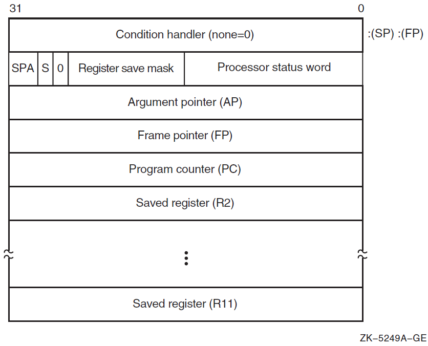
The contents of the stack located at addresses following the call frame belong to the calling program; they should not be read or written by the called procedure, except as specified in the argument list. The contents of the stack located at addresses lower than the call frame (at FP) belong to interrupt and exception routines; they are modified continually and unpredictably.
The called procedure allocates local storage by subtracting the required number of bytes from the stack provided on entry. This local storage is freed automatically by the RET instruction.
2.2.1.1. Calling Sequence
     CALLG    arglst, procedure
CALLS argcnt, procedureargcnt onto the stack
as along word and sets the argument pointer, AP, to the top of the stack. The
complete sequence using CALLS
follows: push argn
.
.
.
push arg1
CALLS #n, procedure2.2.1.2. Call Frames on Return
If the called procedure returns control to the calling procedure, control must return to the instruction immediately following the CALLG or CALLS instruction. Skip returns and GOTO returns are allowed only during stack unwind operations.
The called procedure returns control to the calling procedure by executing the return instruction (RET).
Note that when a routine completes execution, the system uses the FP in the call frame of the current procedure to locate the frame of the previous procedure. The system then removes the stack frame of the current procedure from the stack.
2.2.2. Stack Procedure Usage for OpenVMS Alpha
Fixed-size
Variable-size
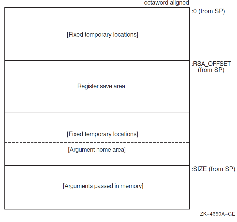
2.2.2.1. Fixed-Size Stack Frame
Figure 2.2, ''Fixed-Size Stack Frame Format'' illustrates the format of the stack frame for a procedure with a fixed amount of stack. The SP register is the stack base pointer for a fixed-size stack. In this case, R29 (FP) typically contains the address of the procedure descriptor for the current procedure.
The optional parts of the stack frame are created only as required by the particular procedure. As shown in Figure 2.2, ''Fixed-Size Stack Frame Format'', the field names within brackets are optional fields. The fixed temporary locations are optional sections of any stack frame that contain language-specific locations required by the procedure context of some high-level languages.
The register save area is a set of consecutive quadwords in which registers that are saved and restored by the current procedure are stored. The register save area (RSA) begins at the location pointed to by the RSA offset. The contents of the return address register (R26) are always saved in the first register field (SAVED_RETURN) of the register save area.
Use of the arguments passed in memory appending the end of the frame is described in Section 2.4.2, ''Argument Lists on OpenVMS Alpha''. For more detail concerning the fixed-size stack frame, see the VSI OpenVMS Calling Standard.
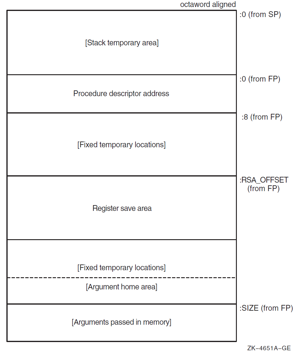
2.2.2.2. Variable-Size Stack Frame
Figure 2.3, ''Variable-Size Stack Frame Format'' illustrates the format of the stack frame for procedures with a varying amount of stack when PDSC$V_BASE_REG_IS_FP is 1. In this case, R29 (FP) contains the address that points to the base of the stack frame on the stack. This frame-base quadword location contains the address of the current procedure's descriptor.
The optional parts of the stack frame are created as required by the particular procedure. As shown in Figure 2.3, ''Variable-Size Stack Frame Format'', field names within brackets are optional fields. The fixed temporary locations are optional sections of any stack frame that contain language-specific locations required by the procedure context of some high-level languages.
A compiler can use the stack temporary area pointed to by the SP base register for fixed local variables, such as constant-sized data items and program state, as well as for dynamically sized local variables. The stack temporary area may also be used for dynamically sized items with a limited lifetime, for example, a dynamically sized function result or string concatenation that cannot be directly stored in a target variable. When a procedure uses this area, the compiler must keep track of its base and reset SP to the base to reclaim storage used by temporaries.
The register save area is a set of consecutive quadwords in which registers saved and restored by the current procedure are stored. The register save area (RSA) begins at the location pointed to by the offset PDSC$W_RSA_OFFSET. The contents of the return address register (R26) is always saved in the first register field (SAVED_RETURN) of the register save area.
Use of the arguments passed in memory appending the end of the frame is described in Section 2.4.2, ''Argument Lists on OpenVMS Alpha''. For more detail concerning the variable-size stack frame, see the VSI OpenVMS Calling Standard.
2.2.3. Stack Procedure Usage for OpenVMS IA-64
The I64 general registers are organized as a logically infinite set of stack frames that are allocated from a finite pool of physical registers.
Registers R0 through R31 are called global or static registers and are not part of the stacked registers. The stacked registers are numbered R32 up to a user-configurable maximum of R127. A called procedure specifies the size of its new stack frame using the alloc instruction. The procedure can use this instruction to allocate up to 96 registers per frame shared among input, output, and local values. When a call is made, the output registers of the calling procedure are overlapped with the input registers of the called procedure, thereby allowing parameters to be passed with no register copying or spilling. The hardware renames physical registers so that the stacked registers are always referenced in a procedure starting at R32.
Management of the register stack is handled by a hardware mechanism called the Register Stack Engine (RSE). The RSE moves the contents of physical registers between the general register file and memory without explicit program intervention. This provides a programming model that looks like an unlimited physical register stack to compilers; however, saving and restoring of registers by the RSE may be costly, so compilers should still attempt to minimize register usage.
2.2.3.1. Procedure Types
Memory stack procedure—allocates a memory stack and may maintain part or all of its caller's context on that stack.
Register stack procedure—allocates only a register stack and maintains its caller's context in registers.
- Null frame procedure—allocates neither a memory stack nor a register stack and therefore preserves no context of its caller.
Note
Unlike an Alpha null frame procedure (see the VSI OpenVMS Calling Standard), an I64 null frame procedure does not execute in the context of its caller because the I64 call instruction (br.call) changes the register set so that only the caller's output registers are accessible in the called routine. The caller's input and local registers cannot be accessed at all. The call instruction also changes the previous frame state (PFS) of the I64 processor.
A compiler may choose which type of procedure to generate based on the requirements of the procedure in question. A calling procedure does not need to know what type of procedure it is calling.
Every memory stack procedure or register stack procedure must have an associated unwind description (see the VSI OpenVMS Calling Standard) that describes what type of procedure it is and other procedure characteristics. A null frame procedure may also have an associated unwind description. (If not, a default description applies). This data structure is used to interpret the call stack at any given point in a thread's execution. It is typically built at compile time and usually is not accessed at run time except to support exception processing or other rarely executed code.
Read access to unwind descriptions is provided through the procedural interfaces described in the VSI OpenVMS Calling Standard.
To make invocations of that procedure visible to and interpretable by facilities such as the debugger, exception-handling system, and the unwinder.
To ensure that the context of the caller saved by the called procedure can be restored if an unwind occurs. (For a description of unwinding, see the VSI OpenVMS Calling Standard).
2.2.3.2. Memory Stack
The memory stack is used for local dynamic storage, spilled registers, and parameter passing. It is organized as a stack of procedure frames, beginning with the main program's frame at the base of the stack, and continuing towards the top of the stack with nested procedure calls. At the top of the stack is the frame for the currently active procedure. (There may be some system-dependent frames at the base of the stack, prior to the main program's frame, but an application program may not make any assumptions about them).
The memory stack begins at an address determined by the operating system, and grows towards lower addresses in memory. The stack pointer register (SP) always points to the lowest address in the current, topmost frame on the stack.
Each procedure creates its frame on entry by subtracting its frame size from the stack pointer, and removes its frame from the stack on exit by restoring the previous value of SP (usually by adding its frame size, but a procedure may save the original value of SP when its frame size varies).
Because the register stack is also used for the same purposes as the memory stack, not all procedures need a memory stack frame. However, every nonleaf procedure must save at least its return link and the previous frame marker, either on the register stack or on the memory stack. This ensures that there is an invocation context for every nonleaf procedure on one or both of the stacks.
2.2.3.3. Procedure Frames
A memory stack procedure frame consists of five regions, as illustrated in Figure 2.4, ''Procedure Frame''.
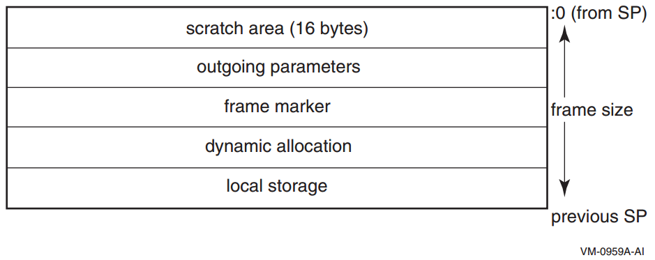
Scratch area. This 16-byte region is provided as scratch storage for procedures that are called by the current procedure. Leaf procedures need not allocate this region. A procedure may use the 16 bytes pointed to by the stack pointer (SP) as scratch memory, but the contents of this area are not preserved by a procedure call.
Outgoing parameters. Parameters in excess of those passed in registers are stored in this region of the stack frame. A procedure accesses its incoming parameters in the outgoing parameter region of its caller's stack frame.
Frame marker (optional). This region may contain information required for unwinding through the stack (for example, a copy of the previous stack pointer).
Dynamic allocation. This variable-sized region (initially zero length) can be created as needed.
Local storage. A procedure can store local variables, temporaries, and spilled registers in this region. For conventions affecting the layout of this area for spilled registers, see the VSI OpenVMS Calling Standard.
Note
A stack pointer that is not octaword aligned is valid only in a variable-sized frame because the unwind descriptor (MEM_STACK_F, see the VSI OpenVMS Calling Standard) for a fixed-size frame specifies the size in 16-byte units.
An application may not write to memory addresses lower than the stack pointer, because this memory area may be written to asynchronously (for example, as a result of exception processing).
Most procedures are expected to have a fixed-size frame, and the conventions are biased in favor of this. A procedure with a fixed-size frame may reference all regions of the frame with a compile-time constant offset relative to the stack pointer. Compilers should determine the total size required for each region, and pad the local storage area to make the total frame size a multiple of 16 bytes. The procedure can then create the frame by subtracting an immediate constant from the stack pointer in the prologue, and remove the frame by adding the same immediate constant to the stack pointer in the epilogue.
If a procedure has a variable-size frame (for example, a C routine that calls the alloca builtin), it should make a copy of SP to serve as a frame pointer before subtracting the initial frame size from the stack pointer. The procedure can then restore the previous value of the stack pointer in the epilogue without regard for how much dynamic storage has been allocated within the frame. It can also use the frame pointer to access the local storage region, because offsets from SP will vary.
The procedure uses an equivalent method of addressing the local storage region correctly before and after dynamic allocation.
The code satisfies the conditions imposed by the stack unwind mechanism.
To expand a stack frame dynamically, the scratch area, outgoing parameters, and frame marker regions (which are always located relative to the current stack pointer), must be relocated to the new top of stack. If the scratch area and outgoing parameter area are both clear of any live values, there is no actual work involved in relocating these areas. For procedures with dynamically sized frames, it is recommended that the previous stack pointer value be stored in a local stacked general register instead of the frame marker, so that the frame marker is also empty. If the previous stack pointer is stored in the frame marker, the code must take care to ensure that the stack is always unwindable while the stack is being expanded (see the VSI OpenVMS Calling Standard).
Other issues depend on the compiler and the code being compiled. The standard calling sequence does not define a maximum stack frame size, nor does it restrict how a language system uses any stack frame region beyond those purposes described here. For example, the outgoing parameter region can be used as scratch storage whenever it is not needed for passing parameters.
2.2.3.4. Register Stack
General registers R32 through R127 form a register stack that is automatically managed across procedure calls and returns. Each procedure frame on the register stack is divided into two dynamically sized regions: one for input parameters and local variables, and one for output parameters.
On a procedure call, the registers are automatically renamed by the hardware so that the caller's output registers form the base of the register stack frame of the callee. On return, the registers are restored to the previous state, so that the input and local registers are preserved across the call.
The ALLOC instruction is used at the beginning of a procedure to allocate the input, local, and output regions; the sizes of these regions are supplied as immediate operands. A procedure is not required to issue an ALLOC instruction if it does not need to store any values in its register stack frame. It may write to the first N stacked registers, where N is the value of the argument count passed in the argument information (AI) register (see Section 2.4.3.3, ''Argument Information (AI) Register''). It may not write to any other stack register without first issuing an ALLOC instruction.
ALLOC R36=rspfs, 4, 6, 5, 0
The actual registers to which the stacking registers are physically mapped are not directly addressable by the application software.
2.2.3.4.1. Input and Local Registers
The hardware makes no distinction between input and local registers. The caller's output registers automatically become the callee's register stack frame on a procedure call, with all registers initially allocated as output registers. An ALLOC instruction may increase or decrease the total size of the register stack frame, and may adjust the boundary between the input and local region and the output region.
The software conventions specify that up to eight general registers are used for parameter passing. Any registers in the input and local region beyond those eight may be allocated for use as preserved locals. Floating-point parameters may produce holes in the parameter list that is passed in the general registers; those unused input registers may also be used for preserved locals.
The caller's output registers do not need to be preserved for the caller. Once an input parameter is no longer needed, or has been copied elsewhere, that register may be reused for any other purpose within the procedure.
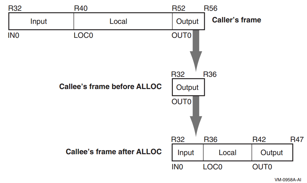
2.2.3.4.2. Output Registers
Up to eight output registers are used for passing parameters. If a procedure call requires fewer than eight general registers for its parameters, the calling procedure does not need to allocate more than are needed. If the called procedure expects more parameters, it will allocate extra input registers; these registers will be uninitialized.
A procedure may also allocate more than eight registers in the output region. While the extra registers may not be used for passing parameters, they can be used as extra scratch registers. On a procedure call, they will show up in the called procedure's output area as excess registers, and may be modified by that procedure. The called procedure may also allocate few enough total registers in its stack frame that the top of the called procedure's frame is lower than the caller's top-of-frame, but those registers will become available again when control returns to the caller.
2.2.3.4.3. Rotating Registers
A subset of the registers in the procedure frame may be designated as rotating registers. The rotating register region always starts with R32, and may be any multiple of eight registers in number, up to a maximum of 96 rotating registers. The renaming is under control of the Register Rename Base (RRB).
If the rotating registers include any or all of the output registers, software must be careful when using the output registers for passing parameters, because a non-zero RRB will change the virtual register numbers that are part of the output region. In general, software should ensure either that the rotating region does not overlap the output region, or that the RRB is cleared to zero before setting output parameter registers.
2.2.3.4.4. Frame Markers
The current application-visible state of the register stack is stored in an architecturally inaccessible register called the current frame marker. On a procedure call, this register is automatically saved by copying it to an application register, the previous function state (AR.PFS). The current frame marker is modified to describe a new stack frame whose input and local area is initially zero size, and whose output area is equal in size to the previous output area. On return, the previous frame state register is used to restore the current frame marker to its earlier value, and the base of the register stack is adjusted accordingly.
It is the responsibility of a procedure to save the previous function state register before issuing any procedure calls of its own, and to restore it before returning.
2.2.3.4.5. Backing Store for Register Stack
When the depth of the procedure call stack exceeds the capacity of the physical register file, the hardware frees physical registers by saving them into a memory stack. This backing store is distinct from the memory stack described in Section 2.2.3.2, ''Memory Stack''.
As returns unwind the procedure call stack, the hardware also restores previously-saved physical registers from the backing store.
The operation of this register stack engine (RSE) is mostly transparent to application software. While the RSE is running, application software may not examine the contents of the backing store, and may not make any assumptions about how much of the register stack is still in physical registers or in the backing store. In order to examine previous stack frames, application software must synchronize the RSE with the FLUSHRS instruction. Synchronizing the RSE forces all stack frames up to, but not including, the current frame to be saved in backing store, allowing the software to examine the contents of the backing store without asynchronous operations modifying the memory. Modifications to the backing store require setting the RSE to enforced lazy mode after synchronizing it, which prevents the RSE from doing any operations other than those required by calls and returns. The procedure for synchronizing the RSE and setting the mode is described in the Itanium® Software Conventions and Runtime Architecture Guide.
The backing store grows towards higher addresses. The top of the stack, which corresponds to the top of the previous procedure frame, is available in the Backing Store Pointer (BSP) application register. The BSP must always point to a valid backing store address, because the operating system may need to start the RSE to process an exception.
Backing store overflow is automatically detected by the OpenVMS operating system, which will either extend the backing store to allow continued operation or will raise an exception. Unlike for the memory stack (see Section 2.2.3.2, ''Memory Stack''), there are no specific rules or requirements that must be satisfied to facilitate detection of backing store overflow.
A NaT collection register is stored into the backing store following each group of 63 physical registers. The NaT bit of each register stored is shifted into the collection register. When the BSP reaches the quadword just before a 64-quadword boundary, the RSE stores the collection register. Software can determine the position of the NaT collection registers in the backing store by examining the memory address. This process is described in greater detail in the Itanium® Software Conventions and Runtime Architecture Guide.
2.2.4. Stack Procedure Usage for OpenVMS x86-64
Variable-size stack procedure (sometimes known as a normal procedure in industry x86-64 documentation)—allocates a memory stack that is addressable using either
%rbp(the frame pointer register) or%rsp(the stack pointer register). The size of the stack may vary during the procedure execution. The called procedure may maintain a part or the whole context of its caller on that stack.Fixed-size stack procedure (sometimes known as a framepointerless procedure in industry x86-64 documentation)—allocates a memory stack that is addressable only using
%rsp(the stack pointer register). The size of the stack is fixed during the procedure execution. The called procedure may maintain a part or the whole context of its caller on that stack.Null frame procedure (sometimes known as a frameless procedure in industry x86-64 documentation)—allocates no memory stack (other than the implicit saving of the caller return address that is a part of the CALL instruction). No context of its caller is saved.
All types of procedures allow use of 128 bytes of temporary storage below the address given in the stack pointer. This so-called red zone is not preserved across procedure calls, but is preserved by signal and condition handlers. Outside of the kernel, procedures may use this for temporary storage. Because hardware interrupts do not preserve the red zone, kernel code cannot use it. The use of the red zone can be disabled with a compiler option or pragma.
The red zone is useful in frameless leaf procedures (that call no other procedures). It gives them 128 bytes of scratch storage without the performance overhead of setting up and taking down a stack frame.
A compiler chooses which type of procedure to generate based on the requirements of the procedure in question. A calling procedure does not need to know what type of procedure it is calling.
Every variable-size stack or fixed-size stack procedure must have an associated unwind description (see the VSI OpenVMS Calling Standard) that provides information on the procedure type and its characteristics. A null frame procedure may also have an associated unwind description. (The default description applies if there is no unwind description). This data structure is used to interpret the call stack at any given point in a thread execution. It is built at compile time and usually is not accessed at run-time except to support exception processing or other rarely executed code.
2.2.4.1. Variable-Size Stack Procedures
Variable-size stack procedures allocate the stack that grows towards lower
addresses. The stack pointer (SP) is contained in the %rsp
register. The frame pointer (FP) is contained in the %rbp
register. The stack pointer is normally 0mod16 aligned and must be 0mod16
aligned when making a call. Because the return address is pushed on the stack by
the caller, the stack pointer is 8mod16 aligned on entry to a procedure. The
%rbp register is saved immediately below the return
address. The frame pointer points to the saved %rbp.
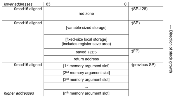
2.2.4.2. Fixed-Size Stack Procedures
Fixed-size stack procedures allocate the stack that grows towards lower
addresses. The stack pointer (SP) is contained in the %rsp
register. No frame pointer (FP) is used, so that the %rbp
register is available as an additional preserved register. The stack pointer is
normally 0mod16 aligned and must be 0mod16 aligned when making a call. Because
the return address is pushed on the stack by the caller, the stack pointer is
8mod16 aligned on entry to a procedure.
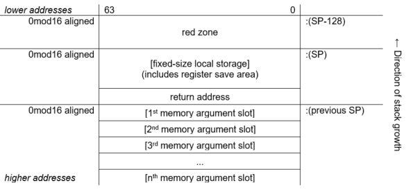
2.2.4.3. Null Frame Procedures
A null frame procedure is almost a special case of a fixed-size stack procedure. It is like a fixed-size stack which has no local storage other than the return address that is pushed on the stack as a result of the call. Because no additional stack is allocated it is unlike a fixed-size stack in that the alignment of the stack pointer is 8mod16 (not 0mod16).
A null frame procedure is necessarily a leaf procedure because the stack pointer must be 0mod16 aligned in order to make a call.
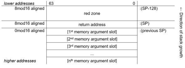
2.3. Procedure Representation
A procedure value is an address value that represents a procedure.
2.3.1. Procedure Values on OpenVMS VAX
On OpenVMS VAX systems, a procedure value is the address of the procedure entry mask that begins the actual code sequence of the procedure.
2.3.2. Procedure Values on OpenVMS Alpha
On OpenVMS Alpha systems, a procedure value in R27 is the address of the procedure descriptor that describes that procedure. So any OpenVMS Alpha procedure can be invoked by calling the stored address at offset 8 from the procedure descriptor (PDSC) starting address (procedure value).
2.3.3. Procedure Values on OpenVMS IA-64
On OpenVMS IA-64 systems, a procedure value is the address of a function descriptor, which consists of at least two quadword fields: the address of the entry point and the GP value required by that procedure.
Every procedure whose address is taken, or might be taken, must have a unique official function descriptor. The address of this function descriptor is used for the procedure value that is passed as a parameter or when two procedure values are compared. For other purposes, additional local function descriptors may be used for efficiency (notably in images other than the image that contains the procedure).
An official function descriptor for any procedure which might be callable from a VAX or Alpha translated image must include signature information. A local function descriptor used to call a procedure that might be part of a VAX or Alpha translated image must also include additional fields to facilitate the call. Both of these cases are described in the VSI OpenVMS Calling Standard.
A function descriptor for a bound procedure uses a special pseudo-GP value and includes an uplevel frame pointer. Such function descriptors are described in the VSI OpenVMS Calling Standard.
|
Kinds and Roles |
Size (Quadwords) |
|---|---|
|
Local function descriptor without translated image support | 2 |
|
Local function descriptor with translated image support (jacket function descriptor) | 4 |
|
Official function descriptor without translated image support | 3 |
|
Official function descriptor with translated image support | 3 |
|
Bound function descriptor | 6 |
Note that the different kinds of function descriptor are not self-identifying (that is, they do not contain any form of tag or kind field).
2.3.4. Procedure Values on OpenVMS x86-64
On OpenVMS x86-64 systems, a procedure value (a function pointer) is a pointer to code. To call through a procedure value, call through the value itself, not through a location in the memory pointed to by the value.
All procedure values must be representable in 32 bits. Because 32-bit addresses and pointers are always sign-extended before use, this means that the code they point to must reside in either the (hexadecimal) range 0..00000000 7FFFFFFF or FFFFFFFF 80000000..FFFFFFFF FFFFFFFF (see the VSI OpenVMS Programming Concepts Manual, Volume I for discussion of the structure of the OpenVMS address space). If the code is not in either of these regions, the linker creates a 32-bit-addressable trampoline for it. The trampoline code simply jumps to the procedure. The address of this trampoline becomes the value for that procedure.
Unbound procedures normally do not require an associated trampoline. They need a trampoline only if code in the same image takes the address of the procedure, or if it is a universal symbol.
Bound procedure values always point to trampolines. These trampolines are created by the containing procedure at the time it is called. When the bound procedure value trampolines pass control to the procedure, they pass an environment pointer (a pointer to the containing procedure stack frame) as an additional hidden parameter to the procedure.
2.4. Argument List
The calling standard defines a data structure called the argument list. An argument list is a sequence of locations in memory that represents a routine parameter list and possibly includes a function value. You use an argument list to pass information to a routine and receive results.
2.4.1. Argument Lists on OpenVMS VAX
On OpenVMS VAX systems, the first longword in an argument list (see Figure 2.9, ''Structure of a VAX Argument List'') stores the number of arguments (the argument count, n) as an unsigned integer value. The maximum argument count is 255. The remaining 24 bits of the first longword are reserved for OpenVMS and must be 0.
Both integer and floating-point values can be an argument passed in the argument list. Note that a 64-bit floating-point argument counts as 2 longword arguments in the list.
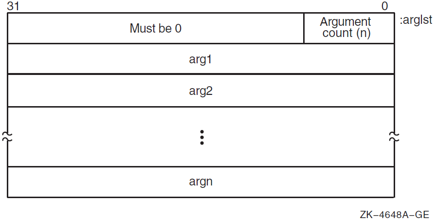
2.4.2. Argument Lists on OpenVMS Alpha
On OpenVMS Alpha systems, arguments are quadwords, and the calling program passes arguments in an argument item sequence. Each quadword in the sequence specifies a single argument. The argument item sequence is formed using R16—21 or F16—21 (a register for each argument). The argument item sequence can have a mix of integer and floating-point items that use both register types but must not repeat the same number. For example, an argument list might use R16, R17, F18, and R19. If there are more than six arguments, the argument items overflow to the end of the stack, as shown in Figure 2.10, ''Alpha Argument List Format''.
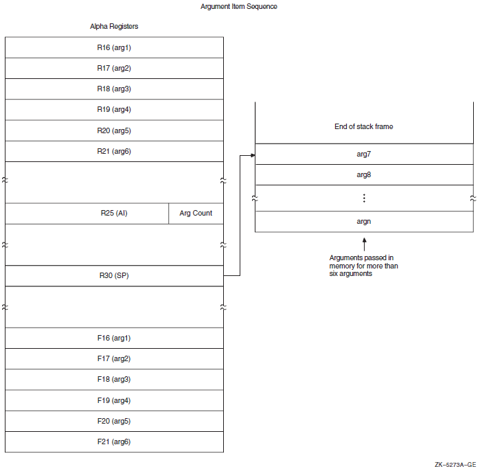
The calling procedure must pass to the called procedure information about the argument list. For high-level languages, this is performed by the language processor. In the argument information (AI) register (R25), the quadword format is the structure shown in Figure 2.11, ''Argument Information (AI) Register (R25) Format''. The AI register contains the argument count in the first byte. Table 2.15, ''Contents of the Argument Information Register (R25)'' describes the argument information fields in detail.
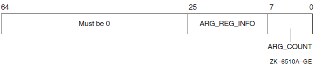
|
Field Name |
Contents | ||
|---|---|---|---|
|
AI$B_ARG_COUNT |
Unsigned byte <7:0> that specifies the number of 64-bit argument items in the argument list (known as the "argument count"). | ||
|
AI$V_ARG_REG_ |
An 18-bit vector field <25:8> divided into six groups of 3 bits that correspond to the six arguments passed in registers. These groups describe how each of the first six arguments are passed in registers with the first group <10:8> describing the first argument. The encoding for each group for the argument register usage follows: | ||
|
Value |
Name |
Meaning | |
| 0 |
AI$K_AR_I64 |
64-bit or 32-bit sign-extended to 64-bit argument passed in an integer register (including addresses). or Argument is not present. | |
| 1 |
AI$K_AR_FF |
F_floating argument passed in a floating register. | |
| 2 |
AI$K_AR_FD |
D_floating argument passed in a floating register. | |
| 3 |
AI$K_AR_FG |
G_floating argument passed in a floating register. | |
| 4 |
AI$K_AR_FS |
S_floating argument passed in a floating register. | |
| 5 |
AI$K_AR_FT |
T_floating argument passed in a floating register. | |
|
6, 7 | — |
Reserved. | |
|
Bits 26—63 |
Reserved and must be 0. | ||
2.4.3. Argument Lists on OpenVMS IA-64
On OpenVMS IA-64 systems, parameters are passed in a combination of general registers, floating-point registers, and memory, as illustrated in Figure 2.12, ''Parameter Passing in Registers and Memory''.
The parameter list is formed by placing each individual parameter into fixed-size elements of the parameter list, referred to as parameter slots. Each parameter slot is 64 bits wide; parameters larger than 64 bits are placed in as many consecutive parameter slots as are needed to contain the entire parameter. The rules for allocation and alignment of parameter slots are described in Section 2.4.3.1, ''Allocation of Parameter Slots''.
The contents of the first eight parameter slots are always passed in registers, while the remaining parameters are always passed on the memory stack, beginning at the caller's stack pointer plus 16 bytes. The caller uses up to eight of the registers in the output region of its register stack for integer and VAX floating-point parameters, and up to eight floating-point registers for IEEE floating-point parameters. The maximum number of registers used is eight.
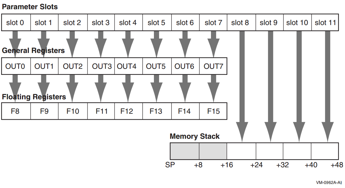
To accommodate variable argument lists in the C language, there is a fixed correspondence between parameter slots; the first parameter slot is always in either the first general output register or the first floating-point register (never both), the second parameter slot is always in the second general output register or the second floating-point register (never both), and so on. This allows a procedure to spill its register parameters easily to memory to form the argument home area before stepping through the parameter list with a pointer. The Argument Information register (AI) makes this possible, as explained in Section 2.4.3.3, ''Argument Information (AI) Register''.
A procedure can assume that the NaT bits on its incoming general register arguments are clear, and that the incoming floating-point register arguments are not NaTVals. A procedure making a call must ensure only that registers containing actual parameters are clear of NaT bits or NaTVals; registers not used for actual parameters are undefined.
The parameter passing mechanisms for I64 are generally the same as for Alpha and are included here for completeness. Two notable difference between Alpha and I64 are that the first six parameter slots are passed in registers for Alpha, while for I64 the first eight parameter slots are passed in registers; and that I64 passes VAX floating-point parameters in general registers.
2.4.3.1. Allocation of Parameter Slots
|
Type |
Size (Bits) |
Number of Slots |
|---|---|---|
|
Integer, small set |
1-64 |
1 |
|
Address/pointer (including all types passed by reference or descriptor) |
64 |
1 |
|
IEEE single-precision floating-point (S_floating) |
32 |
1 |
|
IEEE single-precision floating-point complex (S_floating) |
64 |
2 |
|
IEEE double-precision floating-point (T_floating) |
64 |
1 |
|
IEEE double-precision floating-point complex (T_floating) |
128 |
2 |
|
IEEE quad-precision floating-point (X_floating) |
64 (by reference) |
1 |
|
IEEE quad-precision floating-point complex (X_floating) |
64 (by reference) |
1 |
|
Aggregates (noncomplex) |
any |
(size+63)/64 |
|
VAX single-precision floating-point (F_floating) |
32 |
1 |
|
VAX single-precision floating-point complex (F_floating) |
64 |
2 |
|
VAX double-precision floating-point (D_ & G_floating) |
64 |
1 |
|
VAX double-precision floating-point complex (D_ & G_floating) |
128 |
2 |
Note
These rules are applied based on the type of the parameter after any type-promotion rules specified by the language have been applied. For example, a short integer passed without a function prototype in C is promoted to the int type, and is then passed according to the rules for the int type.
OpenVMS does not support passing the I64 double-precision extended
floating-point type (__float80), although that type may be
used from time to time in code generation sequences.
This placement policy does not ensure that parameters greater than 64 bits in size will fall on a natural alignment boundary if passed in memory. Such parameters may need to be copied by the called procedure into an aligned temporary prior to use, or accessed in a way that does not depend on natural alignment.
2.4.3.2. Normal Register Parameters
These eight argument slots are associated, one-to-one, with the stacked output general registers, as shown in Figure 2.12, ''Parameter Passing in Registers and Memory''.
Integral scalar parameters, (including addresses and pointers), VAX floating-point parameters, and aggregate parameters in these slots are passed only in the corresponding output general registers.
Aggregate parameters in these slots are passed by value only in the corresponding output general registers. The aggregate is treated as a sequence of 64-bit integral values, with each value allocated into the next available slot in aggregate memory address order. If the size of the aggregate is not an even multiple of 64 bits, then the unused bits in the last slot are undefined.
If an aggregate or VAX floating-point complex parameter straddles the boundary between slot 7 and slot 8, the part that lies within the first eight slots is passed in general registers, and the remainder is passed in memory, as described in Table 2.17, ''Unused Bits in Passed Data''.
Complex values (other than IEEE quad-precision floating-point complex), in those languages that include complex types, are passed as a pair of floating-point values (either single-precision or double-precision as appropriate). It is possible for the first of the two floating-point values in a complex value to occupy the last output register slot; in this case, the second floating-point value is passed in memory. IEEE quad-precision floating-point complex values are passed by reference.
IEEE single-precision and double-precision floating-point scalar parameters are passed in the corresponding floating-point register slot. IEEE quad-precision floating-point scalar parameters are passed by reference in the corresponding output general registers.
When IEEE floating-point parameters are passed in floating-point registers, they are passed in the register format, rounded to the appropriate precision. They are never passed in the general registers unless part of an aggregate, in which case they are passed in the aggregate memory format. When VAX floating-point parameters are passed in general registers, they are passed in memory format.
Parameters allocated beyond the eighth parameter slot are never passed in registers.
Note
Bit 31 is replicated in bits 32—63, even for unsigned 32-bit integers.
|
Data Type |
Type Designator? |
Data Size (bytes) |
Register Extension Type |
Memory Extension Type |
|---|---|---|---|---|
|
Byte logical |
DSC$K_DTYPE_BU |
1 |
Zero64 |
Zero64 |
|
Word logical |
DSC$K_DTYPE_WU |
2 |
Zero64 |
Zero64 |
|
Longword logical |
DSC$K_DTYPE_LU |
4 |
Sign64 |
Sign64 |
|
Quadword logical |
DSC$K_DTYPE_QU |
8 |
Data64 |
Data64 |
|
Byte integer |
DSC$K_DTYPE_B |
1 |
Sign64 |
Sign64 |
|
Word integer |
DSC$K_DTYPE_W |
2 |
Sign64 |
Sign64 |
|
Longword integer |
DSC$K_DTYPE_L |
4 |
Sign64 |
Sign64 |
|
Quadword integer |
DSC$K_DTYPE_Q |
8 |
Data64 |
Data64 |
|
F_floating |
DSC$K_DTYPE_F |
4 |
VAXF64 |
Data32 |
|
D_floating |
DSC$K_DTYPE_D |
8 |
VAXDG64 |
Data64 |
|
G_floating |
DSC$K_DTYPE_G |
8 |
VAXDG64 |
Data64 |
|
F_floating complex |
DSC$K_DTYPE_FC |
2 * 4 |
2*VAXF64 |
2*Data32 |
|
D_floating complex |
DSC$K_DTYPE_DC |
2 * 8 |
2*VAXDG64 |
2*Data64 |
|
G_floating complex |
DSC$K_DTYPE_GC |
2 * 8 |
2*VAXDG64 |
2*Data64 |
|
S_floating |
DSC$K_DTYPE_FS |
4 |
Hard |
Data32 |
|
T_floating |
DSC$K_DTYPE_FT |
8 |
Hard |
Data64 |
|
X_floating |
DSC$K_DTYPE_FX |
16 |
N/A |
N/A |
|
S_floating complex |
DSC$K_DTYPE_FSC |
2 * 4 |
2*Hard |
2*Data32 |
|
T_floating complex |
DSC$K_DTYPE_FTC |
2 * 8 |
2*Hard |
2*Data64 |
|
X_floating complex |
DSC$K_DTYPE_FXC |
2 * 16 |
N/A |
N/A |
|
Small structures of 8 bytes or less |
N/A |
≤8 |
Nostd |
Nostd |
|
Small arrays of 8 bytes or less |
N/A |
≤8 |
Nostd |
Nostd |
|
32-bit address |
N/A |
4 |
Sign64 |
Sign64 |
|
64-bit address |
N/A |
8 |
Data64 |
Data64 |
|
Sign Extension Type |
Defined Function |
|---|---|
|
Sign64 |
Sign-extended to 64 bits. |
|
Zero64 |
Zero-extended to 64 bits. |
|
Data32 |
Data is 32 bits. The state of bits <63:32> is unpredictable. |
|
2*Data32 |
Two single-precision parts of the complex value are stored in memory as independent floating-point values (each handled as Data32). |
|
Data64 |
Data is 64 bits. |
|
2*Data64 |
Two double-precision parts of the complex value are stored in memory as independent floating-point values (each handled as Data64). |
|
VAXF64 |
Data is 64 bits. Low-order 32 bits are the same as the F_floating memory format and the high-order 32 bits are zero. (Used only in a general register, never in a floating-point register). |
|
VAXDG64 |
Data is 64 bits. Uses the corresponding D_floating or G_floating memory format. (Used only in a general register, never in a floating-point register.) |
|
2*VAXF64 |
Two single-precision parts of the complex value are stored in memory as independent floating-point values (each handled as VAXF64). |
|
2*VAXDG64 |
Two double-precision parts of the complex value are stored in memory as independent floating-point values (each handled as VAXDG64). |
|
Hard |
Passed in the layout defined by the hardware SRM. |
|
2*Hard |
Two floating-point parts of the complex value are stored in a pair of registers as independent floating-point values (each handled as Hard). |
|
Nostd |
State of all high-order bits not occupied by the data is unpredictable across a call or return. |
2.4.3.3. Argument Information (AI) Register
In addition to the normal parameters, an implicit argument information value is passed in register R25, the Argument Information (AI) register. This value is shown in Figure 2.13, ''Argument Information Register Representation''. Note that I64 passes eight arguments in registers, while Alpha passes six arguments in registers.
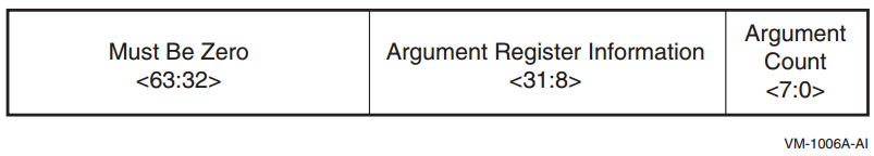
Argument Count is an unsigned byte that specifies the number of 64-bit argument slots used for the argument list. (Note that single- and double-precision complex values use two slots, which is reflected in this count).
|
Value |
OpenVMS Name |
Meaning |
|---|---|---|
|
0 |
AI$K_AR_I64 |
64-bit or 32-bit sign-extended to 64-bit argument passed in an integer register (including addresses). or Argument is not present. |
|
1 |
AI$K_AR_FF |
F_floating (also known as VAX single-precision floating-point) argument passed in a general register. |
|
2 |
AI$K_AR_FD |
D_floating (also known as VAX double-precision floating-point) argument passed in a general register. |
|
3 |
AI$K_AR_FG |
G_floating (also known as VAX double-precision floating-point) argument passed in a general register. |
|
4 |
AI$K_AR_FS |
S_floating (also known as IEEE single-precision floating-point) argument passed in a floating-point register. |
|
5 |
AI$K_AR_FT |
T_floating (also known as IEEE double-precision floating-point) argument passed in a floating-point register. |
|
6,7 |
— |
Reserved. |
2.4.3.4. Memory Stack Parameters
The remainder of the parameter list, beginning with slot 8, is passed in the outgoing parameter area of the memory stack frame, as described in the VSI OpenVMS Calling Standard. Parameters are mapped directly to memory, with slot 8 placed at location SP+16, slot 9 placed at location SP+24, and so on. Each argument is stored in memory as a series of one or more 64-bit storage units, with unused bits in the last unit undefined.
2.4.3.5. Variable Argument Lists
The rules above support variable-argument list functions in both the K&R and the ANSI dialects of the C language. (Note that argument location is independent of whether a prototype is in scope).
The nth argument is in either Rn or Fn regardless of the type of parameter in the preceding register slot. Therefore, a function with variable arguments may assume that the variable arguments that lie within the first eight argument slots can be found in either the stacked input integer registers (IN0-IN7), or in the floating-point parameter registers (F8-F15). Using the information codes from the AI (Argument Information) register (see Table 2.19, ''Argument Information Register Codes''), the function can then store these registers to memory using the 16-byte scratch area for IN6/F14 and IN7/F15, and up to 48 bytes at the base of its own stack frame for IN0/F8-IN5/F13, as necessary. This arrangement places all of the variable parameters in one contiguous block of memory.
2.4.3.6. Pointers to Formal Parameters
Whenever the address is formed of a formal parameter that is passed in a register, the compiler must store the parameter to the stack, as it would for a variable argument list.
2.4.3.6.1. Languages Other than C
The placement of arguments in general registers versus floating-point registers does not depend on any notion or concept of a prototype being in scope. It is therefore applicable to all languages at all times.
2.4.3.7. Rounding Floating-Point Values
There must be no difference in behavior between a floating-point parameter passed directly in a register and a floating-point parameter that has been stored to memory and reloaded. In either case, the floating-point value must be the same. This implies that floating-point parameters passed in floating-point registers must be explicitly rounded to the proper precision by the caller.
2.4.4. Argument Lists on OpenVMS x86-64
On OpenVMS x86-64 systems, procedure parameters are passed in registers and/or on the stack.
2.4.4.1. Scalar Argument Types
the six general-purpose registers (
%rdi,%rsi,%rdx,%rcx,%r8, and%r9)the eight XMM registers (
%xmm0—%xmm7)the stack.
|
Nominal Type | Argument Location | Return Value Location |
|---|---|---|
| Pointer [Q] |
The next available general-purpose register. Otherwise, in the next argument slot on the stack. | General-purpose register
%rax |
| Boolean [B, BU] | ||
| Integers (size ≤ 64 bits) [B, W, L, Q, BU, WU, LU, QU] | ||
| Integers (64 < size ≤ 128 bits) [O, OU] |
The next two available general-purpose registers. Otherwise, in the next two argument slots on the stack. | General-purpose registers %rax (low
half) and %rdx (high half) |
| VAX float (F_floating, D_floating, and G_floating) [F, D, G] |
The next available general-purpose register. Otherwise, in the next argument slot on the stack. | General-purpose register %rax |
| IEEE single-precision float (S_floating) [FS] |
Bits 31:0 of the next available XMM register. Otherwise, in the next argument slot on the stack. | Bits 31:0 of register %xmm0 |
| IEEE double-precision float (T_floating) [FT] |
Bits 63:0 of the next available XMM register. Otherwise, in the next argument slot on the stack. | Bits 63:0 of register %xmm0 |
| IEEE quadruple-precision float (X_floating) [FX] |
The next available XMM register. Otherwise, in the next two argument slots on the stack. | Register %xmm0 |
| VAX complex single-precision float (F_floating) [FC] |
The next available general-purpose register. Otherwise, in the next argument on the stack. |
General-purpose register
|
| VAX complex double-precision float (D_floating and G_floating) [DC, GC] |
The next two available general-purpose registers. Otherwise, in the next two argument slots on the stack. | Registers %rax (the real part of a
value) and %rdx (the imaginary part of a
value) |
| IEEE complex single-precision float [FSC] |
In the next available XMM register, real part in bits 31:0, imaginary part in bits 63:32. Otherwise, in the next argument slot on the stack. | Register %xmm0, the real part of a
value in bits 31:0, the imaginary part in bits 63:32 |
| IEEE complex double-precision float [FTC] |
In bits 63:0 of the next two available XMM registers. Otherwise, the next two argument slots on the stack. | Bits 63:0 of registers %xmm0 (the real
part of a value) and %xmm1 (the imaginary
part of a value) |
| IEEE complex quadruple-precision float [FXC] | In the next four available argument slots on the stack. | In a caller-allocated memory buffer whose address is passed as a hidden first argument |
An argument that requires two registers is never split so that the first part is in a register and the second part is on the stack. Either both parts are in registers or both parts are on the stack.
For example, a procedure that takes ten integer scalar arguments will find the first six arguments in the general-purpose registers, and the last four on the stack. A procedure that takes ten IEEE double-precision floating-point scalars as arguments will find the first eight arguments in the XMM registers, and the last two on the stack. And, a procedure that takes six integer arguments and eight floating-point arguments, regardless of how the integer and floating-point arguments are intermixed, will find all 14 arguments in registers.
2.4.4.2. Aggregate Argument Types
This section describes how the aggregate argument types are passed to procedures.
First, the argument types are assigned in the appropriate classes and then the registers are allocated for passing them.
INTEGER class consists of integral types that fit in one of the general-purpose registers including pointers.
SSE class consists of types that fit in a floating-point register.
SSEUP class consists of types that fit into a floating-point register and can be passed and returned in the upper bytes of it.
X87, X87UP, COMPLEX_X87 classes consist of types that can be returned via the x87 FPU.
NO_CLASS is used as initializer in the algorithms. It is used for padding as well as empty structures and unions.
MEMORY class consists of types that are passed and returned in memory via the stack.
The size of each argument is rounded up to a quadword (8 bytes). Therefore, the stack will always be 8-byte aligned.
|
Nominal Type | Equivalent C/C++ Type(s) | Argument Passing Class |
|---|---|---|
| Pointer [Q] | * | INTEGER |
| Boolean [B, BU] | _Bool (bool) | |
| Integers (size ≤ 64 bits) [B, W, L, Q, BU, WU, LU, QU] | char, short, int, long (signed and unsigned) | |
| Integers (64 < size ≤ 128 bits) [O, OU] | __int128 (signed and unsigned) | Split into two 8-byte chunks. Both belong to class INTEGER. |
| VAX floating-point types (up to 64 bits) [F, D, G] | INTEGER | |
| VAX floating-point complex (64 bits) [FC] | INTEGER | |
| VAX floating-point complex (128 bits) [DC, GC] | Split into two 8-byte chunks. Both belong to class INTEGER. | |
| IEEE binary floating-point types (up to 64 bits) [FS, FT] | float, double | SSE |
| IEEE extended binary floating-point type (128 bits) [FX] | __float128 | Split into two halves. The first (lower addressed) 64-bits belong to class SSE and the second half to class SSEUP. |
| IEEE binary floating-point complex (64 bits) [FSC] | complex float | Treat as two successive binary floating-point values, each treated as a scalar of half the size (see above). |
| IEEE binary floating-point complex (128 bits) [FTC] | complex double | |
| IEEE binary floating-point complex (256 bits) [FXC] | complex long double |
If the size of an object is larger than eight quadwords (64 bytes), or it contains unaligned fields, it belongs to the MEMORY class.
If a C++ object is non-trivial for the purpose of calls, as specified in the C++ ABI?, it is passed by an invisible reference—that is, the object is replaced in the parameter list by a pointer that has the INTEGER class.?
If the size of the aggregate exceeds a single quadword, each quadword is classified separately. Each quadword is initialized to the NO_CLASS class.
- Each field of an object is classified recursively so that always two fields are considered. The two fields are the containing quadword as a whole and the lowest level field components of the quadword, considered in order:
If both classes are equal, this is the resulting class.
If one of the classes is NO_CLASS, the resulting class is the other class.
If one of the classes is MEMORY, the result is the MEMORY class.
If one of the classes is INTEGER, the result is the INTEGER class.
If one of the classes is X87, X87UP, or COMPLEX_X87, the result is the MEMORY class.
Otherwise the result is the SSE class.
- Then a post merger cleanup is done:
If one of the classes is MEMORY, the whole argument is passed in memory.
If X87UP is not preceded by X87, the whole argument is passed in memory.
If the size of the aggregate exceeds two quadwords and the first quadword is not SSE or any other quadword is not SSEUP, the whole argument is passed in memory.
If SSEUP is not preceded by SSE or SSEUP, it is converted to SSE.
If the class is MEMORY, the argument is passed on the stack.
If the class is INTEGER, the next available register of the sequence
%rdi,%rsi,%rdx,%rcx,%r8, and%r9is used.If the class is SSE, the argument is passed in the next available floating-point register. The registers are taken in order from
%xmm0to%xmm7.If the class is SSEUP, the quadword is passed in the next available 8-byte chunk of the last used floating-point register.
If the class is X87, X87UP, or COMPLEX_X87, the argument is passed in memory.
When a value of a boolean type is returned or passed in a register or on the stack, bit 0 contains the truth value, bits 1 to 7 must be zero, and all other bits are left unspecified. A consumer of such values can rely on it being 0 or 1 only when truncated to the low byte.
If there are no registers available for any quadword of an argument, the whole argument is passed on the stack. If registers have already been assigned for some quadwords of such an argument, the assignments are reverted.
Once registers are assigned, the arguments passed in memory are pushed on the stack in reversed (right-to-left?) order.
|
Nominal Type | Equivalent C/C++ Type(s) | Argument Passing Class |
|---|---|---|
| IEEE binary floating-point vector (up to 64 bits) [M64] | __m64 | SSE |
| IEEE extended binary floating-point vector (128 bits) [M128] | __m128 | Split into two halves. The first (lower addressed) 64-bits belong to class SSE and the second half to class SSEUP. |
| IEEE binary floating-point vector (256 bits) [M256] | __m256 | Split into four 8-byte chunks. The first chunk belongs to class SSE and the rest to class SSEUP. |
| IEEE binary floating-point vector (512 bits) [M512] | __m512 | Split into eight 8-byte chunks. The first chunk belongs to class SSE and the rest to class SSEUP. |
When passing the __m256 or __m512
arguments to functions that use varargs or stdarg, function prototypes must be
provided. Otherwise, the run-time behavior is undefined.
2.4.4.3. Unused Bits in Passed Data
Note
Bit 31 is replicated in bits 32—63, even for unsigned 32-bit integers.
This rule applies to the argument types described in Section 2.4.4.1, ''Scalar Argument Types'' as well as the individual elements of aggregate types passed in general-purpose registers as described in Section 2.4.4.2, ''Aggregate Argument Types''.
|
Data Type |
Type Designator? |
Data Size (bytes) |
Register Extension Type |
Memory Extension Type |
|---|---|---|---|---|
|
Byte logical |
DSC$K_DTYPE_BU |
1 |
Zero64 |
Zero64 |
|
Word logical |
DSC$K_DTYPE_WU |
2 |
Zero64 |
Zero64 |
|
Longword logical |
DSC$K_DTYPE_LU |
4 |
Sign64 |
Sign64 |
|
Quadword logical |
DSC$K_DTYPE_QU |
8 |
Data64 |
Data64 |
|
Byte integer |
DSC$K_DTYPE_B |
1 |
Sign64 |
Sign64 |
|
Word integer |
DSC$K_DTYPE_W |
2 |
Sign64 |
Sign64 |
|
Longword integer |
DSC$K_DTYPE_L |
4 |
Sign64 |
Sign64 |
|
Quadword integer |
DSC$K_DTYPE_Q |
8 |
Data64 |
Data64 |
|
F_floating |
DSC$K_DTYPE_F |
4 |
VAXF64 |
Data32 |
|
D_floating |
DSC$K_DTYPE_D |
8 |
VAXDG64 |
Data64 |
|
G_floating |
DSC$K_DTYPE_G |
8 |
VAXDG64 |
Data64 |
|
F_floating complex |
DSC$K_DTYPE_FC |
2 * 4 |
2*VAXF64 |
2*Data32 |
|
D_floating complex |
DSC$K_DTYPE_DC |
2 * 8 |
2*VAXDG64 |
2*Data64 |
|
G_floating complex |
DSC$K_DTYPE_GC |
2 * 8 |
2*VAXDG64 |
2*Data64 |
|
S_floating |
DSC$K_DTYPE_FS |
4 |
Hard |
Data32 |
|
T_floating |
DSC$K_DTYPE_FT |
8 |
Hard |
Data64 |
|
X_floating |
DSC$K_DTYPE_FX |
16 |
N/A |
N/A |
|
S_floating complex |
DSC$K_DTYPE_FSC |
2 * 4 | Hard? |
2*Data32 |
|
T_floating complex |
DSC$K_DTYPE_FTC |
2 * 8 |
2*Hard |
2*Data64 |
|
X_floating complex |
DSC$K_DTYPE_FXC |
2 * 16 |
N/A |
N/A |
|
Small structures of 8 bytes or less |
N/A |
≤8 |
Nostd |
Nostd |
|
Small arrays of 8 bytes or less |
N/A |
≤8 |
Nostd |
Nostd |
|
32-bit address |
N/A |
4 |
Sign64 |
Sign64 |
|
64-bit address |
N/A |
8 |
Data64 |
Data64 |
|
Sign Extension Type |
Defined Function |
|---|---|
|
Sign64 |
Sign-extended to 64 bits. |
|
Zero64 |
Zero-extended to 64 bits. |
|
Data32 |
Data is 32 bits. The state of bits <63:32> is unpredictable. |
|
2*Data32 |
Two single-precision parts of the complex value are stored in memory as independent floating-point values (each handled as Data32). |
|
Data64 |
Data is 64 bits. |
|
2*Data64 |
Two double-precision parts of the complex value are stored in memory as independent floating-point values (each handled as Data64). |
|
VAXF64 |
Data is 64 bits. Low-order 32 bits are the same as the F_floating memory format and the high-order 32 bits are zero. (Used only in a general register, never in a floating-point register). |
|
VAXDG64 |
Data is 64 bits. Uses the corresponding D_floating or G_floating memory format. (Used only in a general register, never in a floating-point register). |
|
2*VAXF64 |
Two single-precision parts of the complex value are stored in memory as independent floating-point values (each handled as VAXF64). |
|
2*VAXDG64 |
Two double-precision parts of the complex value are stored in memory as independent floating-point values (each handled as VAXDG64). |
|
Hard |
Passed in the layout defined by the hardware SRM. |
|
2*Hard |
Two floating-point parts of the complex value are stored in a pair of registers as independent floating-point values (each handled as Hard). |
|
Nostd |
State of all high-order bits not occupied by the data is unpredictable across a call or return. |
2.4.4.4. Argument Information Register (AI)
%rax is used as the AI register. It must
contain the argument information that is presented in Table 2.25, ''Contents of the Argument Information Register
(%rax)''.%rax)| Bit | Contents |
|---|---|
7:0 (%al) | Upper bound on the number of XMM registers that are used to pass arguments |
15:8 (%ah) | Total number of passed argument slots |
| 47:16 | Argument Info Offset relative to the return address of the caller, or zero |
| 63:48 |
Reserved and must be either 0x0000 or 0xFFFF? |
If the Argument Info Offset field is non-zero, it contains a signed byte offset to an Argument Info Block (AIB). This byte offset is relative to the return address of the caller, that is, an offset from the location of the instruction after the call instruction. The Argument Info Block must be close enough to the call site for the offset to fit in 32 bits. If the AIB is in the same section as the code, this offset can be calculated at compile time.
| Bit | Name | Usage |
|---|---|---|
| 7:0 | version | Format version. This format is version 1. |
| 15:8 | arg info count | Number of argument slots represented in this block. |
| 19:16 | 1st arg info | Information on the 1st argument slot. |
| 23:20 | 2nd arg info | Information on the 2nd argument slot. |
|
. | ||
| Information on the nth argument slot. |
The arg info count may be less than, equal to, or greater than the actual number of passed arguments. If it is less, the missing argument information fields are assumed to be 0 (AI$K_AR_I64). If it is greater, the extra entries in this block are ignored.
If all the passed arguments are integers and pointers, there is no need to pass an Argument Info Block. Instead, the Argument Info Offset should be set to zero.
| Value | Name | Meaning |
|---|---|---|
| 0 | AI$K_AR_I64 |
Argument is passed in a general-purpose register, if one is available, otherwise on the stack. or Argument is not present. |
| 1 | AI$K_AR_FF | F_floating argument is passed in a general-purpose register. |
| 2 | AI$K_AR_FD | D_floating argument is passed in a general-purpose register. |
| 3 | AI$K_AR_FG | G_floating argument is passed in a general-purpose register. |
| 4 | AI$K_AR_FS | Argument is passed in bits 31:0 of an XMM register. |
| 5 | AI$K_AR_FT | Argument is passed in bits 63:0 of an XMM register. |
| 6 | AI$K_AR_FXL | Low half of argument is passed in bits 63:0 of an XMM register. |
| 7 | AI$K_AR_FXH | High half of argument is passed in bits 127:64 of an XMM register. |
| 8 | AI$K_AR_MEM | Argument is pushed on the stack. |
| 9—15 | — | Reserved. |
2.4.4.5. Variable Argument Lists
The x86-64 industry standards define how C-style variable argument lists (va_start, va_arg and so on) are implemented. OpenVMS also allows variable argument lists to be accessed as arrays. On prior OpenVMS architectures, a single common mechanism supports both. On OpenVMS x86-64, different mechanisms are implemented.
2.4.4.5.1. Standard Variable Arguments
| Offset | Register | Usage |
|---|---|---|
| 0 | %rdi | 1st general-purpose argument register |
| 8 | %rsi | 2nd general-purpose argument register |
| 16 | %rdx | 3rd general-purpose argument register |
| 24 | %rcx | 4th general-purpose argument register |
| 32 | %r8 | 5th general-purpose argument register |
| 40 | %r9 | 6th general-purpose argument register |
| 48 | %xmm0 | 1st floating-point argument register |
| 64 | %xmm1 | 2nd floating-point argument register |
| 80 | %xmm2 | 3rd floating-point argument register |
| 96 | %xmm3 | 4th floating-point argument register |
| 112 | %xmm4 | 5th floating-point argument register |
| 128 | %xmm5 | 6th floating-point argument register |
| 144 | %xmm6 | 7th floating-point argument register |
| 160 | %xmm7 | 8th floating-point argument register |
The register save area is always allocated in the stack frame of the
called function. Any function that contains an invocation of the va_start
macro must save argument registers in the register save area. The six
general-purpose registers are always saved. The number of floating-point
registers to be saved depends on the value passed in the
%al register. In theory, code should not save more
registers than indicated in %al, but in practice, it
either saves none (if %al is zero) or all the
registers.
The standard requires the caller to pass a floating-point register
argument count in the %al register whenever the called
function uses the C variable arguments. This includes not only functions
explicitly declared with the variable arguments, but all unprototyped
functions as well.
Note that the OpenVMS “arginfo notused” linkage does not influence whether
this value is passed in the %al or not. The passed value
does not need to be absolutely correct, but should at least be an upper
bound on the number of arguments passed in floating-point registers.
| Offset | Field | Usage |
|---|---|---|
| 0 | gp_offset | Byte offset from the start of the register save area of the next available saved integer argument register |
| 4 | fp_offset | Byte offset from the start of the register save area of the next available saved floating-point argument register |
| 8 | overflow_arg_area | Pointer to the first available stack argument |
| 16 | reg_save_area | Pointer to the register save area |
gp_offset is the byte offset within the register save area of the first unused general-purpose register.
fp_offset is the byte offset within the register save area of the first unused floating-point register.
overflow_arg_area points to the first unused stack argument.
reg_save_area points to the register save area that is already initialized.
printf(const char *fmt, ...)
function, the va_list structure is initialized as follows:gp_offset is set to +8, the offset of the second general-purpose argument; the first argument (
fmt) is already used.fp_offset is set to +48, the offset of the first floating-point argument.
overflow_arg_area is set to FP+16, the location of the first stack argument.
When the va_arg macro is invoked, it fetches the argument from a saved register or the stack and increments one field on the va_list structure accordingly. For example, if an integer argument is requested, the va_arg macro will compare the value of gp_offset against 48. If gp_offset is less than 48, the va_arg macro will return a saved integer register and increment gp_offset. Otherwise, it will return a stack argument and increment overflow_arg_area.
2.4.4.5.2. OpenVMS Variable Argument Lists
ARGPTR, ACTUALPARAMETER and ACTUALCOUNT in BLISS
[list], argument, and argument_list_length in VSI Pascal
va_count in VSI C
All rely on OpenVMS extensions to the standard calling conventions.
On OpenVMS standard calls, the caller passes argument information in the
%rax register that specifies the total number of the
used argument slots and location of each register argument. In theory, this
information only needs to be passed if the called procedure uses one of the
above mentioned language constructs, but since the caller is not able to
determine this, the argument information is passed in
%rax on all OpenVMS standard calls. It can be
suppressed with the “arginfo notused” linkage specification.
%ah. If a called procedure requests an argument list,
the called procedure performs the following:Allocates the storage in its own stack frame for the entire arglist (8 *
%ah).Copies all general-purpose registers, floating-point registers, and memory arguments to the arglist as indicated by the values in
%rax.
Unlike the prior OpenVMS architectures, on OpenVMS x86-64 it is not possible to create a register “home” on the stack that is contiguous with the incoming memory arguments.
2.5. Argument Passing Mechanisms
Each high-level language supported by OpenVMS provides a mechanism for passing arguments to a procedure. The specifics of the mechanism and the terminology used, however, vary from one language to another. For specific information, refer to the appropriate high-level language user's guide.
arg1
through argn are the actual parameters, which can be any of the
following addresses or value:An uninterpreted 32-bit value on VAX or 64-bit value on Alpha and IA-64 systems is passed by value.
An address of a data value is passed by reference.
An address of a descriptor that contains a pointer to a data value is passed by descriptor (for example, a string might be the data value).
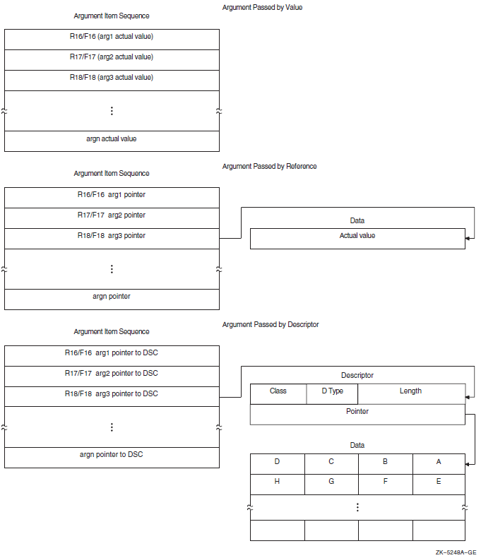
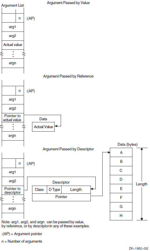
OpenVMS programming reference manuals provide a description of each OpenVMS system routine that indicates how each argument is to be passed. Phrases such as "an address" and "address of a character string descriptor" identify reference and descriptor arguments, respectively. Terms like "Boolean value," "number," "value," and "mask" indicate an argument that is passed by value.
2.5.1. Passing Arguments by Value
When your program passes an argument using the by value mechanism, the argument list entry contains either the actual uninterpreted 32-bit VAX value or a 64-bit Alpha or I64 value (zero- or sign-extended) of the argument. For example, to pass the constant 100 by value, the calling program puts 100 directly in the argument list or sequence. For more information about passing 64-bit Alpha and I64 values, refer to VSI OpenVMS Programming Concepts Manual, Volume I.
All high-level languages (except C) require you to specify the by-value mechanism explicitly when you call a procedure that accepts an argument by value. For example, FORTRAN uses the %VAL built-in function, while COBOL uses the BY VALUE qualifier on the CALL[USING] statement.
     INCLUDE  '($SSDEF)'
     CALL LIB$STOP (%VAL(SS$_INTOVF))
LIB$SIGNAL (SS$_INTOVF)
     PUSHL    #SS$_INTOVF        ; Push longword by value
     CALLS    #1,G^LIB$SIGNAL    ; Call LIB$SIGNAL
 #include <starlet.h>         /* Declare the function*/
       .
       .
     enum  cluster0
        {
           completion, breakdown, beginning
        }  event;

     int status;
     event = completion;
       .
       .
     status = sys$setef(event);     /* Set event flag */
2.5.2. Passing Arguments by Reference
When your program passes arguments using the by reference
mechanism, the argument list entry contains the address of the location that
contains the value of the argument. For example, if variable x is
allocated at location 1000, the argument list entry will contain 1000, the address
of the value of x.
On Alpha processors and I64, the address is sign-extended from 32 bits to 64 bits.
Most languages (but not C) pass scalar data by reference by default. Therefore, if
you simply specify x in the CALL statement or function
invocation, the language automatically passes the value stored at the location
allocated to x to the OpenVMS system routine.
LIB$FLT_UNDER (%REF(1))ONE: .LONG 1 ; Longword value 1
.
.
.
PUSHAL ONE ; Push address of longword
CALLS #1,G^LIB$FLT_UNDER ; Call LIB$FLT_UNDER/* This program shows how to call system service SYS$READEF. */ #include <ssdef.h> #include <stdio.h> #include <starlet.h> /* Declare the function */ main(void) { /* Longword that receives the status * * of the event flag cluster */ unsigned cluster_status; int return_status; /* Status: SYS$READEF */ /* Argument values for SYS$READEF */ enum cluster0 { completion, breakdown, beginning } event; . . . event = completion; /* Event flag in cluster 0 */ /* Obtain status of cluster 0. * * Pass value of event and * * address of cluster_status. */ return_status = SYS$READEF(event, &cluster_status); /* Check for successful call */ if (return_status != SS$WASCLR && return_status != SS$WASSSET) { /* Handle the error here. */ . . . } else { /* Check bits of interest in cluster_status here. */ . . . } }
2.5.3. Passing Arguments by Descriptor
When a procedure specifies that an argument is passed by descriptor, the argument list entry must contain the address of a descriptor for the argument. For more information about OpenVMS Alpha 64-bit descriptors, refer to VSI OpenVMS Programming Concepts Manual, Volume I.
On Alpha and I64 processors, the address is sign-extended from 32 bits to 64 bits.
|
Symbol |
Description |
|---|---|
|
DSC$W_LENGTH |
Length of data (or DSC$W_MAXSTRLEN, maximum length, for varying strings) |
|
DSC$B_DTYPE |
Data type |
|
DSC$B_CLASS |
Descriptor class code |
|
DSC$A_POINTER |
Address at which the data begins |
The VSI OpenVMS Calling Standard describes these fields in greater detail.
    100    COMMON STRING GREETING = 30
200 CALL LIB$PUT_SCREEN(GREETING) CALL LIB$PUT_OUTPUT USING BY DESCRIPTOR GREETINGMSGDSC: .WORD LEN ; DESCRIPTOR: DSC$W_LENGTH .BYTE DSC$K_DTYPE_T ; DSC$B_DTYPE .BYTE DSC$K_CLASS_S ; DSC$B_CLASS .ADDRESS MSG ; DSC$A_POINTER MSG: .ASCII/Hello/ ; String itself LEN = .-MSG ; Define the length of the string .ENTRY EX1,^M<> PUSHAQ MSGDSC ; Push address of descriptor CALLS #1,G^LIB$PUT_OUTPUT ; Output the string RET .END EX1
MODULE BLISS1 (MAIN = BLISS1,    ! Example of calling LIB$PUT_OUTPUT
        IDENT = '1-001',
        ADDRESSING_MODE(EXTERNAL = GENERAL)) =
BEGIN
EXTERNAL ROUTINE
    LIB$STOP,                   ! Stop execution via signaling
    LIB$PUT_OUTPUT;             ! Put a line to SYS$OUTPUT

FORWARD ROUTINE
    BLISS1 : NOVALUE;

LIBRARY 'SYS$LIBRARY:STARLET.L32';

ROUTINE BLISS1                  ! Routine
        : NOVALUE =

    BEGIN
!+
! Allocate the necessary local storage.
!-
    LOCAL
        STATUS,                         ! Return status
        MSG_DESC : BLOCK [8, BYTE];     ! Message descriptor

    BIND
        MSG = UPLIT('HELLO');

!+
! Initialize the string descriptor.
!-
    MSG_DESC [DSC$B_CLASS] = DSC$K_CLASS_S;
    MSG_DESC [DSC$B_DTYPE] = DSC$K_DTYPE_T;
    MSG_DESC [DSC$W_LENGTH] = 5;
    MSG_DESC [DSC$A_POINTER] = MSG;
!+
! Put out the string.  Test the return status.
! If it is not a success, then signal the RMS error.
!-
    STATUS = LIB$PUT_OUTPUT(MSG_DESC);
    IF NOT .STATUS THEN LIB$STOP(.STATUS);
    END;                ! End of routine BLISS1
END                     ! End of module BLISS1
ELUDOM
 /*  This program shows a call to system service SYS$SETPRN.  */

 #include <ssdef.h>
 #include <stdio.h>
                              /*  Define structures for descriptors  */
 #include <descrip.h>

 #include starlet.h           /*  Declare the function  */

 int main(void)
 {
   int  ret;                  /*  Define return status of SYS$SETPRN  */

   struct  dsc$descriptor_s  name_desc;  /* Name the descriptor */

   char  *name =  "NEWPROC";             /* Define new process name */
      .
      .
      .
   name_desc.dsc$w_length = strlen(name);  /* Length of name without *
                                            * null terminator        */

   name_desc.dsc$a_pointer =  name; /* Put address of shortened string *
                                     * in descriptor             */

   name_desc.dsc$b_class =  DSC$K_CLASS_S; /* String descriptor class */

   name_desc.dsc$b_dtype =  DSC$K_DTYPE_T; /* Data type: ASCII string */
      .
      .
      .
   ret =  sys$setprn(&name_desc);

   if (ret != SS$_NORMAL)                  /*  Test return status  */
      fprintf(stderr, "Failed to set process name\n"),
      exit(ret);
      .
      .
      .
 }
2.5.4. Passing Scalars as Arguments
When you are passing an input scalar value to an OpenVMS system routine, you usually pass it either by reference or by value. You usually pass output scalar arguments by reference to OpenVMS system routines. An output scalar argument is the address of a location where some scalar output of the routine will be stored.
2.5.5. Passing Arrays as Arguments
Arrays are passed to OpenVMS system routines by reference or by descriptor.
Sometimes the routine knows the length and dimensions of the array to be received, as in the case of the table passed to LIB$CRC_TABLE. Arrays such as this are normally passed by reference.
In other cases, the routine actually analyzes and operates on the input array. The routine does not necessarily know the length or dimensions of such an input array, so a descriptor is necessary to provide the information the routine needs to describe the array accurately.
2.5.6. Passing Strings as Arguments
|
Descriptor Function |
Descriptor Class Code |
Numeric Value |
|---|---|---|
|
Fixed length (string/scalar) |
DSC$K_CLASS_S |
1 |
|
Dynamic |
DSC$K_CLASS_D |
2 |
|
Array |
DSC$K_CLASS_A |
4 |
|
Scaled decimal |
DSC$K_CLASS_SD |
9 |
|
Noncontiguous array |
DSC$K_CLASS_NCA |
10 |
|
Varying length |
DSC$K_CLASS_VS |
11 |
Fixed length — Characterized by an address and a constant length
Varying length — Characterized by an address, a current length, and a maximum length
Dynamic — Characterized by a current address and a current length
2.6. Combinations of Descriptor Class and Data Type
Some combinations of descriptor class and data type are not permitted, either because they are not meaningful or because the calling standard does not recognize them. Possibly, the same function can be performed with more than one combination. This section describes the restrictions on the combinations of descriptor classes and data types. These restrictions help to keep procedure interfaces simple by allowing a procedure to accept a limited set of argument formats without sacrificing functional flexibility.
The tables in Figures 2.16, 2.17, and 2.18 show all possible combinations of descriptor classes and data types. For example, Figure 2.16, ''Atomic Data Types and Descriptor Classes'' shows that your program can pass an argument to an OpenVMS system routine whose descriptor class is DSC$K_CLASS_A (array descriptor) and whose data type is unsigned byte (DSC$K_DTYPE_BU). The calling standard does not permit your program to pass an argument whose descriptor class is DSC$K_CLASS_D (dynamic string) and whose data type is unsigned byte.
A descriptor with data type DSC$K_DTYPE_DSC (24) points to a descriptor that has class DSC$K_CLASS_D (2) and data type DSC$K_DTYPE_T (14). All other class and data type combinations in the target descriptor are reserved for future definition in the standard.
The scale factor for DSC$K_CLASS_SD is always a decimal data type. It does not vary with the data type of the data described by the descriptor.
For DSC$K_CLASS_UBS and DSC$K_CLASS_UBA, the length field specifies the length of the data field in bits. For example, if the data type is unsigned word (DSC$K_DTYPE_WU), DSC$W_LENGTH equals 16.
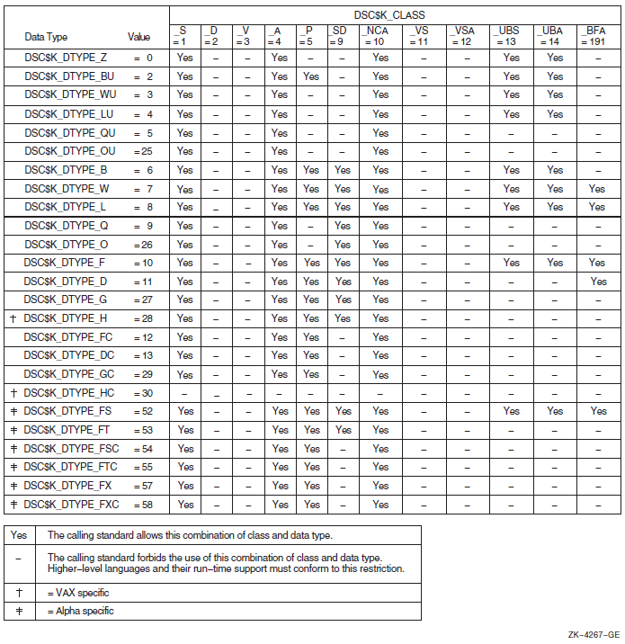
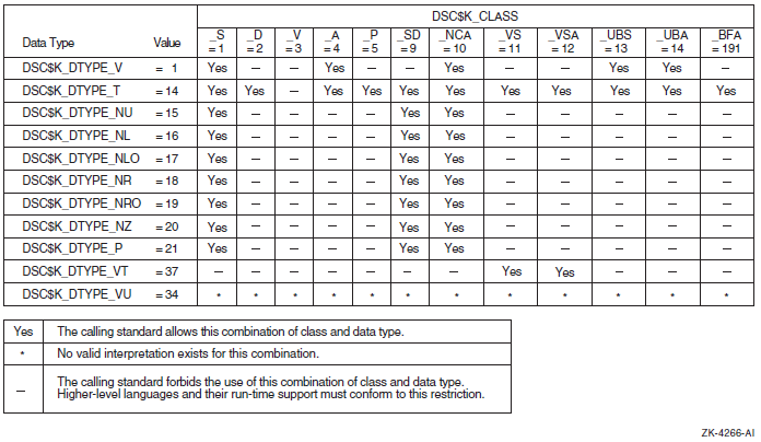
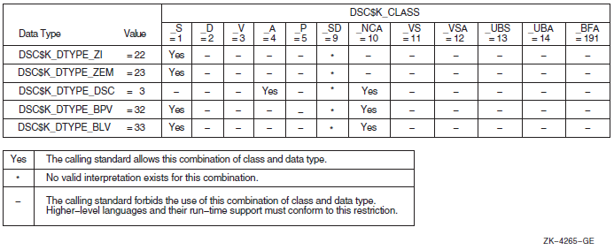
2.7. Function Value Return
A function is a routine that returns a single value to the calling routine. The function value represents the value of the expression in the return statement. As specified by the calling standard, a function value may be returned as an actual value in R0.
2.7.1. Return Values on OpenVMS VAX
On OpenVMS VAX systems, if the actual function value returned is greater than 32 bits, then both R0 and R1 should be used.
2.7.2. Return Values on OpenVMS Alpha
On OpenVMS Alpha systems, if the actual function returned is a floating-point value, the floating-point value is returned either in F0 or in both F0 and F1.
Immediate value
Reference
Descriptor
These mechanisms are the standard return convention because they support the language-independent data types. For information about condition values returned in R0, see Section 2.8, ''Condition Value Return''.
2.7.3. Return Values on OpenVMS IA-64
On OpenVMS IA-64 systems, values up to 128 bits are returned directly in the registers, according to the rules in Table 2.31, ''Rules for Return Values''.
Integer, enumeration, record, and set values (bit vectors) smaller than 64 bits must be zero-filled (unsigned integers, enumerations, records, sets) or sign-extended (signed integrals) to a full 64 bits. However, for unsigned 32-bit integers, bit 31 is replicated in bits 32—63.
When floating-point values are returned in floating-point registers, they are returned in the register format, rounded to the appropriate precision. When they are returned in the general registers (for example, as part of a record), they are returned in their memory format.
|
Type |
Size (Bits) |
Location of Return Value |
Alignment |
|---|---|---|---|
|
Integer/Pointer, small Record, Set |
1—64 |
R8 |
LSB |
|
IEEE single-precision floating-point (S_floating) |
32 |
F8 |
N/A |
|
IEEE double-precision floating-point (T_floating) |
64 |
F8 |
N/A |
|
IEEE single-precision complex (S_floating) |
64 |
F8, F9 |
N/A |
|
IEEE double-precision complex (T_floating) |
128 |
F8, F9 |
N/A |
|
VAX single-precision floating-point (F_floating) |
32 |
R8 |
N/A |
|
VAX double-precision floating-point (D_ and G_floating) |
64 |
R8 |
N/A |
|
VAX single-precision floating-point complex (F_floating) |
64 |
R8, R9 |
N/A |
|
VAX double-precision floating-point complex (D_ and G_floating) |
128 |
R8, R9 |
N/A |
Note
X_floating and X_floating complex are not included in this table because they are returned using he hidden parameter method.
The rules in Table 2.31, ''Rules for Return Values'' are expressed in more detail in Table 2.17, ''Unused Bits in Passed Data''. F_floating and F_floating complex values in the general registers are zero-extended (Zero64), because this most closely approximates the effect of using the Alpha register format.
Hidden Parameter
Return values other than those covered by Table 2.31, ''Rules for Return Values'' are returned in a buffer allocated by the caller. A pointer to the buffer is passed to the called procedure as a hidden first parameter, and all normal parameters are shifted one slot to make this possible. The return buffer must be aligned at a 16-byte boundary.
2.7.4. Return Values on OpenVMS x86-64
If the class is MEMORY, then the caller provides the space for the return value and passes the address of this storage in
%rdias if it were the first argument to the function. In effect, this address becomes a hidden first argument. This storage must not overlap any data visible to the callee through the other parameters in this argument list.On return
%raxwill contain the address that was passed in%rdiby the caller.If the class is INTEGER, the next available register of the sequence
%rax,%rdxis used.If the class is SSE, the next available floating-point register of the sequence
%xmm0,%xmm1is used.If the class is SSEUP, the quadword is returned in the next available 8-byte chunk of the last used floating-point register.
If the class is X87, the value is returned on the X87 stack in
%st0as an 80-bit x87 number.If the class is X87UP, the value is returned together with the previous X87 value in
%st0.If the class is COMPLEX_X87, the real part of the value is returned in
%st0and the imaginary part in%st1.
As a result scalar values and complex floating-point values are returned in
registers %rax, %rax and
%rdi, %mm0, or %mm0 and
%mm1. The exception is an IEEE complex quadruple precision
value which is returned in a caller-provided temporary location.
2.8. Condition Value Return
An OpenVMS system routine can indicate success or failure to the calling program by returning a condition value. In addition, an error condition to the calling program can return as a condition value in R0 (R8, R9 for I64) or by error signaling.
A condition value in R0 (R8, R9 for I64), also called a return status or completion code, is either a success (bit 0 = 1) value or an error condition (bit 0 = 0) value. In an error condition value, the low-order 3 bits specify the severity of the error (see Figure 2.19, ''Format of a Condition Value''). Bits <27:16> contain the facility number, and bits <15:3> indicate the particular condition. Bits <31:28> are the control field. When the called procedure returns a condition value, the calling program can test R0 and choose a recovery path. A general guideline to follow when testing for success or failure is that all success codes have odd values and all error codes have even values.
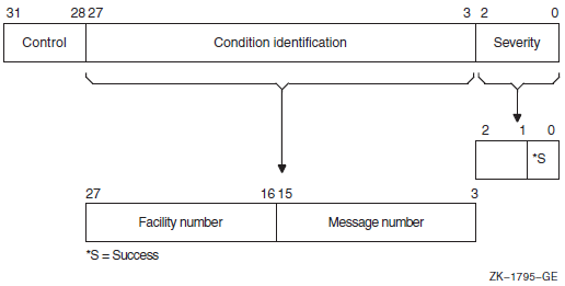
When the completion code is signaled, the calling program must establish a handler to get control and take appropriate action. (See VSI OpenVMS Programming Concepts Manual, Volume I or the VSI OpenVMS Calling Standard for a description of signaling and condition handling and for more information about the condition value).
2.9. MACRO Compiler Register Mapping
2.9.1. MACRO Register Usage and Mapping for I64
Because the I64 calling standard diverges from the Alpha and VAX calling standards regarding the use of registers and register mapping, and because MACRO-32 assumes that registers are preserved across calls, the MACRO compiler maps registers to allow existing code to compile unmodified.
If you use OpenVMS high-level languages, the register and register mapping differences in the calling standards are handled by the compilers and are not exposed to your code. However, if your code uses MACRO-32, C #pragmalinkages, or BLISS linkages, your code might have to take into account the differences in register mapping.
This section describes I64 register usage and mapping.
2.9.1.1. I64 Register Usage Compared with Alpha and VAX
OpenVMS IA-64 systems employ 32 integer registers, R0 through R31, with R0 being a read-only register that contains 0. This is different from OpenVMS Alpha, where R31 is a read-write register that contains 0.
In addition, the I64 calling standard has been written to be highly compatible with the Intel calling standard, and is quite different from the OpenVMS Alpha calling standard. For example, the standard return registers on IA-64 are R8/R9, not R0/R1 as on Alpha. The I64 calling standard reserves R1 as the GP (global pointer), does not include a standardized FP (frame pointer), and only has R4 through R7 as preserved across calls, not R2 through R15 as on Alpha.
Registers 2 through 11 are preserved on OpenVMS VAX
Registers 2 through 15 are preserved on OpenVMS Alpha
Registers 4 through 7 are preserved on OpenVMS IA-64
I64 has more "volatile" registers
I64 returns values in R8/R9 instead of R0/R1
R0 is read only in I64
I64 reserves R1 as the GP (global pointer)
I64 does not include a standardized FP (frame pointer)
Arguments are also passed in stacked registers in I64. R32—R39 are used as incoming argument registers.
2.9.1.1.1. I64 Register Mapping in MACRO Compiler
The OpenVMS MACRO compiler compiles MACRO-32 source code written for OpenVMS VAX systems (the VAX MACRO assembler) into machine code that runs on OpenVMS Alpha and OpenVMS IA-64 systems. Because MACRO-32 source code is written with the VAX and Alpha calling standards in mind, the compiler performs several transformations to allow existing code to compile unmodified with the I64 compiler.
|
OpenVMS VAX/OpenVMS Alpha Register in Source Code |
OpenVMS IA-64 Register Used in Generated Code |
|---|---|
|
R0 |
R8 |
|
R1 |
R9 |
|
R2 |
R28 |
|
R3 |
R3 |
|
R4 |
R4 |
|
R5 |
R5 |
|
R6 |
R6 |
|
R7 |
R7 |
|
R8 |
R26 |
|
R9 |
R27 |
|
R10 |
R10 |
|
R11 |
R11 |
|
R12 |
R30 |
|
R13 |
R31 |
|
R14 |
R20 |
|
R15 |
R21 |
|
R16 |
R14 |
|
R17 |
R15 |
|
R18 |
R16 |
|
R19 |
R17 |
|
R20 |
R18 |
|
R21 |
R19 |
|
R22 |
R22 |
|
R23 |
R23 |
|
R24 |
R24 |
|
R25 |
R25 |
|
R26 |
Itanium stacked register |
|
R27 |
Itanium stacked register |
|
R28 |
Itanium stacked register |
|
R29 |
R29 |
|
R30 |
R12 |
|
R31 |
R0 |
The register mapping was carefully chosen based on which registers were preserved across calls, which registers may be modified across calls, and which registers are volatile and do not even survive into or out of a call.
As on Alpha, MACRO-32 references to AP are mapped by the compiler to the appropriate location depending on whether the arguments have been saved to the stack. To support references to FP, the compiler creates an FP value where needed. The compiler supports references to 0 (FP) to establish condition handlers just like on VAX and Alpha.
The compiler does not provide any syntax for accessing I64 registers directly without going through the mapping table.
The automatic register mapping done by the compiler allows many MACRO-32 programs (including those that access Alpha registers R16—R31) to compile without modifications.
Note, however, that use of registers R16—R21 as routine parameters on Alpha is not portable to I64. Use PUSHL to pass parameters to a CALL, and use 4(AP), 8(AP), and so forth in the called routine to refer to them. The compiler will generate the correct register references instead of the stack references implied by the VAX operands.
on IA-64 systems, the compiler continues to recognize many of the EVAX_* built-ins that provide direct access to Alpha instructions on Alpha systems. These built-ins will generate one or more I64 instructions to perform the same logical operation. See the VSI OpenVMS MACRO Compiler Porting and User's Guide for a complete list of which EVAX_* built-ins are also supported on IA-64.
2.9.1.1.2. Use of MACRO Linkage Directives to Preserve Registers
For IA-64 systems, add linkage directives (.CALL_LINKAGE,.DEFINE_LINKAGE, or .USE_LINKAGE) to mark VAX CALLS or CALLG instructions that call routines that return values in registers other than R0 or R1, or to JSB to routines written in a language other than MACRO-32. These directives look similar to the .CALL_ENTRY directive and specify input, output, preserved, and scratch masks. In addition, they also have a language keyword to provide an alternative quick specification.
The .CALL_LINKAGE directive associates a named or anonymous linkage with a routine name. When the compiler sees a CALLS, CALLG, JSB, BSBB, or BSBW instruction with the routine name as the target, it will use the associated linkage to decide which registers need to be saved and restored around the call.
The .USE_LINKAGE directive establishes a temporary named or anonymous linkage that will be used by the compiler for the next CALLS, CALLG, JSB, BSBB, or BSBW instruction processed in lexical order. This directive is used when the target of the next CALLS, CALLG, JSB, BSBB, or BSBW instruction is not a name, but a run-time value (for example, CALLS #0, (R6)). When the compiler sees the next CALLS, CALLG, JSB, BSBB, or BSBW instruction, it will use the associated linkage to decide which registers need to be saved and restored around the call. After the instruction is processed, the temporary linkage is reset to null.
The .DEFINE_LINKAGE directive defines a named linkage that can be used with subsequent .CALL_LINKAGE or .USE_LINKAGE directives.
If your MACRO-32 code uses a CALLS or CALLG instruction to access routines that return values in registers other than R0 or R1, the contents of the saved and restored registers may not be what you expect. Existing MACRO-32 code traditionally assumes that registers R2—R11 and R15 are preserved and returned across calls. For CALLS and CALLG instructions, the MACRO compiler automatically saves and restores registers R2—R3 and R8—R15 in case the target of the call is not MACRO-32. However, this means that changes made to these registers by the routine call are undone. This can cause problems if the routine return values were in registers other than R0—R1.
M1.mar
   calls #3,g^body_scan

M2.mar
   Body_scan:
   .call_entry preserve=<r6,r7,r8>, output=<r2,r3,r4,r5,r9>
.call_linkage rtn_name=body_scan preserve=<r6,r7,r8> -
                                 output=<r2,r3,r4,r5,r9>
For JSB instructions, the MACRO compiler assumes that the target is also MACRO-32 and does not save and restore anything. The compiler assumes that all registers flow in and out of the target routine. Alpha high-level language compilers would have preserved registers R2—R15. However, I64 high-level language compilers preserve only registers R4—R7.
.call_linkage rtn_name=body_scan preserve=<r6,r7,r8> -
output=<r2,r3,r4,r5,r9>M1.mar jsb search_path M2.bli linkage l = jsb(register=0) : global(wrk=10,prc=11) global routine search_path : l = begin . . . End;
  .call_linkage rtn_name=search_path language=other -
output=<r10,r11>.use_linkage language=other jsb (r5)
See the VSI OpenVMS MACRO Compiler Porting and User's Guide for additional information.
2.9.2. MACRO Register Usage and Mapping for x86-64
2.9.3. High-Level Language Compiler Register Mapping
If you use OpenVMS high-level languages, the register and register mapping differences in the calling standards are handled by the compilers and are not exposed to your code. However, if your code uses C #pragma linkages or BLISS linkages to interface with MACRO-32 source code, your code might have to take into account the differences in register mapping.
BLISS added a new qualifier and source level switch to enable register mapping for
register numbers in linkage and register declarations. It is off by default. BLISS
also has additional support for linkages that reference arguments. The C compiler
changed the #pragma linkage to map the registers by default,
along with additional support for linkages that reference arguments or floating
registers. There are new pragmas to get unmapped linkages.
See your compiler documentation for additional information.
Chapter 3. Calling Run-Time Library Routines
The OpenVMS Run-Time Library is a set of language-independent routines that establish a common run-time environment for user programs. The procedures ensure correct operation of complex language features and help enforce consistent operations on data across languages.
The VSI OpenVMS Calling Standard describes the mechanisms used by OpenVMS languages for invoking routines and passing data between them. In effect, this standard describes the interface between your program and the run-time library routines that your program calls. This chapter describes the basic methods for coding calls to run-time library routines from an OpenVMS common language.
3.1. Overview
When you call a run-time library routine from your program, you must furnish whatever arguments the routine requires. When the routine completes execution, in most cases it returns control to your program. If the routine returns a status code, your program should check the value of the code to determine whether or not the routine completed successfully. If the return status indicates an error, you may want to change the flow of execution of your program to handle the error before returning control to your program.
When you log in, the operating system creates a process that exists until you log out. When you run a program, the system activates an executable image in your process. This image consists of a set of user procedures.
From the run-time library's point of view, user procedures are procedures that exist outside the run-time library and that can call run-time library routines. When you write a program that calls a run-time library routine, the run-time library views your program as a user procedure. User procedures also can call other user procedures that are either supplied by VSI or written by you. Because an OpenVMS native-mode language compiler program exists outside the run-time library, compiler-generated programs that call any run-time library routine are also defined as a set of user procedures.
The main program, or main procedure, is the first user procedure that the system calls after calling a number of initialization procedures. A user program consists of the main program and all of the other user procedures that it calls.
Figure 3.1, ''Calling the Run-Time Library'' shows the calling relationships among a main program, other user procedures, library routines, and the operating system. In this figure, Call indicates that the calling procedures requested some information or action; Return indicates that the called procedure returned the information to the calling procedure or performed the action.
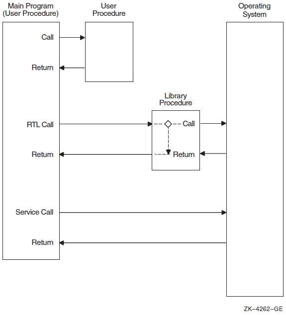
When a user procedure establishes its own condition handler. For example, LIB$SIGNAL operates by searching for and calling user procedures that have been established as condition handlers (see the VSI OpenVMS RTL Library (LIB$) Manual for more information).
When a user procedure passes to a routine the address of another procedure that the library will call later. For example, when your program calls LIB$SHOW_TIMER, you can pass the address of an action routine that LIB$SHOW_TIMER will call to process timing statistics.
3.2. Call Instructions
CALL — Call procedure from a high-level language
CALLS — Call procedure with stack argument list instruction (VAX MACRO)
CALLG — Call procedure with general argument list instruction (VAX MACRO)
JSB — Jump to subroutine instruction (for VAX systems only)
JSR — Jump to subroutine instruction (MACRO-64)
High-level languages do not differentiate between CALLS and CALLG. They use a CALL statement or a function reference to invoke a run-time library routine.
VAX MACRO does not differentiate between functions and subroutines in its CALLS and CALLG instructions.
Only VAX MACRO and BLISS programs on VAX systems can explicitly access the JSB entry points that are provided for some routines in the run-time library. You cannot write a program to access the JSB entry points directly from a high-level language.
3.2.1. Facility Prefix and Routine Name
fac$symbol|
|
A 2- or 3-character facility name |
|
|
A 1- to 27-character symbol |
The facility names are maintained in a systemwide registry. A unique, 12-bit facility number is assigned to each facility name for use in (1) condition value symbols, and (2) condition values in procedure return status codes, signaled conditions, and messages. The high-order bit of this number is 0 for facilities assigned by VSI and 1 for those assigned by Application Project Services (APS) and customers. For further information, refer to the VSI OpenVMS Calling Standard.
|
CVT$ |
Convert routines |
|
DTK$ |
DECtalk routines |
|
LIB$ |
Library routines |
|
MTH$ |
Mathematics routines |
|
OTS$ |
General-purpose routines |
|
PPL$ |
Parallel processing routines |
|
SMG$ |
Screen management routines |
|
STR$ |
String-handling routines |
3.2.2. The RTL Call Entry
Arguments passed to a routine must be listed in your call entry in the order shown in the format section of the routine description. Each argument has four characteristics: OpenVMS usage, data type, access type, and passing mechanism. These characteristics are described in Chapter 1, "Call Format to OpenVMS Routines".
Some arguments are optional. Optional arguments are indicated by brackets in the routine descriptions. When your program invokes a run-time library routine using a CALL entry point, you can omit optional arguments at the end of the argument list. If the optional argument is not the last argument in the list, you must either pass a zero by value or use a comma to indicate the place of the omitted argument. Some languages, such as C, require that you pass zero by value for trailing optional arguments. See your language processor documentation for further information.
On VAX systems, the calling program passes an argument list of longwords to a called routine; each longword in the argument list specifies a single argument. Note that a 64-bit floating-point argument would count as 2 longword arguments in the list.
On Alpha systems, the calling program passes arguments in an argument item sequence; each quadword in the sequence specifies a single argument item. Note that the argument item sequence is formed using R16–21 or F16–21 (a register for each argument). The argument item sequence can have a mix of integer and floating-point items that use both register types but must not repeat the same number.
For I64, parameters are passed in a combination of general registers, floating-point registers, and memory, as illustrated in Figure 2.12, ''Parameter Passing in Registers and Memory''.The first eight parameters are passed in R32 through R39, with the parameter count in R25 and subsequent parameters in quadwords on the stack.
In the Alpha, VAX, and I64 environments, the called routine interprets each argument using one of three standard passing mechanisms: by value, by reference, or by descriptor. For more information on arguments, see Section 2.4, ''Argument List'' and Section 2.5, ''Argument Passing Mechanisms''.
LIB$GET_INPUT get-str [,prompt-str] [,out-len] INTEGER*4 STAT
.
.
.
STAT = LIB$GET_INPUT (GET_STR,PROMPT,LENGTH)
STAT = LIB$GET_INPUT (GET_STR,PROMPT)
STAT = LIB$GET_INPUT (GET_STR,PROMPT,)
STAT = LIB$GET_INPUT (GET_STR,,LENGTH)
STAT = LIB$GET_INPUT (GET_STR)
STAT = LIB$GET_INPUT (GET_STR,)
STAT = LIB$GET_INPUT (GET_STR,%VAL(0))The following examples illustrate the standard mechanism for calling an external procedure, subroutine, or function in most high-level languages.
BASIC
    CALL LIB$MOVTC(SRC, FILL, TABLE, DEST)

    STATUS = LIB$GET_INPUT(STRING, 'NAME:')
BLISS
    LOCAL
        MSG_DESC : BLOCK [8,BYTE];

    MSG_DESC [DSC$B_CLASS] = DSC$K_CLASS_S;
    MSG_DESC [DSC$B_DTYPE] = DSC$K_DTYPE_T;
    MSG_DESC [DSC$W_LENGTH] = 5;
    MSG_DESC [DSC$A_POINTER] = MSG;

    STATUS = LIB$PUT_OUTPUT(MSG_DESC);
C
 #include <lib$routines.h>
 #include <descrip.h>

     $DESCRIPTOR(name, "Name:");
     struct dsc$descriptor_s string:
        .
        .
        .
      status = lib$get_input(&string, &name);
COBOL
    CALL LIB$MOVTC USING BY DESCRIPTOR
        SRC,
        FILL,
        TABLE,
        DEST,
        GIVING RET-STATUS.
FORTRAN
    CALL LIB$MOVTC(SRC, FILL, TABLE, DEST)

    STATUS = LIB$GET_INPUT(STRING, 'NAME:')
Pascal
RET_STATUS := LIB$MOVTC (SRC, FILL, TABLE, DEST);PL/I
    CALL LIB$MOVTC(SRC, FILL, TABLE, DEST);

    STATUS = LIB$GET_INPUT(STRING, 'NAME:');
VAX MACRO
    CALLS     #2,G^LIB$GET_INPUT

    CALLG     ARGLIST, G^LIB$GET_VM

    JSB       G^MTH$SIN_R4
As these examples show, high-level languages use different forms of the call statement. Each language's user guide gives specific information about calling the run-time library from that language.
3.2.2.1. JSB Call Entries (VAX Only)
On VAX systems, JSB entry point names follow the naming conventions explained in Section 3.2.1, ''Facility Prefix and Routine Name'', except that they include a suffix indicating the number of the highest register accessed or modified. This suffix helps ensure that the calling program and the called routine agree on the number of registers that the called routine is going to change.
JSB G^MTH$SIN_R4 ;F_floating sine uses R0 through R4JSB entry points are available only to VAX MACRO and VAX BLISS programs. No VAX high-level language provides a mechanism for accessing JSB entry points.
3.2.3. Returns from an RTL Routine
On VAX systems, some run-time library routines return a function value. Typically on a VAX system, the return is in the form of a 32-bit value in register R0 or a 64-bit value in registers R0 and R1. In high-level languages, statuses or function return values in R0 appear as the function result. When a routine returns a function value in R0, it cannot also use R1 to return a status code. Therefore, such a procedure signals errors rather than returning a status. For more information, refer to the VSI OpenVMS Calling Standard or the description of LIB$SIGNAL in the VSI OpenVMS RTL Library (LIB$) Manual.
On Alpha systems, a standard function returns its function value in R0, F0, or F0 and F1. A function value of less than 64 bits returned by immediate value in R0 is zero-extended or sign-extended to a full quadword as required by the data type. Note that a floating function value is returned by immediate value in F0 or in F0 and F1.
For I64, values up to 128 bits are returned directly in the registers (R8, R9 or F8, F9), according to the rules in Table 2.31, ''Rules for Return Values''. Integer, enumeration, record, and set values (bit vectors) smaller than 64 bits must be zero-filled (unsigned integers, enumerations, records, sets) or sign-extended (signed integrals) to a full 64 bits. However, for unsigned 32-bit integers, bit 31 is replicated in bits 32-63.
When floating-point values are returned in floating-point registers, they are returned in the register format, rounded to the appropriate precision. When they are returned in the general registers (for example, as part of a record), they are returned in their memory format.
3.2.3.1. Facility Return Status and Condition Value Symbols
fac$_abcmnoxyz|
|
The 2- or 3-letter facility symbol |
|
|
The first 3 letters of the first word of the associated message |
|
|
The first 3 letters of the next word |
|
|
The first 3 letters of the third word, if any |
|
SS$_NORMAL |
Routine successfully completed |
|
LIB$_INSVIRMEM |
Insufficient virtual memory |
|
MTH$_FLOOVEMAT |
Floating overflow in mathematics library procedure |
|
OTS$_FATINTERR |
Fatal internal error in a language-independent support procedure |
|
LIB$_SCRBUFOVF |
Screen buffer overflow |
3.3. Calling a Library Procedure in VAX MACRO (VAX Only)
This section describes how to code MACRO calls to library routines using a CALLS, CALLG, or JSB instruction for VAX systems. The routine descriptions that appear later in this manual describe the entry points for each routine. You can use either a CALLS or a CALLG instruction to invoke a procedure with a CALL entry point. You must use a JSB instruction to invoke a procedure with a JSB entry point. All MACRO calls are explicitly defined.
3.3.1. VAX MACRO Calling Sequence
All run-time library routines have a CALL entry point. Some routines also have a JSB entry point. In MACRO, you invoke a CALL entry point with a CALLS or CALLG instruction. To access a JSB entry point, use a JSB instruction.
For CALLS, the calling procedure pushes the argument list onto the stack (in reverse order) before performing the call. The list is automatically removed from the stack upon return.
For CALLG, the calling program specifies the address of the argument list, which can be anywhere in memory. This list remains in memory upon return.
Both of these instructions have the same effect on the called procedure.
JSB instructions execute faster than CALL instructions. They do not set up a new stack frame, do not change the enabling of hardware traps or faults, and do not preserve the contents of any registers before modifying them. For these reasons, you must be careful when invoking a JSB entry point in order to prevent the loss of information stored by the calling program.
Whichever type of call you use, the actual reference to the procedure entry point should use general-mode addressing (G^). This ensures that the linker and the image activator are able to locate the module within the shareable image.
In most cases, you have to tell a library routine where to find input values and store output values. You must select a data type for each argument when you code your program. Most routines accept and return 32-bit arguments.
For input arguments of byte, word, or longword values, you can supply a constant value, a variable name, or an expression in the run-time library routine call. If you supply a variable name for the argument, the data type of the variable must be as large as or larger than the data types that the called procedure requires. For example, if the called procedure expects a byte in the range 0 to 100, you can use a variable data type of a byte, word, or longword with a value between 0 and 100.
For each output argument, you must declare a variable of exactly the length required to avoid extraneous data. For example, if the called procedure returns a byte value to a word-length variable, the leftmost 8 bits of the variable <15:8> are not overwritten on output. Conversely, if a procedure returns a longword value to a word-length variable, it modifies variables in the next higher word.
3.3.2. VAX MACRO CALLS Instruction Example
        .PSECT DATA     PIC,USR,CON,REL,GBL,NOSHR,NOEXE,RD,WRT,NOVEC

MEM:    .LONG   0                       ; Longword to hold address of
                                        ; allocated memory
LEN:    .LONG   700                     ; Number of bytes to allocate

        .PSECT  CODE    PIC,USR,CON,REL,GBL,SHR,EXE,RD,NOWRT,NOVEC

        .ENTRY   PROG, ^M<>

        PUSHAL   MEM                    ; Push address of longword
                                        ; to receive address of block
        PUSHAL   LEN                    ; Push address of longword
                                        ; containing number of bytes
                                        ; desired
        CALLS    #2, G^LIB$GET_VM       ; Allocate memory
        BLBC     R0, 1$                 ; Branch if memory not available
        RET
1$:     PUSHL    R0                     ; Signal the error
        CALLS    #1, G^LIB$SIGNAL
        RET

        .END     PROG
Because the stack grows toward location 0, arguments are pushed onto
the stack in reverse order from the order shown in the general
format for the routine. Thus, the
base-address argument, here called
START, is pushed first, and then the
number-bytes argument, called LEN.
Upon return from LIB$GET_VM, the calling
program tests the return status (ret-status),
which is returned in R0 and branches to an appropriate error routine
if an error occurred.
3.3.3. VAX MACRO CALLG Instruction Example
ARGLST:
        .LONG         2               ; Argument list count
        .ADDRESS      LEN             ; Address of longword containing
                                      ; the number of bytes to allocate.
        .ADDRESS      START           ; Address of longword to receive
                                      ; the starting address of the
                                      ; virtual memory allocated.

LEN:    .LONG         20              ; Number of bytes to allocate
START:  .BLKL         1               ; Starting address of the virtual
                                      ; memory.


        CALLG  ARGLIST, G^LIB$GET_VM  ; Get virtual memory
        BLBC   R0, ERROR              ; Check for error
        BRB    10$
3.3.4. VAX MACRO JSB Entry Points
A procedure's JSB entry point name indicates the highest numbered register that the procedure modifies. Thus, a procedure with a suffix Rn modifies registers R0 through Rn. (You should always assume that R0 and R1 are modified). The calling program loads the arguments in the registers before the JSB instruction is executed.
NUM:    .FLOAT      0.7853981           ; Constant P1/4
        MOVF        NUM, R0             ; Set up input argument
        JSB         G^MTH$SIN_R4        ; Call F_floating sine procedure
                                        ; Return with value in R0
In this example, R4 in the entry point name indicates that MTH$SIN_R4 changes the contents of registers R0 through R4. The routine does not reference or change the contents of registers R5 through R11.
The entry mask of a calling procedure should specify all the registers to be saved if the procedure invokes a JSB routine. This step is necessary because a JSB procedure does not have an entry mask and thus has no way to specify registers to be saved or restored.
Procedure B modifies the contents of R2 through R6, so the contents of these registers are preserved at the time of the call.
Procedure B then invokes procedure C by means of a JSB entry point.
Procedure C modifies registers R0 through R7.
When control returns to procedure B, R7 has been modified, but when procedure B passes control back to procedure A, it restores only R2 through R6. Thus, the contents of R7 are unpredictable, and program A does not execute as expected. Procedure B should be rewritten so that R2 through R7 are saved in procedure B's entry mask.
     .ENTRY  PROC, ^M <R2, R3, R4, R5>    ; Save R2:R5
     MOVF    @4(AP), R0                   ; R0 = A
     JSB     G^MTH$SIN_R4                 ; R0 = SIN(A)
     MOVF    R0 , R5                      ; Copy result to register
                                          ; not modified by MTH$SIN
     MOVF    @8(AP) , R0                  ; R0 = B
     JSB     G^MTH$SIN_R4                 ; R0 = SIN(B)
     MULF    R5 , R0                      ; R0 = SIN(A)SIN(B)
     RET                                  ; Return
3.3.5. Return Status
Your VAX MACRO program can test for errors by examining segments of the 32-bit status code returned by a run-time library routine.
To test for errors, check for a zero in bit 0 using a Branch on Low Bit Set (BLBS) or Branch on Low Bit Clear (BLBC) instruction.
To test for a particular condition value, compare the 32 bits of the return status with the appropriate return status symbol using a Compare Long (CMPL) instruction or the run-time library routine LIB$MATCH_COND.
Using the .EXTRN symbol directive. This causes the assembler to generate an external symbol declaration.
Using the $
facDEF macro call. Calling the $LIBDEF macro, for example, causes the assembler to define all LIB$ condition values.By default. The assembler automatically declares the condition value as an external symbol that is defined as a global symbol in the run-time library.
        $SSDEF                                  ; Define SS$ symbols
        $DSCDEF                                 ; Define DSC$ symbols
        .PSECT   $DATA
PROMPT_D:                                       ; Descriptor for prompt
        .WORD    PROMPT_LEN                     ; Length field
        .BYTE    DSC$K_DTYPE_T                  ; Type field is text
        .BYTE    DSC$K_CLASS_S                  ; Class field is string
        .ADDRESS PROMPT                         ; Address

PROMPT: .ASCII   /NAME: /                       ; String descriptor
PROMPT_LEN = . - PROMPT                         ; Calculate length of
                                                ; string

STR_LEN = 30                                    ; Use 30-byte string
STRING_D:                                       ; Input string descriptor
        .WORD    STR_LEN                        ; Length field
        .BYTE    DSC$K_DTYPE_T                  ; Type field in text
        .BYTE    DSC$K_CLASS_S                  ; Class field is string
        .ADDRESS STR_AREA                       ; Address
STR_AREA: .BLKB   STR_LEN                       ; Area to receive string

                 .PSECT $CODE
                 .ENTRY START , ^M<>
                 PUSHAQ PROMPT_D                ; Push address of prompt
                                                ; descriptor
                 PUSHAQ STRING_D                ; Push address of string
                                                ; descriptor

                 CALLS  #2 , G^LIB$GET_INPUT    ; Get input string
                 BLBS   R0 , 10$                ; Check for success
                 CMPL   R0 , #LIB$_INPSTRTRU    ; Error: Was it
                                                ; truncated string?
                 BEQL   10$                     ; No, more serious error
                 PUSHL  R0
                 CALLS  #1 , G^LIB$SIGNAL

10$:             MOVL   #SS$_NORMAL , R0        ; Success, or name too
                                                ; long
                 RET
                .END    START
3.3.6. Function Return Values in VAX MACRO (VAX and Alpha)
Function values are generally returned in R0 (32-bit values) or R0 and R1 (64-bit values). A MACRO program can access a function value by referencing R0 or R0 and R1 directly. For functions that return a string, the address of the string or the address of its descriptor is returned in R0. If a function needs to return a value larger than 64 bits, it must return the value by using an output argument.
JSB entry points in the MTH$ facility return H_floating values in R0 through R3.
- One routine, MTH$SINCOS, returns two function values: the sine and the cosine of an angle. Depending on the data type of the function values, the function values are returned in the following registers:
F_floating
R0 and R1
D_floating
R0 through R3
G_floating
R0 through R3
H_floating
R0 through R7
As in the case of output arguments, a variable declared to receive the function values must be the same length as the value.
3.4. Calling a Library Routine in BLISS
No value.
A function value (typically, an integer or floating point number). For example, MTH$SIN returns its result as an F_floating value in R0 on VAX systems, in F0 on Alpha systems, or in R8 on IA-64 systems.
On Alpha processors, BLISS cannot access floating point registers. Direct use of the I64 floating-point registers is not supported.
A return status (typically, a 32-bit condition value) indicating that the routine has either executed successfully or failed. For example, LIB$GET_INPUT returns a return status in R0 (R8, R9 for I64). If the routine executes successfully, it returns SS$_NORMAL; if not, it returns one of several possible error condition values. BLISS treats the return status like any other value.
3.4.1. BLISS Calling Sequence
Scalar arguments are usually passed to run-time library routines by reference. Thus, when a BLISS program passes a variable, the variable appears with no preceding period in the procedure-call actual argument list. A constant value can be easily passed by using the %REF built-in function.
MODULE SHOWTIME(IDENT='1-1' %TITLE'Print time', MAIN=TIMEOUT)=
BEGIN
LIBRARY 'SYS$LIBRARY:STARLET';  ! Defines system services, etc.

MACRO
    DESC[]=%CHARCOUNT(%REMAINING),  ! VAX string descriptor
        UPLIT BYTE(%REMAINING) %;   !   definition
BIND
        FMTDESC=UPLIT( DESC('At the tone, the time will be ',
                %CHAR(7), '!%T' ));
EXTERNAL ROUTINE
        LIB$PUT_OUTPUT: ADDRESSING_MODE(GENERAL);

ROUTINE TIMEOUT
        =
        BEGIN
        LOCAL
            TIMEBUF: VECTOR[2],        ! 64-bit system time
            MSGBUF: VECTOR[80,BYTE],   ! Output message buffer
            MSGDESC: BLOCK[8,BYTE],    ! Descriptor for message buffer
            RSLT: WORD;                ! Length of result string


!+
! Initialize the fields of the string descriptor.
!-
        MSGDESC[DSC$B_CLASS]=DSC$K_CLASS_S;
        MSGDESC[DSC$B_DTYPE]=DSC$K_DTYPE_T;
        MSGDESC[DSC$W_LENGTH]=80;
        MSGDESC[DSC$A_POINTER]=MSGBUF[0]

        $GETTIM(TIMADR=TIMEBUF);       ! Get time as 64-bit integer

        $FAOL(CTRSTR=FMTDESC,          ! Format descriptor
            OUTLEN=RSLT,               ! Output length (only a word!)
            OUTBUF=MSGDESC,                     ! Output buffer desc.
            PRMLST= %REF(TIMEBUF));             ! Address of 64-bit
                                                !  time block
        MSGDESC [DSC$W_LENGTH] = .RSLT;         ! Modify output desc.
        RETURN (LIB$PUT_OUTPUT(MSGDESC);        ! Return status
        END;
END
ELUDOM
3.4.2. Accessing a Return Status in BLISS
STATUS = LIB$PUT_OUTPUT(MSG_DESC);
IF NOT .STATUS THEN LIB$STOP(.STATUS);
3.4.3. Calling JSB Entry Points from BLISS
Note
I64 register usage differs from that of Alpha and VAX. If you use OpenVMS high-level languages, the register and register mapping differences in the calling standards are handled by the compilers and are not exposed to your code. However, if your code uses BLISS linkages to interface with MACRO-32 source code, your code might have to take into account the differences in register mapping.
BLISS added a new qualifier and source level switch to enable register mapping for register numbers in linkage and register declarations. It is off by default. BLISS also has additional support for linkages that reference arguments.
See your compiler documentation for additional information.
MODULE JSB_LINK (MAIN = MATH_JSB,     ! Example of using JSB linkage
        IDENT = '1-001',
        ADDRESSING_MODE(EXTERNAL = GENERAL)) =
BEGIN
LINKAGE
        LINK_MATH_R4 = JSB (REGISTER = 0;  ! input reg
                            REGISTER = 0): ! output reg
                       NOPRESERVE (0,1,2,3,4)
                       NOTUSED (5,6,7,8,9,10,11);
EXTERNAL ROUTINE
        MTH$SIND_R4 : LINK_MATH_R4;

FORWARD ROUTINE
        MATH_JSB;
LIBRARY 'SYS$LIBRARY:STARLET.L32';

ROUTINE MATH_JSB =                  ! Routine

    BEGIN
    LOCAL
        INPUT_VALUE : INITIAL (%E'30.0'),
        SIN_VALUE;

!+
! Get the sine of single floating 30 degrees.  The input, 30 degrees,
! is passed in R0, and the answer, is returned in R0.  Registers
! 0 to 4 are modified by MTH$SIND_R4.
!-

    MTH$SIND_R4 (.INPUT_VALUE ; SIN_VALUE);

    RETURN SS$_NORMAL;
    END;                            ! End of routine

END                     ! End of module JSB_LINK
ELUDOM
Chapter 4. Calling System Services
The OpenVMS operating system kernel has many services that are made available to application and system programs for use at run time. These system services are procedures that the OpenVMS operating system uses to control resources available to processes; to provide for communication among processes; and to perform basic operating system functions, such as the coordination of input/output operations.
This chapter describes the basic methods and conventions for coding calls to system services from OpenVMS high-level languages or from an assembly language.
For more information about using the system services that support 64-bit addressing and to see example programs that demonstrate the use of these services, refer to VSI OpenVMS Programming Concepts Manual, Volume I.
4.1. Overview
System services are called by using the conventions of the VSI OpenVMS Calling Standard. The programming languages that generate VAX, Alpha, or I64 native mode instructions provide mechanisms for specifying the procedure calls.
When you call a system service from your program, you must furnish whatever arguments the routine requires. When the system service procedure completes execution, in most cases it returns control to your program. If the service returns a status code, your program should check the value of the code to determine whether or not the service completed successfully. If the return status indicates an error, you may want to change the flow of execution of your program to handle the error before returning control to your program.
When you write a program that calls a system service in the OpenVMS operating system, the operating system views your program as a user procedure. User procedures also can call other user procedures that are either supplied by VSI or written by you. Because an OpenVMS native-mode language compiler program exists outside the operating system, compiler generated programs calling any system service are also defined as a set of user procedures.
If you program in a high-level language, refer to Chapter 5, "STARLET Structures and Definitions for C Programmers" for information about the SYS$LIBRARY:SYS$LIB_C.TLB file, which is an OpenVMS Alpha and OpenVMS IA-64 library of C header files.
For VAX MACRO, system service macros generate argument lists and CALL instructions to call system services. These macros are located in the system library (see SYS$LIBRARY:STARLET.MLB). When you assemble a source program, this library is searched automatically for unresolved references. (See Appendix A, "Generic Macros for Calling System Services" for further details.) Similar macros are available for BLISS and are located in SYS$LIBRARY:STARLET.REQ.
4.2. Preserving System Integrity
As described in this document and the VSI OpenVMS System Services Reference Manual, many system services are available and suitable for application programs, but the use of some of these powerful services must be restricted to protect the performance of the system and the integrity of user processes.
For example, because the creation of permanent mailboxes uses system dynamic memory, the unrestricted use of permanent mailboxes could decrease the amount of memory available to other users. Therefore, the ability to create permanent mailboxes is controlled: a user must be specifically assigned the privilege to use the Create Mailbox (SYS$CREMBX) system service to create a permanent mailbox.
The various controls and restrictions applied to system service usage are described in this chapter. The Description section of each system service in the VSI OpenVMS System Services Reference Manual lists any privileges and quotas necessary to use the service.
4.2.1. User Privileges
The system manager, who maintains the user authorization file for the system, grants privileges for access to the protected system services. The user authorization file contains, in addition to profile information about each user, a list of specific user privileges and resource quotas.
When you log in to the system, the privileges and quotas assigned to you are associated with the process created on your behalf. These privileges and quotas are applied to every image the process executes.
When an image issues a call to a system service that is protected by privilege, the privilege list is checked. If you have the specific privilege required, the image is allowed to execute the system service; otherwise, a condition value indicating an error is returned.
For a list of privileges, see the description of the Create Process ($CREPRC) system service in the VSI OpenVMS System Services Reference Manual.
4.2.2. Resource Quotas
Many system services require certain system resources for execution. These resources include system dynamic memory and process quotas for I/O operations. When a system service that uses a resource controlled by a quota is called, the process's quota for that resource is checked. If the process has exceeded its quota, or if it has no quota allotment, an error condition value may be returned.
4.2.3. Access Modes
A process can execute at any one of four access modes: user, supervisor, executive, or kernel. The access modes determine a process's ability to access pages of virtual memory. Each page has a protection code associated with it, specifying the type of access—read, write, or no access—allowed for each mode.
For the most part, user-written programs execute in user mode; system programs executing at the user's request (system services, for example) may execute atone of the other three, more privileged access modes.
In some system service calls, the access mode of the caller is checked. For example, when a process tries to cancel timer requests, it can cancel only those requests that were issued from the same or less privileged access modes. For example, a process executing in user mode cannot cancel a timer request made from supervisor, executive, or kernel mode.
|
Access Mode |
Numeric Value |
Symbolic Name |
Privilege Rank |
|---|---|---|---|
|
Kernel |
0 |
PSL$C_KERNEL |
Highest |
|
Executive |
1 |
PSL$C_EXEC | |
|
Supervisor |
2 |
PSL$C_SUPER | |
|
User |
3 |
PSL$C_USER |
Lowest |
The symbolic names are defined by the symbolic definition macro SYS$PSLDEF.
System services that permit an access mode argument allow callers to specify only an access mode of equal or lesser privilege than the access mode from which the service was called. If the specified access mode is more privileged than the access mode from which the service was called, the less privileged access mode is always used.
To determine the mode to use, the operating system compares the specified access mode with the access mode from which the service was called. Because this operation results in an access mode with a higher numeric value (when the access mode of the caller is different from the specified access mode), the access mode is said to be maximized.
Because much of the code you write executes in user mode, you can omit the access mode argument. The argument value defaults to 0 (kernel mode), and when this value is compared with the value of the current execution mode (3, user mode), the higher value (3) is used.
4.3. System Service Call Entry
$SERVICE arga ,argb ,argc ,argdThis format indicates that the macro name of the service is
$SERVICE and that it requires four arguments, ordered as
shown and with keyword names arga, argb,
argc, and argd.
Arguments passed to a service must be listed in your call entry in the order shown in the Format section of the service description. Each argument has four characteristics: OpenVMS usage, data type, access type, and passing mechanism. These characteristics are described in Chapter 1, "Call Format to OpenVMS Routines".
The OpenVMS Alpha and OpenVMS IA-64, SYS$LIBRARY:SYS$LIB_C.TLB file contains C function prototypes for system services. These prototypes are documented in VSI OpenVMS System Services Reference Manual: A–GETUAI and VSI OpenVMS System Services Reference Manual: GETUTC–Z. For each prototype, the manuals provide the correct syntax (which shows the arguments the function accepts in the order in which it expects them), a description of each argument, and the type of data returned by the function.
Some arguments are optional. Optional arguments are indicated by brackets in the service descriptions. When your program invokes a system service by using a CALL entry point, you can omit optional arguments at the end of the argument list. If the optional argument is not the last argument in the list, you must either pass a zero by value or use a comma to indicate the place of the omitted argument. Some languages, such as C, require that you pass a zero by value for all trailing optional arguments. See your language processor documentation for further information.
return_status = sys$getdvi
                 (event_flagnum, channel, &devnam, &item_list,0,0,0);
Note that in C, you must not omit the optional trailing arguments and should pass a zero by value for these unused parameters. See your language processor documentation for further information.
The VSI OpenVMS System Services Reference Manual provides a description of each service that indicates how each argument is to be passed. Phrases such as "an address" and "address of a character string descriptor" identify reference and descriptor arguments, respectively. Terms like "Boolean value," "number," "value," or "mask" indicate an argument that is passed by value.
In the Alpha, VAX, and I64 environments, the called routine interprets each argument using one of three standard passing mechanisms: by value, by reference, or by descriptor.
On VAX systems, the calling program passes an argument list of longwords to a called service; each longword in the argument list specifies a single argument.
On Alpha systems, the calling program passes arguments in an argument item sequence; each quadword in the sequence specifies a single argument item. Note that the argument item sequence is formed using R16—R21 or F16—F21 (a register for each argument).
on IA-64 systems, the first eight parameters are passed in R32 through R39, with the parameter count in R25 and subsequent parameters in quadwords on the stack.
For more detailed information on arguments lists and passing mechanisms, see Section 2.4, ''Argument List'' and Section 2.5, ''Argument Passing Mechanisms''.
Some services also require service-specific data structures that either indicate functions to be performed or hold information to be returned. The VSI OpenVMS System Services Reference Manual includes descriptions of these service-specific data structures. You can use this information and information from your programming language manuals to define such service-specific item lists.
4.4. System Service Completion
When a system service completes, control is returned to your program. You can specify how and when control is returned to your program by choosing synchronous or asynchronous forms of system services and by enabling process execution modes.
When synchronous system services return control to your program
When asynchronous system services return control to your program
How you can synchronize the completion of asynchronous system services
How control is returned to your program when special process execution modes are enabled
4.4.1. Asynchronous and Synchronous System Services
You can execute a number of system services either asynchronously or synchronously (such as, SYS$GETJPI and SYS$GETJPIW or SYS$ENQ and SYS$ENQW). The W at the end of the system service name indicates the synchronous version of the system service.
The asynchronous version of a system service queues a request and returns control to your program. You can perform operations while the system service executes; however, you should not attempt to access information returned by the service until you check for the system service completion.
Typically, you pass to an asynchronous system service an event flag and an I/O status block or a lock status block. When the system service completes, it sets the event flag and places the final status of the request in the status block. You use the SYS$SYNCH system service to ensure that the system service has completed. You pass SYS$SYNCH the event flag and the status block that you passed to the asynchronous system service; SYS$SYNCH waits for the event flag to be set, then ensures that the system service (rather than some other program) sets the event flag by checking the status block. If the status block is still zero, SYS$SYNCH waits until the status block is filled.
The synchronous version of a system service acts exactly as if you had used the
asynchronous version followed immediately by a call to
SYS$SYNCH. If you omit the efn
argument, the service uses event flag number 0 whether you use the synchronous or
asynchronous version of a system service.
! Data structure for SYS$GETJPI
.
.
.
INTEGER*4 STATUS,
2         FLAG,
2         PID_VALUE
! I/O status block
INTEGER*2 JPISTATUS,
2         LEN
INTEGER*4 ZERO /0/
COMMON /IO_BLOCK/ JPISTATUS,
2                 LEN,
2                 ZERO
.
.
.

! Call SYS$GETJPI and wait for information
STATUS = LIB$GET_EF (FLAG)
IF (.NOT. STATUS) CALL LIB$SIGNAL (%VAL(STATUS))

STATUS = SYS$GETJPI (%VAL(FLAG),
2                    PID_VALUE,
2                    ,
2                    NAME_BUF_LEN,
2                    JPISTATUS,
2                    ,)
IF (.NOT. STATUS) CALL LIB$SIGNAL (%VAL(STATUS))
.
.
.
STATUS = SYS$SYNCH (%VAL(FLAG),
2                   JPISTATUS)
IF (.NOT. JPISTATUS) THEN
  CALL LIB$SIGNAL (%VAL(JPISTATUS))
END IF

END
4.4.2. System Service Resource Wait Mode
Normally, when a system service is called and a required resource is not available, the process is placed in a wait state until the resource becomes available. Then the service completes execution. This mode is called resource wait mode.
In a real-time environment, however, it may not be practical or desirable for a program to wait. In these cases, you can choose to disable resource wait mode so that when a required resource is unavailable, control returns immediately to the calling program with an error condition value. You can disable (and reenable) resource wait mode with the Set Resource Wait Mode (SYS$SETRWM) system service.
If resource wait mode is disabled, it remains disabled until it is explicitly reenabled or until your process is deleted. For example, if your program has disabled resource wait mode and has exited to the DCL prompt, subsequent programs or utilities invoked by this process continue to run with resource wait mode disabled and might not perform properly because they are not prepared to handle a failure to obtain a resource. In this case, you should reenable the wait mode before your program exits to the DCL prompt.
How a program responds to the unavailability of a resource depends primarily on the application and the particular service being called. In some instances, the program may be able to continue execution and retry the service call later. In other instances, it may be necessary for the program to wait for the resource and the system service to complete.
4.4.3. Condition Values Returned from System Services
When a service returns control to your program, it places a return status value in the general register R0 (R8, R9 for I64). The value in the low-order word indicates either that the service completed successfully or that some specific error prevented the service from performing some or all of its functions. After each call to a system service, you must check whether it completed successfully. You can also test for specific errors in the condition value.
The low-order bit indicates successful (1) or unsuccessful (0) completion of the service.
The low-order 3 bits, taken together, represent the severity of the error. Table 4.2, ''Severity Codes of Condition Value Returned'' lists the possible severity code values returned.
For VAX MACRO, the symbolic definition macro SYS$STSDEF defines the symbolic names. For the C programming language, the SSDEF.H file defines the symbolic names.
The remaining bits (bits 3 through 31) classify the particular return condition and the operating system component that issued the condition value. For system service return status values, the high-order word (bits 16 through 31) contains zeros.
|
Value |
Meaning |
Symbolic Name |
|---|---|---|
|
0 |
Warning |
STS$K_WARNING |
|
1 |
Success |
STS$K_SUCCESS |
|
2 |
Error |
STS$K_ERROR |
|
3 |
Informational |
STS$K_INFO |
|
4 |
Severe or fatal error |
STS$K_SEVERR |
|
5—7 |
Reserved |
SS$_codewhere code is a mnemonic describing the return condition.
SS$_NORMALSS$_ACCVIOThis condition value indicates that an access violation occurred because a service could not read an input field or write an output field.
The symbolic definitions for condition values are included in the default system library SYS$LIBRARY:STARLET.OLB. You can obtain a listing of these symbolic codes at assembly time by invoking the system macro SYS$SSDEF. To check return conditions, use the symbolic names for system condition values.
The OpenVMS operating system does not automatically handle system service failure or warning conditions; you must test for them and handle them yourself. This contrasts with the operating system's handling of exception conditions detected by the hardware or software; the system handles these exceptions by default, although you can intervene in or override the default handling by declaring a condition handler.
4.4.4. Testing the Condition Value
Each language provides some mechanism for testing the return status. Often you need only check the low-order bit, such as by a test for TRUE (success or informational return) or FALSE (error or warning return). Condition values that are returned by system services can provide information and whether the service completed successfully. The condition value that usually indicates success is SS$_NORMAL, but others are defined. For example, the condition value SS$_BUFFEROVF, which is returned when a character string returned by a service is longer than the buffer provided to receive it, is a success code. This condition value, however, gives the program additional information.
Warning returns and some error returns indicate that the service performed some, but not all, of the requested function.
The possible condition values that each service can return are described with the individual service descriptions in the VSI OpenVMS System Services Reference Manual. When you write calls to system services, read the descriptions of the return condition values to determine whether you want the program to check for particular return conditions.
To check the entire value for a specific return condition, each language provides a way for your program to determine the values associated with specific symbolically defined codes. You should always use these symbolic names when you write tests for specific conditions.
For information about how to test for these codes, see the user's guide for your programming language.
4.4.4.1. Testing the Condition Value With $VMS_STATUS_SUCCESS Macro
You can use the $VMS_STATUS_SUCCESS macro, defined in stsdef.h, to test an OpenVMS condition value. $VMS_STATUS_SUCCESS depends on the documented format of an OpenVMS condition value, and particularly on the setting of the lowest bit in a condition value. If the lowest bit is set, the condition indicates a successful status, while the bit is clear for an unsuccessful status.
$VMS_STATUS_SUCCESS is used only with condition values that follow the OpenVMS condition status value format, and not with C standard library routines and return values that follow C native status value norms. For details on the OpenVMS condition status value structure, please see VSI OpenVMS Programming Concepts Manual, Volume I. For information on the return values from the various C standard library routines, see the VSI C Run-Time Library Reference Manual for OpenVMS Systems.
RetStat = sys$dassgn( IOChan );
if (!$VMS_STATUS_SUCCESS( RetStat ))
  return RetStat;
4.4.5. Special Condition Values Using Symbolic Codes
Individual services have symbolic codes for special return conditions, argument list offsets, identifiers, and flags associated with these services. For example, the Create Process (SYS$CREPRC) system service(which is used to create a subprocess or a detached process) has symbolic codes associated with the various privileges and quotas you can grant to the created process.
The SYS$LIBRARY:SYS$LIB_C.TLB file contains the C header files for OpenVMS Alpha and OpenVMS IA-64 C data structures and definitions. For more information about SYS$LIBRARY:SYS$LIB_C.TLB, refer to Chapter 5, "STARLET Structures and Definitions for C Programmers".
The default system macro library, STARLET.MLB, contains the macro definitions for most system symbols. When you assemble a source program that calls any of these macros, the assembler automatically searches STARLET.MLB for the macro definitions. Each symbol name has a numeric value.
If your language has a method of obtaining values for these symbols, this method is explained in the user's guide.
Write a short VAX MACRO program containing the desired macros.
Assemble or compile the program and generate a listing. Using the listing, find the desired symbols and their hexadecimal values.
Define each symbol with its value within your source program.
- Create the following three-line VAX MACRO program (named JPIDEF.MAR here; you can choose any name you want):
.TITLE  JPIDEF  "Obtain values for $JPIDEF"
$JPIDEF GLOBAL          ; These MUST be UPPERCASE
.END
- On VAX, assemble and link the program to create the file JPIDEF.MAP as follows:
$ MACRO JPIDEF
$ LINK/NOEXE/MAP/FULL  JPIDEF
%LINK-W-USRTFR, image NL:[].EXE; has no user transfer address
The file JPIDEF.MAP contains the symbols defined by $JPIDEF listed both alphabetically and numerically.
On Alpha and I64, to compile the program to create the JPIDEF.MAP, enter the following:$ MACRO/MIGRATION JPIDEF $ LINK/NOEXE/MAP/FULL JPIDEF %LINK-W-USRTFR, image NL:[].EXE; has no user transfer address
Find the value of JPI$_CPUTIM and define the symbol in your program.
4.4.6. Testing the Return Condition Value for VAX MACRO
BLBC R0,errlabel ; Error if low bit clear
Programs should not test for success by comparing the return status to SS$_NORMAL. A future release of OpenVMS may add new, alternate success codes to an existing service, causing programs that test for SS$_NORMAL to fail.
CMPL #SS$_ILLEFC,R0 ; Is event flag number illegal?Note that return condition values are always longword values; however, all system services always return the same value in the high-order word of all condition values returned in R0.
4.4.7. System Messages Generated by Condition Values
When you execute a program with the DCL command RUN, the command interpreter uses the contents of R0 to issue a descriptive message if the program completes with an unsuccessful status. On IA-64, the calling standard specifies that the return status is returned in R8. As an aid to portable code, the MACRO compiler automatically maps uses of R0 to R8. See the VSI OpenVMS MACRO Compiler Porting and User's Guide for additional information.
        $READEF_S -
                EFN=#64, -
                STATE=TEST
        BSBW    ERROR
         .
         .
         .
ERROR:  BLBC    R0,10$          ; Check register 0
        RSB                     ; Success, return
10$:    RET                     ; Exit with R0 status
After a system service call, the BSBW instruction branches to the subroutine ERROR. The subroutine checks the low-order bit in register 0 and, if the bit is clear, branches to a RET instruction that causes the program to exit with the status of R0 preserved. Otherwise, the subroutine issues an RSB instruction to return to the main program.
%SYSTEM-F-UNASEFC, unassociated event flag cluster
The keyword UNASEFC in the message corresponds to the condition value SS$_UNASEFC.
|
Error |
Meaning |
|---|---|
|
SS$_ACCVIO |
The argument list cannot be read by the caller (using the
$ This meaning of SS$_ACCVIO is different from its meaning for individual services. When SS$_ACCVIO is returned from individual services, the service is called, but one or more arguments to the service cannot be read or written by the caller. |
|
SS$_INSFARG |
Not enough arguments were supplied to the service. |
|
SS$_ILLSER |
An illegal system service was called. |
4.5. Program Examples with System Service Calls
ith SYSTEM, TEXT_IO, STARLET, CONDITION_HANDLING;procedure ORION is -- Declare variables to hold equivalence name and length -- EQUIV_NAME: STRING (1..255);
pragma VOLATILE (EQUIV_NAME); NAME_LENGTH: SYSTEM.UNSIGNED_WORD; pragma VOLATILE (NAME_LENGTH); -- Declare itemlist and fill in entries. -- ITEM_LIST: STARLET.ITEM_LIST_3_TYPE (1..2) :=
(1 => (ITEM_CODE => STARLET.LNM_STRING,
BUF_LEN => EQUIV_NAME'LENGTH, BUF_ADDRESS => EQUIV_NAME'ADDRESS, RET_ADDRESS => NAME_LENGTH'ADDRESS), 2 => (ITEM_CODE => 0, BUF_LEN => 0, BUF_ADDRESS => SYSTEM.ADDRESS_ZERO, RET_ADDRESS => SYSTEM.ADDRESS_ZERO)); STATUS: CONDITION_HANDLING.COND_VALUE_TYPE;
begin -- Translate the logical name -- STARLET.TRNLNM (
STATUS => STATUS, TABNAM => "LNM$FILE_DEV", LOGNAM => "CYGNUS", ITMLST => ITEM_LIST); -- Display name if success, else signal error -- if not CONDITION_HANDLING.SUCCESS (STATUS) then
CONDITION_HANDLING.SIGNAL (STATUS); else TEXT_IO.PUT ("CYGNUS translates to """); TEXT_IO.PUT (EQUIV_NAME (1..INTEGER(NAME_LENGTH))); TEXT_IO.PUT_LINE (""""); end if; end ORION;
Ada Notes
| (The with clause names the predefined packages of declarations used in this program. SYSTEM and TEXT_IO are standard Ada packages; STARLET defines the OpenVMS system service routines, data types, and constants; and CONDITION_HANDLING defines error-handling facilities. |
| Enough space is allocated to EQUIV_NAME to hold the longest possible logical name. NAME_LENGTH will receive the actual length of the translated logical name. The VOLATILE pragma is required for variables that will be modified by means other than an assignment statement or being an output parameter to a routine call. |
| ITEM_LIST_3_TYPE is a predeclared type in package STARLET that defines the OpenVMS three-longword item list structure. |
| The dollar-sign character is not valid in Ada identifiers; package STARLET defines the
|
| COND_VALUE_TYPE is a predeclared type in package CONDITION_HANDLING that is used for return status values. |
| System services are defined in package STARLET using names that omit the prefix SYS$. The passing mechanisms are specified in the routine declaration in STARLET, so they need not be specified here. |
| In this example, any failure status from the SYS$TRNLNM service is signaled as an error. Other means of error recovery are possible; see your Ada language documentation for more details. |
10 SUB ORION
BASIC Notes
| The SUB statement defines the routine and its entry mask. |
| The DECLARE WORD NAMLEN declaration reserves a 16-bit word for the output value. |
| The COMMON (BUF) STRING NAME_STRING = 255 declaration allocates 255 bytes for the output data in a static area. The compiler builds the descriptor. |
| The SYS$ form invokes the system service as a function. Enclose the arguments in parentheses and specify them in positional order only. Specify a comma for each optional argument that you omit (including trailing arguments). |
| The input character string is specified directly in the system service call;the compiler builds the descriptor. |
| The IF statement performs a test on the low-order bit of the return status. This form is recommended for all status returns. |
MODULE ORION=

BEGIN
EXTERNAL ROUTINE
    ERROR_PROC: NOVALUE;                 ! Error processing routine

LIBRARY 'SYS$LIBRARY:STARLET.L32';       ! Library containing OpenVMS
                                         ! macros (including $TRNLNM).
                                         ! This declaration
                                         ! is required.

GLOBAL ROUTINE ORION: NOVALUE=

    BEGIN
    OWN
        NAMBUF : VECTOR[255, BYTE],       ! Output buffer
        NAMLEN : WORD,                    ! Translated string length
        ITEMS : BLOCK[16,BYTE]
                INITIAL(WORD(255,         ! Output buffer length
                        LNM$_STRING),     ! Item code
                        NAMBUF,           ! Output buffer
                        NAMLEN,           ! Address of word for
                                          ! translated
                                          ! string length
                        0);               ! List terminator

    LOCAL                                 ! Return status from
        STATUS;                           ! system service

    STATUS = $TRNLNM(TABNAM = %ASCID'LNM$FILE_DEV',
                     LOGNAME = %ASCID'CYGNUS',
                     ITMLST = ITEMS);

    IF NOT .STATUS THEN ERROR_PROC(.STATUS);

    END;
BLISS Notes
| The macro is invoked by its service name, without a suffix. Enclose the arguments in parentheses and specify them by keyword. (Keyword names correspond to the names of the arguments shown in lowercase in the system service format descriptions in the VSI OpenVMS System Services Reference Manual). |
| The return status, which is assigned to the variable STATUS, is tested for TRUE or FALSE. FALSE (low bit = 0) indicates failure or warning. |
#include <starlet.h>
C Notes
| The C language header file |
| The structure of an item list entry is defined. |
| The $DESCRIPTOR macro declares and initializes a character string
descriptor. Here, two descriptors are created for use with the
|
| The function |
| The |
| The IF statement performs a logical test following the function reference to determine whether the service completed successfully. If an error or warning occurs during the service call, the error is signaled. |
IDENTIFICATION DIVISION. PROGRAM-ID. ORION.
COBOL Notes
| The PROGRAM-ID paragraph identifies the program by specifying the program name, which is the global symbol associated with the entry point. The compiler builds the entry mask. |
| Enough bytes are allocated for the alphanumeric output data. The compiler generates a descriptor when you specify USING BY DESCRIPTOR in the CALL statement. |
| The value of the symbolic code LNM$STRING is 2. Section 4.4.5, ''Special Condition Values Using Symbolic Codes'' explains how to obtain values for symbolic codes. |
| This definition reserves a signed longword with COMP (binary) usage to receive the output value. |
| The service is called by the SYS$ form of the service name, and the name is enclosed in quotation marks. Specify arguments in positional order only, with the USING statement. You cannot omit arguments; if you are accepting the default for an argument, you must pass the default value explicitly (OMITTED in this example). You can specify explicitly how each argument is being passed: by descriptor, by reference (that is, by address), or by value. You can also implicitly specify how an argument is being passed: through the default mechanism (by reference), or through association with the last specified mechanism (thus, the last two arguments in the example are implicitly passed by value). |
| The input string is defined as alphanumeric (ASCII) data. The compiler generates a descriptor when you specify USING BY DESCRIPTOR in the CALL statement. |
| The IF statement tests RESULT for a failure status. In this case, control is passed to the routine ERROR-CHECK. |
SUBROUTINE ORION IMPLICIT NONE ! Require declaration of all symbols INCLUDE '($SYSSRVNAM)' ! Declare system service names
FORTRAN Notes
| The module $SYSSRVNAM in the FORTRAN system default library FORSYSDEF.TLB contains INTEGER and EXTERNAL declarations for each of the system services, so you need not explicitly provide these declarations in your program. Module $LNMDEF defines constants and data structures used when calling the logical name services, and module LIB$ROUTINES contains declarations for the LIB$ Run-Time Library routines. |
| The structure of an OpenVMS 3-longword item list is declared and then used to define the record variable ITEM_LIST. The second element will be used for the terminator. |
| The VOLATILE declaration is required for variables that are modified by means other than a direct assignment or as an argument in a routine call. |
| Return status variables should always be declared as longword integers. |
| The LEN intrinsic function returns the allocated length of EQUIV_NAME. The %LOC built-in function returns the address of its argument. |
| By default, FORTRAN passes arguments by reference, except for strings which are passed by CLASS_S descriptor. Arguments are omitted in FORTRAN by leaving the comma as a placeholder. All arguments must be specified or explicitly omitted. |
| A condition value can be tested for success or failure by a true/false test. For more information on testing return statuses, see the OpenVMS FORTRAN documentation. |
[INHERIT('SYS$LIBRARY:STARLET',
         'SYS$LIBRARY:PASCAL$LIB_ROUTINES')]
PROGRAM ORION (OUTPUT);

TYPE
    Item_List_Cell = RECORD CASE INTEGER OF
        1:( { Normal Cell }
            Buffer_Length : [WORD] 0..65535;
            Item_Code     : [WORD] 0..65535;
            Buffer_Addr   : UNSIGNED;
            Return_Addr   : UNSIGNED
            );
        2:( { Terminator }
            Terminator   : UNSIGNED
            );
        END;

    Item_List_Template(Count:INTEGER) = ARRAY [1..Count] OF Item_List_Cell;

VAR
    Item_List       : Item_List_Template(2);
    Translated_Name : [VOLATILE] VARYING [255] OF CHAR;
    Status          : INTEGER;

    BEGIN

    { Specify the buffer to return the translation }
    Item_List[1].Buffer_Length  := SIZE(Translated_Name.Body);
    Item_List[1].Item_Code  := LNM$_String;
    Item_List[1].Buffer_Addr  := IADDRESS(Translated_Name.Body);
    Item_List[1].Return_Addr  := IADDRESS(Translated_Name.Length);

    { Terminate the item list }
    Item_List[2].Terminator  := 0;

    { Translate the CYGNUS logical name }
    Status := $trnlnm(Tabnam := 'LNM$FILE_DEV', Lognam := 'CYGNUS',
        Itmlst := Item_List);
    IF NOT ODD(Status)
    THEN
        LIB$SIGNAL(Status)
    ELSE
        WRITELN('CYGNUS is equivalent to ',Translated_Name);

    END.
Pascal Notes
| The Pascal environment file STARLET.PEN defines OpenVMS system services, data structures and constants. PASCAL$LIB_ROUTINES declares the LIB$ Run-Time Library routines. |
| The structure of an item list entry is defined using a variant record type. |
| The VARYING OF CHAR type is a variable-length character string with two components: a word-integer length and a character string body, which in this example is 255 bytes long. The VOLATILE attribute is required for variables that are modified by means other than a direct assignment or as an argument in a routine call. |
| The functions SIZE and IADDRESS obtain the allocated size of the string body and the address of the string body and length. The returned length will be stored into the length field of the varying string Translated_Name, so that it will appear to be the correct size. |
| The definition of the SYS$TRNLNM routine in STARLET.PEN contains specifications of the passing mechanism to be used for each argument;thus, it is not necessary to specify the mechanism here. |
| The IF statement performs a logical test following the function reference to see if the service completed successfully. If an error or warning occurs during the service call, the error is signaled. |
CYGDES: .ASCID /CYGNUS/
VAX MACRO Notes
| The input character string descriptor argument is defined using the .ASCID directive. |
| The name of the table to search is defined using the .ASCID directive. |
| Enough bytes to hold the output data are allocated for an output character string argument. |
| The MACRO directive .BLKW reserves a word to hold the output length. |
| A routine name and entry mask show the beginning of executable code in a routine or subroutine. |
| A macro name that has the suffix _S or _G calls the service. You can specify arguments either by keyword (as in this example) or by positional order. (Keyword names correspond to the names of the arguments shown in lowercase in the system service format descriptions in the VSI OpenVMS System Services Reference Manual). If you omit any optional arguments (if you accept the defaults), you can omit them completely if you specify arguments by keyword. If you specify arguments by positional order, however, you must specify the comma for each missing argument. Use the number sign (#) to indicate a literal value for an argument. |
| The BLBC instruction causes a branch to a subroutine named ERROR (not shown) if the low bit of the condition value returned from the service is clear (low bit clear = failure or warning). You can use a BSBW instruction to branch unconditionally to a routine that checks the return status. |
Chapter 5. STARLET Structures and Definitions for C Programmers
This chapter describes the libraries that contain C header files for routines supplied by the OpenVMS Alpha and OpenVMS IA-64 operating systems.
5.1. SYS$STARLET_C.TLB Equivalency to STARLETSD.TLB
The SYS$STARLET_C.TLB file, which was introduced in OpenVMS Alpha Version 1.0, contains all the .H files that provide STARLET functionality equivalent to STARLETSD.TLB. The file SYS$STARLET_C.TLB, together with DECC$RTLDEF.TLB that ships with the VSI C Compiler, replaces VAXCDEF.TLB that previously shipped with the VAX C Compiler. DECC$RTLDEF.TLB contains all the .H files that support the compiler and RTL, such as STDIO.H.
RMS structures
Previously, the RMS structures FAB, NAM, RAB, XABALL, and so forth, were defined in the appropriate .H files as "struct RAB {...", for example. The .H files supplied in OpenVMS Alpha Version 1.0 define them as "struct rabdef {...". To compensate for this difference, lines of the form "#define RAB rabdef" have been added. However, there is one situation where a source change is required because of this change. If you have a private structure that contains a pointer to one of these structures and your private structure is defined (but not used) before the RMS structure has been defined, you will receive compile-time errors similar to the following:%CC-E-PASNOTMEM, In this statement, "rab$b_rac" is not a member of "rab".This error can be avoided by reordering your source file so that the RMS structure is defined before the private structure. Typically, this involves moving around "#include" statements.
LIB (privileged interface) structures
Historically, three structures from LIB (NFBDEF.H, FATDEF.H, and FCHDEF.H) have been made available as .H files. These files were shipped as .H files in OpenVMS Alpha Version 1.0 and 1.5 (not in the new SYS$STARLET_C.TLB). As of OpenVMS Alpha Version 7.0, the file SYS$LIB_C.TLB, containing all LIB structures and definitions, was added. These three .H files are now part of that .TLB and are no longer shipped separately. Source changes may be required, because no attempt has been made to preserve any existing anomalies in these files. The structures and definitions from LIB are for privileged interfaces only and are therefore subject to change.
Use of "variant_struct" and "variant_union"
In the new .H files, "variant_struct" and "variant_union" are always used; whereas previously some structures used "struct" and "union". Therefore, the intermediate structure names cannot be specified when referencing fields within data structures.
For example, the following statement:AlignFaultItem.PC[0] = DataPtr->afr$r_pc_data_overlay.afr$q_fault_pc[0];
becomes:AlignFaultItem.PC[0] = DataPtr->afr$q_fault_pc[0];Member alignment
Each of the .H files in SYS$STARLET_C.TLB saves and restores the state of "#pragma member_alignment".
Conventions The .H files in SYS$STARLET_C.TLB adhere to some conventions that were only partly followed in VAXCDEF.TLB. All constants (#defines) have uppercase names. All identifiers (routines, structure members, and so forth) have lowercase names. Where there is a difference from VAXCDEF.TLB, the old symbol name is also included for compatibility, but users are encouraged to follow the new conventions.
Use of Librarian utility to access the .H files
During installation of OpenVMS Alpha, the contents of SYS$STARLET_C.TLB are not extracted into the separate .H files. The VSI C Compiler accesses these files from within SYS$STARLET_C.TLB, regardless of the format of the #include statement. If you want to inspect an individual .H file, you can use the Librarian utility, as in the following example:$ LIBRARY /EXTRACT=AFRDEF /OUTPUT=AFRDEF.H SYS$LIBRARY:SYS$STARLET_C.TLB
Additional .H files included in SYS$STARLET_C.TLB
In addition to the .H files derived from STARLET sources, SYS$STARLET_C.TLB includes .H files that provide support for POSIX Threads Library, such as CMA.H.
5.2. NEW STARLET Definitions for C
SYS$LIBRARY:SYS$STARLET_C.TLB (or STARLET) provides C function prototypes for system services, as well as data structure definitions. The compiler searches the library file SYS$LIBRARY:SYS$STARLET_C.TLB for the STARLET header files. The definitions are consistent with the OpenVMS C language coding conventions and definitions (typedefs) used in SYS$LIBRARY:SYS$LIB_C.TLB.
To maintain source compatibility for users of STARLET.H as provided prior to OpenVMS Alpha Version 7.0, the "old style" function declarations and definitions are still provided by default. To take advantage of the new system service function prototypes and type definitions, you must explicitly enable them.
- Define the _NEW_STARLET symbol with the VSI C command line qualifier as follows:
/DEFINE=(__NEW_STARLET=1)
or
- Define the _NEW_STARLET symbol in your C source program before including the SYS$STARLET_C.TLB header files:
#define __NEW_STARLET 1

#include  <starlet.h>
#include  <vadef.h>
$ LIBRARY/OUTPUT=STARLET.H SYS$LIBRARY:SYS$STARLET_C.TLB/EXTRACT=STARLET #pragma __required_pointer_size __long
int sys$expreg_64(
struct _generic_64 *region_id_64,
unsigned __int64 length_64,
unsigned int acmode,
unsigned int flags,
void *(*(return_va_64)),
unsigned __int64 *return_length_64);
#pragma __required_pointer_size __shortFor more information about VSI C pointer size pragmas, see the VSI C User Manual.
#define __NEW_STARLET 1 /* Enable "New Starlet" features */ #include <starlet.h> /* Declare prototypes for system services */ #include <gen64def.h> /* Define GENERIC_64 type */ #include <vadef.h> /* Define VA$ constants */ #include <ints.h> /* Define 64-bit integer types */ #include <far_pointers.h> /* Define 64-bit pointer types */ { int status; /* Ubiquitous VMS status value */ GENERIC_64 region = { VA$C_P2 }; /* Expand in "default" P2 region */ VOID_PQ p2_va; /* Returned VA in P2 space */ uint64 length; /* Allocated size in bytes */ extern uint64 page_size; /* Page size in bytes */ status = sys$expreg_64( ®ion, request_size, 0, 0, &p2_va, &length ); ... }
|
Structure Used by Prototype |
Defined by Header File |
Common Prefix for Structure Member Names |
Description |
|---|---|---|---|
|
struct _acmecb |
acmedef.h |
acmedef$ |
ACM communications buffer |
|
struct _acmesb |
acmedef.h |
acmedef$ |
ACM status block |
|
struct _cluevthndl |
cluevtdef.h |
cluevthndl$ |
Cluster event handle |
|
struct _fabdef |
fabdef.h |
fab$ |
File access block |
|
struct _generic_64 |
gen64def.h |
gen64$ |
Generic quadword structure |
|
struct _ieee |
ieeedef.h |
ieee$ |
IEEE Floating point control structure |
|
struct _ile2? |
iledef.h |
ile2$ |
Item list entry 2 |
|
struct _ile3? |
iledef.h |
ile3$ |
Item list entry 3 |
|
struct _ilea_64? |
iledef.h |
ilea_64$ |
64-bit item list entry A structure |
|
struct _ileb_64? |
iledef.h |
ileb_64$ |
64-bit item list entry B structure |
|
struct _iosa |
iosadef.h |
iosa$ |
I/O status area |
|
struct _iosb |
iosbdef.h |
iosb$ |
I/O status block |
|
struct _lksb |
lksbdef.h |
lksb$ |
Lock status block |
|
struct _rabdef |
rabdef.h |
rab$ |
RMS record access block |
|
struct _secid |
seciddef.h |
secid$ |
Global section identifier |
|
struct _va_range |
va_rangedef.h |
va_range$ |
32-bit virtual address range |
Part II. I/O, System, and Programming Routines
This part of this second volume describes the I/O operations, and the system and programming routines used by run-time libraries and system services.
Chapter 6. Run-Time Library Input/Output Operations
This chapter describes the different I/O programming capabilities provided by the run-time library and illustrates these capabilities with examples of common I/O tasks.
6.1. Choosing I/O Techniques
DEC Text Processing Utility
DECforms software
Program language I/O statements
OpenVMS Record Management Services (RMS) and Run-Time Library (RTL) routines
SYS$QIO and SYS$QIOW system services
Third party-supplied device drivers to control the I/O to the device itself
High-level procedure language with several data types, relational operators, error interception, looping, case language statements, and built-in procedures
Compiler for the DECTPU procedure language
Interpreter for the DECTPU procedure language
Extensible Versatile Editor (EVE) editing interface which, in addition to the EVE keypad, provides EDT, VT100, WPS, and numeric keypad emulation
Multiple buffers
Multiple windows
Multiple subprocesses
Text processing in batch mode
Insert or overstrike text entry
Free or bound cursor motion
Learn sequences
Pattern matching
Key definition
The method you select for I/O operations depends on the task you want to accomplish, ease of use, speed, and level of control you want.
The VSI DECforms for OpenVMS software is a forms management product for transaction processing. DECforms integrates text and graphics into forms and menus that application programs use as an interface to users. DECforms software offers application developers software development tools and a run-time environment for implementing interfaces.
DECforms software integrates with the Application Control and Management System (ACMS), a transaction process (TP) monitor that works with other commercial applications to provide complete customizable development and run-time environments for TP applications. An asynchronous call interface to ACMS allows a single DECforms run-time process to control multiple terminals simultaneously in a multithreaded way, resulting in an efficient use of memory. By using the ACMS Remote Access Option, DECforms software can be distributed to remote CPUs. This technique allows the host CPU to offload forms processing and distribute it as closely as possible to the end user.
In contrast to OpenVMS RMS, RTLs, SYS$QIOs, and device driver I/O, program language I/O statements have the slowest speed and lowest level of control, but they are the easiest to use and are highly portable.
OpenVMS RMS and RTL routines can perform most I/O operations for a high-level or assembly language program. For information about OpenVMS RMS, see the VSI OpenVMS Record Management Services Reference Manual.
System services can complete any I/O operation and can access devices not supported within OpenVMS RMS. See Chapter 7, "System Service Input/Output Operations" for a description of using I/O system services.
Writing a device driver provides the most control over I/O operations, but can be more complex to implement. For information about device drivers for VAX systems, see the OpenVMS VAX Device Support Manual.
RTL routines allow you either to read simple input from a user or send simple output to a user. One RTL routine allows you to specify a string to prompt for input from the current input device, defined by SYS$INPUT. Another RTL routine allows you to write a string to the current output device, defined by SYS$OUTPUT. See Section 6.2, ''Using SYS$INPUT and SYS$OUTPUT'' and Section 6.3, ''Working with Simple User I/O'' for more information.
RTL routines allow you either to read complex input from a user or to send complex output to a user. By providing an extensive number of screen management (SMG$) routines, the RTL allows you either to read multiple lines of input from users or to send complex output to users. The SMG$ routines also allow you to create and modify complicated displays that accept input and produce output. See Section 6.4, ''Working with Complex User I/O'' for more information.
RTL routines allow you to use programming language I/O statements to send data to and receive data from files. Program language I/O statements call OpenVMS RMS routines to complete most file I/O. You can also use OpenVMS RMS directly in your programs for accomplishing file I/O. See Chapter 12, "File Operations" for more information.
The SYS$QIO and SYS$QIOW system services allow you to send data to and from devices with the most flexibility and control. You can use system services to access devices not supported by your programming language or by OpenVMS RMS.
You can perform other special I/O actions, such as using interrupts, controlling echo, handling unsolicited input, using the type-ahead buffer, using case conversion, and sending system broadcast messages, by using SMG$ routines or, for example, by using SYS$BRKTHRU system service to broadcast messages. See Section 6.5, ''Performing Special Input/Output Actions'' for more information.
6.2. Using SYS$INPUT and SYS$OUTPUT
Typically, you set up your program so that the user is the invoker. The user starts the program either by entering a DCL command associated with the program or by using the RUN command.
6.2.1. Default Input and Output Devices
| Logical Name | User Mode | Equivalence Device or File |
|---|---|---|
|
SYS$INPUT |
Interactive |
Terminal at which the user is logged in |
|
Batch job |
Data lines following the invocation of the program | |
|
Command procedure |
Data lines following the invocation of the program | |
|
SYS$OUTPUT |
Interactive |
Terminal at which the user is logged in |
|
Batch job |
Batch log file | |
|
Command procedure |
Terminal at which the user is logged in |
Generally, use of SYS$INPUT and SYS$OUTPUT as the primary input and output devices is recommended. A user of the program can redefine SYS$INPUT and SYS$OUTPUT to redirect input and output as desired. For example, the interactive user might redefine SYS$OUTPUT as a file name to save output in a file rather than display it on the terminal.
6.2.2. Reading and Writing to Alternate Devices and External Files
Alternatively, you can design your program to read input from and write output to a file or a device other than the user's terminal. Files may be useful for writing large amounts of data, for writing data that the user might want to save, and for writing data that can be reused as input. If you use files or devices other than SYS$INPUT and SYS$OUTPUT, you should provide the names of the files or devices (best form is to use logical names) and any conventions for their use. You can specify such information by having the program write it to the terminal, by creating a help file, or by providing user documentation.
6.3. Working with Simple User I/O
Usually, you can request information from or provide information to the user with little regard for formatting. For such simple I/O, use either LIB$GET_INPUT and LIB$PUT_OUTPUT or the I/O statements for your programming language.
To provide complex screen displays for input or output, use the screen management facility described in Section 6.4, ''Working with Complex User I/O''.
6.3.1. Default Devices for Simple I/O
The LIB$GET_INPUT and LIB$PUT_OUTPUT routines read from SYS$INPUT and write to SYS$OUTPUT, respectively. The logical names SYS$INPUT and SYS$OUTPUT are implicit to the routines, because you need only call the routine to access the I/O unit (device or file) associated with SYS$INPUT and SYS$OUTPUT. You cannot use these routines to access an I/O unit other than the one associated with SYS$INPUT or SYS$OUTPUT.
6.3.2. Getting a Line of Input
A read operation transfers one record from the input unit to a variable or variables of your choice. At a terminal, the user ends a record by pressing a terminator. The terminators are the ASCII characters NUL through US (0 through 31) except for LF, VT, FF, TAB, and BS. The usual terminator is CR (carriage return), which is generated by pressing the Return key.
If you are reading character data, LIB$GET_INPUT is a simple way of prompting for and reading the data. If you are reading noncharacter data, programming language I/O statements are preferable since they allow you to translate the data to a format of your choice.
For example, Fortran offers the ACCEPT statement, which reads data from SYS$INPUT, and the READ statement, which reads data from an I/O unit of your choice.
Make sure the variables that you specify can hold the largest number of characters the user of your program might enter, unless you want to truncate the input deliberately. Overflowing the input variable using LIB$GET_INPUT causes the fatal error LIB$_INPSTRTRU (defined in $LIBDEF); overflowing the input variable using language I/O statements may not cause an error but does truncate your data.
LIB$GET_INPUT places the characters read in a variable of your choice. You must define the variable type as a character. Optionally, LIB$GET_INPUT places the number of characters read in another variable of your choice. For input at a terminal, LIB$GET_INPUT optionally writes a prompt before reading the input. The prompt is suppressed automatically for an operation not taking place at a terminal.
INTEGER*4     STATUS,
2             LIB$GET_INPUT
INTEGER*2     INPUT_SIZE
CHARACTER*512 INPUT
STATUS = LIB$GET_INPUT (INPUT,           ! Input value
2                       'Input value: ', ! Prompt (optional)
2                       INPUT_SIZE)      ! Input size (optional)
IF (.NOT. STATUS) CALL LIB$SIGNAL (%VAL (STATUS))
6.3.3. Getting Several Lines of Input
Terminal—The user has pressed Ctrl/Z. To ensure that the convention is followed, you might first write a message telling the user to press Ctrl/Z to terminate the input sequence.
Command procedure—The end of a sequence of data lines has been reached. That is, a sequence of data lines ends at the next DCL command (a line in the procedure beginning with a dollar sign [$]) or at the end of the command procedure file.
File—The end of an actual file has been reached.
Process the records in a loop (one record per iteration) and terminate the loop on end-of-file. LIB$GET_INPUT returns the error RMS$_EOF (defined in $RMSDEF) when end-of-file occurs.
! Return status and error codes
INTEGER   STATUS,
2         IOSTAT,
3         STATUS_OK,
4         IOSTAT_OK
PARAMETER (STATUS_OK = 1,
2          IO_OK = 0)
INCLUDE   '($FORDEF)'
! Data record read on each iteration
INTEGER   INPUT_NUMBER
! Accumulated data records
INTEGER   STORAGE_COUNT,
2         STORAGE_MAX
PARAMETER (STORAGE_MAX = 255)
INTEGER    STORAGE_NUMBER (STORAGE_MAX)
! Write instructions to interactive user
TYPE *,
2 'Enter values below. Press CTRL/Z when done.'
! Get first input value
WRITE (UNIT=*,
2      FMT='(A,$)') ' Input value: '
READ (UNIT=*,
2     IOSTAT=IOSTAT,
2     FMT='(BN,I)') INPUT_NUMBER
IF (IOSTAT .EQ. IO_OK) THEN
  STATUS = STATUS_OK
ELSE
  CALL ERRSNS (,,,,STATUS)
END IF
! Process each input value until end-of-file
DO WHILE ((STATUS .NE. FOR$_ENDDURREA) .AND.
          (STORAGE_COUNT .LT. STORAGE_MAX))
  ! Keep repeating on conversion error
  DO WHILE (STATUS .EQ. FOR$_INPCONERR)
    WRITE (UNIT=*,
2          FMT='(A,$)') ' Try again: '
    READ (UNIT=*,
2         IOSTAT=IOSTAT,
2         FMT='(BN,I)') INPUT_NUMBER
    IF (IOSTAT .EQ. IO_OK) THEN
      STATUS = STATUS_OK
    ELSE
      CALL ERRSNS (,,,,STATUS)
    END IF
  END DO
  ! Continue if end-of-file not entered
  IF (STATUS .NE. FOR$_ENDDURREA) THEN
    ! Status check on last read
    IF (.NOT. STATUS) CALL LIB$SIGNAL (%VAL (STATUS))
    ! Store input numbers in input array
    STORAGE_COUNT = STORAGE_COUNT + 1
    STORAGE_NUMBER (STORAGE_COUNT) = INPUT_NUMBER
    ! Get next input value
    WRITE (UNIT=*,
2          FMT='(A,$)') ' Input value: '
    READ (UNIT=*,
2         IOSTAT=IOSTAT,
2         FMT='(BN,I)') INPUT_NUMBER
    IF (IOSTAT .EQ. IO_OK) THEN
      STATUS = STATUS_OK
    ELSE
      CALL ERRSNS (,,,,STATUS)
    END IF
  END IF
END DO
6.3.4. Writing Simple Output
You can use LIB$PUT_OUTPUT to write character data. If you are writing noncharacter data, programming language I/O statements are preferable because they allow you to translate the data to a format of your choice.
LIB$PUT_OUTPUT writes one record of output to SYS$OUTPUT. Typically, you should avoid writing records that exceed the device width. The width of a terminal is 80 or 132 characters, depending on the setting of the physical characteristics of the device. The width of a line printer is 132 characters. If your output record exceeds the width of the device, the excess characters are either truncated or wrapped to the next line, depending on the setting of the physical characteristics.
You must define a value (a variable, constant, or expression) to be written. The value must be expressed in characters. You should specify the exact number of characters being written and not include the trailing portion of a variable.
INTEGER*4    STATUS,
2            LIB$PUT_OUTPUT
CHARACTER*40 ANSWER
INTEGER*4    ANSWER_SIZE
   .
   .
   .
STATUS = LIB$PUT_OUTPUT ('Answer: ' // ANSWER (1:ANSWER_SIZE))
IF (.NOT. STATUS) CALL LIB$SIGNAL (%VAL (STATUS))
6.4. Working with Complex User I/O
The following sections present VSI DECwindows Motif for OpenVMS (DECwindows Motif), and the SMG$ run-time library routines that enable complex screen display I/O.
6.4.1. VSI DECwindows Motif
Toolkit composed on graphical user interface objects, such as widgets and gadgets. Widgets provide advanced programming capabilities that permit you to create graphic applications easily; gadgets, similar to widgets, require less memory to create labels, buttons, and separators.
Language to describe visual aspects of objects, such as menus, labels, and forms, and to specify changes resulting from user interaction.
OSF/Motif Window Manager to allow you to customize the interface.
VSI DECwindows Motif environment also makes available the LinkWorks services for creating, managing, and traversing informational links between different application-specific data. Along with the LinkWorks Manager application, LinkWorks services help organize information into a hyperinformation environment. LinkWorks Developer's Tools provide a development environment for creating, modifying, and maintaining hyperapplications.
6.4.1.1. DECwindows Server Height or Width Exceeding 32767 (VAX Only)
 X error event received from server: BadValue (integer parameter out of
 range for operation)
   Major opcode of failed request: 61 (X_ClearArea)
   Value in failed request: 0xffff****
   Serial number of failed request: ###
   Current serial number in output stream: ###
- CopyArea()
- CreateWindow ()
- PutImage()
- GetImage()
- CopyPlane()
- ClearArea()
This is due to the width and height being defined as a signed word by the display server when it should be defined as an unsigned word (CARD16) that allows for values up to 65536.
- Set the logical name DECW$CARD16_VALIDATE to TRUE as follows:
$DEFINE/TABLE=DECW$SERVER0_TABLE DECW$CARD16_VALIDATE TRUE
Exit the session and log back in.
Exiting the session causes the display server to reset using the new value of the logical name DECW$CARD16_VALIDATE. The server will now accept values that are greater than 32767 without generating an error.
To make this a permanent change, add the command from step 1 to the file SYS$MANAGER:DECW$PRIVATE_SERVER_SETUP.COM.
6.4.2. SMG$ Run-Time Routines
The SMG$ run-time library routines provide a simple, device-independent interface for managing the appearance of the terminal screen. The SMG$ routines are primarily for use with video terminals; however, they can be used with files or hardcopy terminals.
Create a pasteboard—A pasteboard is a logical, two-dimensional area on which you place virtual displays. Use the SMG$CREATE_PASTEBOARD routine to create a pasteboard, and associate it with a physical device. When you refer to the pasteboard, SMG performs the necessary I/O operation to the device.
Create a virtual display—A virtual display is a logical, two-dimensional area in which you place the information to be displayed. Use the SMG$CREATE_VIRTUAL_DISPLAY routine to create a virtual display.
Paste virtual displays to the pasteboard—To make a virtual display visible, map (or paste) it to the pasteboard using the SMG$PASTE_VIRTUAL_DISPLAY routine. You can reference a virtual display regardless of whether that display is currently pasted to a pasteboard.
Create a viewport for a virtual display—A view port is a rectangular viewing area that can be moved around on a buffer to view different pieces of the buffer. The viewport is associated with a virtual display.
   .
   .
   .
! Screen management control structures
INTEGER*4 PBID,   ! Pasteboard ID
2         VDID,   ! Virtual display ID
2         ROWS,   ! Rows on screen
2         COLS    ! Columns on screen
! Status variable and routines called as functions
INTEGER*4 STATUS,
2         SMG$CREATE_PASTEBOARD,
2         SMG$CREATE_VIRTUAL_DISPLAY,
2         SMG$PASTE_VIRTUAL_DISPLAY
! Set up SYS$OUTPUT for screen management
! and get the number of rows and columns on the screen
STATUS = SMG$CREATE_PASTEBOARD (PBID,    ! Return value
2                               'SYS$OUTPUT',
2                               ROWS,    ! Return value
2                               COLUMNS) ! Return value
IF (.NOT. STATUS) CALL LIB$SIGNAL (%VAL (STATUS))
! Create virtual display that pastes to the full screen size
STATUS = SMG$CREATE_VIRTUAL_DISPLAY (ROWS,
2                                    COLUMNS,
2                                    VDID) ! Return value
IF (.NOT. STATUS) CALL LIB$SIGNAL (%VAL (STATUS))
! Paste virtual display to pasteboard
STATUS = SMG$PASTE_VIRTUAL_DISPLAY (VDID,
2                                   PBID,
2                                   1, ! Starting at row 1 and
2                                   1) ! column 1 of the screen
IF (.NOT. STATUS) CALL LIB$SIGNAL (%VAL (STATUS))
   .
   .
   .
To use the SMG$ routines for input, you associate a virtual keyboard with a physical device or file using the SMG$CREATE_VIRTUAL_KEYBOARD routine. The SMG$input routines can be used alone or with the output routines. This section assumes that you are using the input routines with the output routines. Section 6.5, ''Performing Special Input/Output Actions'' describes how to use the input routines without the output routines.
The screen management facility keeps an internal representation of the screen contents; therefore, it is important that you do not mix SMG$ routines with other forms of terminal I/O. The following subsections contain guidelines for using most of the SMG$ routines; for more details, see the VSI OpenVMS RTL Screen Management (SMG$) Manual.
6.4.3. Pasteboards
STATUS = SMG$CREATE_PASTEBOARD (PBID, ROWS, COLUMNS)
IF (.NOT. STATUS) CALL LIB$SIGNAL (%VAL (STATUS))
6.4.3.1. Erasing a Pasteboard
STATUS = SMG$ERASE_PASTEBOARD (PBID)
IF (.NOT. STATUS) CALL LIB$SIGNAL (%VAL (STATUS))
6.4.3.2. Deleting a Pasteboard
STATUS = SMG$DELETE_PASTEBOARD (PBID)
IF (.NOT. STATUS) CALL LIB$SIGNAL (%VAL (STATUS))
By default, the screen is erased when you create a pasteboard. Generally, you should erase the screen at the end of a session.
6.4.3.3. Setting Screen Dimensions and Background Color
   .
   .
   .
INTEGER*4 WIDTH,
2         COLOR
INCLUDE   '($SMGDEF)'
! Get current width and background color
STATUS = SMG$CHANGE_PBD_CHARACTERISTICS (PBID,,
2                                        WIDTH,,,,
2                                        COLOR)
IF (.NOT. STATUS) CALL LIB$SIGNAL (%VAL (STATUS))
! Change width and background color
STATUS = SMG$CHANGE_PBD_CHARACTERISTICS (PBID,
2                                        132,,,,
2                                        SMG$C_COLOR_WHITE)
IF (.NOT. STATUS) CALL LIB$SIGNAL (%VAL (STATUS))
   .
   .
   .
! Restore width and background color
STATUS = SMG$CHANGE_PBD_CHARACTERISTICS (PBID,
2                                        WIDTH,,,,
2                                        COLOR)
IF (.NOT. STATUS) CALL LIB$SIGNAL (%VAL (STATUS))
6.4.4. Virtual Displays
You write to virtual displays, which are logically configured as rectangles, by using the SMG$ routines. The dimensions of a virtual display are designated vertically as rows and horizontally as columns. A position in a virtual display is designated by naming a row and a column. Row and column numbers begin at 1.
6.4.4.1. Creating a Virtual Display
Use the SMG$CREATE_VIRTUAL_DISPLAY routine to create a virtual display. SMG$CREATE_VIRTUAL_DISPLAY returns a unique virtual display identification number; use that number to refer to the virtual display.
INCLUDE '($SMGDEF)'
   .
   .
   .
STATUS = SMG$CREATE_VIRTUAL_DISPLAY (1,   ! Rows
2                                    80,  ! Columns
2                                    HEADER_VDID,,
2                                    SMG$M_BOLD)
STATUS = SMG$CREATE_VIRTUAL_DISPLAY (10,  ! Rows
2                                    55,  ! Columns
2                                    STATS_VDID,
2                                    SMG$M_BORDER)
IF (.NOT. STATUS) CALL LIB$SIGNAL (%VAL (STATUS))
STATUS = SMG$LABEL_BORDER (STATS_VDID,
2                          'statistics')
IF (.NOT. STATUS) CALL LIB$SIGNAL (%VAL (STATUS))
STATUS = SMG$PASTE_VIRTUAL_DISPLAY (STATS_VDID,
2                                   PBID,
2                                   3,  ! Row
2                                   2)  ! Column
6.4.4.2. Pasting Virtual Displays
   .
   .
   .
INCLUDE '($SMGDEF)'
INTEGER*4 PBID,
2         HEADER_VDID,
2         STATS_VDID
INTEGER*4 STATUS,
2         SMG$CREATE_PASTEBOARD,
2         SMG$CREATE_VIRTUAL_DISPLAY,
2         SMG$PASTE_VIRTUAL_DISPLAY
! Create pasteboard for SYS$OUTPUT
STATUS = SMG$CREATE_PASTEBOARD (PBID)
IF (.NOT. STATUS) CALL LIB$SIGNAL (%VAL (STATUS))
! Header pastes to first rows of screen
STATUS = SMG$CREATE_VIRTUAL_DISPLAY (3,             ! Rows
2                                    78,            ! Columns
2                                    HEADER_VDID,   ! Name
2                                    SMG$M_BORDER)  ! Border
IF (.NOT. STATUS) CALL LIB$SIGNAL (%VAL (STATUS))
STATUS = SMG$PASTE_VIRTUAL_DISPLAY (HEADER_VDID,
2                                   PBID,
2                                   2,              ! Row
2                                   2)              ! Column
IF (.NOT. STATUS) CALL LIB$SIGNAL (%VAL (STATUS))
! Statistics area pastes to rows 5 through 15,
! columns 2 through 56
STATUS = SMG$CREATE_VIRTUAL_DISPLAY (10,            ! Rows
2                                    55,            ! Columns
2                                    STATS_VDID,    ! Name
2                                    SMG$M_BORDER)  ! Border
IF (.NOT. STATUS) CALL LIB$SIGNAL (%VAL (STATUS))
STATUS = SMG$PASTE_VIRTUAL_DISPLAY (STATS_VDID,
2                                   PBID,
2                                   5,              ! Row
2                                   2)              ! Column
IF (.NOT. STATUS) CALL LIB$SIGNAL (%VAL (STATUS))
   .
   .
   .
Figure 6.1, ''Defining and Pasting Virtual Displays'' shows the screen that results from Example 6.6, ''Defining and Pasting a Virtual Display''.
You can paste a single display to any number of pasteboards. Any time you change the display, all pasteboards containing the display are automatically updated.
A pasteboard can hold any number of virtual displays. You can paste virtual displays over one another to any depth, occluding the displays underneath. The displays underneath are only occluded to the extent that they are covered;that is, the parts not occluded remain visible on the screen. (In Figure 6.2, ''Moving a Virtual Display'', displays 1 and 2 are partially occluded). When you unpaste a virtual display that occludes another virtual display, the occluded part of the display underneath becomes visible again.
  STATUS = SMG$CHECK_FOR_OCCLUSION (STATS_VDID,
2                                   PBID,
2                                   OCCLUDE_STATE)
! OCCLUDE_STATE must be defined as INTEGER*4
  IF (OCCLUDE_STATE) THEN
    STATUS = SMG$UNPASTE_VIRTUAL_DISPLAY (SUM_VDID,
2                                         PBID)
    IF (.NOT. STATUS) CALL LIB$SIGNAL (%VAL (STATUS))
  ELSE
    STATUS = SMG$PASTE_VIRTUAL_DISPLAY (SUM_VDID,
2                                       PBID,
2                                       11,
2                                       2)
    IF (.NOT. STATUS) CALL LIB$SIGNAL (%VAL (STATUS))
  END IF
6.4.4.3. Rearranging Virtual Displays
- Moving—To move a display, use the SMG$MOVE_VIRTUAL_DISPLAY routine. The following example moves display 2. Figure 6.2, ''Moving a Virtual Display'' shows the screen before and after the statement executes.
STATUS = SMG$MOVE_VIRTUAL_DISPLAY (VDID,
2                                  PBID,
2                                  5,
2                                  10)
IF (.NOT. STATUS) CALL LIB$SIGNAL (%VAL(STATUS))
Figure 6.2. Moving a Virtual Display 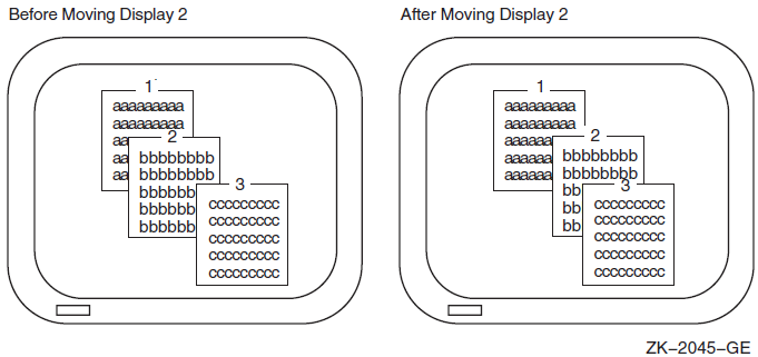
- Repasting—To repaste a display, use the SMG$REPASTE_VIRTUAL_DISPLAY routine. The following example repastes display 2. Figure 6.3, ''Repasting a Virtual Display'' shows the screen before and after the statement executes.
STATUS = SMG$REPASTE_VIRTUAL_DISPLAY (VDID,
2                                     PBID,
2                                     4,
2                                     4)
IF (.NOT. STATUS) CALL LIB$SIGNAL (%VAL(STATUS))
Figure 6.3. Repasting a Virtual Display 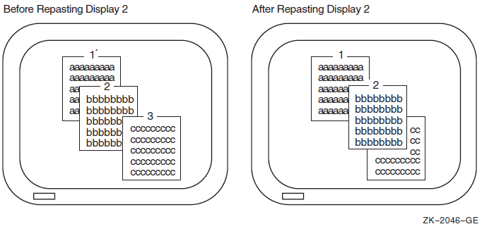
You can obtain the pasting order of the virtual displays using SMG$LIST_PASTING_ORDER. This routine returns the identifiers of all the virtual displays pasted to a specified pasteboard.
6.4.4.4. Removing Virtual Displays
- Erase a virtual display—Invoking SMG$UNPASTE_VIRTUAL_DISPLAY erases a virtual display from the screen but retains its contents in memory. The following example erases the statistics display:
STATUS = SMG$UNPASTE_VIRTUAL_DISPLAY (STATS_VDID,
2                                     PBID)
IF (.NOT. STATUS) CALL LIB$SIGNAL (%VAL (STATUS))
- Delete a virtual display—Invoking SMG$DELETE_VIRTUAL_DISPLAY removes a virtual display from the screen and removes its contents from memory. The following example deletes the statistics display:
STATUS = SMG$DELETE_VIRTUAL_DISPLAY (STATS_VDID)
IF (.NOT. STATUS) CALL LIB$SIGNAL (%VAL (STATUS))
- Delete several virtual displays—Invoking SMG$POP_VIRTUAL_DISPLAY removes a specified virtual display and any virtual displays pasted after that display from the screen and removes the contents of those displays from memory. The following example "pops" display 2. Figure 6.4, ''Popping a Virtual Display'' shows the screen before and after popping. (Note that display 3 is deleted because it was pasted after display 2, and not because it is occluding display 2).
STATUS = SMG$POP_VIRTUAL_DISPLAY (STATS_VDID,
2                                 PBID)
IF (.NOT. STATUS) CALL LIB$SIGNAL (%VAL (STATUS))
Figure 6.4. Popping a Virtual Display 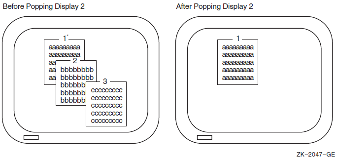
6.4.4.5. Modifying a Virtual Display
SMG$CHANGE_VIRTUAL_DISPLAY—Changes the size, video attributes, or border of a display
SMG$CHANGE_RENDITION—Changes the video attributes of a portion of a display
SMG$MOVE_TEXT—Moves text from one virtual display to another
STATUS = SMG$CHANGE_VIRTUAL_DISPLAY (WHOOPS_VDID,
2                                    5,  ! Rows
2                                    7,, ! Columns
2 0) ! Video attributes offSTATUS = SMG$CHANGE_RENDITION (STATS_VDID, 2 1, ! Row 2 1, ! Column 2 10, ! Number of rows 2 20, ! Number of columns 2 , ! Video-set argument 2 SMG$M_REVERSE) ! Video-comp argument 2
rendition-set argument of
SMG$CHANGE_RENDITION, and (3) the attributes
specified by the rendition-complement argument of
SMG$CHANGE_RENDITION. Table 6.2, ''Setting Video Attributes'' shows
the result of each possible combination.|
|
|
Result |
|---|---|---|
|
off |
off |
Uses display default |
|
on |
off |
Sets attribute |
|
off |
on |
Uses the complement of display default |
|
on |
on |
Clears attribute |
In the preceding example, the reverse video attribute is set in the
rendition-complement argument but not in the
rendition-set argument, thus specifying that
SMG$CHANGE_RENDITION use the complement of the display's
default setting to ensure that the selected portion of the display is easily seen.
Note that the resulting attributes are based on the display's default attributes, not its current attributes. If you use SMG$ routines that explicitly set video attributes, the current attributes of the display may not match its default attributes.
6.4.4.6. Using Spawned Subprocesses
SMG$CREATE_SUBPROCESS—Creates a DCL spawned subprocess and associates it with a virtual display.
- SMG$EXECUTE_COMMAND—Allows execution of a specified command in the created spawned subprocess by using mailboxes. Some restrictions apply to specifying the following commands:
SPAWN, GOTO, or LOGOUT cannot be used and will result in unpredictable results.
Single-character commands such as Ctrl/C have no effect. You can signal an end-of-file (that is, press Ctrl/Z) command by setting the
flagsargument.A dollar sign ($) must be specified as the first character of any DCL command.
SMG$DELETE_SUBPROCESS—Deletes the subprocess created by SMG$CREATE_SUBPROCESS.
6.4.5. Viewports
Viewports allow you to view different pieces of a virtual display by moving a rectangular area around on the virtual display. Only one viewport is allowed for each virtual display. Once you have associated a viewport with a virtual display, the only part of the virtual display that is viewable is contained in the viewport.
SMG$CREATE_VIEWPORT—Creates a viewport and associates it with a virtual display. You must create the virtual display first. To view the viewport, you must paste the virtual display first with SMG$PASTE_VIRTUAL_DISPLAY.
SMG$SCROLL_VIEWPORT—Scrolls the viewport within the virtual display. If you try to move the viewport outside of the virtual display, the viewport is truncated to stay within the virtual display. This routine allows you to specify the direction and extent of the scroll.
SMG$CHANGE_VIEWPORT—Moves the viewport to a new starting location and changes the size of the viewport.
SMG$DELETE_VIEWPORT—Deletes the viewport and dissociates it from the virtual display. The viewport is automatically unpasted. The virtual display associated with the viewport remains intact. You can unpaste a viewport without deleting it by using SMG$UNPASTE_VIRTUAL_DISPLAY.
6.4.6. Writing Text to Virtual Display
The SMG$ output routines allow you to write text to displays and to delete or modify the existing text of a display. Remember that changes to a virtual display are visible only if the virtual display is pasted to a pasteboard.
6.4.6.1. Positioning the Cursor
SMG$HOME_CURSOR—Moves the cursor to a corner of the virtual display. The default corner is the upper left corner, that is, row 1, column 1 of the display.
SMG$SET_CURSOR_ABS—Moves the cursor to a specified row and column.
SMG$SET_CURSOR_REL—Moves the cursor to offsets from the current cursor position. A negative value means up (rows) or left (columns). A value of 0 means no movement.
In addition, many routines permit you to specify a starting location other than the current cursor position for the operation.
The SMG$RETURN_CURSOR_POS routine returns the row and column of the current cursor position within a virtual display. You do not have to write special code to track the cursor position.
Typically, the physical cursor is at the logical cursor position of the most recently written-to display. If necessary, you can use the SMG$SET_PHYSICAL_CURSOR routine to set the physical cursor location.
6.4.6.2. Writing Data Character by Character
SMG$DRAW_CHAR—Puts one line-drawing character on the screen at a specified position. It does not change the cursor position.
SMG$PUT_CHARS—Puts one or more characters on the screen at a specified position, with the option of one video attribute.
SMG$PUT_CHARS_MULTI—Puts several characters on the screen at a specified position, with multiple video attributes.
These routines are simple and precise. They place exactly the specified characters on the screen, starting at a specified position in a virtual display. Anything currently in the positions written-to is overwritten; no other positions on the screen are affected. Convert numeric data to character data with language I/O statements before invoking SMG$PUT_CHARS.
CHARACTER*4 HOUSE_NO_STRING
INTEGER*4   HOUSE_NO,
2           LINE_NO,
2           STATS_VDID
   .
   .
   .
WRITE (UNIT=HOUSE_NO_STRING,
2      FMT='(I4)') HOUSE_NO
STATUS = SMG$PUT_CHARS (STATS_VDID,
2                       HOUSE_NO_STRING,
2                       LINE_NO,  ! Row
2                       1)        ! Column
Note that the converted integer is right-justified from column 4 because the format specification is I4 and the full character string is written. To left-justify a converted number, you must locate the first nonblank character and write a substring starting with that character and ending with the last character.
Inserting and Overwriting Text
To insert characters rather than overwrite the current contents of the screen, use the routine SMG$INSERT_CHARS. Existing characters at the location written to are shifted to the right. Characters pushed out of the display are truncated; no wrapping occurs and the cursor remains at the end of the last character inserted.
Specifying Double-Size Characters
In addition to the preceding routines, you can use SMG$PUT_CHARS_WIDE to write characters to the screen in double width or SMG$PUT_CHARS_HIGHWIDE to write characters to the screen in double height and double width. When you use these routines, you must allot two spaces for each double-width character on the line and two lines for each line of double-height characters. You cannot mix single-and double-size characters on a line.
All the character routines provide rendition-set and
rendition-complement arguments, which allow you to specify
special video attributes for the characters being written.
SMG$PUT_CHARS_MULTI allows you to specify more than one video
attribute at a time. The explanation of the SMG$CHANGE_RENDITION
routine in Section 6.4.4.5, ''Modifying a Virtual Display'' discusses how to use
rendition-set and rendition-complement
arguments.
6.4.6.3. Writing Data Line by Line
The SMG$PUT_LINE and SMG$PUT_LINE_MULTI routines write lines to virtual displays one line after another. If the display area is full, it is scrolled. You do not have to keep track of which line you are on. All routines permit you to scroll forward (up); SMG$PUT_LINE and SMG$PUT_LINE_MULTI permit you to scroll backward (down) as well. SMG$PUT_LINE permits spacing other than single spacing.
INTEGER*4     BUFF_COUNT,
2             BUFF_SIZE (4096)
CHARACTER*512 BUFF (4096)
   .
   .
   .
DO I = 1, BUFF_COUNT
  STATUS = SMG$PUT_LINE (VDID,
2                        BUFF (I) (1:BUFF_SIZE (I)))
  IF (.NOT. STATUS) CALL LIB$SIGNAL (%VAL (STATUS))
END DO
DO I = BUFF_COUNT, 1, -1
  STATUS = SMG$PUT_LINE (VDID,
2                        BUFF (I) (1:BUFF_SIZE (I)),
2                        SMG$M_DOWN)
  IF (.NOT. STATUS) CALL LIB$SIGNAL (%VAL (STATUS))
END DO
Cursor Movement and Scrolling
To maintain precise control over cursor movement and scrolling, you can write with SMG$PUT_CHARS and scroll explicitly with SMG$SCROLL_DISPLAY_AREA.SMG$PUT_CHARS leaves the cursor after the last character written and does not force scrolling; SMG$SCROLL_DISPLAY_AREA scrolls the current contents of the display forward, backward, or sideways without writing to the display. To restrict the scrolling region to a portion of the display area, use the SMG$SET_DISPLAY_SCROLL_REGION routine.
Inserting and Overwriting Text
To insert text rather than overwrite the current contents of the screen, use the SMG$INSERT_LINE routine. Existing lines are shifted up or down to open space for the new text. If the text is longer than a single line, you can specify whether or not you want the excess characters to be truncated or wrapped.
Using Double-Width Characters
In addition, you can use SMG$PUT_LINE_WIDE to write a line of text to the screen using double-width characters. You must allot two spaces for each double-width character on the line. You cannot mix single- and double-width characters on a line.
Specifying Special Video Attributes
All line routines provide rendition-set and
rendition-complement arguments, which allow you to specify
special video attributes for the text being written.
SMG$PUT_LINE_MULTI allows you to specify more than one video
attribute for the text. The explanation of the
SMG$CHANGE_RENDITION routine in Section 6.4.4.5, ''Modifying a Virtual Display'' discusses how to use the rendition-set and
rendition-complement arguments.
6.4.6.4. Drawing Lines
The routine SMG$DRAW_LINE draws solid lines on the screen. Appropriate corner and crossing marks are drawn when lines join or intersect. The routine SMG$DRAW_CHARACTER draws a single character. You can also use the routine SMG$DRAW_RECTANGLE to draw a solid rectangle. Suppose that you want to draw an object such as that shown in Figure 6.5, ''Statistics Display'' in the statistics display area (an area of 10 rows by 55 columns).

STATUS = SMG$CREATE_VIRTUAL_DISPLAY (10,
2                                    55,
2                                    STATS_VDID)
IF (.NOT. STATUS) CALL LIB$SIGNAL (%VAL (STATUS))
! Draw rectangle with upper left corner at row 1 column 1
! and lower right corner at row 10 column 55
STATUS =SMG$DRAW_RECTANGLE (STATS_VDID,
2                           1, 1,
2                           10, 55)
IF (.NOT. STATUS) CALL LIB$SIGNAL (%VAL (STATUS))
! Draw vertical lines at columns 11, 21, and 31
DO I = 11, 31, 10
  STATUS = SMG$DRAW_LINE (STATS_VDID,
2                         1, I,
2                         10, I)
  IF (.NOT. STATUS) CALL LIB$SIGNAL (%VAL (STATUS))
END DO
! Draw horizontal line at row 3
STATUS = SMG$DRAW_LINE (STATS_VDID,
2                       3, 1,
2                       3, 55)
IF (.NOT. STATUS) CALL LIB$SIGNAL (%VAL (STATUS))
STATUS = SMG$PASTE_VIRTUAL_DISPLAY (STATS_VDID,
2                                   PBID,
2                                   3,
2                                   2)
IF (.NOT. STATUS) CALL LIB$SIGNAL (%VAL (STATUS))
6.4.6.5. Deleting Text
SMG$ERASE_CHARS—Erases specified characters on one line.
SMG$ERASE_LINE—Erases the characters on one line starting from a specified position.
SMG$ERASE_DISPLAY—Erases specified characters on one or more lines.
SMG$ERASE_COLUMN—Erases a column from the specified row to the end of the column from the virtual display.
SMG$DELETE_CHARS—Deletes specified characters on one line. Any characters to the right of the deleted characters are shifted left.
SMG$DELETE_LINE—Deletes one or more full lines. Any remaining lines in the display are scrolled up to fill the empty space.
STATUS = SMG$ERASE_LINE (STATS_VDID,
2                        LINE_NO,
2                        COLUMN_NO)
IF (.NOT. STATUS) CALL LIB$SIGNAL (%VAL (STATUS))
6.4.7. Using Menus
Block menu—Selections are in matrix format. This is the type of menu often used.
Vertical menu—Each selection is on its own line.
Horizontal menu—All selections are on one line.
Menus are associated with a virtual display, and only one menu can be used for each virtual display.
SMG$CREATE_MENU—Creates a menu associated with a virtual display. This routine allows you to specify the type of menu, the position in which the menu is displayed, the format of the menu (single or double spaced), and video attributes.
SMG$SELECT_FROM_MENU—Sets up menu selection capability. You can specify a default menu selection (which is shown in reverse video), whether online help is available, a maximum time limit for making a menu selection, a key indicating read termination, whether to send the text of the menu item selected to a string, and a video attribute.
SMG$DELETE_MENU—Discontinues access to the menu and erases it.
When you are using menus, no other output should be sent to the menu area;otherwise, unpredictable results may occur.
The default SMG$SELECT_FROM_MENU allows specific operations,
such as use of the arrow keys to move up and down the menu selections, keys to make a menu
selection, ability to select more than one item at a time, ability to reselect an item
already selected, and the key sequence to invoke online help. By using the
flags argument to modify this operation, you have the option of
disallowing reselection of a menu item and of allowing any key pressed to select an
item.
6.4.8. Reading Data
You can read text from a virtual display (SMG$READ_FROM_DISPLAY) or from a virtual keyboard (SMG$READ_STRING, SMG$READ_COMPOSED_LINE, or SMG$READ_KEYSTROKE). The three routines for virtual keyboard input are known as the SMG$ input routines. SMG$READ_FROM_DISPLAY is not a true input routine because it reads text from the virtual display rather than from a user.
The SMG$ input routines can be used alone or with the SMG$ output routines. This section assumes that you are using the input routines with the output routines. Section 6.5, ''Performing Special Input/Output Actions'' describes how to use the input routines without the output routines.
When you use the SMG$ input routines with the
SMG$ output routines, always specify the optional
vdid argument of the input routine, which specifies the virtual
display in which the input is to occur. The specified virtual display must be pasted to the
device associated with the virtual keyboard that is specified as the first argument of the
input routine. The display must be pasted in column 1, cannot be occluded, and cannot have
any other display to its right; input begins at the current cursor position, but the cursor
must be in column 1.
6.4.8.1. Reading from a Display
You can read the contents of the display using the routine
SMG$READ_FROM_DISPLAY. By default, the read operation reads all
of the characters from the current cursor position to the end of that line. The
row argument of SMG$READ_FROM_DISPLAY
allows you to choose the starting point of the read operation, that is, the contents of
the specified row to the rightmost column in that row.
If the terminator-string argument is specified,
SMG$READ_FROM_DISPLAY searches backward from the current cursor
position and reads the line beginning at the first terminator
encountered (or at the beginning of the line). A terminator is a character string. You
must calculate the length of the character string read operation yourself.
CHARACTER*4 STRING
INTEGER*4   SIZE
   .
   .
   .
STATUS = SMG$HOME_CURSOR (STATS_VDID)
IF (.NOT. STATUS) CALL LIB$SIGNAL (%VAL(STATUS))
STATUS = SMG$READ_FROM_DISPLAY (STATS_VDID,
2                               STRING)
IF (.NOT. STATUS) CALL LIB$SIGNAL (%VAL(STATUS))
SIZE = 55
DO WHILE ((STRING (SIZE:SIZE) .EQ. ' ') .AND.
2         (SIZE .GT. 1))
  SIZE = SIZE - 1
END DO
6.4.8.2. Reading from a Virtual Keyboard
The SMG$CREATE_VIRTUAL_KEYBOARD routine establishes a device for input operations; the default device is the user's terminal. The routine SMG$READ_STRING reads characters typed on the screen either until the user types a terminator or until the maximum size (which defaults to 512 characters) is exceeded. (The terminator is usually a carriage return; see the routine description in the VSI OpenVMS RTL Screen Management (SMG$) Manual for a complete list of terminators). The current cursor location for the display determines where the read operation begins.
The operating system's terminal driver processes carriage returns differently than the SMG$routines. Therefore, in order to scroll input accurately, you must keep track of your vertical position in the display area. Explicitly set the cursor position and scroll the display. If a read operation takes place on a row other than the last row of the display, advance the cursor to the beginning of the next row before the next operation. If a read operation takes place on the last row of the display, scroll the display with SMG$SCROLL_DISPLAY_AREA and then set the cursor to the beginning of the row. Modify the read operation with TRM$M_TM_NOTRMECHO to ensure that no extraneous scrolling occurs.
   .
   .
   .
! Read first record
STATUS = SMG$HOME_CURSOR (VDID)
IF (.NOT. STATUS) CALL LIB$SIGNAL (%VAL (STATUS))
STATUS = SMG$READ_STRING (KBID,
2                         TEXT,
2                         'Prompt: ',
2                         4,
2                         TRM$M_TM_TRMNOECHO,,,
2                         TEXT_SIZE,,
2                         VDID)
! Read remaining records until CTRL/Z
DO WHILE (STATUS .NE. SMG$_EOF)
  IF (.NOT. STATUS) CALL LIB$SIGNAL (%VAL (STATUS))
  ! Process record
   .
   .
   .
  ! Set up screen for next read
  ! Display area contains four rows
  STATUS = SMG$RETURN_CURSOR_POS (VDID, ROW, COL)
  IF (.NOT. STATUS) CALL LIB$SIGNAL (%VAL (STATUS))
  IF (ROW .EQ. 4) THEN
    STATUS = SMG$SCROLL_DISPLAY_AREA (VDID)
    IF (.NOT. STATUS) CALL LIB$SIGNAL (%VAL (STATUS))
    STATUS = SMG$SET_CURSOR_ABS (VDID, 4, 1)
    IF (.NOT. STATUS) CALL LIB$SIGNAL (%VAL (STATUS))
  ELSE
    STATUS = SMG$SET_CURSOR_ABS (VDID,, 1)
    IF (.NOT. STATUS) CALL LIB$SIGNAL (%VAL (STATUS))
    STATUS = SMG$SET_CURSOR_REL (VDID, 1)
    IF (.NOT. STATUS) CALL LIB$SIGNAL (%VAL (STATUS))
  END IF
  ! Read next record
  STATUS = SMG$READ_STRING (KBID,
2                           TEXT,
2                           'Prompt: ',
2                           4,
2                           TRM$M_TM_TRMNOECHO,,,
2                           TEXT_SIZE,,
2                           VDID)
END DO
Note
Because you are controlling the scrolling, SMG$PUT_LINE and SMG$PUT_LINE_MULTI might not scroll as expected. When scrolling a mix of input and output, you can prevent problems by using SMG$PUT_CHARS.
6.4.8.3. Reading from the Keypad
To read from the keypad in keypad mode (that is, pressing a keypad character to perform some special action rather than entering data), modify the read operation with TRM$M_TM_ESCAPE and TRM$M_TM_NOECHO. Examine the terminator to determine which key was pressed.
Example 6.11, ''Reading Data from the Keypad'' moves the cursor on the screen in response to the user's pressing the keys surrounding the keypad 5 key. The keypad 8 key moves the cursor north (up); the keypad 9 key moves the cursor northeast; the keypad 6 key moves the cursor east (right); and so on. The SMG$SET_CURSOR_REL routine is called, instead of being invoked as a function, because you do not want to abort the program on an error. (The error attempts to move the cursor out of the display area and, if this error occurs, you do not want the cursor to move.) The read operation is also modified with TRM$M_TM_PURGE to prevent the user from getting ahead of the cursor.
   .
   .
   .
INTEGER STATUS,
2       PBID,
2       ROWS,
2       COLUMNS,
2       VDID,     ! Virtual display ID
2       KID,      ! Keyboard ID
2       SMG$CREATE_PASTEBOARD,
2       SMG$CREATE_VIRTUAL_DISPLAY,
2       SMG$CREATE_VIRTUAL_KEYBOARD,
2       SMG$PASTE_VIRTUAL_DISPLAY,
2       SMG$HOME_CURSOR,
2       SMG$SET_CURSOR_REL,
2       SMG$READ_STRING,
2       SMG$ERASE_PASTEBOARD,
2       SMG$PUT_CHARS,
2       SMG$READ_FROM_DISPLAY
CHARACTER*31 INPUT_STRING,
2            MENU_STRING
INTEGER*2    TERMINATOR
INTEGER*4    MODIFIERS
INCLUDE '($SMGDEF)'
INCLUDE '($TRMDEF)'
! Set up screen and keyboard
STATUS = SMG$CREATE_PASTEBOARD (PBID,
2                               'SYS$OUTPUT',
2                               ROWS,
2                               COLUMNS)
IF (.NOT. STATUS) CALL LIB$SIGNAL (%VAL (STATUS))
STATUS = SMG$CREATE_VIRTUAL_DISPLAY (ROWS,
2                                    COLUMNS,
2                                    VDID)
IF (.NOT. STATUS) CALL LIB$SIGNAL (%VAL (STATUS))
STATUS = SMG$PUT_CHARS (VDID,
2                       '__ MENU CHOICE ONE',
2                       10,30)
IF (.NOT. STATUS) CALL LIB$SIGNAL (%VAL (STATUS))
STATUS = SMG$PUT_CHARS (VDID,
2                       '__ MENU CHOICE TWO',
2                       15,30)
IF (.NOT. STATUS) CALL LIB$SIGNAL (%VAL (STATUS))
STATUS = SMG$CREATE_VIRTUAL_KEYBOARD (KID)
IF (.NOT. STATUS) CALL LIB$SIGNAL (%VAL (STATUS))
STATUS = SMG$PASTE_VIRTUAL_DISPLAY (VDID,
2                                   PBID,
2                                   1,
2                                   1)
IF (.NOT. STATUS) CALL LIB$SIGNAL (%VAL (STATUS))
! Put cursor in NW corner
STATUS = SMG$HOME_CURSOR (VDID)
IF (.NOT. STATUS) CALL LIB$SIGNAL (%VAL (STATUS))
! Read character from keyboard
MODIFIERS = TRM$M_TM_ESCAPE .OR.
2           TRM$M_TM_NOECHO .OR.
2           TRM$M_TM_PURGE
STATUS = SMG$READ_STRING (KID,
2                         INPUT_STRING,
2                         ,
2                         6,
2                         MODIFIERS,
2                         ,
2                         ,
2                         ,
2                         TERMINATOR)
DO WHILE ((STATUS) .AND.
2         (TERMINATOR .NE. SMG$K_TRM_CR))
  ! Check status of last read
  IF (.NOT. STATUS) CALL LIB$SIGNAL (%VAL (STATUS))
  ! North
  IF (TERMINATOR .EQ. SMG$K_TRM_KP8) THEN
    CALL SMG$SET_CURSOR_REL (VDID, -1, 0)
  ! Northeast
  ELSE IF (TERMINATOR .EQ. SMG$K_TRM_KP9) THEN
    CALL SMG$SET_CURSOR_REL (VDID, -1, 1)
  ! Northwest
  ELSE IF (TERMINATOR .EQ. SMG$K_TRM_KP7) THEN
    CALL SMG$SET_CURSOR_REL (VDID, -1, -1)
  ! South
  ELSE IF (TERMINATOR .EQ. SMG$K_TRM_KP2) THEN
    CALL SMG$SET_CURSOR_REL (VDID, 1, 0)
  ! Southeast
  ELSE IF (TERMINATOR .EQ. SMG$K_TRM_KP3) THEN
    CALL SMG$SET_CURSOR_REL (VDID, 1, 1)
  ! Southwest
  ELSE IF (TERMINATOR .EQ. SMG$K_TRM_KP1) THEN
    CALL SMG$SET_CURSOR_REL (VDID, 1, -1)
  ! East
  ELSE IF (TERMINATOR .EQ. SMG$K_TRM_KP6) THEN
    CALL SMG$SET_CURSOR_REL (VDID, 0, 1)
  ! West
  ELSE IF (TERMINATOR .EQ. SMG$K_TRM_KP4) THEN
    CALL SMG$SET_CURSOR_REL (VDID, 0, -1)
  END IF
  ! Read another character
  STATUS = SMG$READ_STRING (KID,
2                           INPUT_STRING,
2                           ,
2                           6,
2                           MODIFIERS,
2                           ,
2                           ,
2                           ,
2                           TERMINATOR)
END DO
! Read menu entry and process
!
STATUS = SMG$READ_FROM_DISPLAY (VDID,
2                               MENU_STRING)
IF (.NOT. STATUS) CALL LIB$SIGNAL (%VAL (STATUS))
   .
   .
   .
! Clear screen
STATUS = SMG$ERASE_PASTEBOARD (PBID)
IF (.NOT. STATUS) CALL LIB$SIGNAL (%VAL (STATUS))

END
6.4.8.4. Reading Composed Input
If states—You can define the same key to mean different things indifferent states. You can define a key to cause a change in state. The change in state can be temporary (until after the next defined key is pressed) or permanent (until a key that changes states is pressed).
Input termination—You can define the key to cause termination of the input transmission (as if the Return key were pressed after the character string). If the key is not defined to cause termination of the input, the user must press a terminator or another key that does cause termination.
INTEGER*4 TABLEID
   .
   .
   .
! Create table for key definitions
STATUS = SMG$CREATE_KEY_TABLE (TABLEID)
IF (.NOT. STATUS) CALL LIB$SIGNAL (%VAL (STATUS))
! Load table
! If user presses PF1, the state changes to BYTEN
! The BYTEN state is in effect only for the very next key
STATUS = SMG$ADD_KEY_DEF (TABLEID,
2                         'PF1',
2                         ,,,'BYTEN')
IF (.NOT. STATUS) CALL LIB$SIGNAL (%VAL (STATUS))
! Pressing KP1 through Kp9 in the null state is like typing
! 1000 through 9000 and pressing return
STATUS = SMG$ADD_KEY_DEF (TABLEID,
2                         'KP1',
2                         ,
2                         SMG$M_KEY_TERMINATE,
2                         '1000')
IF (.NOT. STATUS) CALL LIB$SIGNAL (%VAL (STATUS))
STATUS = SMG$ADD_KEY_DEF (TABLEID,
2                         'KP2',
2                         ,
2                         SMG$M_KEY_TERMINATE,
2                         '2000')
IF (.NOT. STATUS) CALL LIB$SIGNAL (%VAL (STATUS))
   .
   .
   .
STATUS = SMG$ADD_KEY_DEF (TABLEID,
2                         'KP9',
2                         ,
2                         SMG$M_KEY_TERMINATE,
2                         '9000')
IF (.NOT. STATUS) CALL LIB$SIGNAL (%VAL (STATUS))
! Pressing KP1 through KP9 in the BYTEN state is like
! typing 10000 through 90000 and pressing return
STATUS = SMG$ADD_KEY_DEF (TABLEID,
2                         'KP1',
2                         'BYTEN',
2                         SMG$M_KEY_TERMINATE,
2                         '10000')
IF (.NOT. STATUS) CALL LIB$SIGNAL (%VAL (STATUS))
STATUS = SMG$ADD_KEY_DEF (TABLEID,
2                         'KP2',
2                         'BYTEN',
2                         SMG$M_KEY_TERMINATE,
2                         '20000')
IF (.NOT. STATUS) CALL LIB$SIGNAL (%VAL (STATUS))
   .
   .
   .
STATUS = SMG$ADD_KEY_DEF (TABLEID,
2                         'KP9',
2                         'BYTEN',
2                         SMG$M_KEY_TERMINATE,
2                         '90000')
IF (.NOT. STATUS) CALL LIB$SIGNAL (%VAL (STATUS))
! End loading key definition table
   .
   .
   .
! Read input which substitutes key definitions where appropriate
STATUS = SMG$READ_COMPOSED_LINE (KBID,
2                                TABLEID,
2                                STRING,
2                                SIZE,
2                                VDID)
IF (.NOT. STATUS) CALL LIB$SIGNAL (%VAL (STATUS))
   .
   .
   .
Use the SMG$DELETE_KEY_DEF routine to delete a key definition; use the SMG$GET_KEY_DEF routine to examine a key definition. You can also load key definition tables with the SMG$DEFINE_KEY and SMG$LOAD_KEY_DEFS routines; use the DCL command DEFINE/KEY to specify input to these routines.
To use keypad keys 0 through 9, the keypad must be in application mode. For details, see SMG$SET_KEYPAD_MODE in the VSI OpenVMS RTL Screen Management (SMG$) Manual.
6.4.9. Controlling Screen Updates
If your program needs to make a number of changes to a virtual display, you can use SMG$ routines to make all of the changes before updating the display. The SMG$BEGIN_DISPLAY_UPDATE routine causes output operations to a pasted display to be reflected only in the display's buffers. The SMG$END_DISPLAY_UPDATE routine writes the display's buffer to the pasteboard.
The SMG$BEGIN_DISPLAY_UPDATE and SMG$END_DISPLAY_UPDATE routines increment and decrement a counter. When this counter's value is 0, output to the virtual display is sent to the pasteboard immediately. The counter mechanism allows a subroutine to request and turn off batching without disturbing the batching state of the calling program.
A second set of routines, SMG$BEGIN_PASTEBOARD_UPDATE and SMG$END_PASTEBOARD_UPDATE, allow you to buffer output to a pasteboard in asimilar manner.
6.4.10. Maintaining Modularity
Mixing SMG I/O and other forms of I/O
In general, do not use any other form of terminal I/O while the terminal is active as a pasteboard. If you do use I/O other than SMG I/O (for example, if you invoke a subprogram that may perform non-SMG terminal I/O), first invoke the SMG$SAVE_PHYSICAL_SCREEN routine and when the non-SMG I/O completes, invoke the SMG$RESTORE_PHYSICAL_SCREEN routine, as demonstrated in the following example:STATUS = SMG$SAVE_PHYSICAL_SCREEN (PBID, 2 SAVE_VDID) IF (.NOT. STATUS) CALL LIB$SIGNAL (%VAL (STATUS)) CALL GET_EXTRA_INFO (INFO_ARRAY) STATUS = SMG$RESTORE_PHYSICAL_SCREEN (PBID, 2 SAVE_VDID) IF (.NOT. STATUS) CALL LIB$SIGNAL (%VAL (STATUS))
Sharing the pasteboard
A routine using the terminal screen without consideration for its current contents must use the existing pasteboard ID associated with the terminal and delete any virtual displays it creates before returning control to the high-level code. This guideline also applies to the program unit that invokes a subprogram that also performs screen I/O. The safest way to clean up your virtual displays is to call the SMG$POP_VIRTUAL_DISPLAY routine and name the first virtual display you created. The following example invokes a subprogram that uses the terminal screen:
Invoking Program Unit
CALL GET_EXTRA_INFO (PBID,
2                    INFO_ARRAY)
   .
   .
   .
CALL STATUS = SMG$CREATE_PASTEBOARD (PBID)
IF (.NOT. STATUS) CALL LIB$SIGNAL (%VAL (STATUS))
Subprogram
SUBROUTINE GET_EXTRA_INFO (PBID,
2                          INFO_ARRAY)
   .
   .
   .
! Start executable code
STATUS = SMG$CREATE_VIRTUAL_DISPLAY (4,
2                                    40,
2                                    INSTR_VDID)
IF (.NOT. STATUS) CALL LIB$SIGNAL (%VAL (STATUS))
STATUS = SMG$PASTE_VIRTUAL_DISPLAY (INSTR_VDID,
2                                   PBID, 1, 1)
IF (.NOT. STATUS) CALL LIB$SIGNAL (%VAL (STATUS))
   .
   .
   .
STATUS = SMG$POP_VIRTUAL_DISPLAY (INSTR_VDID,
2                                 PBID)
IF (.NOT. STATUS) CALL LIB$SIGNAL (%VAL (STATUS))

END
Sharing virtual displays
To share a virtual display created by high-level code, the low-level code must use the virtual display ID created by the high-level code; an invoking program unit must pass the virtual display ID to the subprogram. To share a virtual display created by low-level code, the high-level code must use the virtual display ID created by the low-level code; a subprogram must return the virtual display ID to the invoking program.
The following example permits a subprogram to use a virtual display created by the invoking program unit:
Invoking Program Unit
STATUS = SMG$CREATE_VIRTUAL_DISPLAY (4,
2                                    40,
2                                    INSTR_VDID)
IF (.NOT. STATUS) CALL LIB$SIGNAL (%VAL (STATUS))
STATUS = SMG$PASTE_VIRTUAL_DISPLAY (INSTR_VDID,
2                                   PBID, 1, 1)
IF (.NOT. STATUS) CALL LIB$SIGNAL (%VAL (STATUS))
CALL GET_EXTRA_INFO (PBID,
2                    INSTR_VDID)
IF (.NOT. STATUS) CALL LIB$SIGNAL (%VAL (STATUS))
Subprogram
SUBROUTINE GET_EXTRA_INFO (PBID,
2                          INSTR_VDID)
6.5. Performing Special Input/Output Actions
Screen management input routines and the SYS$QIO and SYS$QIOW system services allow you to perform I/O operations otherwise unavailable to high-level languages. For example, you can allow a user to interrupt normal program execution by typing a character and by providing a mechanism for reading that character. You can also control such things as echoing, time allowed for input, and whether data is read from the type-ahead buffer.
Some of the operations described in the following sections require the use of the SYS$QIO or SYS$QIOW system services. For more information about the QIO system services, see the VSI OpenVMS System Services Reference Manual and Chapter 7, "System Service Input/Output Operations".
Call SMG$CREATE_VIRTUAL_KEYBOARD to associate a logical keyboard with a device or file specification (SYS$INPUT by default). SMG$CREATE_VIRTUAL_KEYBOARD returns a keyboard identification number; use that number to identify the device or file to the SMG$ input routines.
Call an SMG$ input routine (SMG$READ_STRING or SMG$READ_COMPOSED_LINE) to read data typed at the device associated with the virtual keyboard.
When using the SMG$ input routines without the SMG$ output routines, do not specify the optional VDID argument of the input routine.
6.5.1. Using Ctrl/C and Ctrl/Y Interrupts
Queue an asynchronous system trap (AST)—Issue the SYS$QIO or SYS$QIOW system service with a function code of IO$_SETMODE modified by either IO$M_CTRLCAST (for Ctrl/C interrupts) or IO$M_CTRLYAST (for Ctrl/Y interrupts). For the
P1argument, provide the name of a subroutine to be executed when the interrupt occurs. For theP2argument, you can optionally identify one longword argument to pass to the AST subroutine.Write an AST subroutine—Write the subroutine identified in the
P1argument of the QIO system service and link the subroutine into your program. Your subroutine can take one longword dummy argument to be associated with theP2argument in the QIO system service. You must define common areas to access any other data in your program from the AST routine.
ASTs are asynchronous—Since your AST subroutine does not know exactly where you are in your program when the interrupt occurs, you should avoid manipulating data or performing other mainline activities. In general, the AST subroutine should either notify the mainline code (for example, by setting a flag) that the interrupt occurred, or clean up and exit from the program (if that is what you want to do).
ASTs need new channels to the terminal—If you try to access the terminal with language I/O statements using SYS$INPUT or SYS$OUTPUT, you may receive a redundant I/O error. You must establish another channel to the terminal by explicitly opening the terminal.
Ctrl/C and Ctrl/Y ASTs are one-time ASTs—After a Ctrl/C or Ctrl/Y AST is delivered, it is dequeued. You must reissue the QIO system service if you wish to trap another interrupt.
Many ASTs can be queued—You can queue multiple ASTs (for the same or different AST subroutines, on the same or different channels) by issuing the appropriate number of QIO system services. The system delivers the ASTs on a last-in, first-out (LIFO) basis.
Unhandled Ctrl/Cs turn into Ctrl/Ys—If the user enters Ctrl/C and you do not have an AST queued to handle the interrupt, the system turns the Ctrl/C interrupt into a Ctrl/Y interrupt.
- DCL handles Ctrl/Y interrupts—DCL handles Ctrl/Y interrupts by returning the user to DCL command level, where the user has the option of continuing or exiting from your program. DCL takes precedence over your AST subroutine for Ctrl/Y interrupts. Your Ctrl/Y AST subroutine is executed only under the following circumstances:
If Ctrl/Y interrupts are disabled at DCL level (SETNOCONTROL_Y) before your program is executed
If your program disables DCL Ctrl/Y interrupts with LIB$DISABLE_CTRL
If the user elects to continue your program after DCL interrupts it
You can dequeue Ctrl/C and Ctrl/Y ASTs—You can dequeue all Ctrl/C or Ctrl/Y ASTs on a channel by issuing the appropriate QIO system service with a value of 0 for the
P1argument (passed by immediate value). You can dequeue all Ctrl/C ASTs on a channel by issuing the SYS$CANCEL system service for the appropriate channel. You can dequeue all Ctrl/Y ASTs on a channel by issuing the SYS$DASSGN system service for the appropriate channel.You can use SMG$ routines—You can connect to the terminal using the SMG$routines from either AST level or mainline code. Do not attempt to connect to the terminal from AST level if you do so in your mainline code.
!Main Program
   .
   .
   .
INTEGER STATUS
! Accumulated data records
CHARACTER*132 STORAGE (255)
INTEGER*4     STORAGE_SIZE (255),
2             STORAGE_COUNT
! QIOW and QIO structures
INTEGER*2 INPUT_CHAN
INTEGER*4 CODE
STRUCTURE /IOSTAT_BLOCK/
  INTEGER*2 IOSTAT
  BYTE      TRANSMIT,
2           RECEIVE,
2           CRFILL,
2           LFFILL,
2           PARITY,
2           ZERO
END STRUCTURE
RECORD /IOSTAT_BLOCK/ IOSB
! Flag to notify program of CTRL/C interrupt
LOGICAL*4 CTRLC_CALLED
! AST subroutine to handle CTRL/C interrupt
EXTERNAL CTRLC_AST
! Subroutines
INTEGER SYS$ASSIGN,
2       SYS$QIOW
! Symbols used for I/O operations
INCLUDE '($IODEF)'
! Put values into array
CALL LOAD_STORAGE (STORAGE,
2                  STORAGE_SIZE,
2                  STORAGE_COUNT)
! Assign channel and set up QIOW structures
STATUS = SYS$ASSIGN ('SYS$INPUT',
2                    INPUT_CHAN,,)
IF (.NOT. STATUS) CALL LIB$SIGNAL (%VAL (STATUS))
CODE = IO$_SETMODE .OR. IO$M_CTRLCAST
! Queue an AST to handle CTRL/C interrupt
STATUS = SYS$QIOW (,
2                  %VAL (INPUT_CHAN),
2                  %VAL (CODE),
2                  IOSB,
2                  ,,
2                  CTRLC_AST,    ! Name of AST routine
2                  CTRLC_CALLED, ! Argument for AST routine
2                  ,,,)
IF (.NOT. STATUS) CALL LIB$SIGNAL (%VAL (STATUS))
IF (.NOT. IOSB.IOSTAT)
2  CALL LIB$SIGNAL (%VAL (IOSB.IOSTAT))
! Display STORAGE array, one element per line
DO I = 1, STORAGE_COUNT
  TYPE *, STORAGE (I) (1:STORAGE_SIZE (I))

  ! Additional actions if user types CTRL/C
  IF (CTRLC_CALLED) THEN
    CTRLC_CALLED = .FALSE.
    ! Show user number of lines displayed so far
    TYPE *, 'Number of lines: ', I
    ! Requeue AST
    STATUS = SYS$QIOW (,
2                      %VAL (INPUT_CHAN),
2                      %VAL (CODE),
2                      IOSB,
2                      ,,
2                      CTRLC_AST,
2                      CTRLC_CALLED,
2                      ,,,)
    IF (.NOT. STATUS) CALL LIB$SIGNAL (%VAL (STATUS))
    IF (.NOT. IOSB.IOSTAT)
2      CALL LIB$SIGNAL (%VAL (IOSB.IOSTAT))
  END IF
END DO

END
AST Routine
! AST routine
! Notifies program that user typed CTRL/C
SUBROUTINE CTRLC_AST (CTRLC_CALLED)
LOGICAL*4 CTRLC_CALLED
CTRLC_CALLED = .TRUE.

END
6.5.2. Detecting Unsolicited Input
You can detect input from the terminal even if you have not called SMG$READ_COMPOSED_LINE or SMG$READ_STRING by using SMG$ENABLE_UNSOLICITED_INPUT. This routine uses the AST mechanism to transfer control to a subprogram of your choice each time the user types at the terminal; the AST subprogram is responsible for reading any input. When the subprogram completes, control returns to the point in your mainline code where it was interrupted.
The SMG$ENABLE_UNSOLICITED_INPUT routine is not an SMG$ input routine. Before invoking SMG$ENABLE_UNSOLICITED_INPUT, you must invoke SMG$CREATE_PASTEBOARD to associate a pasteboard with the terminal and SMG$CREATE_VIRTUAL_KEYBOARD to associate a virtual keyboard with the same terminal.
The pasteboard identification number (use the value returned by SMG$CREATE_PASTEBOARD)
The name of an AST subprogram
An argument to be passed to the AST subprogram
When SMG$ENABLE_UNSOLICITED_INPUT invokes the AST subprogram, it passes two arguments to the subprogram: the pasteboard identification number and the argument that you specified. Typically, you write the AST subprogram to read the unsolicited input with SMG$READ_STRING. Since SMG$READ_STRING requires that you specify the virtual keyboard at which the input was typed, specify the virtual keyboard identification number as the second argument to pass to the AST subprogram.
! Main Program
! The main program calls DISPLAY_ARRAY once for each array.
! DISPLAY_ARRAY displays the array in a DO loop.
! If the user enters input from the terminal, the loop is
! interrupted and the AST routine takes over.
! If the user types anything beginning with an N, the AST
! sets DO_NEXT and resumes execution -- DISPLAY_ARRAY drops
! out of the loop processing the array (because DO_NEXT is
! set -- and the main program calls DISPLAY_ARRAY for the
! next array.
! If the user types anything not beginning with an N,
! the program exits.
   .
   .
   .
INTEGER*4 STATUS,
2         VKID,  ! Virtual keyboard ID
2         PBID   ! Pasteboard ID
! Storage arrays
INTEGER*4 ARRAY1 (256),
2         ARRAY2 (256),
2         ARRAY3 (256)
! System routines
INTEGER*4 SMG$CREATE_PASTEBOARD,
2         SMG$CREATE_VIRTUAL_KEYBOARD,
2         SMG$ENABLE_UNSOLICITED_INPUT
! AST routine
EXTERNAL  AST_ROUTINE
! Create a pasteboard
STATUS = SMG$CREATE_PASTEBOARD (PBID,        ! Pasteboard ID
2                               'SYS$INPUT')
IF (.NOT. STATUS) CALL LIB$SIGNAL (%VAL (STATUS))
! Create a keyboard for the same device
STATUS = SMG$CREATE_VIRTUAL_KEYBOARD (VKID,  ! Keyboard ID
2                                     'SYS$INPUT')
IF (.NOT. STATUS) CALL LIB$SIGNAL (%VAL (STATUS))
! Enable unsolicited input
STATUS = SMG$ENABLE_UNSOLICITED_INPUT (PBID, ! Pasteboard ID
2                                      AST_ROUTINE,
2                                      VKID) ! Pass keyboard
                                             ! ID to AST
IF (.NOT. STATUS) CALL LIB$SIGNAL (%VAL (STATUS))
   .
   .
   .
! Call display subroutine once for each array
CALL DISPLAY_ARRAY (ARRAY1)
CALL DISPLAY_ARRAY (ARRAY2)
CALL DISPLAY_ARRAY (ARRAY3)

END
Array Display Routine
! Subroutine to display one array
SUBROUTINE DISPLAY_ARRAY (ARRAY)
! Dummy argument
INTEGER*4 ARRAY (256)
! Status
INTEGER*4 STATUS
! Flag for doing next array
LOGICAL*4 DO_NEXT
COMMON /DO_NEXT/ DO_NEXT
! If AST has been delivered, reset
IF (DO_NEXT) DO_NEXT = .FALSE.
! Initialize control variable
I = 1
! Display entire array unless interrupted by user
! If interrupted by user (DO_NEXT is set), drop out of loop
DO WHILE ((I .LE. 256) .AND. (.NOT. DO_NEXT))
  TYPE *, ARRAY (I)
  I = I + 1
END DO

END
AST Routine
! Subroutine to read unsolicited input
SUBROUTINE AST_ROUTINE (PBID,
2                       VKID)
! dummy arguments
INTEGER*4 PBID,                  ! Pasteboard ID
2         VKID                   ! Keyboard ID
! Status
INTEGER*4 STATUS
! Flag for doing next array
LOGICAL*4 DO_NEXT
COMMON /DO_NEXT/ DO_NEXT
! Input string
CHARACTER*4 INPUT
! Routines
INTEGER*4 SMG$READ_STRING
! Read input
STATUS = SMG$READ_STRING (VKID,  ! Keyboard ID
2                         INPUT)
IF (.NOT. STATUS) CALL LIB$SIGNAL (%VAL (STATUS))
! If user types anything beginning with N, set DO_NEXT
! otherwise, exit from program
IF (INPUT (1:1) .EQ. 'N') THEN
  DO_NEXT = .TRUE.
ELSE
  CALL EXIT
END IF

END
6.5.3. Using the Type-Ahead Buffer
Normally, if the user types at the terminal before your application is able to read from that device, the input is saved in a special data structure maintained by the system called the type-ahead buffer. When your application is ready to read from the terminal, the input is transferred from the type-ahead buffer to your input buffer. The type-ahead buffer is preset at a size of 78 bytes. If the HOSTSYNC characteristic is on (the usual condition), input to the type-ahead buffer is stopped (the keyboard locks) when the buffer is within 8 bytes of being full. If the HOSTSYNC characteristic is off, the bell rings when the type-ahead buffer is within 8 bytes of being full; if you overflow the buffer, the excess data is lost. The TTY_ALTALARM system parameter determines the point at which either input is stopped or the bell rings.
modifiers argument.
Clearing the type-ahead buffer has the effect of reading only what the user types on the
terminal after the read operation is invoked. Any characters in the type-ahead buffer are
lost. The following example illustrates how to purge the type-ahead
buffer:INTEGER*4 SMG$CREATE_VIRTUAL_KEYBOARD, 2 SMG$READ_STRING, 2 STATUS, 2 VKID, ! Virtual keyboard ID 2 INPUT_SIZE CHARACTER*512 INPUT INCLUDE '($TRMDEF)' STATUS = SMG$CREATE_VIRTUAL_KEYBOARD (VKID, 2 'SYS$INPUT') ! I/O device IF (.NOT. STATUS) CALL LIB$SIGNAL (%VAL (STATUS)) STATUS = SMG$READ_STRING (VKID, ! Keyboard ID 2 INPUT, ! Data read 2 'Prompt> ', 2 512, 2 TRM$M_TM_PURGE, 2 ,, 2 INPUT_SIZE) IF (.NOT. STATUS) CALL LIB$SIGNAL (%VAL (STATUS))
You can also clear the type-ahead buffer with a QIO read operation modified by IO$M_PURGE (defined in $IODEF). You can turn off the type-ahead buffer for further read operations with a QIO set mode operation that specifies TT$M_NOTYPEAHD as a basic terminal characteristic.
You can examine the type-ahead buffer by issuing a QIO sense mode operation modified by
IO$M_TYPEAHDCNT. The number of characters in the type-ahead
buffer and the value of the first character are returned to the P1
argument.
The size of the type-ahead buffer is determined by the TTY_TYPAHDSZ system parameter. You can specify an alternative type-ahead buffer by turning on the ALTYPEAHD terminal characteristic; the size of the alternative type-ahead buffer is determined by the TTY_ALTYPAHD system parameter.
6.5.4. Using Echo
Normally, the system writes back to the terminal any printable characters that the user types at that terminal. The system also writes highlighted words in response to certain control characters; for example, the system writes EXIT if the user enters Ctrl/Z. If the user types ahead of your read, the characters are not echoed until you read them from the type-ahead buffer.
modifiers argument.
You can turn off echoing for control characters only by modifying the read operation with
TRM$M_TM_TRMNOECHO. The following example turns off all echoing
for the read
operation:INTEGER*4 SMG$CREATE_VIRTUAL_KEYBOARD, 2 SMG$READ_STRING, 2 STATUS, 2 VKID, ! Virtual keyboard ID 2 INPUT_SIZE CHARACTER*512 INPUT INCLUDE '($TRMDEF)' STATUS = SMG$CREATE_VIRTUAL_KEYBOARD (VKID, ! Keyboard ID 2 'SYS$INPUT') ! I/O device IF (.NOT. STATUS) CALL LIB$SIGNAL (%VAL (STATUS)) STATUS = SMG$READ_STRING (VKID, ! Keyboard ID 2 INPUT, ! Data read 2 'Prompt> ', 2 512, 2 TRM$M_TM_NOECHO, 2 ,, 2 INPUT_SIZE) IF (.NOT. STATUS) CALL LIB$SIGNAL (%VAL (STATUS))
You can also turn off echoing with a QIO read operation modified by IO$M_NOECHO (defined in $IODEF). You can turn off echoing for further read operations with a QIO set mode operation that specifies TT$M_NOECHO as a basic terminal characteristic.
6.5.5. Using Timeout
timeout argument, the number of
seconds the user has to respond. If the user fails to type a character in the allotted time,
the error condition SS$_TIMEOUT (defined in
$SSDEF) is returned. The following example restricts the user to
8 seconds in which to respond to a read
command:INTEGER*4 SMG$CREATE_VIRTUAL_KEYBOARD, 2 SMG$READ_STRING, 2 STATUS, 2 VKID, ! Virtual keyboard ID 2 INPUT_SIZE CHARACTER*512 INPUT INCLUDE '($SSDEF)' STATUS = SMG$CREATE_VIRTUAL_KEYBOARD (VKID, 2 'SYS$INPUT') IF (.NOT. STATUS) CALL LIB$SIGNAL (%VAL (STATUS)) STATUS = SMG$READ_STRING (VKID, ! Keyboard ID 2 INPUT, ! Data read 2 'Prompt> ', 2 512, 2 , 2 8, 2 , 2 INPUT_SIZE) IF (.NOT. STATUS) THEN IF (STATUS .EQ. SS$_TIMEOUT) CALL NO_RESPONSE () ELSE CALL LIB$SIGNAL (%VAL (STATUS)) END IF
You can cause a QIO read operation to time out after a certain number of seconds by modifying
the operation with IO$M_TIMED and by specifying the number of seconds in the
P3 argument. A message broadcast to a terminal resets a timer that
is set for a timed read operation (regardless of whether the operation was initiated with
QIO or SMG).
Note that the timed read operations work on a character-by-character basis. To set a time limit on an input record rather than an input character, you must use the SYS$SETIMR system service. The SYS$SETIMR executes an AST routine at a specified time. The specified time is the input time limit. When the specified time is reached, the AST routine cancels any outstanding I/O on the channel that is assigned to the user's terminal.
6.5.6. Converting Lowercase to Uppercase
modifiers argument,
as shown in the following
example:INTEGER*4 SMG$CREATE_VIRTUAL_KEYBOARD, 2 SMG$READ_STRING, 2 STATUS, 2 VKID, ! Virtual keyboard ID 2 INPUT_SIZE CHARACTER*512 INPUT INCLUDE '($TRMDEF)' STATUS = SMG$CREATE_VIRTUAL_KEYBOARD (VKID, ! Keyboard ID 2 'SYS$INPUT') IF (.NOT. STATUS) CALL LIB$SIGNAL (%VAL (STATUS)) STATUS = SMG$READ_STRING (VKID, ! Keyboard ID 2 INPUT, ! Data read 2 'Prompt> ', 2 512, 2 TRM$M_TM_CVTLOW, 2 ,, 2 INPUT_SIZE) IF (.NOT. STATUS) CALL LIB$SIGNAL (%VAL (STATUS))
You can also convert lowercase characters to uppercase with a QIO read operation modified by IO$M_CVTLOW (defined in $IODEF).
6.5.7. Performing Line Editing and Control Actions
modifiers
argument. The following example shows how you can inhibit line
editing:INTEGER*4 SMG$CREATE_VIRTUAL_KEYBOARD, 2 SMG$READ_STRING, 2 STATUS, 2 VKID, ! Virtual keyboard ID 2 INPUT_SIZE CHARACTER*512 INPUT INCLUDE '($TRMDEF)' STATUS = SMG$CREATE_VIRTUAL_KEYBOARD (VKID, ! Keyboard ID 2 'SYS$INPUT') IF (.NOT. STATUS) CALL LIB$SIGNAL (%VAL (STATUS)) STATUS = SMG$READ_STRING (VKID, ! Keyboard ID 2 INPUT, ! Data read 2 'Prompt> ', 2 512, 2 TRM$M_TM_NOFILTR, 2 ,, 2 INPUT_SIZE) IF (.NOT. STATUS) CALL LIB$SIGNAL (%VAL (STATUS))
You can also inhibit line editing with a QIO read operation modified by IO$M_NOFILTR (defined in $IODEF).
6.5.8. Using Broadcasts
INTEGER*4 STATUS,
2         SYS$BRKTHRUW
INTEGER*2 B_STATUS (4)
INCLUDE   '($BRKDEF)'
STATUS = SYS$BRKTHRUW (,
2                      'Accounting system started',,
2                      %VAL (BRK$C_ALLUSERS),
2                      B_STATUS,,,,,,)
IF (.NOT. STATUS) CALL LIB$SIGNAL (%VAL (STATUS))
6.5.8.1. Default Handling of Broadcasts
If the terminal user has taken no action to handle broadcasts, a broadcast is written to the terminal screen at the current position (after a carriage return and line feed). If a write operation is in progress, the broadcast occurs after the write ends. If a read operation is in progress, the broadcast occurs immediately; after the broadcast, any echoed user input to the aborted read operation is written to the screen (same effect as pressing Ctrl/R).
6.5.8.2. How to Create Alternate Broadcast Handlers
You can handle broadcasts to the terminal on which your program is running with SMG$SET_BROADCAST_TRAPPING. This routine uses the AST mechanism to transfer control to a subprogram of your choice each time a broadcast message is sent to the terminal; when the subprogram completes, control returns to the point in your mainline code where it was interrupted.
The SMG$SET_BROADCAST_TRAPPING routine is not an SMG$ input routine. Before invoking SMG$SET_BROADCAST_TRAPPING, you must invoke SMG$CREATE_PASTEBOARD to associate a pasteboard with the terminal. SMG$CREATE_PASTEBOARD returns a pasteboard identification number; pass that number to SMG$SET_BROADCAST_TRAPPING to identify the terminal in question. Read the contents of the broadcast with SMG$GET_BROADCAST_MESSAGE.
   .
   .
   .
INTEGER*4 STATUS,
2         PBID,                                  ! Pasteboard ID
2         VDID,                                  ! Virtual display ID
2         SMG$CREATE_PASTEBOARD,
2         SMG$SET_BROADCAST_TRAPPING
2         SMG$PASTE_VIRTUAL_DISPLAY
COMMON    /ID/ PBID,
2              VDID
INTEGER*2 B_STATUS (4)
INCLUDE   '($SMGDEF)'
INCLUDE   '($BRKDEF)'
EXTERNAL  BRKTHRU_ROUTINE
STATUS = SMG$CREATE_PASTEBOARD (PBID)
IF (.NOT. STATUS) CALL LIB$SIGNAL (%VAL (STATUS))
STATUS = SMG$CREATE_VIRTUAL_DISPLAY (3,          ! Height
2                                    80,         ! Width
2                                    VDID,,      ! Display ID
2                                    SMG$M_REVERSE)
IF (.NOT. STATUS) CALL LIB$SIGNAL (%VAL (STATUS))
STATUS = SMG$SET_BROADCAST_TRAPPING (PBID,    ! Pasteboard ID
2                                       BRKTHRU_ROUTINE) ! AST
IF (.NOT. STATUS) CALL LIB$SIGNAL (%VAL (STATUS))
   .
   .
   .
SUBROUTINE BRKTHRU_ROUTINE ()
INTEGER*4 STATUS,
2         PBID,                                  ! Pasteboard ID
2         VDID,                                  ! Virtual display ID
2         SMG$GET_BROADCAST_MESSAGE,
2         SMG$PUT_CHARS,
2         SMG$PASTE_VIRTUAL_DISPLAY
COMMON    /ID/ PBID,
2              VDID
CHARACTER*240 MESSAGE
INTEGER*2     MESSAGE_SIZE
! Read the message
STATUS = SMG$GET_BROADCAST_MESSAGE (PBID,
2                                   MESSAGE,
2                                   MESSAGE_SIZE)
IF (.NOT. STATUS) CALL LIB$SIGNAL (%VAL (STATUS))
! Write the message to the virtual display
STATUS = SMG$PUT_CHARS (VDID,
2                       MESSAGE (1:MESSAGE_SIZE),
2                       1,                       ! Line
2                       1)                       ! Column
IF (.NOT. STATUS) CALL LIB$SIGNAL (%VAL (STATUS))
! Make the display visble by pasting it to the pasteboard
STATUS = SMG$PASTE_VIRTUAL_DISPLAY (VDID,
2                                   PBID,
2                                   22,          ! Row
2                                   1)           ! Column

END
Chapter 7. System Service Input/Output Operations
This chapter describes how to use system services to perform input and output operations.
Examples are provided to show you how to use the I/O services for simple functions, such as terminal input and output operations. If you plan to write device-dependent I/O routines, see the VSI OpenVMS I/O User's Reference Manual.
On VAX systems, if you want to write your own device driver or connect to a device interrupt vector, see the OpenVMS VAX Device Support Reference Manual. This manual has been archived but is available on the OpenVMS Documentation CD-ROM.
Besides using I/O system services, you can use OpenVMS Record Management Services (RMS). OpenVMS RMS provides a set of routines for general-purpose, device-independent functions such as data storage, retrieval, and modification.
Unlike RMS services, I/O system services permit you to use the I/O resources of the operating system directly in a device-dependent manner. I/O services also provide some specialized functions not available in OpenVMS RMS. Using I/O services requires more programming knowledge than using OpenVMS RMS, but can result in more efficient input/output operations.
7.1. Overview of OpenVMS QIO Operations
The OpenVMS operating system provides QIO operations that perform three basic I/O functions: read, write, and set mode. The read function transfers data from a device to a user-specified buffer. The write function transfers data in the opposite direction—from a user-specified buffer to the device. For example, in a read QIO function to a terminal device, a user-specified buffer is filled with characters received from the terminal. In a write QIO function to the terminal, the data in a user-specified buffer is transferred to the terminal where it is displayed.
The set mode QIO function is used to control or describe the characteristics and operation of a device. For example, a set mode QIO function to a line printer can specify either uppercase or lowercase character format. Not all QIO functions are applicable to all types of devices. The line printer, for example, cannot perform a read QIO function.
7.2. Quotas, Privileges, and Protection
To preserve the integrity of the operating system, the I/O operations are performed under the constraints of quotas, privileges, and protection.
Quotas limit the number and type of I/O operations that a process can perform concurrently and the total size of outstanding transfers. They ensure that all users have an equitable share of system resources and usage.
Privileges are granted to a user to allow the performance of certain I/O-related operations, for example, creating a mailbox and performing logical I/O to a file-structured device. Restrictions on user privileges protect the integrity and performance of both the operating system and the services provided to other users.
Protection controls access to files and devices. Device protection is provided in much the same way as file protection: shareable and nonshareable devices are protected by protection masks.
The Set Resource Wait Mode (SYS$SETRWM) system service allows a process to select either of two modes when an attempt to exceed a quota occurs. In the enabled (default) mode, the process waits until the required resource is available before continuing. In the disabled mode, the process is notified immediately by a system service status return that an attempt to exceed a quota has occurred. Waiting for resources is transparent to the process when resource wait mode is enabled; the process takes no explicit action when a wait is necessary.
The different types of I/O-related quotas, privilege, and protection are described in the following sections.
7.2.1. Buffered I/O Quota
The buffered I/O limit quota (BIOLM) specifies the maximum number of concurrent buffered I/O operations that can be active in a process. In a buffered I/O operation, the user's data is buffered in system dynamic memory. The driver deals with the system buffer and not the user buffer. Buffered I/O is used for terminal, line printer, card reader, network, mailbox, and console medium transfers and file system operations. For a buffered I/O operation, the system does not have to lock the user's buffer in memory.
The system manager, or the person who creates the process, establishes the buffered I/O quota value in the user authorization file. If you use the Set Resource Wait Mode (SYS$SETRWM) system service to enable resource wait mode for the process, the process enters resource wait mode if it attempts to exceed its direct I/O quota.
7.2.2. Buffered I/O Byte Count Quota
The buffered I/O byte count quota (BYTLM) specifies the maximum amount of buffer space that can be consumed from system dynamic memory for buffering I/O requests. All buffered I/O requests require system dynamic memory in which the actual I/O operation takes place.
The system manager, or the person who creates the process, establishes the buffered I/O byte count quota in the user authorization file. If you use the SYS$SETRWM system service to enable resource wait mode for the process, the process enters resource wait mode if it attempts to exceed its direct I/O quota.
7.2.3. Direct I/O Quota
The direct I/O limit quota (DIOLM) specifies the maximum number of concurrent direct (unbuffered) I/O operations that a process can have active. In a direct I/O operation, data is moved directly to or from the user buffer. Direct I/O is used for disk, magnetic tape, most direct memory access (DMA) real-time devices, and nonnetwork transfers, such as DMC11/DMR11 write transfers. For direct I/O, the user's buffer must be locked in memory during the transfer.
The system manager, or the person who creates the process, establishes the direct I/O quota value in the user authorization file. If you use the SYS$SETRWM system service to enable resource wait mode for the process, the process enters resource wait mode if it attempts to exceed its direct I/O quota.
7.2.4. AST Quota
The AST quota specifies the maximum number of outstanding asynchronous system traps that a process can have. The system manager, or the person who creates the process, establishes the quota value in the user authorization file. There is never an implied wait for that resource.
7.2.5. Physical I/O Privilege
Physical I/O privilege (PHY_IO) allows a process to perform physical I/O operations on a device. Physical I/O privilege also allows a process to perform logical I/O operations on a device.
7.2.6. Logical I/O Privilege
Logical I/O privilege (LOG_IO) allows a process to perform logical I/O operations on a device. A process can also perform physical operations on a device if the process has logical I/O privilege, the volume is mounted foreign, and the volume protection mask allows access to the device. (A foreign volume is one volume that contains no standard file structure understood by any of the operating system software.) See Section 7.3.2, ''Logical I/O Operations''for further information about logical I/O privilege.
7.2.7. Mount Privilege
Mount privilege (MOUNT) allows a process to use the IO$_MOUNT function to perform mount operations on disk and magnetic tape devices. The IO$_MOUNT function is used in ancillary control process (ACP) interface operations.
7.2.8. Share Privilege
Share privilege (SHARE) allows a process to use the SYS$ASSIGN system service to override another process's exclusive access request on the specified device.
Performing any I/O operations to a device driver coded to expect exclusive access – performing I/O to any device driver not explicitly coded to expect shared multiple-process access – can result in unusual and unexpected device and application behaviour, and can result in problems of device ownership, and failures during the device driver last channel deassign operation.
Using SHARE to override access is useful for a few specific situations, such as user-written device driver debugging and user-written device driver diagnostic tools. General use of SHARE is not recommended.
7.2.9. Volume Protection
Volume protection protects the integrity of mailboxes and both foreign and Files-11 On-Disk Structure Level 2 structured volumes. Volume protection for a foreign volume is established when the volume is mounted. Volume protection for a Files-11 structured volume is established when the volume is initialized. (If the process mounting the volume has the override volume protection privilege, VOLPRO, protection can be overridden when the volume is mounted).
The SYS$CREMBX system service protection mask argument establishes mailbox protection.
Set Protection QIO requests allow you to set volume protection on a mailbox. You must either be the owner of the mailbox or have the BYPASS privilege.
Protection for structured volumes and mailboxes is provided by a volume protection mask that contains four 4-bit fields. These fields correspond to the four classes of user permitted to access the volume. (User classes are based on the volume owner's UIC.)
The 4-bit fields are interpreted differently for volumes that are mounted as structured (that is, volumes serviced by an ACP), volumes that are mounted as foreign, and mailboxes (both temporary and permanent).
Figure 7.1, ''Mailbox Protection Fields'' shows the 4-bit protection fields for mailboxes. Usually, volume protection is meaningful only for read and write operations.
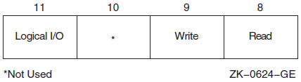
7.2.10. Device Protection
Device protection protects the allocation of nonshareable devices, such as terminals and card readers.
Protection is provided by a device protection mask similar to that of volume protection. The difference is that only the bit corresponding to read access is checked, and that bit determines whether the process can allocate or assign a channel to the device.
You establish device protection with the DCL command SET PROTECTION/DEVICE. This command sets both the protection mask and the device owner UIC.
7.2.11. System Privilege
System UIC privilege (SYSPRV) allows a process to be eligible for the volume or device protection specified for the system protection class, even if the process does not have a UIC in one of the system groups.
7.2.12. Bypass Privilege
Bypass privilege (BYPASS) allows a process to bypass volume and device protection completely.
7.3. Physical, Logical, and Virtual I/O
I/O data transfers can occur in any one of three device addressing modes:physical, logical, or virtual. Any process with device access allowed by the volume protection mask can perform logical I/O on a device that is mounted foreign; physical I/O requires privileges. Virtual I/O does not require privileges; however, intervention by an ACP to control user access might be necessary if the device is under ACP control. (ACP functions are described in the VSI OpenVMS I/O User's Reference Manual).
7.3.1. Physical I/O Operations
In physical I/O operations, data is read from and written to the actual, physically addressable units accepted by the hardware (for example, sectors on a disk or binary characters on a terminal in the PASSALL mode). This mode allows direct access to all device-level I/O operations.
The issuing process has physical I/O privilege (PHY_IO).
- The issuing process has all of the following characteristics:
The issuing process has logical I/O privilege (LOG_IO).
The device is mounted foreign.
The volume protection mask allows physical access to the device.
If neither of these conditions is met, the physical I/O operation is rejected by the SYS$QIO system service, which returns a condition value of SS$_NOPRIV (no privilege). Figure 7.2, ''Physical I/O Access Checks'' illustrates the physical I/O access checks in greater detail.
The inhibit error-logging function modifier (IO$M_INHERLOG) can be specified for all physical I/O functions. The IO$M_INHERLOG function modifier inhibits the logging of any error that occurs during the I/O operation.
7.3.2. Logical I/O Operations
n -1, where n is the number of blocks on
the device. For record-oriented or non-block-structured devices (such as terminals),
logical addressable units are not pertinent and are ignored. Logical I/O requires
that one of the following conditions be met:The issuing process has physical I/O privilege (PHY_IO).
The issuing process has logical I/O privilege (LOG_IO).
The volume is mounted foreign and the volume protection mask allows access to the device.
If none of these conditions is met, the logical I/O operation is rejected by the SYS$QIO system service, which returns a condition value of SS$_NOPRIV (no privilege). Figure 7.3, ''Logical I/O Access Checks'' illustrates the logical I/O access checks in greater detail.
7.3.3. Virtual I/O Operations
You can perform virtual I/O operations on both record-oriented (non-file-structured) and block-addressable (file-structured) devices. For record-oriented devices (such as terminals), the virtual function is the same as a logical function; the virtual addressable units of the devices are ignored.
For block-addressable devices (such as disks), data is read from and written to open files. The addressable units in the file are 512-byte blocks. They are numbered starting at 1 and are relative to a file rather than to a device. Block-addressable devices must be mounted and structured and must contain a file that was previously accessed on the I/O channel.
|
Condition Value |
Meaning |
|---|---|
|
SS$_NOPRIV |
No privilege |
|
SS$_DEVNOTMOUNT |
Device not mounted |
|
SS$_DEVFOREIGN |
Volume mounted foreign |
Figure 7.4, ''Physical, Logical, and Virtual I/O'' shows the relationship of physical, logical, and virtual I/O to the driver.
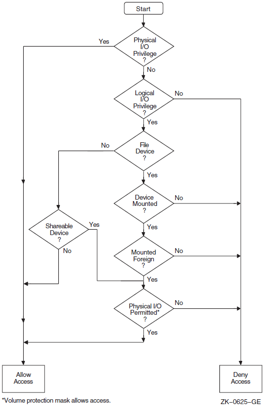
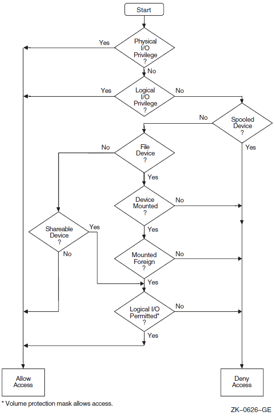
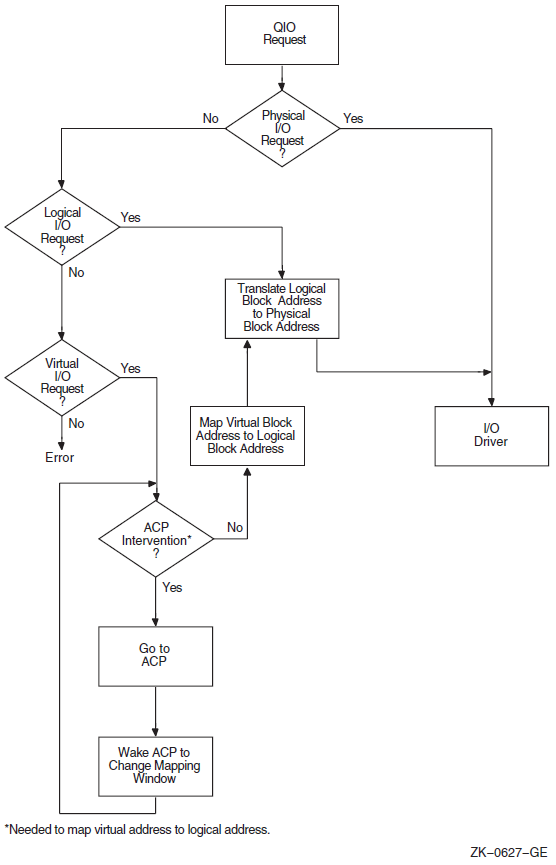
7.4. I/O Function Encoding
I/O functions fall into three groups that correspond to the three I/O device addressing modes (physical, logical, and virtual) described in Section 7.3, ''Physical, Logical, and Virtual I/O''. Depending on the device to which it is directed, an I/O function can be expressed in one, two, or all three modes.
I/O functions are described by 16-bit, symbolically expressed values that specify the particular I/O operation to be performed and any optional function modifiers. Figure 7.5, ''I/O Function Format'' shows the format of the 16-bit function value.
Symbolic names for I/O function codes are defined by the $IODEF macro.
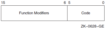
7.4.1. Function Codes
|
Physical I/O |
Logical I/O |
Virtual I/O |
|---|---|---|
|
IO$_READPBLK |
IO$_READLBLK |
IO$_READVBLK |
|
IO$_WRITEPBLK |
IO$_WRITELBLK |
IO$_WRITEVBLK |
The set mode I/O function has a symbolic value of IO$_SETMODE.
Note
You should determine the device class before performing any QIO function, because the requested function might be incompatible with some devices. For example, the SYS$INPUT device could be a terminal, a disk, or some other device. Unless this device is a terminal, an IO$_SETMODE request that enables a Ctrl/C AST is not performed.
7.4.2. Function Modifiers
The high-order 10 bits of the function value are function modifiers. These are individual bits that alter the basic operation to be performed. For example, you can specify the function modifier IO$M_NOECHO with the function IO$_READLBLK to a terminal. When used together, the two values are written in VAX MACRO as IO$_READLBLK!IO$M_NOECHO. This causes data typed at the terminal keyboard to be entered into the user buffer but not echoed to the terminal. Figure 7.6, ''Function Modifier Format'' shows the format of function modifiers.
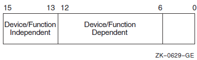
As shown in Figure 7.6, ''Function Modifier Format'', bits <15:13> are device- or function-independent bits, and bits <12:6>are device- or function-dependent bits. Device- or function-dependent bits have the same meaning, whenever possible, for different device classes. For example, the function modifier IO$M_ACCESS is used with both disk and magnetic tape devices to cause a file to be accessed during a create operation. Device- or function-dependent bits always have the same function within the same device class.
There are two device- or function-independent modifier bits: IO$M_INHRETRY and IO$M_DATACHECK (a third bit is reserved). IO$M_INHRETRY is used to inhibit all error recovery. If any error occurs and this modifier bit is specified, the operation is terminated immediately and a failure status is returned in the I/O status block (see Section 7.10, ''I/O Completion Status''). Use IO$M_DATACHECK to compare the data in memory with that on a disk or magnetic tape.
7.5. Assigning Channels
Before any input or output operation can be performed on a physical device, you must assign a channel to the device to provide a path between the process and the device. The Assign I/O Channel (SYS$ASSIGN) system service establishes this path.
When you write a call to the SYS$ASSIGN service, you must supply the name of the device, which can be a physical device name or a logical name, and the address of a word to receive the channel number. The service returns a channel number, and you use this channel number when you write an input or output request.
#include <descrip.h>
#include <lib$routines.h>
#include <ssdef.h>
#include <starlet.h>
#include <stdio.h>
#include <stsdef.h>

main() {
        unsigned int status;
        unsigned short ttchan;
        $DESCRIPTOR(ttname,"TTA2:");

        /* Assign a channel to a device */
        status = SYS$ASSIGN( &ttname,      /* devnam - device name  */
                             &ttchan,      /* chan - channel number */
                             0,            /* acmode - access mode  */
                             0,            /* mbxnam - logical name
                                              for mailbox           */
                             0 );          /* flags                 */
        if (!$VMS_STATUS_SUCCESS(status))
            LIB$SIGNAL(status);

 return SS$_NORMAL;
}
To assign a channel to the current default input or output device, use the logical name SYS$INPUT or SYS$OUTPUT.
For more details on how SYS$ASSIGN and other I/O services handle logical names, see Section 7.2.5, ''Physical I/O Privilege''.
7.5.1. Using the Share Privilege with the SYS$ASSIGN and SYS$DASSGN Services
Use of SHARE privilege should be made only with caution, as applications, application protocols, and device drivers coded to expect only exclusive access can encounter unexpected and potentially errant behavior when access to the device is unexpectedly shared via use of SHARE privilege.
If you use the SHARE privilege to override the exclusivity requested by another process's call to the system service SYS$ASSIGN, and the original process then attempts to deassign its channels via explicit calls to SYS$DASSGN or via the implicit calls to SYS$DASSGN made during image or process rundown, the OpenVMS last-channel-deassign code may not operate as expected due to the assignment of the additional I/O channels to the device. The presence of these extra channels will prevent the last-channel-deassign code from releasing the ownership of the device, potentially resulting in a device owned by the process identification (PID) of a nonexistent process.
Unless its use is explicitly supported by the application, the application protocol, and the device driver, the use of SHARE privilege is generally discouraged.
7.6. Queuing I/O Requests
All input and output operations in the operating system are initiated with the Queue I/O Request (SYS$QIO) system service. The SYS$QIO system service permits direct interaction with the system's terminal driver. SYS$QIOs permit some operations that cannot be performed with language I/O statements and RTL routines; calls to SYS$QIO reduce overhead and permit asynchronous I/O operations. However, calls to SYS$QIO are device dependent. The SYS$QIO service queues the request and returns immediately to the caller. While the operating system processes the request, the program that issued the request can continue execution.
SYS$QIO
  ([efn],chan,func[,iosb][,astadr][,astprm][,p1][,p2][,p3][,p4][,p5][,p6])
Required arguments to the SYS$QIO service include the channel number assigned to the device on which the I/O is to be performed, and a function code (expressed symbolically) that indicates the specific operation to be performed. Depending on the function code, one to six additional parameters may be required.
#include <starlet.h>

        unsigned int status, func=IO$_WRITEVBLK;
   .
   .
   .
        status = SYS$QIO(0,             /* efn - event flag       */
                        ttchan,         /* chan - channel number    */
                        func,           /* func - function modifier */
                        0,              /* iosb - I/O status block  */
                        0,              /* astadr - AST routine     */
                        0,              /* astprm - AST parameter   */
                        buffadr,        /* p1 - output buffer       */
                        buflen);        /* p2 - length of message   */
Function codes are defined for all supported device types, and most of the codes are device dependent; that is, they perform functions specific to a particular device. The $IODEF macro defines symbolic names for these function codes. For information about how to obtain a listing of these symbolic names, see Appendix A, "Generic Macros for Calling System Services". For details about all function codes and an explanation of the parameters required by each, see the VSI OpenVMS I/O User's Reference Manual.
To read from or write to a terminal with the SYS$QIO or SYS$QIOW system service, you must first associate the terminal name with an I/O channel by calling the SYS$ASSIGN system service, then use the assigned channel in the SYS$QIO or SYS$QIOW system service. To read from SYS$INPUT or write to SYS$OUTPUT, specify the appropriate logical name as the terminal name in the SYS$ASSIGN system service. In general, use SYS$QIO for asynchronous operations, and use SYS$QIOW for all other operations.
7.7. Synchronizing Service Completion
Test whether the operation was queued successfully.
Test whether the operation itself completed successfully.
Specify the number of an event flag to be set when the operation completes.
Specify the address of an AST routine to be executed when the operation completes.
Specify the address of an I/O status block in which the system can place the return status when the operation completes.
I/O status blocks are explained in Section 7.10, ''I/O Completion Status''.
#include <lib$routines.h> #include <starlet.h> unsigned int status, efn=0, efn1=1, efn=2; . . . status = SYS$QIO(efn1,...); /* Issue 1st I/O request */ if (!$VMS_STATUS_SUCCESS(status)) LIB$SIGNAL( status ); /* Queued successfully? */
| When you specify an event flag number as an argument, SYS$QIO clears the event flag when it queues the I/O request. When the I/O completes, the flag is set. |
| In this example, the program issues two Queue I/O requests. A different event flag is specified for each request. |
| The Wait for Logical AND of Event Flags
(SYS$WFLAND) system service places the process
in a wait state until both I/O operations are complete. The
|
| Note that the SYS$WFLAND system service (and the other wait system services) wait for the event flag to be set; they do not wait for the I/O operation to complete. If some other event were to set the required event flags, the wait for event flag would complete too soon. You must coordinate the use of event flags carefully. (See Section 7.8, ''Recommended Method for Testing Asynchronous Completion'' for a discussion of the recommended method for testing I/O completion). |
#include <lib$routines.h>
#include <starlet.h>
#include <stsdef.h>
        unsigned int status, astprm=1;
   .
   .
   .
        status = SYS$QIO(...&ttast,   /* I/O request with AST */
                        astprm...);
        if (!$VMS_STATUS_SUCCESS( status ))   /* Queued successfully? */
                LIB$SIGNAL( status );
   .
   .
   .
}

void ttast ( int astprm ) {                   /* AST service routine */

/* Handle I/O completion */
   .
   .
   .

        return;
}                              /* End of AST routine */
| When you specify the The SYS$QIO system service call specifies the address of the AST routine, TTAST, and a parameter to pass as an argument to the AST service routine. When$QIO returns control, the process continues execution. |
| When the I/O completes, the AST routine TTAST is called, and it responds to the I/O completion. By examining the AST parameter, TTAST can determine the origin of the I/O request. When this routine is finished executing, control returns to the process at
the point at which it was interrupted. If you specify the
|
#include <lib$routines.h> #include <stdio.h> #include <ssdef.h> #include <starlet.h> #include <stsdef.h> . . . /* I/O status block */ struct { unsigned short iostat, iolen; unsigned int dev_info; }ttiosb;
| An I/O status block is a quadword structure that the system uses to post
the status of an I/O operation. You must define the quadword area in your
program. TTIOSB defines the I/O status block for this I/O operation. The
|
| Instead of polling the low-order word of the I/O status block for the completion status, the program uses the preferred method of using an event flag and calling SYS$SYNCH to determine I/O completion. |
| The process polls the I/O status block. If the low-order word still contains zero, the I/O operation has not yet completed. In this example, the program loops until the request is complete. |
7.8. Recommended Method for Testing Asynchronous Completion
VSI recommends that you use the Synchronize (SYS$SYNCH) system service to wait for completion of an asynchronous event. The SYS$SYNCH service correctly waits for the actual completion of an asynchronous event, even if some other event sets the event flag.
To use the SYS$SYNCH service to wait for the completion of an asynchronous event, you must specify both an event flag number and the address of an I/O status block (IOSB) in your call to the asynchronous system service. The asynchronous service queues the request and returns control to your program. When the asynchronous service completes, it sets the event flag and places the final status of the request in the IOSB.
In your call to SYS$SYNCH, you must specify the same
efn and I/O status block that you specified in your call to
the asynchronous service. The SYS$SYNCH service waits for the
event flag to be set by means of the SYS$WAITFR system service.
When the specified event flag is set, SYS$SYNCH checks the
specified I/O status block. If the I/O status block is nonzero, the system service has
completed and SYS$SYNCH returns control to your program. If the
I/O status block is zero, SYS$SYNCH clears the event flag by
means of the SYS$CLREF service and calls the
$WAITFR service to wait for the event flag to be
set.
The SYS$SYNCH service sets the event flag before returning control to your program. This ensures that the call to SYS$SYNCH does not interfere with testing for completion of another asynchronous event that completes at approximately the same time and uses the same event flag to signal completion.
   .
   .
   .
#include <lib$routines.h>
#include <starlet.h>
        unsigned int status, event_flag = 1;
        struct {
                        short int iostat, iolen;
                        unsigned int dev_info;
}ttiosb;
   .
   .
   .
/* Request I/O */
        status = SYS$QIO (event_flag, ..., &ttiosb ...);
        if (!$VMS_STATUS_SUCCESS(status))
                LIB$SIGNAL( status );
   .
   .
   .
/* Wait until I/O completes */
        status = SYS$SYNCH (event_flag, &ttiosb );
        if (!$VMS_STATUS_SUCCESS(status))
                LIB$SIGNAL( status );
   .
   .
   .
Note
The SYS$QIOW service provides a combination of SYS$QIO and SYS$SYNCH.
7.9. Synchronous and Asynchronous Forms of Input/Output Services
You can execute some input/output services either synchronously or asynchronously. A "W" at the end of a system service name indicates the synchronous version of the system service.
The synchronous version of a system service combines the functions of the asynchronous version of the service and the Synchronize (SYS$SYNCH) system service. The synchronous version acts exactly as if you had used the asynchronous version of the system service followed immediately by a call to SYS$SYNCH; it queues the I/O request, and then places the program in a wait state until the I/O request completes. The synchronous version takes the same arguments as the asynchronous version.
|
Asynchronous Name |
Synchronous Name |
Description |
|---|---|---|
|
$BRKTHRU |
$BRKTHRUW |
Breakthrough |
|
$GETDVI |
$GETDVIW |
Get Device/Volume Information |
|
$GETJPI |
$GETJPIW |
Get Job/Process Information |
|
$GETLKI |
$GETLKIW |
Get Lock Information |
|
$GETQUI |
$GETQUIW |
Get Queue Information |
|
$GETSYI |
$GETSYIW |
Get Systemwide Information |
|
$QIO |
$QIOW |
Queue I/O Request |
|
$SNDJBC |
$SNDJBCW |
Send to Job Controller |
|
$UPDSEC |
$UPDSECW |
Update Section File on Disk |
7.9.1. Reading Operations with SYS$QIOW
The SYS$QIO and SYS$QIOW system services move one record of data from a terminal to a variable. For synchronous I/O, use SYS$QIOW. Complete information about the SYS$QIO and SYS$QIOW system services is presented in the VSI OpenVMS System Services Reference Manual.
The SYS$QIO and SYS$QIOW system
services place the data read in the variable specified in the
1 argument. The second word of the status block contains
the offset from the beginning of the buffer to the terminator—hence, it equals
the size of the data read. Always reference the data as a substring, using the
offset to the terminator as the position of the last character (that is, the size of
the substring). If you reference the entire buffer, your data will include the
terminator for the operation (for example, the CR character) and any excess
characters from a previous operation using the buffer. (The only exception to the
substring guideline is if you deliberately overflow the buffer to terminate the I/O
operation).
   .
   .
   .
INTEGER STATUS
! QIOW structures
INTEGER*2 INPUT_CHAN             ! I/O channel
INTEGER CODE,                    ! Type of I/O operation
2       INPUT_BUFF_SIZE,         ! Size of input buffer
2       PROMPT_SIZE,             ! Size of prompt
2       INPUT_SIZE               ! Size of input line as read
PARAMETER (PROMPT_SIZE = 13,
2          INPUT_BUFF_SIZE = 132)
CHARACTER*132 INPUT
CHARACTER*(*) PROMPT
PARAMETER (PROMPT = 'Input value: ')
! Define symbols used in I/O operations
INCLUDE '($IODEF)'
! Status block for QIOW
STRUCTURE /IOSTAT_BLOCK/
  INTEGER*2 IOSTAT,              ! Return status
2           TERM_OFFSET,         ! Location of line terminator
2           TERMINATOR,          ! Value of terminator
2           TERM_SIZE            ! Size of terminator
END STRUCTURE
RECORD /IOSTAT_BLOCK/ IOSB
! Subprograms
INTEGER*4 SYS$ASSIGN,
2         SYS$QIOW
   .
   .
   .
! Assign an I/O channel to SYS$INPUT
STATUS = SYS$ASSIGN ('SYS$INPUT',
2                    INPUT_CHAN,,)
IF (.NOT. STATUS) CALL LIB$SIGNAL (%VAL (STATUS))
! Read with prompt
CODE = IO$_READPROMPT
STATUS = SYS$QIOW (,
2                  %VAL (INPUT_CHAN),
2                  %VAL (CODE),
2                  IOSB,
2                  ,,
2                  %REF (INPUT),
2                  %VAL (INPUT_BUFF_SIZE),
2                  ,,
2                  %REF (PROMPT),
2                  %VAL (PROMPT_SIZE))
! Check QIOW status
IF (.NOT. STATUS) CALL LIB$SIGNAL (%VAL (STATUS))
! Check status of I/O operation
IF (.NOT. IOSB.IOSTAT) CALL LIB$SIGNAL (%VAL (IOSB.IOSTAT))
! Set size of input string
INPUT_SIZE = IOSB.TERM_OFFSET
   .
   .
   .
7.9.2. Reading Operations with SYS$QIO
   .
   .
   .
INTEGER STATUS
! QIO structures
INTEGER*2 INPUT_CHAN     ! I/O channel
INTEGER CODE,            ! Type of I/O operation
2       INPUT_BUFF_SIZE, ! Size of input buffer
2       PROMPT_SIZE,     ! Size of prompt
2       INPUT_SIZE       ! Size of input line as read
PARAMETER (INPUT_BUFF_SIZE = 132,
2          PROMPT = 13)
CHARACTER*132 INPUT
CHARACTER*(*) PROMPT
PARAMETER (PROMPT = 'Input value: ')
INCLUDE '($IODEF)'        ! Symbols used in I/O operations
! Status block for QIO
STRUCTURE /IOSTAT_BLOCK/
  INTEGER*2 IOSTAT,       ! Return status
2           TERM_OFFSET,  ! Location of line terminator
2           TERMINATOR,   ! Value of terminator
2           TERM_SIZE     ! Size of terminator
END STRUCTURE
RECORD /IOSTAT_BLOCK/ IOSB
! Event flag for I/O
INTEGER INPUT_EF
! Subprograms
INTEGER*4 SYS$ASSIGN,
2         SYS$QIO,
2         SYS$SYNCH,
2         LIB$GET_EF
   .
   .
   .
! Assign an I/O channel to SYS$INPUT
STATUS = SYS$ASSIGN ('SYS$INPUT',
2                    INPUT_CHAN,,)
IF (.NOT. STATUS) CALL LIB$SIGNAL (%VAL (STATUS))
! Get an event flag
STATUS = LIB$GET_EF (INPUT_EF)
IF (.NOT. STATUS) CALL LIB$SIGNAL (%VAL (STATUS))
! Read with prompt
CODE = IO$_READPROMPT
STATUS = SYS$QIO (%VAL (INPUT_EF),
2                 %VAL (INPUT_CHAN),
2                 %VAL (CODE),
2                 IOSB,
2                 ,,
2                 %REF (INPUT),
2                 %VAL (INPUT_BUFF_SIZE),
2                 ,,
2                 %REF (PROMPT),
2                 %VAL (PROMPT_SIZE))
! Check status of QIO
IF (.NOT. STATUS) CALL LIB$SIGNAL (%VAL (STATUS))
   .
   .
   .
STATUS = SYS$SYNCH (%VAL (INPUT_EF),
2                   IOSB)
! Check status of SYNCH
IF (.NOT. STATUS) CALL LIB$SIGNAL (%VAL (STATUS))
! Check status of I/O operation
IF (.NOT. IOSB.IOSTAT) CALL LIB$SIGNAL (%VAL (IOSB.IOSTAT))
! Set size of input string
INPUT_SIZE = IOSB.TERM_OFFSET
   .
   .
   .
Be sure to check the status of the I/O operation as returned in the I/O status block. In an asynchronous operation, you can check this status only after the I/O operation is complete (that is, after the call to SYS$SYNCH).
7.9.3. Write Operations with SYS$QIOW
The SYS$QIO and SYS$QIOW system services move one record of data from a character value to the terminal. Do not use these system services, as described here, for output to a file or nonterminal device.
For synchronous I/O, use SYS$QIOW and omit the first argument (the event flag number). For complete information about SYS$QIO and SYS$QIOW, refer to the VSI OpenVMS System Services Reference Manual.
INTEGER STATUS,
2       ANSWER_SIZE
CHARACTER*31 ANSWER
INTEGER*2 OUT_CHAN
! Status block for QIO
STRUCTURE /IOSTAT_BLOCK/
  INTEGER*2 IOSTAT,
2           BYTE_COUNT,
2           LINES_OUTPUT
  BYTE      COLUMN,
2           LINE
END STRUCTURE
RECORD /IOSTAT_BLOCK/ IOSB
! Routines
INTEGER SYS$ASSIGN,
2       SYS$QIOW
! IO$ symbol definitions
INCLUDE '($IODEF)'
   .
   .
   .
STATUS = SYS$ASSIGN ('SYS$OUTPUT',
2                    OUT_CHAN,,)
IF (.NOT. STATUS) CALL LIB$SIGNAL (%VAL (STATUS))
STATUS = SYS$QIOW (,
2                  %VAL (OUT_CHAN),
2                  %VAL (IO$_WRITEVBLK),
2                  IOSB,
2                  ,
2                  ,
2                  %REF ('Answer: '//ANSWER(1:ANSWER_SIZE)),
2                  %VAL (8+ANSWER_SIZE),
2                  ,
2                  %VAL (32),,) ! Single spacing
IF (.NOT. STATUS) CALL LIB$SIGNAL (%VAL (STATUS))
IF (.NOT. IOSB.IOSTAT) CALL LIB$SIGNAL (%VAL (IOSB.IOSTAT))
END
7.10. I/O Completion Status
When an I/O operation completes, the system posts the completion status in the I/O status block, if one is specified. The completion status indicates whether the operation completed successfully, the number of bytes that were transferred, and additional device-dependent return information.
Figure 7.7, ''I/O Status Block'' illustrates the format for the SYS$QIO system service of the information written in the IOSB.
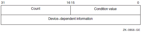
The first word contains a system status code indicating the success or failure of the operation. The status codes used are the same as for all returns from system services; for example, SS$_NORMAL indicates successful completion.
The second word contains the number of bytes actually transferred in the I/O operation. Note that for some devices this word contains only the low-order word of the count. For information about specific devices, see the VSI OpenVMS I/O User's Reference Manual.
The second longword contains device-dependent return information.
System services other than SYS$QIO use the quadword I/O status block, but the format is different. See the description of each system service in the VSI OpenVMS System Services Reference Manual for the format of the information written in the IOSB for that service.
To ensure successful I/O completion and the integrity of data transfers, you should check the IOSB following I/O requests, particularly for device-dependent I/O functions. For complete details about how to use the I/O status block, see the VSI OpenVMS I/O User's Reference Manual.
7.11. Deassigning I/O Channels
$DASSGN_S CHAN=TTCHAN
This service call releases the terminal channel assignment acquired in the SYS$ASSIGN example shown in Section 7.5, ''Assigning Channels''. The system automatically deassigns channels for a process when the image that assigned the channel exits.
7.12. Using Complete Terminal I/O
#include <descrip.h> #include <iodef.h> #include <lib$routines.h> #include <ssdef.h> #include <starlet.h> #include <stdio.h> #include <string.h> #define BUFSIZ 80 /* I/O status block */ struct {/* Deassign the channel */ status = SYS$DASSGN( ttchan ); /* chan - channel */
if (!$VMS_STATUS_SUCCESS( status )) LIB$SIGNAL( status ); }
| The IOSB for the I/O operations is structured so that the program can easily check for the completion status (in the first word) and the length of the input string returned (in the second word). |
| The string will be read into the buffer BUFFER; the longword OUTLEN will contain the length of the string for the output operation. |
| The TTNAME label is a character string descriptor for the logical device SYS$INPUT, and TTCHAN is a word to receive the channel number assigned to it. |
| The $ASSIGN service assigns a channel and writes the channel number at TTCHAN. |
| If the $ASSIGN service completes successfully, the $QIOW macro reads a line from the terminal, and requests that the completion status be posted in the I/O status block defined at TTIOSB. |
| The process waits until the I/O is complete, then checks the first word in the I/O status block for a successful return. If unsuccessful, the program takes an error path. |
| The length of the string read is moved into the longword at OUTLEN, because the $QIOW macro requires a longword argument. However, the length field of the I/O status block is only 1 word long. The $QIOW macro writes the line just read to the terminal. |
| The program performs error checks. First, it ensures that the $OUTPUT macro successfully queued the I/O request; then, when the request is completed, it ensures that the I/O was successful. |
| When all I/O operations on the channel are finished, the channel is deassigned. |
7.13. Canceling I/O Requests
If a process must cancel I/O requests that have been queued but not yet completed, it can issue the Cancel I/O On Channel (SYS$CANCEL) system service. All pending I/O requests issued by the process on that channel are canceled; you cannot specify a particular I/O request.
The SYS$CANCEL system service performs an asynchronous cancel operation. This means that the application must wait for each I/O operation issued to the driver to complete before checking the status for that operation.
        unsigned int status, efn1=3, efn2=4;
   .
   .
   .
        status = SYS$QIO(efn1, ttchan, &iosb1, ...);
        status = SYS$QIO(efn2, ttchan, &iosb2, ...);
   .
   .
   .
        status = SYS$CANCEL(ttchan);
        status = SYS$SYNCH(efn1, &iosb1);
        status = SYS$SYNCH(efn2, &iosb2);
In this example, the SYS$CANCEL system service initiates the cancellation of all pending I/O requests to the channel whose number is located at TTCHAN.
The SYS$CANCEL system service returns after initiating the cancellation of the I/O requests. If the call to SYS$QIO specified either an event flag, AST service routine, or I/O status block, the system sets either the flag, delivers the AST, or posts the I/O status block as appropriate when the cancellation is completed.
7.14. Logical Names and Physical Device Names
When you specify a device name as input to an I/O system service, it can be a physical device name or a logical name. If the device name contains a colon (:), the colon and the characters after it are ignored. When an underscore character (_) precedes a device name string, it indicates that the string is a physical device name string, for example, _TTB3:.
|
System Service |
Definition |
|---|---|
|
SYS$ALLOC |
Allocate Device |
|
SYS$ASSIGN |
Assign I/O Channel |
|
SYS$BRDCST |
Broadcast |
|
SYS$DALLOC |
Deallocate Device |
|
SYS$DISMOU |
Dismount Volume |
|
SYS$GETDEV |
Get I/O Device Information |
|
SYS$GETDVI |
Get Device/Volume Information |
|
SYS$MOUNT |
Mount Volume |
In each translation, the logical name tables defined by the logical name LNM$FILE_DEV are searched in order. These tables, listed in search order, are normally LNM$PROCESS, LNM$JOB, LNM$GROUP, and LNM$SYSTEM. If a physical device name is located, the I/O request is performed for that device.
If the services do not locate an entry for the logical name, the I/O service treats the name specified as a physical device name. When you specify the name of an actual physical device in a call to one of these services, include the underscore character to bypass the logical name translation.
When the SYS$ALLOC system service returns the device name of the physical device that has been allocated, the device name string returned is prefixed with an underscore character. When this name is used for the subsequent SYS$ASSIGN system service, the SYS$ASSIGN service does not attempt to translate the device name.
If you use logical names in I/O service calls, you must be sure to establish a valid device name equivalence before program execution. You can do this either by issuing a DEFINE command from the command stream, or by having the program establish the equivalence name before the I/O service call with the Create Logical Name (SYS$CRELNM) system service.
For details about how to create and use logical names, see Chapter 18, "Logical Name and Logical Name Tables".
7.15. Device Name Defaults
If, after logical name translation, a device name string in an I/O system service call does not fully specify the device name (that is, device, controller, and unit), the service either provides default values for nonspecified fields, or provides values based on device availability.
The SYS$ASSIGN and SYS$DALLOC system services apply default values, as shown in Table 7.4, ''Default Device Names for I/O Services''.
The SYS$ALLOC system service treats the device name as a generic device name and attempts to find a device that satisfies the components of the device name specified, as shown in Table 7.4, ''Default Device Names for I/O Services''.
|
Device |
Device Name? |
Generic Device |
|---|---|---|
|
Key
| ||
|
dd: |
ddA0: (unit 0 on controller A) |
ddxy: (any available device of the specified type) |
|
ddc: |
ddc0: (unit 0 on controller specified) |
ddcy: (any available unit on the specified controller) |
|
ddu: |
ddA u: (unit specified on controller A) |
ddxu: (device of specified type and unit on any available controller) |
|
ddcu: |
ddcu: (unit and controller specified) |
ddcu: (unit and controller specified) |
7.16. Obtaining Information About Physical Devices
The Get Device/Volume Information (SYS$GETDVI) system service returns information about devices. The information returned is specified by an item list created before the call to SYS$GETDVI.
When you call the SYS$GETDVI system service, you must provide the address of an item list that specifies the information to be returned. The format of the item list is described in the description of SYS$GETDVI in the VSI OpenVMS System Services Reference Manual. The VSI OpenVMS I/O User's Reference Manual contains details on the device-specific information these services return.
In cases where a generic (that is, nonspecific) device name is used in an I/O service, a program may need to find out what device has been used. To do this, the program should provide SYS$GETDVI with the number of the channel to the device and request the name of the device with the DVI$_DEVNAM item identifier.
A read from NL returns an end-of-file error (SS$_ENDOFFILE).
A write to NL immediately returns a success message (SS$_NORMAL).
The null device functions as a virtual device to which you can direct output but from which the data does not return.
7.16.1. Checking the Terminal Device
RECORD /ITMLST/ DVI_LIST
LOGICAL*4 STATUS
! GETDVI buffers
INTEGER CLASS,             ! Response buffer
2       CLASS_LEN          ! Response length
! GETDVI symbols
INCLUDE '($DCDEF)'
INCLUDE '($SSDEF)'
INCLUDE '($DVIDEF)'
! Define subprograms
INTEGER SYS$GETDVIW
! Find out the device class of SYS$INPUT
DVI_LIST.BUFLEN = 4
DVI_LIST.CODE = DVI$_DEVCLASS
DVI_LIST.BUFADR = %LOC (CLASS)
DVI_LIST.RETLENADR = %LOC (CLASS_LEN)
STATUS = SYS$GETDVIW (,,'SYS$INPUT',
2                     DVI_LIST,,,,,)
IF ((.NOT. STATUS) .AND. (STATUS .NE. SS$_IVDEVNAM)) THEN
  CALL LIB$SIGNAL (%VAL (STATUS))
END IF
! Make sure device is a terminal
IF ((STATUS .NE. SS$_IVDEVNAM) .AND. (CLASS .EQ. DC$_TERM)) THEN
   .
   .
   .
ELSE
  TYPE *, 'Input device not a terminal'
END IF
7.16.2. Terminal Characteristics
P1 argument.
To change a characteristic:Issue a call to SYS$QIO or SYS$QIOW system service with the IO$_SENSEMODE function.
Set or clear the appropriate bit in the structure returned to the
P1argument.Issue a call to SYS$QIO or SYS$QIOW system service with the IO$_SETMODE function passing, as the
P1argument, to modify the structure you obtained from the sense mode operation.
   .
   .
   .
INTEGER*4 STATUS
! I/O channel
INTEGER*2 INPUT_CHAN
! I/O status block
STRUCTURE /IOSTAT_BLOCK/
  INTEGER*2 IOSTAT
  BYTE      TRANSMIT,
2           RECEIVE,
2           CRFILL,
2           LFFILL,
2           PARITY,
2           ZERO
END STRUCTURE
RECORD /IOSTAT_BLOCK/ IOSB
! Characteristics buffer
! Note: basic characteristics are first three
!       bytes of second longword -- length is
!       last byte
STRUCTURE /CHARACTERISTICS/
  BYTE      CLASS,
2           TYPE
  INTEGER*2 WIDTH
  UNION
   MAP
    INTEGER*4 BASIC
   END MAP
   MAP
    BYTE LENGTH(4)
   END MAP
  END UNION
  INTEGER*4 EXTENDED
END STRUCTURE
RECORD /CHARACTERISTICS/ CHARBUF
! Define symbols used for I/O and terminal operations
INCLUDE '($IODEF)'
INCLUDE '($TTDEF)'
! Subroutines
INTEGER*4 SYS$ASSIGN,
2         SYS$QIOW
! Assign channel to terminal
STATUS = SYS$ASSIGN ('SYS$INPUT',
2                    INPUT_CHAN,,)
IF (.NOT. STATUS) CALL LIB$SIGNAL (%VAL (STATUS))
! Get current characteristics
STATUS = SYS$QIOW (,
2                  %VAL (INPUT_CHAN),
2                  %VAL (IO$_SENSEMODE),
2                  IOSB,,,
2                  CHARBUF,          ! Buffer
2                  %VAL (12),,,,)    ! Buffer size
IF (.NOT. STATUS) CALL LIB$SIGNAL (%VAL (STATUS))
IF (.NOT. IOSB.IOSTAT) CALL LIB$SIGNAL (%VAL (IOSB.IOSTAT))
! Turn off hostsync
CHARBUF.BASIC = IBCLR (CHARBUF.BASIC, TT$V_HOSTSYNC)
! Set new characteristics
STATUS = SYS$QIOW (,
2                  %VAL (INPUT_CHAN),
2                  %VAL (IO$_SETMODE),
2                  IOSB,,,
2                  CHARBUF,
2                  %VAL (12),,,,)
IF (.NOT. STATUS) CALL LIB$SIGNAL (%VAL (STATUS))
IF (.NOT. IOSB.IOSTAT) CALL LIB$SIGNAL (%VAL (IOSB.IOSTAT))

END
If you modify terminal characteristics with set mode QIO operations, you should save the characteristics buffer that you obtain on the first sense mode operation, and restore those characteristics with a set mode operation before exiting. (Resetting is not necessary if you just use modifiers on each read operation). To ensure that the restoration is performed if the program aborts (for example, if the user presses Ctrl/Y), you should restore the user's environment in an exit handler. See VSI OpenVMS Programming Concepts Manual, Volume I for a description of exit handlers.
7.16.3. Record Terminators
A QIO read operation ends when the user enters a terminator or when the input
buffer fills, whichever occurs first. The standard set of terminators applies unless
you specify the 4 argument in the read QIO operation. You can
examine the terminator that ended the read operation by examining the input buffer
starting at the terminator offset (second word of the I/O status block). The length,
in bytes, of the terminator is specified by the high-order word of the I/O status
block. The third word of the I/O status block contains the value of the first
character of the terminator.
Examining the terminator enables you to read escape sequences from the terminal, provided that you modify the QIO read operation with the IO$M_ESCAPE modifier (or the ESCAPE terminal characteristic is set). The first character of the terminator will be the ESC character (an ASCII value of 27). The remaining characters will contain the value of the escape sequence.
7.16.4. File Terminators
You must examine the terminator to detect end-of-file (Ctrl/Z) on the terminal. No error condition is generated at the QIO level. If the user presses Ctrl/Z, the terminator will be the SUB character (an ASCII value of 26).
7.17. Device Allocation
Many I/O devices are shareable; that is, more than one process at a time can access the device. By calling the Assign I/O Channel (SYS$ASSIGN) system service, a process is given a channel to the device for I/O operations.
In some cases, a process may need exclusive use of a device so that data is not affected by other processes. To reserve a device for exclusive use, you must allocate it.
Device allocation is normally accomplished with the DCL command ALLOCATE. A process can also allocate a device by calling the Allocate Device (SYS$ALLOC) system service. When a device has been allocated by a process, only the process that allocated the device and any subprocesses it creates can assign channels to the device.
A physical device name, for example, the tape drive MTB3:
A logical name, for example, TAPE
A generic device name, for example, MT:
If you specify a physical device name, SYS$ALLOC attempts to allocate the specified device.
If you specify a logical name, SYS$ALLOC translates the logical name and attempts to allocate the physical device name equated to the logical name.
If you specify a generic device name (that is, if you specify a device type but do not specify a controller or unit number, or both), SYS$ALLOC attempts to allocate any device available of the specified type. For more information about the allocation of devices by generic names, see Section 7.15, ''Device Name Defaults''.
When you specify generic device names, you must provide fields for the SYS$ALLOC system service to return the name and the length of the physical device that is actually allocated so that you can provide this name as input to the SYS$ASSIGN system service.
#include <descrip.h>
#include <lib$routines.h>
#include <ssdef.h>
#include <starlet.h>
#include <stdio.h>

main() {
        unsigned int status;
        char devstr[64];
        unsigned short phylen, tapechan;

        $DESCRIPTOR(logdev,"TAPE");     /* Descriptor for logical name */
        $DESCRIPTOR(devdesc,devstr);    /* Descriptor for physical name */

/* Allocate a device */
        status = SYS$ALLOC( &logdev,    /* devnam - device name */
                            &phylen,    /* phylen - length device name
                                           string */
                            &devdesc,   /* phybuf - buffer for devnam
                                           string */
                            0, 0);
        if (!$VMS_STATUS_SUCCESS( status ))
                LIB$SIGNAL( status );

/* Assign a channel to the device */
        status = SYS$ASSIGN( &devdesc,   /* devnam - device name */
                             &tapechan,  /* chan - channel number */
                             0, 0, 0);
        if (!$VMS_STATUS_SUCCESS( status ))
                LIB$SIGNAL( status );

/* Deassign the channel */
        status = SYS$DASSGN( tapechan );  /* chan - channel number */
        if (!$VMS_STATUS_SUCCESS( status ))
                LIB$SIGNAL( status );

/* Deallocate the device */
        status = SYS$DALLOC( &devdesc,    /* devnam - device name */
                             0 );         /* acmode - access mode */
        if (!$VMS_STATUS_SUCCESS( status ))
                LIB$SIGNAL( status );

}
| The SYS$ALLOC system service call requests allocation of a device corresponding to the logical name TAPE, defined by the character string descriptor LOGDEV. The argument DEVDESC refers to the buffer provided to receive the physical device name of the device that is allocated and the length of the name string. The SYS$ALLOC service translates the logical name TAPE and returns the equivalence name string of the device actually allocated into the buffer at DEVDESC. It writes the length of the string in the first word of DEVDESC. |
| The SYS$ASSIGN command uses the character string returned by the SYS$ALLOC system service as the input device name argument, and requests that the channel number be written into TAPECHAN. |
| When I/O operations are completed, the SYS$DASSGN system service deassigns the channel, and the SYS$DALLOC system service deallocates the device. The channel must be deassigned before the device can be deallocated. |
7.17.1. Implicit Allocation
Devices that cannot be shared by more than one process (for example, terminals and line printers) do not have to be explicitly allocated. Because they are nonshareable, they are implicitly allocated by the SYS$ASSIGN system service when SYS$ASSIGN is called to assign a channel to the device.
7.17.2. Deallocation
When the program has finished using an allocated device, it should release the device with the Deallocate Device (SYS$DALLOC) system service to make it available for other processes.
At image exit, the system automatically deallocates devices allocated by the image.
7.18. Mounting, Dismounting, and Initializing Volumes
This section introduces you to using system services to mount, dismount, and initialize disk and tape volumes.
7.18.1. Mounting a Volume
Mounting a volume establishes a link between a volume, a device, and a process. A volume, or volume set, must be mounted before I/O operations can be performed on the volume. You interactively mount or dismount a volume from the DCL command stream with the MOUNT or DISMOUNT command. A process can also mount or dismount a volume or volume set programmatically using the Mount Volume (SYS$MOUNT) or the Dismount Volume (SYS$DISMOU) system service, respectively.
Place the volume on the device and start the device (by pressing the START or LOAD button).
Mount the volume with the SYS$MOUNT system service.
7.18.1.1. Calling the SYS$MOUNT System Service
The Mount Volume (SYS$MOUNT) system service allows a process to mount a single volume or a volume set. When you call the SYS$MOUNT system service, you must specify a device name.
The SYS$MOUNT system service has a single argument, which is the address of a list of item descriptors. The list is terminated by a longword of binary zeros. Figure 7.8, ''SYS$MOUNT Item Descriptor'' shows the format of an item descriptor.
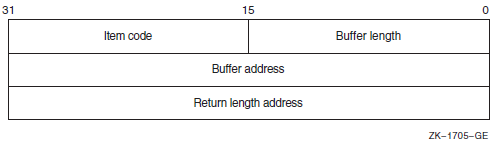
Most item descriptors do not have to be in any order. To mount volume sets, you must specify one item descriptor per device and one item descriptor per volume; you must specify the descriptors for the volumes in the same order as the descriptors for the devices on which the volumes are loaded.
For item descriptors other than device and volume names, if you specify the same item descriptor more than once, the last occurrence of the descriptor is used.
$ MOUNT/SYSTEM/NOQUOTA DRA4:,DRA5: USER01,USER02 USERD$#include <descrip.h> #include <lib$routines.h> #include <mntdef.h> #include <starlet.h> #include <stdio.h> . . . struct { unsigned short buflen, item_code; void *bufaddr; int *retlenaddr; }itm; struct itm itm[7]; main() { . . . unsigned int status, flags; $DESCRIPTOR(dev1,"DRA4:"); $DESCRIPTOR(vol1,"USER01"); $DESCRIPTOR(dev2,"DRA5:"); $DESCRIPTOR(vol2,"USER02"); $DESCRIPTOR(log,"USERD$:"); flags = MNT$M_SYSTEM | MNT$M_NODISKQ; i = 0; itm[i].buflen = sizeof( flags ); itm[i].item_code = MNT$_FLAGS; itm[i].bufaddr = flags; itm[i++].retlenaddr = NULL; itm[i].buflen = dev1.dsc$w_length; itm[i].item_code = MNT$_DEVNAM; itm[i].bufaddr = dev1.dsc$a_pointer; itm[i++].retlenaddr = NULL; itm[i].buflen = vol1.dsc$w_length; itm[i].item_code = MNT$_VOLNAM; itm[i].bufaddr = vol1.dsc$a_pointer; itm[i++].retlenaddr = NULL; itm[i].buflen = dev2.dsc$w_length; itm[i].item_code = MNT$_DEVNAM; itm[i].bufaddr = dev2.dsc$a_pointer; itm[i++].retlenaddr = NULL; itm[i].buflen = vol2.dsc$w_length; itm[i].item_code = MNT$_VOLNAM; itm[i].bufaddr = vol2.dsc$a_pointer; itm[i++].retlenaddr = NULL; itm[i].buflen = log.dsc$w_length; itm[i].item_code = MNT$_LOGNAM; itm[i].bufaddr = log.dsc$a_pointer; itm[i++].retlenaddr = NULL; itm[i].buflen = 0; itm[i].item_code = 0; itm[i].bufaddr = NULL; itm[i++].retlenaddr = NULL; . . . status = SYS$MOUNT ( itm ); if (!$VMS_STATUS_SUCCESS(status)) LIB$SIGNAL( status ); . . . }
7.18.1.2. Calling the SYS$DISMOU System Service
The SYS$DISMOU system service allows a process to dismount a volume or volume set. When you call SYS$DISMOU, you must specify a device name. If the volume mounted on the device is part of a fully mounted volume set, and you do not specify flags, the whole volume set is dismounted.
    $DESCRIPTOR(dev1_desc,"DRA4:");
   .
   .
   .
        status = SYS$DISMOU(&dev1_desc); /* devnam - device */
   .
   .
   .
7.18.2. Initializing Volumes
Initializing a volume writes a label on the volume, sets protection and ownership for the volume, formats the volume (depending on the device type), and overwrites data already on the volume.
You interactively initialize a volume from the DCL command stream using the INITIALIZE command. A process can programmatically initialize a volume using the Initialize Volume (SYS$INIT_VOL) system service.
7.18.2.1. Calling the Initialize Volume System Service
You must specify a device name and a new volume name when you call the
SYS$INIT_VOL system service. You can also use the
itmlst argument of $INIT_VOL
to specify options for the initialization. For example, you can specify that
data compaction should be performed by specifying the
INIT$_COMPACTION item code. See the VSI OpenVMS System Services Reference Manual
for more information on initialization options.
Before initializing the volume with SYS$INIT_VOL, be sure you have placed the volume on the device and started the device (by pressing the START or LOAD button).
The default format for files on disk volumes is called Files-11 On-Disk Structure Level 2. Files-11 On-Disk Structure Level 1 format, available on VAX systems, is used by other HP operating systems, including RSX-11M, RSX-11M-PLUS, RSX-11D, and IAS, but is not supported on Alpha systems. For more information, see the VSI OpenVMS System Manager's Manual.
Here are two examples of calling SYS$INIT_VOL programmatically: one from a C program and one from a BASIC program.
#include <descrip.h>
#include <initdef.h>
#include <lib$routines.h>
#include <starlet.h>
#include <stsdef.h>

struct item_descrip_3
{
    unsigned short buffer_size;
    unsigned short item_code;
    void *buffer_address;
    unsigned short *return_length;
};

main ()
{
    unsigned long
        density_code,
        status;
    $DESCRIPTOR(drive_dsc, "MUA0:");
    $DESCRIPTOR(label_dsc, "USER01");
    struct
    {
        struct item_descrip_3 density_item;
        long terminator;
    } init_itmlst;

    /*
    ** Initialize the input item list.
    */

    density_code = INIT$K_DENSITY_6250_BPI;
    init_itmlst.density_item.buffer_size = 4;
    init_itmlst.density_item.item_code = INIT$_DENSITY;
    init_itmlst.density_item.buffer_address = &density_code;

    init_itmlst.terminator = 0;

    /*
    ** Initialize the volume.
    */

    status = SYS$INIT_VOL (&drive_dsc, &label_dsc, &init_itmlst);

    /*
    ** Report an error if one occurred.
    */

    if (!$VMS_STATUS_SUCCESS (status ))
        LIB$STOP (status);
}
OPTION TYPE = EXPLICIT

%INCLUDE '$INITDEF' %FROM %LIBRARY

EXTERNAL LONG FUNCTION SYS$INIT_VOL

RECORD ITEM_DESC
        VARIANT
        CASE
            WORD BUFLEN
            WORD ITMCOD
            LONG BUFADR
            LONG LENADR
        CASE
            LONG TERMINATOR
        END VARIANT
END RECORD

DECLARE LONG RET_STATUS, &
    ITEM_DESC INIT_ITMLST(2)

! Initialize the input item list.

INIT_ITMLST(0)::ITMCOD = INIT$_READCHECK
INIT_ITMLST(1)::TERMINATOR = 0

! Initialize the volume.

RET_STATUS = SYS$INIT_VOL ("DJA21:" BY DESC, "USERVOLUME" BY DESC,
INIT_ITMLST() BY REF)
7.18.2.2. Expanding Volumes Dynamically
By adding a dissimilar device into a shadow set and then removing the smaller member of the set
By using the HSV controller to add storage to a unit
If you use only parts of disks for performance reasons, and then if your application suddenly needs more storage space, DVE lets you expand without having to take the application offline.
You prepare the disks for future volume expansion by using either the
SYS$INIT_VOL system service, or the DCL SET VOLUME
command with the /LIMIT=nn and
/SIZE[=nnnn] qualifiers. The
SETVOLUME/LIMIT=nn specifies the new maximum volume size
and causes the storage bitmap to be reallocated and extended. The SET
VOLUME/SIZE[= nnnn] specifies that the logical volume size is
extended to the size requested. If no value is specified in the command, the
size is extended to the space available on the device. Both qualifiers can be
combined in the same command. Both qualifiers can be combined to increase the
volume expansion limit and expand the volume in one operation.
The volume must be mounted privately (nonshared disk) and allocated to the particular process. But once prepared, the file system size can be grown as many times as you would like, up to the size specified in the preparation command.
For more information about DVE, see the VSI OpenVMS DCL Dictionary: N–Z, the VSI OpenVMS System Services Reference Manual: GETUTC–Z, and the VSI OpenVMS System Manager's Manual.
7.19. Formatting Output Strings
When you are preparing output strings for a program, you may need to insert variable information into a string prior to output, or you may need to convert a numeric value to an ASCII string. The Formatted ASCII Output (SYS$FAO) system service performs these functions.
A control string that contains the fixed text portion of the output and formatting directives. The directives indicate the position within the string where substitutions are to be made, and describe the data type and length of the input values that are to be substituted or converted.
An output buffer to contain the string after conversions and substitutions have been made.
An optional argument indicating a word to receive the final length of the formatted output string.
Parameters that provide arguments for the formatting directives.
#include <descrip.h> #include <lib$routines.h> #include <ssdef.h> #include <starlet.h> #include <stdio.h> #include <stsdef.h> main() { unsigned int status, faolen; char faobuf[80]; $DESCRIPTOR(faostr,"FILE !AS DOES NOT EXIST");
| FAOSTR provides the FAO control string. !AS is an example of an FAO directive: it requires an input parameter that specifies the address of a character string descriptor. When SYS$FAO is called to format this control string, !AS will be substituted with the string whose descriptor address is specified. |
| FAODESC is a character string descriptor for the output buffer; SYS$FAO writes the string into the buffer, and writes the length of the final formatted string in the low-order word of FAOLEN. (A longword is reserved so that it can be used for an input argument to the SYS$QIOW macro). |
| FILESPEC is a character string descriptor defining an input string for the FAO directive !AS. |
| The call to SYS$FAO specifies the control string, the output buffer and length fields, and the parameter P1, which is the address of the string descriptor for the string to be substituted. |
| When SYS$FAO completes successfully,
SYS$QIOW writes the following output
string: FILE DISK$USER:MYFILE.DAT DOES NOT EXIST |
7.20. Mailboxes
Mailboxes are virtual devices that can be used for communication among processes. You accomplish actual data transfer by using OpenVMS RMS or I/O services. When the Create Mailbox and Assign Channel (SYS$CREMBX) system service creates a mailbox, it also assigns a channel to it for use by the creating process. Other processes can then assign channels to the mailbox using either the SYS$CREMBX or SYS$ASSIGN system service.
The SYS$CREMBX system service creates the mailbox. The
SYS$CREMBX system service identifies a mailbox by a
user-specified logical name and assigns it an equivalence name. The equivalence name is
a physical device name in the format MBA n, where
n is a unit number. The equivalence name has the terminal
attribute.
When another process assigns a channel to the mailbox with the
SYS$CREMBX or SYS$ASSIGN system
service, it can identify the mailbox by its logical name. The service automatically
translates the logical name. The process can obtain the MBA n name
either by translating the logical name (with the SYS$TRNLNM
system service), or by calling the Get Device/Volume Information
(SYS$GETDVI) system service to obtain the unit number and
the physical device name.
On VAX systems, channels assigned to mailboxes can be either bidirectional or unidirectional. Bidirectional channels (read/write) allow both SYS$QIO read and SYS$QIO write requests to be issued to the channel. Unidirectional channels (read-only or write-only) allow only a read request or a write request to the channel. The unidirectional channels and unidirectional $QIO function modifiers provide for greater synchronization between users of the mailbox.
On VAX systems, the Create Mailbox and Assign Channel
(SYS$CREMBX) and Assign I/O Channel
(SYS$ASSIGN) system services use the
flags argument to enable unidirectional channels. If the
flags argument is not specified or is zero, then the channel
assigned to the mailbox is bidirectional (read/write). For more information, see the
discussion and programming examples in the mailbox driver chapter in the
VSI OpenVMS I/O User's Reference Manual. VSI OpenVMS Programming Concepts Manual, Volume I also discusses the use of
mailboxes.
Mailboxes are either temporary or permanent. You need the user privileges TMPMBX and PRMMBX to create temporary and permanent mailboxes, respectively.
For a temporary mailbox, the SYS$CREMBX service enters the logical name and equivalence name in the logical name table LNM$TEMPORARY_MAILBOX. This logical name table name usually specifies the LNM$JOB logical name table name. The system deletes a temporary mailbox when no more channels are assigned to it.
For a permanent mailbox, the SYS$CREMBX service enters the logical name and equivalence name in the logical name table LNM$PERMANENT_MAILBOX. This logical name table name usually specifies the LNM$SYSTEM logical name table name. Permanent mailboxes continue to exist until they are specifically marked for deletion with the Delete Mailbox (SYS$DELMBX) system service.
/* Process ORION */ #include <descrip.h> #include <iodef.h> #include <lib$routines.h> #include <ssdef.h> #include <starlet.h> #include <stdio.h> #define MBXBUFSIZ 128 #define MBXBUFQUO 384 /* I/O status block */ struct { unsigned short iostat, iolen; unsigned int remainder; }mbxiosb; main() { void *p1, mbxast(); char mbuffer[MBXBUFSIZ], prmflg=0; unsigned short mbxchan, mbxiosb; unsigned int status, outlen; unsigned int mbuflen=MBXBUFSIZ, bufquo=MBXBUFQUO, promsk=0; $DESCRIPTOR(mblognam,"GROUP100_MAILBOX"); /* Create a mailbox */ status = SYS$CREMBX( prmflg, /* Permanent or temporary */
| Process ORION creates the mailbox and receives the channel number at MBXCHAN. The The When a process creates a temporary mailbox, the amount of system memory allocated for buffering messages is subtracted from the process's buffer quota. Use the bufquo argument to specify how much of the process quota should be used for mailbox message buffering. Mailboxes are protected devices. By specifying a protection mask with the
|
| After creating the mailbox, process ORION calls the SYS$QIO system service, requesting that it be notified when I/O completes (that is, when the mailbox receives a message) by means of an AST interrupt. The process can continue executing, but the AST service routine at MBXAST will interrupt and begin executing when a message is received. |
| When a message is sent to the mailbox (by CYGNUS), the AST is delivered and ORION responds to the message. Process ORION gets the length of the message from the first word of the I/O status block at MBXIOSB and places it in the longword OUTLEN so it can pass the length to SYS$QIOW_S. |
| Process CYGNUS assigns a channel to the mailbox, specifying the logical name the process ORION gave the mailbox. The SYS$QIOW system service writes a message from the output buffer provided at OUTBUF. Note that on a write operation to a mailbox, the I/O is not complete until the message is read, unless you specify the IO$M_NOW function modifier. Therefore, if SYS$QIOW (without the IO$M_NOW function modifier) is used to write the message, the process will not continue executing until another process reads the message. |
7.20.1. Mailbox Name
The lognam argument to the
SYS$CREMBX service specifies a descriptor that points
to a character string for the mailbox name.
lognam argument proceeds as follows:The current name string is prefixed with MBX$ and the result is subject to logical name translation.
If the result is a logical name, step 1 is repeated until translation does not succeed or until the number of translations performed exceeds the number specified by the SYSGEN parameter LNM$C_MAXDEPTH.
The MBX$ prefix is stripped from the current name string that could not be translated. This current string is made a logical name with an equivalence name MBA
n(nis a number assigned by the system).
$ DEFINE MBX$CHKPNT CHKPNT_001$DESCRIPTOR(mbxdesc,"CHKPNT"); . . . status = SYS$CREMBX(...,&mbxdesc,...);
MBX$ is prefixed to CHKPNT.
MBX$CHKPNT is translated to CHKPNT_001.
Because further translation is unsuccessful, the logical name CHKPNT_001 is
created with the equivalence name MBA n (n is
a number assigned by the system).
If the name string starts with an underscore (_), the operating system strips the underscore and considers the resultant string to be the actual name (that is, further translation is not performed).
If the name string is the result of a logical name translation, then the name string is checked to see whether it has the terminalattribute. If the name string is marked with the terminalattribute, the operating system considers the resultant string to be the actual name (that is, further translation is not performed).
7.20.2. System Mailboxes
MSG$_sender|
Symbolic Name |
Meaning |
|---|---|
|
MSG$_TRMUNSOLIC |
Unsolicited terminal data |
|
MSG$_CRUNSOLIC |
Unsolicited card reader data |
|
MSG$_ABORT |
Network partner aborted link |
|
MSG$_CONFIRM |
Network connect confirm |
|
MSG$_CONNECT |
Network inbound connect initiate |
|
MSG$_DISCON |
Network partner disconnected |
|
MSG$_EXIT |
Network partner exited prematurely |
|
MSG$_INTMSG |
Network interrupt message; unsolicited data |
|
MSG$_PATHLOST |
Network path lost to partner |
|
MSG$_PROTOCOL |
Network protocol error |
|
MSG$_REJECT |
Network connect reject |
|
MSG$_THIRDPARTY |
Network third-party disconnect |
|
MSG$_TIMEOUT |
Network connect timeout |
|
MSG$_NETSHUT |
Network shutting down |
|
MSG$_NODEACC |
Node has become accessible |
|
MSG$_NODEINACC |
Node has become inaccessible |
|
MSG$_EVTAVL |
Events available to DECnet Event Logger |
|
MSG$_EVTRCVCHG |
Event receiver database change |
|
MSG$_INCDAT |
Unsolicited incoming data available |
|
MSG$_RESET |
Request to reset the virtual circuit |
|
MSG$_LINUP |
PVC line up |
|
MSG$_LINDWN |
PVC line down |
|
MSG$_EVTXMTCHG |
Event transmitter database change |
The remainder of the message contains variable information, depending on the system component that is sending the message.
The format of the variable information for each message type is documented with the system function that uses the mailbox.
7.20.3. Mailboxes for Process Termination Messages
When a process creates another process, it can specify the unit number of a mailbox as an argument to the Create Process ($CREPRC) system service. When you delete the created process, the system sends a message to the specified termination mailbox.
You cannot use a mailbox in memory shared by multiple processors as a process termination mailbox.
7.21. Example of Using I/O Services
In the following Fortran example, the first program, SEND.FOR, creates a mailbox named MAIL_BOX, writes data to it, and then indicates the end of the data by writing an end-of-file message.
The second program, RECEIVE.FOR, creates a mailbox with the same logical name, MAIL_BOX. It reads the messages from the mailbox into an array. It stops the read operations when a read operation generates an end-of-file message and the second longword of the I/O status block is nonzero. By checking that the I/O status block is nonzero, the second program confirms that the writing process sent the end-of-file message.
                          SEND.FOR
INTEGER STATUS

! Name and channel number for mailbox
CHARACTER*(*) MBX_NAME
PARAMETER (MBX_NAME = 'MAIL_BOX')
INTEGER*2 MBX_CHAN

! Mailbox message
CHARACTER*80 MBX_MESSAGE
INTEGER LEN

CHARACTER*80 MESSAGES (255)
INTEGER MESSAGE_LEN (255)
INTEGER MAX_MESSAGE
PARAMETER (MAX_MESSAGE = 255)

! I/O function codes and status block
INCLUDE '($IODEF)'
INTEGER*4 WRITE_CODE
INTEGER*2 IOSTAT,
2         MSG_LEN
INTEGER READER_PID
COMMON /IOBLOCK/ IOSTAT,
2                MSG_LEN,
2                READER_PID

! System routines
INTEGER SYS$CREMBX,
2       SYS$ASCEFC,
2       SYS$WAITFR,
2       SYS$QIOW

! Create the mailbox.
STATUS = SYS$CREMBX (,
2                    MBX_CHAN,
2                    ,,,,
2                    MBX_NAME)
IF (.NOT. STATUS) CALL LIB$SIGNAL (%VAL(STATUS))

! Fill MESSAGES array
                                .
                                .
                                .
! Write the messages.
DO I = 1, MAX_MESSAGE
  WRITE_CODE = IO$_WRITEVBLK .OR. IO$M_NOW
  MBX_MESSAGE = MESSAGES(I)
  LEN = MESSAGE_LEN(I)
  STATUS = SYS$QIOW (,
2                    %VAL(MBX_CHAN),     ! Channel
2                    %VAL(WRITE_CODE),   ! I/O code
2                    IOSTAT,             ! Status block
2                    ,,
2                    %REF(MBX_MESSAGE),  ! P1
2                    %VAL(LEN),,,,)      ! P2
  IF (.NOT. STATUS) CALL LIB$SIGNAL (%VAL(STATUS))
  IF (.NOT. IOSTAT) CALL LIB$SIGNAL (%VAL(STATUS))
END DO

! Write end of file
WRITE_CODE = IO$_WRITEOF .OR. IO$M_NOW
STATUS = SYS$QIOW (,
2                  %VAL(MBX_CHAN),     ! Channel
2                  %VAL(WRITE_CODE),   ! End of file code
2                  IOSTAT,             ! Status block
2                  ,,,,,,,)
IF (.NOT. STATUS) CALL LIB$SIGNAL (%VAL(STATUS))
IF (.NOT. IOSTAT) CALL LIB$SIGNAL (%VAL(IOSTAT))
                                .
                                .
                                .
! Make sure cooperating process can read the information
! by waiting for it to assign a channel to the mailbox.

STATUS = SYS$ASCEFC (%VAL(64),
2                    'CLUSTER',,)
IF (.NOT. STATUS) CALL LIB$SIGNAL (%VAL(STATUS))
STATUS = SYS$WAITFR (%VAL(64))
IF (.NOT. STATUS) CALL LIB$SIGNAL (%VAL(STATUS))

END


                        RECEIVE.FOR
INTEGER STATUS

INCLUDE '($IODEF)'
INCLUDE '($SSDEF)'

! Name and channel number for mailbox
CHARACTER*(*) MBX_NAME
PARAMETER (MBX_NAME = 'MAIL_BOX')
INTEGER*2 MBX_CHAN

! QIO function code
INTEGER READ_CODE

! Mailbox message
CHARACTER*80 MBX_MESSAGE
INTEGER*4    LEN

! Message arrays
CHARACTER*80 MESSAGES (255)
INTEGER*4    MESSAGE_LEN (255)

! I/O status block
INTEGER*2 IOSTAT,
2         MSG_LEN
INTEGER READER_PID
COMMON /IOBLOCK/ IOSTAT,
2                MSG_LEN,
2                READER_PID
! System routines
INTEGER SYS$ASSIGN,
2       SYS$ASCEFC,
2       SYS$SETEF,
2       SYS$QIOW

! Create the mailbox and let the other process know
STATUS = SYS$ASSIGN (MBX_NAME,
2                    MBX_CHAN,,,)
IF (.NOT. STATUS) CALL LIB$SIGNAL (%VAL(STATUS))
STATUS = SYS$ASCEFC (%VAL(64),
2                    'CLUSTER',,)
IF (.NOT. STATUS) CALL LIB$SIGNAL (%VAL(STATUS))
STATUS = SYS$SETEF (%VAL(64))
IF (.NOT. STATUS) CALL LIB$SIGNAL (%VAL(STATUS))

! Read first message
READ_CODE = IO$_READVBLK .OR. IO$M_NOW
LEN = 80
STATUS = SYS$QIOW (,
2                  %VAL(MBX_CHAN),     ! Channel
2                  %VAL(READ_CODE),    ! Function code
2                  IOSTAT,             ! Status block
2                  ,,
2                  %REF(MBX_MESSAGE),  ! P1
2                  %VAL(LEN),,,,)      ! P2
IF (.NOT. STATUS) CALL LIB$SIGNAL (%VAL(STATUS))
IF ((.NOT. IOSTAT) .AND.
2  (IOSTAT .NE. SS$_ENDOFFILE)) THEN
  CALL LIB$SIGNAL (%VAL(IOSTAT))
ELSE IF (IOSTAT .NE. SS$_ENDOFFILE) THEN
  I = 1
  MESSAGES(I) = MBX_MESSAGE
  MESSAGE_LEN(I) = MSG_LEN
END IF

! Read messages until cooperating process writes end-of-file
DO WHILE (.NOT. ((IOSTAT .EQ. SS$_ENDOFFILE) .AND.
2                (READER_PID .NE. 0)))

  STATUS = SYS$QIOW (,
2                    %VAL(MBX_CHAN),     ! Channel
2                    %VAL(READ_CODE),    ! Function code
2                    IOSTAT,             ! Status block
2                    ,,
2                    %REF(MBX_MESSAGE),  ! P1
2                    %VAL(LEN),,,,)      ! P2

   IF (.NOT. STATUS) CALL LIB$SIGNAL (%VAL(STATUS))
   IF ((.NOT. IOSTAT) .AND.
2     (IOSTAT .NE. SS$_ENDOFFILE)) THEN
     CALL LIB$SIGNAL (%VAL(IOSTAT))
  ELSE IF (IOSTAT .NE. SS$_ENDOFFILE) THEN
    I = I + 1
    MESSAGES(I) = MBX_MESSAGE
    MESSAGE_LEN(I) = MSG_LEN
   END IF

END DO
                                .
                                .
                                .
7.22. Fast I/O and Fast Path Features (Alpha and I64 Only)
Fast I/O and Fast Path are two optional features that can provide improved I/O performance. Performance improvement is achieved by reducing the CPU cost per I/O request, and improving symmetric multiprocessing (SMP) scaling of I/O operations. The CPU cost per I/O is reduced by optimizing code for high-volume I/O and by using better SMP CPU memory cache. SMP scaling of I/O is increased by reducing the number of spinlocks taken per I/O and by substituting finer-granularity spinlocks for global spinlocks.
The improvements follow a division that already exists between the device-independent and device-dependent layers in the OpenVMS I/O subsystem. The device-independent overhead is addressed by Fast I/O, which is a set of system services that can substitute for certain $QIO operations. Using these services requires some coding changes in existing applications, but the changes are usually modest and well contained. The device-dependent overhead is addressed by Fast Path, which is an optional performance feature that creates a "fast path" to the device. It requires no application changes.
Fast I/O and Fast Path can be used independently. However, together they can provide a reduction in CPU cost per I/O on uniprocessor and on multiprocessor systems.
7.22.1. Fast I/O (Alpha and I64 Only)
Fast I/O is a set of three system services, SYS$IO_SETUP, SYS$IO_PERFORM, and SYS$IO_CLEANUP, that were developed as an alternative to$QIO. These services are not a $QIO replacement; $QIO is unchanged, and $QIO interoperation with these services is fully supported. Rather, the services substitute for a subset of $QIO operations, namely, only the high-volume read/write I/O requests.
The Fast I/O services support 64-bit addresses for data transfers to and from disk and tape devices.
While Fast I/O services are available on OpenVMS VAX, the performance advantage applies only to OpenVMS Alpha and OpenVMS IA-64. OpenVMS VAX has a run-time library (RTL) compatibility package that translates the Fast I/O service requests to $QIO system service requests, so one set of source code can be used on VAX, Alpha, and IA-64 systems.
7.22.1.1. Fast I/O Benefits
The performance benefits of Fast I/O result from streamlining high-volume I/O requests. The Fast I/O system service interfaces are optimized to avoid the overhead of general-purpose services. For example, I/O request packets (IRPs) are now permanently allocated and used repeatedly for I/O rather than allocated and deallocated anew for each I/O.
Avoid per-I/O buffer lockdown or unlocking for direct I/O.
Avoid allocation and deallocation for buffered I/O of a separate system buffer, because the user buffer is always addressable.
Complete Fast I/O operations at IPL 8, thereby avoiding the interrupt chaining usually required by the more general-purpose $QIO system service. For each I/O, this eliminates the IPL 4 IOPOST interrupt and a kernel AST.
In total, Fast I/O services eliminate four spinlock acquisitions per I/O (two for the MMG spinlock and two for the SCHED spinlock). The reduction in CPU cost per I/O is 20% for uniprocessor systems and 10% for multiprocessor systems.
7.22.1.2. Buffer Objects
Buffer objects accomplish the lockdown of user-process data structures. Buffer objects are process entities that are associated with a process's virtual address range. When a buffer object is created, all its physical pages in its address range are locked in memory and can be double-mapped into system space. These locked pages in a process's address range cannot be freed until the buffer object has been deleted. The Fast I/O environment uses this feature by locking the buffer object itself during $IO_SETUP. This prevents the buffer object and its associated pages from being deleted. The buffer object is unlocked during $IO_CLEANUP, or at image rundown. After creating a buffer object, the process remains fully pageable and swappable and the process retains normal virtual memory access to its pages in the buffer object.
If the buffer object contains process data structures to be passed to an OpenVMS system service, the OpenVMS system can use the buffer object to avoid any probing, lockdown, and unlocking overhead associated with these process data structures. Additionally, if the buffer object has performed double-mapping into system space, this allows the OpenVMS system direct access to the process memory from system context.
To date, only the Fast I/O services are supported with buffer objects. For example, a buffer object allows a programmer to eliminate I/O memory management overhead. On each I/O, each page of a user data buffer is probed and then locked down on I/O initiation and unlocked on I/O completion. Instead of incurring this overhead for each I/O, it can be done once at buffer object creation time. Subsequent I/O operations involving the buffer object can completely avoid this memory management overhead.
System Space Window Buffer Objects
The system space window buffer object allows several I/O related tasks to be performed entirely from system context at high IPL, without having to assume process context. When a buffer object is created, the system maps by default a section of system space (S2) to process pages associated with the buffer object. This protected system space window allows read and write access only from kernel mode. Because all of system space is equally accessible from within any context, it is now possible to avoid the context switch to assume the original user's process context. Optionally, the system space window can be in S0/S1 space, or it can be suppressed.
Buffer Object System Services
Two system services are used to create and delete buffer objects: SYS$CREATE_BUFOBJ_64 and SYS$DELETE_BUFOBJ. Both services can be called from any access mode. To create a buffer object, the SYS$CREATE_BUFOBJ_64 system service is called. This service expects as inputs an existing process memory range and returns a handle for the buffer object. The handle is an opaque identifier used to identify the buffer object on future requests. The SYS$DELETE_BUFOBJ system service is used to delete the buffer object and accepts as input the handle. Although image rundown deletes all existing buffer objects, it is good practice for the application to clean up properly.
Buffer Object Management
Buffer objects require system management. Because buffer objects tie up physical memory, extensive use of buffer objects require system management planning. All the bytes of memory in the buffer object are deducted from the systemwide SYSGEN parameter MAXBOBMEM (maximum buffer object memory). System managers must set this parameter correctly for the application loads that run on their systems. Additionally, two other SYSGEN parameters MAXBOBS0S1 and MAXBOBS2 are available for system managers. MAXBOBS0S1 and MAXBOBS2, however, are now regarded as obsolete system parameters. Initially, the MAXBOBS0S1 and MAXBOBS2 parameters were intended to ensure that users could not adversely affect the system by creating large buffer objects. But as users began to use buffer objects more widely, managing the combination of these parameters proved to be too complex.
Now, users who want to create buffer objects must either hold the VMS$BUFFER_OBJECT_USER identifier or execute in executive or kernel mode. Therefore, these users are considered privileged applications, and the additional safeguard that these parameters provided is unnecessary.
$SHOW MEMORY/BUFFER_OBJECT|
Parameter |
Meaning |
|---|---|
|
MAXBOBMEM |
Defines the maximum amount of physical memory, measured in pagelets, that can be associated with buffer objects. A page associated with a buffer object is counted against this parameter only once, even if it is associated with more than one buffer object at the same time. Memory resident pages are not counted against this parameter. However, pages locked in memory through the SYS$LCKPAG system service are counted. This is a DYNAMIC parameter. |
|
MAXBOBS0S1 |
Defines the maximum amount of 32-bit system space, measured in pagelets, that can be used as windows to buffer objects. This is a DYNAMIC parameter. |
|
MAXBOBS2 |
Defines the maximum amount of 64-bit system space, measured in pagelets, that can be used as windows to buffer objects. This is a DYNAMIC parameter. |
The MAXBOBMEM, MAXBOBS0S1, and MAXBOBS2 parameters default to 100 Alpha pages, but for applications with large buffer pools it can be set much larger. To prevent user-mode code from tying up excessive physical memory, user-mode callers of $CREATE_BUFOBJ_64 must have a new system identifier, VMS$BUFFER_OBJECT_USER, assigned. The system manager can assign this identifier with the DCL command SET ACL command to a protected subsystem or application that creates buffer objects from user mode. It may also be appropriate to grant the identifier to a particular user with the Authorize utility command GRANT/IDENTIFIER, for example, to a programmer who is working on a development system.
Buffer Object Restrictions
Buffer objects can only be associated with process space (P0, P1, or P2) pages.
PFN-mapped pages cannot be associated with buffer objects.
The special buffer object type without associated system space can only be used to describe Fast I/O data buffers. The IOSA must always be associated with a full buffer object with system space.
Further Fast I/O Information
- SYS$CREATE_BUFOBJ_64
- SYS$DELETE_BUFOBJ
- SYS$IO_SETUP
- SYS$IO_PERFORM
- SYS$IO_CLEANUP
7.22.2. Fast Path (Alpha and I64 Only)
Like Fast I/O, Fast Path is an optional, high-performance feature designed to improve I/O performance. By restructuring and optimizing class and port device driver code around high-volume I/O code paths, Fast Path creates a streamlined path to the device. Fast Path is of interest to any application where enhanced I/O performance is desirable. Two examples are database systems and real-time applications, where the speed of transferring data to disk is often a vital concern.
Using Fast Path features does not require source-code changes. Minor interface changes are available for expert programmers who want to maximize Fast Path benefits.
At this time, Fast Path is not available on the OpenVMS VAX operating system.
7.22.2.1. Fast Path Features and Benefits
Reducing code paths through streamlining for the case of high-volume I/O
Substituting port-specific spinlocks for global I/O subsystem spinlocks
Affinitizing an I/O request for a given port to a specific CPU
The performance improvement can best be seen by contrasting the current OpenVMS I/O scheme to the new Fast Path scheme. While transparent to an OpenVMS user, each disk and tape device is tied to a specific port interconnect. All I/O for a device is sent out over its assigned port. Under the current OpenVMS I/O scheme, a multiprocessor I/O can be initiated on any CPU, but I/O completion must occur on the primary CPU. Under Fast Path, all I/O for a given port is affinitized to a specific CPU, eliminating the requirement for completing the I/O on the primary CPU. This means that the entire I/O can be initiated and completed on a single CPU. Because I/O operations are no longer split among different CPUs, performance increases as memory cache thrashing between CPUs decreases.
Fast Path also removes a possible SMP bottleneck on the primary CPU. If the primary CPU must be involved in all I/O, then once this CPU becomes saturated, no further increase in I/O throughput is possible. Spreading the I/O load evenly among CPUs in a multiprocessor system provides greater maximum I/O throughput on a multiprocessor system.
With most of the I/O code path executing under port-specific spinlocks and with each port assigned to a specific CPU, a scalable SMP model of parallel operation exists. Given multiple port and CPUs, I/O can be issued in parallel to a large degree.
7.22.2.2. Additional Information About Fast Path
For complete information about using Fast Path, see the VSI OpenVMS I/O User's Reference Manual.
Chapter 8. Using Run-Time Library Routines to Access Operating System Components
This chapter describes the run-time library (RTL) routines that allow access to various operating system components.
System services
Command language interpreter
Some VAX machine instructions
8.1. System Service Access Routines
You can usually call the OpenVMS system services directly from your program. However, system services return only fixed-length strings. In some applications, you may want the result of a system service to be returned as a character array, dynamic string, or variable-length string. For this reason, the RTL provides jacket routines for the system services that return strings.
You call jacket routines exactly as you would the corresponding system service, but you can pass an output argument of any valid string class. The routines write the output string using the semantics (fixed, varying, or dynamic) associated with the string's descriptor.
The jacket routines follow the conventions established for all RTL routines, except that the arguments are listed in the order of the arguments for the corresponding system service. Thus, they may not be listed in the standard RTL order (read, modify, write).
For example, the LIB$SYS_ASCTIM routine calls the SYS$ASCTIM system service to convert a binary date and time value to ASCII text. It returns the resulting string using the semantics that the calling program specifies in the destination string argument.
For further information about the operations of the system services, see the VSI OpenVMS System Services Reference Manual.
The RTL routines provide access to only the system services that produce output strings, which are listed in Table 8.1, ''System Service Access Routines''. The corresponding RTL routines recognize all VAX string classes.
|
Entry Point |
System Service |
Function |
|---|---|---|
|
LIB$SYS_ASCTIM |
$ASCTIM |
Converts system time in binary form to ASCII text |
|
LIB$SYS_FAO |
$FAO |
Converts a binary value to ASCII text |
|
LIB$SYS_FAOL |
$FAOL |
Converts a binary value to ASCII text, using a list argument |
|
LIB$SYS_GETMSG |
$GETMSG |
Obtains a system or user-defined message text |
|
LIB$SYS_TRNLOG |
$TRNLOG |
Returns the translation of the specified logical name |
8.2. Access to the Command Language Interpreter
Two command language interpreters (CLIs) are available on the operating system: DCL and MCR. The run-time library provides several routines that provide access to the CLI callback facility. These routines allow your program to call the current CLI. In most cases, these routines are called from programs that execute as part of a command procedure. They allow the command procedure and the CLI to exchange information.
|
Entry Point |
Function |
|---|---|
|
LIB$GET_FOREIGN |
Gets a command line |
|
LIB$DO_COMMAND |
Executes a command line after exiting the current program |
|
LIB$RUN_PROGRAM |
Runs another program after exiting the current program (chain) |
|
LIB$GET_SYMBOL |
Returns the value of a CLI symbol as a string |
|
LIB$DELETE_SYMBOL |
Deletes a CLI symbol |
|
LIB$SET_SYMBOL |
Defines or redefines a CLI symbol |
|
LIB$DELETE_LOGICAL |
Deletes a supervisor-mode process logical name |
|
LIB$SET_LOGICAL |
Defines or redefines a supervisor-mode process logical name |
|
LIB$DISABLE_CTRL |
Disables CLI interception of control characters |
|
LIB$ENABLE_CTRL |
Enables CLI interception of control characters |
|
LIB$ATTACH |
Attaches a terminal to another process |
|
LIB$SPAWN |
Creates a subprocess of the current process |
- LIB$GET_SYMBOL
- LIB$SET_SYMBOL
- LIB$DELETE_SYMBOL
- LIB$DISABLE_CTRL
- LIB$ENABLE_CTRL
- LIB$SPAWN
- LIB$ATTACH
8.2.1. Obtaining the Command Line
The LIB$GET_FOREIGN routine returns the contents of the command line that you use to activate an image. You can use it either to give your program access to the qualifiers of a foreign command or to prompt for further command line text.
A foreign command is a command that you can define and then use, as if it were a DCL or MCR command to run a program. When you use the foreign command at command level, the CLI parses the foreign command only and activates the image. It ignores any options or qualifiers that you have defined for the foreign command. Once the CLI has activated the image, the program can call LIB$GET_FOREIGN to obtain and parse the remainder of the command line (after the command itself) for whatever options it may contain.
The VSI OpenVMS DCL Dictionary describes how to define a foreign command.
If you use a foreign command to invoke the image, you can call LIB$GET_FOREIGN to obtain the command qualifiers following the foreign command. You can also use LIB$GET_FOREIGN to prompt repeatedly for more qualifiers after the command. This technique is illustrated in the following example.
If the image is in the SYS$SYSTEM: directory, the image can be invoked by the DCL command MCR or by the MCR CLI. In this case, LIB$GET_FOREIGN returns the command line text following the image name.
If the image is invoked by the DCL command RUN, you can use LIB$GET_FOREIGN to prompt for additional text.
If the image is not invoked by a foreign command or by MCR, or if there is no information remaining on the command line, and the user-supplied prompt is present, LIB$GET_INPUT is called to prompt for a command line. If the prompt is not present, LIB$GET_FOREIGN returns a zero-length string.
Example
force-prompt argument to permit repeated calls to
LIB$GET_FOREIGN. The command line text is retrieved on
the first pass only; after this, the program prompts from
SYS$INPUT.EXAMPLE: ROUTINE OPTIONS (MAIN); %INCLUDE $STSDEF; /* Status-testing definitions */ DECLARE COMMAND_LINE CHARACTER(80) VARYING, PROMPT_FLAG FIXED BINARY(31) INIT(0), LIB$GET_FOREIGN ENTRY (CHARACTER(*) VARYING, CHARACTER(*) VARYING, FIXED BINARY(15), FIXED BINARY(31)) OPTIONS(VARIABLE) RETURNS (FIXED BINARY(31)), RMS$_EOF GLOBALREF FIXED BINARY(31) VALUE; /* Call LIB$GET_FOREIGN repeatedly to obtain and print subcommand text. Exit when end-of-file is found. */ DO WHILE ('1'B); /* Do while TRUE */ STS$VALUE = LIB$GET_FOREIGN (COMMAND_LINE,'Input: ',, PROMPT_FLAG); IF STS$SUCCESS THEN PUT LIST (' Command was ',COMMAND_LINE); ELSE DO; IF STS$VALUE ^= RMS$_EOF THEN PUT LIST ('Error encountered'); RETURN; END; PUT SKIP; /* Skip to next line */ END; /* End of DO WHILE loop */ END;
$ EXAM*PLE :== $EXAMPLENote the optional use of the asterisk in the symbol name to denote an abbreviated command name. This permits the command name to be abbreviated as EXAM, EXAMP, EXAMPL or to be specified fully as EXAMPLE. See the VSI OpenVMS DCL Dictionary for information about abbreviated command names.
Note that the use of the dollar sign ($) before the image name is required in foreign commands.
$ EXAMP Subcommand 1
  Command was     SUBCOMMAND 1
Input: Subcommand 2
  Command was     SUBCOMMAND 2
Input: ^Z
$
In this example, Subcommand 1 was obtained from the command line; the program prompts the user for the second subcommand. The program terminated when the user pressed the Ctrl/Z key sequence (displayed as ^Z) to indicate end-of-file.
8.2.2. Chaining from One Program to Another
The LIB$RUN_PROGRAM routine causes the current image to exit at the point of the call and directs the CLI, if present, to start running another program. If LIB$RUN_PROGRAM executes successfully, control passes to the second program; if not, control passes to the CLI. The calling program cannot regain control. This technique is called chaining.
This routine is provided primarily for compatibility with PDP-11 systems, on which chaining is used to extend the address space of a system. Chaining may also be useful in an operating system environment where address space is severely limited and large images are not possible. For example, you can use chaining to perform system generation on a small virtual address space because disk space is lacking.
With LIB$RUN_PROGRAM, the calling program can pass arguments to the next program in the chain only by using the common storage area. One way to do this is to direct the calling program to call LIB$PUT_COMMON to pass the information into the common area. The called program then calls LIB$GET_COMMON to retrieve the data.
In general, this practice is not recommended. There is no convenient way to specify the order and type of arguments passed into the common area, so programs that pass arguments in this way must know about the format of the data before it is passed. Fortran COMMON or BASIC MAP/COMMON areas are global OWN storage. When you use this type of storage, it is very difficult to keep your program modular and AST reentrant. Further, you cannot use LIB$RUN_PROGRAM if a CLI is present, as with image subprocesses and detached subprocesses.
Examples
CHAIN:  ROUTINE OPTIONS (MAIN) RETURNS (FIXED BINARY (31));
DECLARE LIB$RUN_PROGRAM ENTRY (CHARACTER (*))  /* Address of string
                                               /* descriptor        */
        RETURNS (FIXED BINARY (31));           /* Return status     */
%INCLUDE $STSDEF;    /* Include definition of return status values  */
DECLARE COMMAND CHARACTER (80);
        GET LIST (COMMAND) OPTIONS (PROMPT('Program to run: '));
        STS$VALUE = LIB$RUN_PROGRAM (COMMAND);
/*
   If the function call is successful, the program will terminate
   here.  Otherwise, return the error status to command level.
*/
        RETURN (STS$VALUE);
END CHAIN;
THIS MESSAGE DISPLAYED BY PROGRAM PROG2

WHICH WAS RUN BY PROGRAM PROG1

USING LIB$RUN_PROGRAM
IDENTIFICATION DIVISION.
PROGRAM-ID. PROG1.
ENVIRONMENT DIVISION.
DATA DIVISION.
WORKING-STORAGE SECTION.
01 PROG-NAME PIC X(9) VALUE "PROG2.EXE".
01 STAT PIC 9(9) COMP.
88 SUCCESSFUL VALUE 1.
ROUTINE DIVISION.
001-MAIN.
CALL "LIB$RUN_PROGRAM"
USING BY DESCRIPTOR PROG-NAME
GIVING STAT.
IF NOT SUCCESSFUL
DISPLAY "ATTEMPT TO CHAIN UNSUCCESSFUL"
STOP RUN.
IDENTIFICATION DIVISION.
PROGRAM-ID. PROG2.
ENVIRONMENT DIVISION.
DATA DIVISION.
ROUTINE DIVISION.
001-MAIN.
DISPLAY " ".
DISPLAY "THIS MESSAGE DISPLAYED BY PROGRAM PROG2".
DISPLAY " ".
DISPLAY "WHICH WAS RUN BY PROGRAM PROG1".
DISPLAY " ".
DISPLAY "USING LIB$RUN_PROGRAM".
STOP RUN.8.2.3. Executing a CLI Command
The LIB$DO_COMMAND routine stops program execution and directs the CLI to execute a command. The routine's argument is the text of the command line that you want to execute.
This routine is especially useful when you want to execute a CLI command after your program has finished executing. For example, you could set up a series of conditions, each associated with a different command. You could also use the routine to execute a SUBMIT or PRINT command to handle a file that your program creates.
After the call to LIB$DO_COMMAND, the current image exits, and control cannot return to it.
The text of the command is passed to the current CLI. Because you can define your own CLI in addition to DCL and MCR, you must make sure that the command is handled by the intended CLI.
If the routine is called from a subprocess and a CLI is not associated with that subprocess, the routine executes correctly.
You can also use LIB$DO_COMMAND to execute a DCL command file. To do this, include the at sign (@) along with a command file specification as the input argument to the routine.
Some DCL CLI$ routines perform the functions of LIB$DO_COMMAND. See the VSI OpenVMS DCL Dictionary for more information.
Example
EXECUTE: ROUTINE OPTIONS (MAIN) RETURNS (FIXED BINARY (31));

DECLARE LIB$DO_COMMAND ENTRY (CHARACTER (*))  /* Pass DCL command  */
                                              /*  by descriptor    */
         RETURNS (FIXED BINARY (31));         /* Return status     */
%INCLUDE $STSDEF;    /* Include definition of return status values */

DECLARE COMMAND CHARACTER (80);

        GET LIST (COMMAND) OPTIONS (PROMPT('DCL command to execute: '));
        STS$VALUE = LIB$DO_COMMAND (COMMAND);
/*
   If the call to LIB$DO_COMMAND is successful, the program will terminate
   here.  Otherwise, it will return the error status to command level.
*/

        RETURN (STS$VALUE);

END EXECUTE;
DCL command to execute:
$_Show what?:8.2.4. Using Symbols and Logical Names
|
LIB$GET_SYMBOL |
Returns the value of a CLI symbol as a string. Optionally, this routine also returns the length of the returned value and a value indicating whether the symbol was found in the local or global symbol table. This routine executes only when the current CLI is DCL. |
|
LIB$SET_SYMBOL |
Causes the CLI to define or redefine a CLI symbol. The optional argument specifies whether the symbol is to be defined in the local or global symbol table; the default is local. This routine executes only when the current CLI is DCL. |
|
LIB$DELETE_SYMBOL |
Causes the CLI to delete a symbol. An optional argument specifies the local or global symbol table. If the argument is omitted, the symbol is deleted from the local symbol table. This routine executes only when the current CLI is DCL. |
|
LIB$SET_LOGICAL |
Defines or redefines a supervisor-mode process logical name. Supervisor-mode logical names are not deleted when an image exits. This routine is equivalent to the DCL command DEFINE.LIB$SET_LOGICAL allows the calling program to define a supervisor-mode process logical name without itself executing in supervisor mode. |
|
LIB$DELETE_LOGICAL |
Deletes a supervisor-mode process logical name. This routine is equivalent to the DCL command DEASSIGN.LIB$DELETE_LOGICAL does not require the calling program to be executing in supervisor mode to delete a supervisor-mode logical name. |
For information about using logical names, see Chapter 18, "Logical Name and Logical Name Tables".
8.2.5. Disabling and Enabling Control Characters
|
LIB$DISABLE_CTRL |
Disables CLI interception of control characters. This routine performs the same function as the DCL command SET NOCONTROL=n, where n is T or Y. It prevents the currently active CLI from intercepting the control character specified during an interactive session. For example, you might use LIB$DISABLE_CTRL to disable CLI interception of Ctrl/Y. Normally, Ctrl/Y interrupts the current command, command procedure, or image. If LIB$DISABLE_CTRL is called with LIB$M_CLI_CTRLY specified as the control character to be disabled, Ctrl/Y is treated like Ctrl/U followed by a carriage return. |
|
LIB$ENABLE_CTRL |
Enables CLI interception of control characters. This routine performs the same function as the DCL command SET CONTROL=n, where n is T or Y LIB$ENABLE_CTRL restores the normal operation of Ctrl/Y or Ctrl/T. |
8.2.6. Creating and Connecting to a Subprocess
|
LIB$SPAWN |
Spawns a subprocess. This routine is equivalent to the DCL command SPAWN. It requests the CLI to spawn a subprocess for executing CLI commands. |
|
LIB$ATTACH |
Attaches the terminal to another process. This routine is equivalent to the DCL command ATTACH. It requests the CLI to detach the terminal from the current process and reattach it to a different process. |
8.3. Access to VAX Machine Instructions
The VAX instruction set was designed for efficient use by high-level languages and, therefore, contains many functions that are directly useful in your programs. However, some of these functions cannot be used directly by high-level languages.
The run-time library provides routines that allow your high-level language program to use most VAX machine instructions that are otherwise unavailable. On Alpha machines, these routines execute a series of Alpha instructions that emulate the operation of the VAX instructions. In most cases, these routines simply execute the instruction, using the arguments you provide. Some routines that accept string arguments, however, provide some additional functions that make them easier to use.
Variable-length bit field instruction routines (Section 8.3.1, ''Variable-Length Bit Field Instruction Routines'')
Integer and floating-point instructions (Section 8.3.2, ''Integer and Floating-Point Routines'')
Queue instructions (Section 8.3.3, ''Queue Access Routines'')
Character string instructions (Section 8.3.4, ''Character String Routines'')
Routine call instructions (Section 8.3.5, ''Miscellaneous Instruction Routines'')
Cyclic redundancy check (CRC) instruction (Section 8.3.5, ''Miscellaneous Instruction Routines'')
The VAX Architecture Reference Manual describes the VAX instruction set in detail.
8.3.1. Variable-Length Bit Field Instruction Routines
The variable-length bit field is a VAX data type used to store small integers packed together in a larger data structure. It is often used to store single flag bits.
The run-time library contains five routines for performing operations on variable-length bit fields. These routines give higher-level languages that do not have the inherent ability to manipulate bit fields direct access to the bit field instructions in the VAX instruction set. Further, if a program calls a routine written in a different language to perform some function that also involves bit manipulation, the called routine can include a call to the run-time library to perform the bit manipulation.
| Entry Point | Function |
|---|---|
|
LIB$EXTV |
Extracts a field from the specified variable-length bit field and returns it in sign-extended longword form. |
|
LIB$EXTZV |
Extracts a field from the specified variable-length bit field and returns it in zero-extended longword form. |
|
LIB$FFC |
Searches the specified field for the first clear bit. If
it finds one, it returns SS$_NORMAL
and the bit position ( |
|
LIB$FFS |
Searches the specified field for the first set bit. If it
finds one, it returns SS$_NORMAL
and the bit position ( |
|
LIB$INSV |
Replaces the specified field with bits 0 through
[ |
Base address—The address of the byte in memory that serves as a reference point for locating the bit field.
Bit position—The signed longword containing the displacement of the least significant bit of the field with respect to bit 0 of the base address.
Size—A byte integer indicating the size of the bit field in bits (in the range 0 <= size <= 32). That is, a bit field can be no more than one longword in length.
Figure 8.1, ''Format of a Variable-Length Bit Field'' shows the format of a variable-length bit field. The shaded area indicates the field.
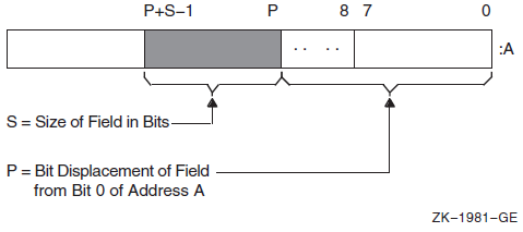
Bit fields are zero-origin, which means that the routine regards the first bit in the field as being the zero position. For more detailed information about VAX bit numbering and data formats, see the VAX Architecture Reference Manual.
The attributes of the bit field are passed to an RTL routine in the form of three arguments in the following order:
pos - Operating system usage: longword_signed
- type: longword integer (signed)
- access: read only
- mechanism: by reference
Bit position relative to the base address. The pos argument
is the address of a signed longword integer that contains this bit position.
size - Operating system usage: byte_unsigned
- type: byte (unsigned)
- access: read only
- mechanism: by reference
Size of the bit field. The size argument is the address of
an unsigned byte that contains this size.
base - Operating system usage: longword_unsigned
- type: longword (unsigned)
- access: read only
- mechanism: by reference
Base address. The base argument contains the address of the
base address.
Example
10      EXTERNAL LONG FUNCTION
                OTS$CVT_TZ_L,           ! Convert hex text to LONG
                LIB$EXTZV               ! Extract zero-ended bit field

20      OPEN "TT:" FOR INPUT AS FILE #1%     ! Open terminal as a file
        INPUT #1%, "HEX>"; HEXIN$            ! Prompt for input
        STAT%=OTS$CVT_TZ_L(HEXIN$, BINARY%)   ! Convert to longword
        IF (STAT% AND 1%) <> 1%               ! Failed?
        THEN
                PRINT "Conversion failed, decimal status ";STAT%
                GO TO 20                      ! Try again
        ELSE
                PRINT HEXIN$,
                PRINT STR$(LIB$EXTZV(N%, 1%, BINARY%));
                        FOR N%=31% to 0% STEP -1%
8.3.2. Integer and Floating-Point Routines
| Entry Point | Function |
|---|---|
|
LIB$EMUL |
Multiplies integers with extended precision |
|
LIB$EDIV |
Divides integers with extended precision |
8.3.3. Queue Access Routines
A queue is a doubly linked list. A run-time library routine specifies a queue entry by its address. Two longwords, a forward link and a backward link, define the location of the entry in relation to the preceding and succeeding entries. A self-relative queue is a queue in which the links between entries are displacements; the two longwords represent the displacements of the current entry's predecessor and successor. The VAX instructions INSQHI, INSQTI, REMQHI, and REMQTI allow you to insert and remove an entry at the head or tail of a self-relative queue. Each queue instruction has a corresponding RTL routine.
The self-relative queue instructions are interlocked and cannot be interrupted, so that other processes cannot insert or remove queue entries while the current program is doing so. Because the operation requires changing two pointers at the same time, a high-level language cannot perform this operation without calling the RTL queue access routines.
When you use these routines, cooperating processes can communicate without further synchronization and without danger of being interrupted, either on a single processor or in a multiprocessor environment. The queue access routines are also useful in an AST environment; they allow you to add or remove an entry from a queue without being interrupted by an asynchronous system trap.
The remove queue instructions (REMQHI or REMQTI) return the address of the removed entry. Some languages, such as BASIC, COBOL, and Fortran, do not provide a mechanism for accessing an address returned from a routine. Further, BASIC and COBOL do not allow routines to be arguments.
| Entry Point | Function |
|---|---|
|
LIB$INSQHI |
Inserts queue entry at head |
|
LIB$INSQTI |
Inserts queue entry at tail |
|
LIB$REMQHI |
Removes queue entry at head |
|
LIB$REMQTI |
Removes queue entry at tail |
Examples
LIB$INSQHI
PSECT = QUEUES, QUAD
INTEGER*4 FUNCTION INSERT_Q (QENTRY)
COMMON/QUEUES/QHEADER
INTEGER*4 QENTRY(10), QHEADER(2)
INSERT_Q = LIB$INSQHI (QENTRY, QHEADER)
RETURN
END COM (QUEUES) QENTRY%(9), QHEADER%(1)
EXTERNAL INTEGER FUNCTION LIB$INSQHI
IF LIB$INSQHI (QENTRY%() BY REF, QHEADER%() BY REF) AND 1%
THEN GOTO 1000
.
.
.
1000 REM INSERTED OKLIB$REMQHI
In Fortran, the address of the removed queue entry can be passed to another routine as an array using the %VAL built-in function.
COMMON/QUEUES/QHEADER
INTEGER*4 QHEADER(2), ISTAT
ISTAT = LIB$REMQHI (QHEADER, ADDR)
IF (ISTAT) THEN
        CALL PROC (%VAL (ADDR)) ! Process removed entry
        GO TO ...
ELSE IF (ISTAT .EQ. %LOC(LIB$_QUEWASEMP)) THEN
                GO TO ...       ! Queue was empty
                ELSE IF
                        ...     ! Secondary interlock failed
END IF
   .
   .
   .
END
SUBROUTINE PROC (QENTRY)
INTEGER*4 QENTRY(10)
   .
   .
   .
RETURN
END
8.3.4. Character String Routines
The character string routines listed in Table 8.6, ''Character String Routines'' give a high-level language program access to the corresponding VAX machine instructions. For a complete description of these instructions, see the VAX Architecture Reference Manual. For each instruction, the VAX Architecture Reference Manual specifies the contents of all the registers after the instruction executes. The corresponding RTL routines do not make the contents of all the registers available to the calling program.
| Entry Point | Function |
|---|---|
|
LIB$LOCC |
Locates a character in a string |
|
LIB$MATCHC |
Returns the relative position of a substring |
|
LIB$SCANC |
Scans characters |
|
LIB$SKPC |
Skips characters |
|
LIB$SPANC |
Spans characters |
|
LIB$MOVC3 |
Moves characters |
|
LIB$MOVC5 |
Moves characters and fills |
|
LIB$MOVTC |
Moves translated characters |
|
LIB$MOVTUC |
Move translated characters until specified character is found |
The VSI OpenVMS RTL String Manipulation (STR$) Manual describes STR$ string manipulation routines.
Example
IDENTIFICATION DIVISION.
PROGRAM-ID.        LIBLOC.

ENVIRONMENT DIVISION.

DATA DIVISION.

WORKING-STORAGE SECTION.

01   SEARCH-STRING  PIC X(26)
                    VALUE "ABCDEFGHIJKLMNOPQRSTUVWXYZ".
01   SEARCH-CHAR    PIC X.
01   IND-POS        PIC 9(9) USAGE IS COMP.
01   DISP-IND       PIC 9(9).

ROUTINE DIVISION.

001-MAIN.
        MOVE SPACE TO SEARCH-CHAR.
        DISPLAY " ".
        DISPLAY "ENTER SEARCH CHARACTER: " WITH NO ADVANCING.
        ACCEPT SEARCH-CHAR.
        CALL "LIB$LOCC"
            USING BY DESCRIPTOR SEARCH-CHAR, SEARCH-STRING
            GIVING IND-POS.
        IF IND-POS = ZERO
            DISPLAY
                "CHAR ENTERED (" SEARCH-CHAR ") NOT A VALID SEARCH CHAR"
            STOP RUN.
        MOVE IND-POS TO DISP-IND.
        DISPLAY
             "SEARCH CHAR (" SEARCH-CHAR ") WAS FOUND IN POSITION "
             DISP-IND.
        GO TO 001-MAIN.
8.3.5. Miscellaneous Instruction Routines
|
Entry Point |
Function |
|---|---|
|
LIB$CALLG |
Calls a routine using an array argument list |
|
LIB$CRC |
Computes a cyclic redundancy check |
|
LIB$CRC_TABLE |
Constructs a table for a cyclic redundancy check |
LIB$CALLG
The LIB$CALLG routine gives your program access to the CALLG instruction. This instruction calls a routine using an argument list stored as an array in memory, as opposed to the CALLS instruction, in which the argument list is pushed on the stack.
LIB$CRC
The LIB$CRC routine allows your high-level language program to use the CRC instruction, which calculates the cyclic redundancy check. This instruction checks the integrity of a data stream by comparing its state at the sending point and the receiving point. Each character in the data stream is used to generate a value based on a polynomial. The values for each character are then added together. This operation is performed at both ends of the data transmission, and the two result values are compared. If the results disagree, then an error occurred during the transmission.
LIB$CRC_TABLE
The LIB$CRC_TABLE routine takes a polynomial as its input and builds the table that LIB$CRC uses to calculate the CRC. You must specify the polynomial to be used.
For more details, see the VAX Architecture Reference Manual.
8.4. Processwide Resource Allocation Routines
Local event flags
BASIC and Fortran logical unit numbers (LUNs)
The resource allocation routines are provided so that user routines can use the processwide resources without conflicting with one another.
In general, you must use run-time library resource allocation routines when your program needs processwide resources. This allows RTL routines supplied by VSI, and user routines that you write to perform together within a process.
If your called routine includes a call to any RTL routine that frees a processwide resource, and that called routine fails to execute normally, the resource will not be freed. Thus, your routine should establish a condition handler that frees the allocated resource before resignaling or unwinding. For information about condition handling, see VSI OpenVMS Programming Concepts Manual, Volume I.
| Entry Point |
Function |
|---|---|
|
LIB$FREE_LUN |
Deallocates a specific logical unit number |
|
LIB$GET_LUN |
Allocates next arbitrary logical unit number |
|
LIB$FREE_EF |
Frees a local event flag |
|
LIB$GET_EF |
Allocates a local event flag |
|
LIB$RESERVE_EF |
Reserves a local event flag |
8.4.1. Allocating Logical Unit Numbers
BASIC and Fortran use a logical unit number (LUN) to define the file or device a program uses to perform input and output. For a routine to be modular, it does not need to know the LUNs being used by other routines that are running at the same time. For this reason, logical units are allocated and deallocated at run time. You can use LIB$GET_LUN and LIB$FREE_LUN to obtain the next available number. This ensures that your BASIC or Fortran routine does not use a logical unit that is already being used by a calling program. Therefore, you should use this routine whenever your program calls or is called by another program that also allocates LUNs. Logical unit numbers 100 to 119 are available to modular routines through these entry points.
To allocate an LUN, call LIB$GET_LUN and use the value returned as the LUN for your I/O statements. If no LUNs are available, an error status is returned and the logical unit is set to -1. When the program unit exits, it should use LIB$FREE_LUN to free any LUNs that have been allocated by LIB$GET_LUN. If it does not free any LUNs, the available pool of numbers is freed for use.
If your called routine contains a call to LIB$FREE_LUN to free the LUNs upon exit, and your routine fails to execute normally, the LUNs will not be freed. For this reason, you should make sure to establish a condition handler to call LIB$FREE_LUN before resignaling or unwinding. Otherwise, the allocated LUN is lost until the image exits.
8.4.2. Allocating Event Flag Numbers
The LIB$GET_EF and LIB$FREE_EF routines operate in a similar way to LIB$GET_LUN and LIB$FREE_LUN. They cause local event flags to be allocated and deallocated at run time, so that your routine remains independent of other routines executing in the same process.
Local event flags numbered 32 to 63 are available to your program. These event flags allow routines to communicate and synchronize their operations. If you use a specific event flag in your routine, another routine may attempt to use the same flag, and the flag will no longer function as expected. Therefore, you should call LIB$GET_EF to obtain the next arbitrary event flag and LIB$FREE_EF to return it to the storage pool. You can obtain a specific event flag number by calling LIB$RESERVE_EF. This routine takes as its argument the event flag number to be allocated.
For information about using event flags, see VSI OpenVMS Programming Concepts Manual, Volume I.
8.5. Performance Measurement Routines
|
Entry Point |
Function |
|---|---|
|
LIB$INIT_TIMER |
Stores the values of the specified times and counts in units of static or heap storage, depending on the value of the routine's argument |
|
LIB$SHOW_TIMER |
Obtains and formats for output the specified times and counts that are accumulated since the last call to LIB$INIT_TIMER |
|
LIB$STAT_TIMER |
Obtains one of the times and counts since the last call to LIB$INIT_TIMER and returns it as an unsigned quadword or longword |
|
LIB$FREE_TIMER |
Frees the storage allocated by LIB$INIT_TIMER |
Elapsed time
CPU time
Buffered I/O count
Direct I/O count
Page faults
The LIB$SHOW_TIMER and LIB$STAT_TIMER routine are relatively simple tools for testing the performance of a new application. To obtain more detailed information, use the system services SYS$GETTIM (Get Time) and SYS$GETJPI (Get Job/Process Information).
The simplest way to use the run-time library routines is to call LIB$INIT_TIMER with no arguments at the beginning of the portion of code to be monitored. This causes the statistics to be placed in OWN storage. To get the statistics from OWN storage, call LIB$SHOW_TIMER (with no arguments) at the end of the portion of code to be monitored.
If you want a particular statistic, you must include a
codeargument with a call to
LIB$SHOW_TIMER or
LIB$STAT_TIMER.LIB$SHOW_TIMER
returns the specified statistic(s) in formatted form and sends them to
SYS$OUTPUT. On each call,
LIB$STAT_TIMER returns one statistic to the calling program
as an unsigned longword or quadword value.
Code Argument in
LIB$SHOW_TIMER and
LIB$STAT_TIMER'' shows the codeargument in
LIB$SHOW_TIMER or
LIB$STAT_TIMER.Code Argument in
LIB$SHOW_TIMER and
LIB$STAT_TIMER|
Argument Value |
Meaning |
LIB$SHOW_TIMER Format |
LIB$STAT_TIMER Format |
|---|---|---|---|
|
1 |
Elapsed real time |
dddd hh:mm:ss.cc |
Quadword, in system time format |
|
2 |
Elapsed CPU time |
hhhh:mm:ss.cc |
Longword, in 10-millisecond increments |
|
3 |
Number of buffered I/O operations |
nnnn |
Longword |
|
4 |
Number of direct I/O operations |
nnnn |
Longword |
|
5 |
Number of page faults |
nnnn |
Longword |
When you call LIB$INIT_TIMER, you must use the optional
handler argument only if you want to keep several sets of
statistics simultaneously. This argument points to a block in heap storage where the
statistics are to be stored. You need to call LIB$FREE_TIMER
only if you have specified handler in
LIB$INIT_TIMER and you want to deallocate all heap storage
resources. In most cases, the implicit deallocation when the image exits is
sufficient.
The LIB$STAT_TIMER routine returns only one of the five statistics for each call, and it returns that statistic in the form of an unsigned quadword or longword. LIB$SHOW_TIMER returns the virtual address of the stored information, which BASIC cannot directly access. Therefore, a BASIC program must call LIB$STAT_TIMER and format the returned statistics, as the following example demonstrates.
Example
100    EXTERNAL INTEGER FUNCTION LIB$INIT_TIMER
       EXTERNAL INTEGER FUNCTION LIB$STAT_TIMER
       EXTERNAL INTEGER FUNCTION LIB$FREE_TIMER
       EXTERNAL INTEGER CONSTANT SS$_NORMAL

200    DECLARE LONG COND_VALUE, RANDOM_SLEEP
       DECLARE LONG CODE, HANDLE
       DECLARE STRING TIME_BUFFER
       HANDLE = 0
       TIME_BUFFER = SPACE$(50%)

300    MAP (TIMER) LONG ELAPSED_TIME, FILL
       MAP (TIMER) LONG CPU_TIME
       MAP (TIMER) LONG BUFIO
       MAP (TIMER) LONG DIRIO
       MAP (TIMER) LONG PAGE_FAULTS

400    PRINT "This program returns information about:"
       PRINT "Elapsed time (1)"
       PRINT "CPU time (2)"
       PRINT "Buffered I/O (3)"
       PRINT "Direct I/O (4)"
       PRINT "Page faults (5)"
       PRINT "Enter zero to exit program"
       PRINT "Enter a number from one to"
       PRINT "five for performance information"
       INPUT "One, two, three, four, or five"; CODE
       PRINT

450    GOTO 32766 IF CODE = 0

500    COND_VALUE = LIB$INIT_TIMER( HANDLE )

550    IF (COND_VALUE <> SS$_NORMAL) THEN PRINT @
         "Error in initialization"
              GOTO 32767

650    A = 0                !
       FOR I = 1 to 100000  ! This code merely uses some CPU time
       A = A + 1            !
       NEXT I               !

700    COND_VALUE = LIB$STAT_TIMER( CODE, ELAPSED_TIME, HANDLE )

750    IF (COND_VALUE <> SS$_NORMAL) THEN PRINT @
         "Error in statistics routine"
              GOTO 32767

800    GOTO 810 IF CODE <> 1%
       CALL SYS$ASCTIM ( , TIME_BUFFER, ELAPSED_TIME, 1% BY VALUE)
       PRINT "Elapsed time: "; TIME_BUFFER

810    PRINT "CPU time in seconds: "; .01 * CPU_TIME IF CODE = 2%
       PRINT "Buffered I/O: ";BUFIO IF CODE = 3%
       PRINT "Direct I/O: ";DIRIO IF CODE = 4%
       PRINT "Page faults: ";PAGE_FAULTS IF CODE = 5%
       PRINT

900    GOTO 400

32765  COND_VALUE = LIB$FREE_TIMER( HANDLE )
32766  IF (COND_VALUE <> SS$_NORMAL) THEN PRINT @
         "Error in LIB$FREE_TIMER"
                        GOTO 32767

32767  END
For information about using system time, see Chapter 11, "System Time Operations".
8.6. Output Formatting Control Routines
| Entry Point | Function |
|---|---|
|
LIB$CURRENCY |
Defines the default currency symbol for process |
|
LIB$DIGIT_SEP |
Defines the default digit separator for process |
|
LIB$LP_LINES |
Defines the process default size for a printed page |
|
LIB$RADIX_POINT |
Defines the process default radix point character |
|
$ |
SYS$CURRENCY |
|
, |
SYS$DIGIT_SEP |
|
. |
SYS$RADIX_POINT |
|
66 |
SYS$LP_LINES |
For example, if you want to use the British pound sign (£)as the currency symbol within your process, but you want to leave the dollar sign ($) as the system default, define SYS$CURRENCY to be in your process logical name table. Then, any calls to LIB$CURRENCY within your process return "£", while any calls outside your process return "$".
You can use LIB$LP_LINES to monitor the current default length of the line printer page. You can also supply your own default length for the current process. United States standard paper size permits 66 lines on each physical page.
If you are writing programs for a utility that formats a listing file to be printed on a line printer, you can use LIB$LP_LINES to make your utility independent of the default page length. Your program can use LIB$LP_LINES to obtain the current length of the page. It can then calculate the number of lines of text per page by subtracting the lines used for margins and headings.
Three lines for the top margin
Three lines for the bottom margin
- Three lines for listing heading information, consisting of:
Language-processor identification line
Source program identification line
One blank line
8.7. Miscellaneous Interface Routines
|
Entry Point |
Function |
|---|---|
|
LIB$AST_IN_PROG |
Indicates whether an asynchronous system trap is in progress |
|
LIB$ASN_WTH_MBX |
Assigns an I/O channel and associates it with a mailbox |
|
LIB$CREATE_DIR |
Creates a directory or subdirectory |
|
LIB$FIND_IMAGE_SYMBOL |
Reads a global symbol from the shareable image file and dynamically activates a shareable image into the P0 address space of a process |
|
LIB$ADDX |
Performs addition on signed two's complement integers of arbitrary length (multiple-precision addition) |
|
LIB$SUBX |
Performs subtraction on signed two's complement integers of arbitrary length (multiple-precision subtraction) |
|
LIB$FILE_SCAN |
Finds file names given OpenVMS RMS file access block (FAB) |
|
LIB$FILE_SCAN_END |
Specifies end-of-file scan |
|
LIB$FIND_FILE |
Finds file names given string |
|
LIB$FIND_FILE_END |
Specifies the end-of-find file |
|
LIB$INSERT_TREE |
Inserts an element in a binary tree |
|
LIB$LOOKUP_TREE |
Finds an element in a binary tree |
|
LIB$TRAVERSE_TREE |
Traverses a binary tree |
|
LIB$GET_COMMON |
Gets a record from the process's COMMON storage area |
|
LIB$PUT_COMMON |
Puts a record to the process's COMMON storage area |
8.7.1. Indicating Asynchronous System Trap in Progress
An asynchronous system trap (AST) is a mechanism for providing a software interrupt when an external event occurs, such as when a user presses the Ctrl/C key sequence. When an external event occurs, the operating system interrupts the execution of the current process and calls a routine that you supply. While that routine is active, the AST is said to be in progress, and the process is said to be executing at AST level. When your AST routine returns control to the original process, the AST is no longer active and execution continues where it left off.
The LIB$AST_IN_PROG routine indicates to the calling program whether an AST is currently in progress. Your program can call LIB$AST_IN_PROG to determine whether it is executing at AST level, and then take appropriate action. This routine is useful if you are writing AST-reentrant code.
For information about using ASTs, see VSI OpenVMS Programming Concepts Manual, Volume I.
8.7.2. Create a Directory or Subdirectory
The LIB$CREATE_DIR routine creates a directory or a subdirectory. The calling program must specify the directory specification in standard OpenVMS RMS format. This directory specification may also contain a disk specification.
The user identification code (UIC) of the owner of the created directory or subdirectory
The protection enable mask
The protection value mask
The maximum number of versions allowed for files created in this directory or subdirectory
The relative volume number within the volume set on which the directory or subdirectory is created
See the VSI OpenVMS RTL Library (LIB$) Manual for a complete description of LIB$CREATE_DIR.
8.7.3. File Searching Routines
When you call LIB$FILE_SCAN with a wildcard file specification and an action routine, the routine calls the action routine for each file or error, or both, found in the wildcard sequence. LIB$FILE_SCAN allows the search sequence to continue even though certain errors are present.
When you call LIB$FIND_FILE with a wildcard file specification, it finds the next file specification that matches the wildcard specification.
The default specification.
The related specification.
The OpenVMS RMS secondary status value from a failing RMS operation.
A longword containing two flag bits. If bit 1 is set, LIB$FIND_FILE performs temporary defaulting for multiple input files and the related specification argument is ignored. See the VSI OpenVMS RTL Library (LIB$) Manual for a complete description of LIB$FIND_FILE in template format.
The LIB$FIND_FILE_END routine is called once after each call to LIB$FIND_FILE in interactive use. LIB$FIND_FILE_END prevents the temporary default values retained by the previous call to LIB$FIND_FILE from affecting the next file specification.
$ COPY [smith]A,B,C *
The LIB$FILE_SCAN_END routine is called once after each sequence of calls to LIB$FILE_SCAN.LIB$FILE_SCAN_END performs a parse of the null string to deallocate saved OpenVMS RMS context and to prevent the temporary default values retained by the previous call to LIB$FILE_SCAN from affecting the next file specification. For instance, in the previous example, LIB$FILE_SCAN_END should be called after the C file specification is parsed, so that specifications from the $COPY files do not affect file specifications in subsequent commands.
%TITLE 'FILE_EXAMPLE1 - Sample program using LIB$FIND_FILE'
MODULE FILE_EXAMPLE1(           ! Sample program using LIB$FIND_FILE
                IDENT = '1-001',
                MAIN = EXAMPLE_START
                ) =
BEGIN

%SBTTL 'Declarations'
!+
! SWITCHES:
!-

SWITCHES ADDRESSING_MODE (EXTERNAL = GENERAL, NONEXTERNAL = WORD_RELATIVE);

!+
! TABLE OF CONTENTS:
!-

FORWARD ROUTINE
    EXAMPLE_START;                              ! Main program

!+
! INCLUDE FILES:
!-

LIBRARY 'SYS$LIBRARY:STARLET.L32';              ! System symbols

!+
! Define facility-specific messages from shared system messages.
!-
$SHR_MSGDEF(CLI,3,LOCAL,
                (PARSEFAIL,WARNING));
!+
! EXTERNAL REFERENCES:
!-

EXTERNAL ROUTINE
    LIB$GET_INPUT,                             ! Read from SYS$INPUT
    LIB$FIND_FILE,                             ! Wildcard scanning routine
    LIB$FIND_FILE_END,          ! End find file
    LIB$PUT_OUTPUT,                            ! Write to SYS$OUTPUT
    STR$COPY_DX;                               ! String copier

LITERAL
    TRUE = 1,                                  ! Success
    FALSE = 0;                                 ! Failure

%SBTTL 'EXAMPLE_START - Sample program main routine';
ROUTINE EXAMPLE_START =
BEGIN
!+
! This program reads a file specification and default file
! specification from SYS$INPUT.  It then prints all the files that
! match that specification and prompts for another file specification.
! After the first file specification no default specification is requested,
! and the previous resulting file specification becomes the related
! file specification.
!-
LOCAL
    LINEDESC : $BBLOCK[DSC$C_S_BLN],     ! String desc. for input line
    RESULT_DESC : $BBLOCK[DSC$C_S_BLN],  ! String desc. for result file
    CONTEXT,                             ! LIB$FIND_FILE context pointer
    DEFAULT_DESC : $BBLOCK[DSC$C_S_BLN], ! String desc. for default spec
    RELATED_DESC : $BBLOCK[DSC$C_S_BLN], ! String desc. for related spec
    HAVE_DEFAULT,
    STATUS;
!+
! Make all string descriptors dynamic.
!-
CH$FILL(0,DSC$C_S_BLN,LINEDESC);
LINEDESC[DSC$B_CLASS] = DSC$K_CLASS_D;
CH$MOVE(DSC$C_S_BLN,LINEDESC,RESULT_DESC);
CH$MOVE(DSC$C_S_BLN,LINEDESC,DEFAULT_DESC);
CH$MOVE(DSC$C_S_BLN,LINEDESC,RELATED_DESC);
HAVE_DEFAULT = FALSE;
CONTEXT = 0;
!+
! Read file specification, default file specification, and
! related file specification.
!-

WHILE (STATUS = LIB$GET_INPUT(LINEDESC,
                $DESCRIPTOR('FILE SPECIFICATION: '))) NEQ RMS$_EOF
DO BEGIN
    IF NOT .STATUS
        THEN SIGNAL_STOP(.STATUS);
    !+
    ! If default file specification was not obtained, do so now.
    !-
    IF NOT .HAVE_DEFAULT
    THEN BEGIN
        STATUS = LIB$GET_INPUT(DEFAULT_DESC,
                $DESCRIPTOR('DEFAULT FILE SPECIFICATION: '));
        IF NOT .STATUS
            THEN SIGNAL_STOP(.STATUS);
        HAVE_DEFAULT = TRUE;
        END;


    !+
    ! CALL LIB$FIND_FILE until RMS$_NMF (no more files) is returned.
    ! If an error other than RMS$_NMF is returned, it is signaled.
    ! Print out the file specification if the call is successful.
    !-
    WHILE (STATUS = LIB$FIND_FILE(LINEDESC,RESULT_DESC,CONTEXT,
                        DEFAULT_DESC,RELATED_DESC)) NEQ RMS$_NMF
    DO IF NOT .STATUS
        THEN SIGNAL(CLI$_PARSEFAIL,1,RESULT_DESC,.STATUS)
        ELSE LIB$PUT_OUTPUT(RESULT_DESC);
    !+
    ! Make this resultant file specification the related file
    ! specification for next file.
    !-
    STR$COPY_DX(RELATED_DESC,LINEDESC);
    END;                                    ! End of loop
                                            !  reading file specification

!+
! Call LIB$FIND_FILE_END to deallocate the virtual memory used by LIB$FIND_FILE.
! Note that we do this outside of the loop.  Since the MULTIPLE bit of the
! optional user flags argument to LIB$FIND_FILE wasn't used, it is not
! necessary to call LIB$FIND_FILE_END after each call to LIB$FIND_FILE.
! (The MULTIPLE bit would have caused temporary defaulting for multiple input
!  files.)
!-
STATUS = LIB$FIND_FILE_END (CONTEXT);

IF NOT .STATUS
    THEN SIGNAL_STOP (.STATUS);

RETURN TRUE
END;                                        ! End of main program
END                                         ! End of module

ELUDOM
%TITLE 'FILE_EXAMPLE2 - Sample program using LIB$FILE_SCAN'
MODULE FILE_EXAMPLE1(             ! Sample program using LIB$FILE_SCAN
        IDENT = '1-001',
        MAIN = EXAMPLE_START
        ) =
BEGIN

%SBTTL 'Declarations'
!+
! SWITCHES:
!-

SWITCHES ADDRESSING_MODE (EXTERNAL = GENERAL,
        NONEXTERNAL = WORD_RELATIVE);

!+
! TABLE OF CONTENTS:
!-

FORWARD ROUTINE
    EXAMPLE_START,          ! Main program
    SUCCESS_RTN,            ! Success action routine
    ERROR_RTN;              ! Error action routine

!+
! INCLUDE FILES:
!-

LIBRARY 'SYS$LIBRARY:STARLET.L32';      ! System symbols

!+
! Define VMS block structures (BLOCK[,BYTE]).
!-
STRUCTURE
    BBLOCK [O, P, S, E; N] =
                [N]
                (BBLOCK + O) <P, S, E>;
!+
! EXTERNAL REFERENCES:
!-

EXTERNAL ROUTINE
    LIB$GET_INPUT,             ! Read from SYS$INPUT
    LIB$FILE_SCAN,             ! Wildcard scanning routine
    LIB$FILE_SCAN_END,         ! End of file scan
    LIB$PUT_OUTPUT;            ! Write to SYS$OUTPUT

%SBTTL 'EXAMPLE_START - Sample program main routine';
ROUTINE EXAMPLE_START =
BEGIN
!+
! This program reads the file specification, default file specification,
! and related file specification from SYS$INPUT and then displays on
! SYS$OUTPUT all files which match the specification.
!-
LOCAL
    RESULT_BUFFER : VECTOR[NAM$C_MAXRSS,BYTE], !Buffer for resultant
                                               !  name string
    EXPAND_BUFFER : VECTOR[NAM$C_MAXRSS,BYTE], !Buffer for expanded
                                               !  name string
    LINEDESC : BBLOCK[DSC$C_S_BLN],            !String descriptor
                                               !  for input line
    RESULT_DESC : BBLOCK[DSC$C_S_BLN],         !String descriptor
                                               !  for result file
    DEFAULT_DESC : BBLOCK[DSC$C_S_BLN],        !String descriptor
                                               !  for default specification
    RELATED_DESC : BBLOCK[DSC$C_S_BLN],        !String descriptor
                                               !  for related specification
    IFAB : $FAB_DECL,                          !FAB for file_scan
    INAM : $NAM_DECL,                          !  and a NAM block
    RELNAM : $NAM_DECL,                        !  and a related NAM block
    STATUS;
!+
! Make all descriptors dynamic.
!-
CH$FILL(0,DSC$C_S_BLN,LINEDESC);
LINEDESC[DSC$B_CLASS] = DSC$K_CLASS_D;
CH$MOVE(DSC$C_S_BLN,LINEDESC,RESULT_DESC);
CH$MOVE(DSC$C_S_BLN,LINEDESC,DEFAULT_DESC);
CH$MOVE(DSC$C_S_BLN,LINEDESC,RELATED_DESC);
!+
! Read file specification, default file specification, and related
! file specification
!-
STATUS = LIB$GET_INPUT(LINEDESC,
                $DESCRIPTOR('File specification: '));
IF NOT .STATUS
    THEN SIGNAL_STOP(.STATUS);
STATUS = LIB$GET_INPUT(DEFAULT_DESC,
                $DESCRIPTOR('Default file specification: '));
IF NOT .STATUS
    THEN SIGNAL_STOP(.STATUS);
STATUS = LIB$GET_INPUT(RELATED_DESC,
                $DESCRIPTOR('Related file specification: '));
IF NOT .STATUS
    THEN SIGNAL_STOP(.STATUS);
!+
! Initialize the FAB, NAM, and related NAM blocks.
!-
$FAB_INIT(FAB=IFAB,
        FNS=.LINEDESC[DSC$W_LENGTH],
        FNA=.LINEDESC[DSC$A_POINTER],
        DNS=.DEFAULT_DESC[DSC$W_LENGTH],
        DNA=.DEFAULT_DESC[DSC$A_POINTER],
        NAM=INAM);

$NAM_INIT(NAM=INAM,
        RSS=NAM$C_MAXRSS,
        RSA=RESULT_BUFFER,
        ESS=NAM$C_MAXRSS,
        ESA=EXPAND_BUFFER,
        RLF=RELNAM);

$NAM_INIT(NAM=RELNAM);
RELNAM[NAM$B_RSL] = .RELATED_DESC[DSC$W_LENGTH];
RELNAM[NAM$L_RSA] = .RELATED_DESC[DSC$A_POINTER];
!+
! Call LIB$FILE_SCAN.  Note that errors need not be checked
! here because LIB$FILE_SCAN calls error_rtn for all errors.
!-
LIB$FILE_SCAN(IFAB,SUCCESS_RTN,ERROR_RTN);

!+
! Call LIB$FILE_SCAN_END to deallocate virtual memory used for
! file scan structures.
!-
STATUS = LIB$FILE_SCAN_END (IFAB);

IF NOT .STATUS
    THEN SIGNAL_STOP (.STATUS);

RETURN 1
END;                                                ! End of main program

ROUTINE SUCCESS_RTN (IFAB : REF BBLOCK) =
BEGIN
!+
! This routine is called by LIB$FILE_SCAN for each file that it
! successfully finds in the search sequence.
!
! Inputs:
!
!        IFAB    Address of a fab
!
! Outputs:
!
!        file specification printed on SYS$OUTPUT
!-
LOCAL
    DESC : BBLOCK[DSC$C_S_BLN];    ! A local string descriptor
BIND
    INAM = .IFAB[FAB$L_NAM] : BBLOCK;    ! Find NAM block
                                         !   from pointer in FAB
CH$FILL(0,DSC$C_S_BLN,DESC);             ! Make static
                                         !   string descriptor
DESC[DSC$W_LENGTH] = .INAM[NAM$B_RSL];   ! Get string length
                                         !   from NAM block
DESC[DSC$A_POINTER] = .INAM[NAM$L_RSA];  ! Get pointer to the string
RETURN LIB$PUT_OUTPUT(DESC)              ! Print name on SYS$OUTPUT
                                         !   and return
END;

ROUTINE ERROR_RTN (IFAB : REF BBLOCK) =
BEGIN
!+
! This routine is called by LIB$FILE_SCAN for each file specification that
! produces an error.
!
! Inputs:
!
!        ifab     Address of a fab
!
! Outputs:
!
!        Error message is signaled
!-
LOCAL
    DESC : BBLOCK[DSC$C_S_BLN];            ! A local string descriptor

BIND
    INAM = .IFAB[FAB$L_NAM] : BBLOCK;      ! Get NAM block pointer
                                           !   from FAB

CH$FILL(0,DSC$C_S_BLN,DESC);               ! Create static
                                           !   string descriptor
DESC[DSC$W_LENGTH] = .INAM[NAM$B_RSL];
DESC[DSC$A_POINTER] = .INAM[NAM$L_RSA];
!+
! Signal the error using the shared message PARSEFAIL
! and the CLI facility code.  The second part of the SIGNAL
! is the RMS STS and STV error codes.
!-
RETURN SIGNAL((SHR$_PARSEFAIL+3^16),1,DESC,
                .IFAB[FAB$L_STS],.IFAB[FAB$L_STV])

END;
END                   ! End of module

ELUDOM
8.7.4. Inserting an Entry into a Balanced Binary Tree
LIB$INSERT_TREE adds an entry to a balanced binary tree.
LIB$LOOKUP_TREE looks up an entry in a balanced binary tree.
LIB$TRAVERSE_TREE calls an action routine for each node in the tree.
Example
The first subroutine allocates virtual memory for a node.
The second subroutine compares a key with a node.
The third subroutine is called during the tree traversal. It prints out the left and right subtree pointers, the current node balance, and the name of the node.
%TITLE 'TREE_EXAMPLE   - Sample program using binary tree routines'
MODULE TREE_EXAMPLE(                      ! Sample program using trees
                IDENT = '1-001',
                MAIN = TREE_START
                ) =
BEGIN

%SBTTL 'Declarations'
!+
! SWITCHES:
!-
SWITCHES ADDRESSING_MODE (EXTERNAL = GENERAL, NONEXTERNAL = WORD_RELATIVE);

!+
! LINKAGES:
!
!      NONE
!
! TABLE OF CONTENTS:
!-

FORWARD ROUTINE
    TREE_START,                     ! Main program
    ALLOC_NODE,                     ! Allocate memory for a node
    COMPARE_NODE,                   ! Compare two nodes
    PRINT_NODE;                     ! Print a node (action routine
                                    !  for LIB$TRAVERSE_TREE)

!+
! INCLUDE FILES:
!-

LIBRARY 'SYS$LIBRARY:STARLET.L32';              ! System symbols

!+
! Define VMS block structures (BLOCK[,BYTE]).
!-
STRUCTURE
    BBLOCK [O, P, S, E; N] =
                [N]
                (BBLOCK + O) <P, S, E>;
!+
! MACROS:
!-
MACRO
    NODE$L_LEFT = 0,0,32,0%,         ! Left subtree pointer in node
    NODE$L_RIGHT = 4,0,32,0%,        ! Right subtree pointer
    NODE$W_BAL = 8,0,16,0%,          ! Balance this node
    NODE$B_NAMLNG = 10,0,8,0%,       ! Length of name in this node
    NODE$T_NAME = 11,0,0,0%;         ! Start of name (variable length)

LITERAL
    NODE$C_LENGTH = 11;              ! Length of fixed part of node

!+
! EXTERNAL REFERENCES:
!-

EXTERNAL ROUTINE
    LIB$GET_INPUT,                   ! Read from SYS$INPUT
    LIB$GET_VM,                      ! Allocate virtual memory
    LIB$INSERT_TREE,                 ! Insert into binary tree
    LIB$LOOKUP_TREE,                 ! Lookup in binary tree
    LIB$PUT_OUTPUT,                  ! Write to SYS$OUTPUT
    LIB$TRAVERSE_TREE,               ! Traverse a binary tree
    STR$UPCASE,                      ! Convert string to all uppercase
    SYS$FAO;                         ! Formatted ASCII output routine

%SBTTL 'TREE_START - Sample program main routine';
ROUTINE TREE_START =
BEGIN
!+
! This program reads from SYS$INPUT and stores each data line
! as an entry in a binary tree.  When end-of-file character (CTRL/Z)
! is entered, the tree will be printed in sorted order.
!-
LOCAL
    NODE : REF BBLOCK,              ! Address of allocated node
    TREEHEAD,                       ! List head of binary tree
    LINEDESC : BBLOCK[DSC$C_S_BLN], ! String descriptor for input line
    STATUS;

TREEHEAD = 0;                           ! Zero binary tree head
CH$FILL(0,DSC$C_S_BLN,LINEDESC);        ! Make a dynamic descriptor
LINEDESC[DSC$B_CLASS] = DSC$K_CLASS_D;  ! ...
!+
! Read input lines until end of file seen.
!-
WHILE (STATUS = LIB$GET_INPUT(LINEDESC,           ! Read input line
                        $DESCRIPTOR('Text: ')))   !  with this prompt
                NEQ RMS$_EOF
DO IF NOT .STATUS                            ! Report any errors found
        THEN SIGNAL(.STATUS)
        ELSE BEGIN
            STR$UPCASE(LINEDESC,LINEDESC);   ! Convert string
                                             !  to uppercase
            IF NOT (STATUS = LIB$INSERT_TREE(
                        TREEHEAD,       ! Insert good data into the tree
                        LINEDESC,       ! Data to insert
                        %REF(1),        ! Insert duplicate entries
                        COMPARE_NODE,   ! Addr. of compare routine
                        ALLOC_NODE,     ! Addr. of node allocation routine
                        NODE,           ! Return addr. of
                        0))             !   allocated node here
                THEN SIGNAL(.STATUS);
            END;
!+
! End of file character encountered.  Print the whole tree and exit.
!-
IF NOT (STATUS = LIB$TRAVERSE_TREE(
                        TREEHEAD,       ! Listhead of tree
                        PRINT_NODE,     ! Action routine to print a node
                        0))
    THEN SIGNAL(.STATUS);

RETURN SS$_NORMAL
END;                                     ! End of routine tree_start

ROUTINE ALLOC_NODE (KEYDESC,RETDESC,CONTEXT) =
BEGIN
!+
! This routine allocates virtual memory for a node.
!
! INPUTS:
!
!      KEYDESC                Address of string descriptor for key
!                              (this is the linedesc argument passed
!                              to LIB$INSERT_TREE)
!      RETDESC                Address of location to return address of
!                              allocated memory
!      CONTEXT                Address of user context argument passed
!                              to LIB$INSERT_TREE (not used in this
!                              example)
!
! OUTPUTS:
!
!        Memory address returned in longword pointed to by retdesc
!-
MAP
    KEYDESC : REF BBLOCK,
    RETDESC : REF VECTOR[,LONG];

LOCAL
    NODE : REF BBLOCK,
    STATUS;

STATUS = LIB$GET_VM(%REF(NODE$C_LENGTH+.KEYDESC[DSC$W_LENGTH]),NODE);
IF NOT .STATUS
    THEN RETURN .STATUS
    ELSE BEGIN
        NODE[NODE$B_NAMLNG] = .KEYDESC[DSC$W_LENGTH];  ! Set name length
        CH$MOVE(.KEYDESC[DSC$W_LENGTH],                ! Copy in the name
                .KEYDESC[DSC$A_POINTER],
                NODE[NODE$T_NAME]);
        RETDESC[0] = .NODE;                    ! Return address to caller
        END;
RETURN .STATUS

END;


ROUTINE COMPARE_NODE (KEYDESC,NODE,CONTEXT) =
BEGIN
!+
! This routine compares a key with a node.
!
! INPUTS:
!
!       KEYDESC           Address of string descriptor for new key
!                          (This is the linedesc argument passed to
!                          LIB$INSERT_TREE)
!       NODE              Address of current node
!       CONTEXT           User context data (Not used in this example)
!-
MAP
    KEYDESC : REF BBLOCK,
    NODE : REF BBLOCK;

RETURN CH$COMPARE(.KEYDESC[DSC$W_LENGTH],          ! Compare key with
                                                   !  current node
                        .KEYDESC[DSC$A_POINTER],
                        .NODE[NODE$B_NAMLNG],
                        NODE[NODE$T_NAME])

END;

ROUTINE PRINT_NODE (NODE,CONTEXT) =
BEGIN
!+
! This routine is called during the tree traversal.  It
! prints out the left and right subtree pointers, the
! current node balance, and the name of the node.
!-
MAP
    NODE : REF BBLOCK;

LOCAL
    OUTBUF : BBLOCK[512],                   ! FAO output buffer
    OUTDESC : BBLOCK[DSC$C_S_BLN],          ! Output buffer descriptor
    STATUS;
CH$FILL(0,DSC$C_S_BLN,OUTDESC);             ! Zero descriptor
OUTDESC[DSC$W_LENGTH] = 512;
OUTDESC[DSC$A_POINTER] = OUTBUF;
IF NOT (STATUS = SYS$FAO($DESCRIPTOR('!XL !XL !XL !XW !AC'),
                        OUTDESC,OUTDESC,
                        .NODE,.NODE[NODE$L_LEFT],
                        .NODE[NODE$L_RIGHT],
                        .NODE[NODE$W_BAL],
                        NODE[NODE$B_NAMLNG]))
    THEN SIGNAL(.STATUS)
    ELSE BEGIN
        STATUS = LIB$PUT_OUTPUT(OUTDESC);      ! Output the line
        IF NOT .STATUS
            THEN SIGNAL(.STATUS);
        END;

RETURN SS$_NORMAL

END;
END                                       ! End of module TREE_EXAMPLE

ELUDOM
Chapter 9. Using Cross-Reference Routines
The cross-reference routines are contained in a separate, shareable image capable of creating a cross-reference analysis of symbols. They accept cross-reference data, summarize it, and format it for output. Three facilities that use the cross-reference routines are the VMS Linker, the MACRO assembler, and the Librarian. They are sufficiently general, however, to be used by any native-mode utility.
|
Entry Point |
Function |
|---|---|
|
LIB$CRF_INS_KEY |
Inserts key information |
|
LIB$CRF_INS_REF |
Inserts reference information |
|
LIB$CRF_OUTPUT |
Summarizes and formats cross-reference information |
The interface to the cross-reference routines is by way of a set of control blocks, format definition tables, and a set of callable entry points. Macros are provided for assembly language and BLISS initialization of the control blocks and format definition tables.
9.1. How to Use the Cross-Reference Routines
Define a table of control information, using the $CRFCTLTABLE macro.
Define each field of the output line, using the $CRFFIELD macro.
Specify the end of each set of macros that define a field in the output line, using the $CRFFIELDEND macro.
- Provide data by calling one of the two following cross-reference entry points:
LIB$CRF_INS_KEY inserts an entry for the specified key in the specified symbol table.
LIB$CRF_INS_REF inserts a reference to a key in the specified symbol table.
Call LIB$CRF_OUTPUT, the cross-reference output routine, to summarize and format the data.
Supply a routine that the output routine calls to print each line in the output file. Because you supply this routine, you can control the number of lines per page and the header lines.
Figure 9.1, ''Using Cross-Reference Routines'' illustrates the steps required in using the cross-reference routines.
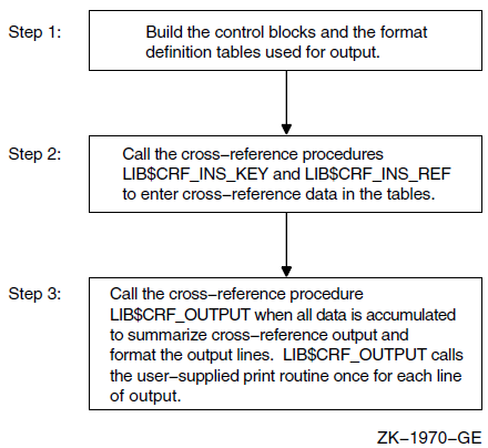
$CRFCTLTABLE defines a table of control information.
$CRFFIELD defines each field of the output format definition table. Multiple $CRFFIELD macro instructions can be issued in defining one particular field.
$CRFFIELDEND ends a set of $CRFFIELD macro instructions (a format table).
9.2. $CRFCTLTABLE Macro
$CRFCTLTABLE initializes a cross-reference control table. Your program must issue one $CRFCTLTABLE macro for each cross-reference table you build. You can accumulate information for more than one cross-reference table at a time. For this reason, you must define a table for each set of cross-references, and include the address of that table each time you call a cross-reference routine to insert data.
label: $CRFCTLTABLE
         keytype, output, error, memexp, key1table, key2table,
         val1table, val2table, ref1table, ref2table
label The address of the control table. You must specify a control table address in all calls to the cross-reference routines.
keytype |
ASCIC |
Keys are counted ASCII strings, with a maximum of 255 characters (symbol name). |
|
BIN_U32 |
Keys are 32-bit unsigned binary values. The binary-to-ASCII conversion is done by $FAO using the format string for the KEY1 field. |
|
ASCIZ |
Keys are zero-terminated ASCII strings. (Alpha and I64 Only) |
|
BIN_U64 |
Keys are 64-bit unsigned binary values. The binary-to-ASCII conversion is done by $FAO using the format string for the KEY1 field. (Alpha and I64 Only) |
output The address of the routine that you supply to print a formatted output line. The output line is passed to the output routine by descriptor.
error The address of an error routine to execute if the called cross-reference routine encounters an error. The error code (longword) is passed to the error routine by value. In other words, it is a copy of the constant on the stack. A value of zero indicates that no error routine is supplied.
memexp The number of pages by which to expand region when needed. The default is 50.
key1table The address of the field descriptor table for the KEY1 field. A value of zero indicates that the field is not to be included in the output line.
The remaining arguments provide the address of the field descriptor tables for the KEY2, VAL1, VAL2, REF1, and REF2 fields, respectively, of the output line. You can use these argument names as keywords in the macros. For example, you can use KEYTYPE as a keyword when issuing the $CRFCTLTABLE macro.
9.3. $CRFFIELD Macro
label: $CRFFIELD bit_mask, fao_string, field_width, set_clearlabel The address of the field descriptor table generated as a result of this set of $CRFFIELD macro instructions. The label field can be omitted after the first macro of the set. These addresses correspond to the field descriptor table addresses in the $CRFCTLTABLE macro.
bit_mask A 16-bit mask. When the user enters a key or reference, the cross-reference routine stores flag information with the entry. When preparing the output line, LIB$CRF_OUTPUT performs an AND operation on the 16-bit mask in the field descriptor table with the flag stored with the entry. Any number of bit masks can be defined for afield. $CRFFIELD macro instructions are used to define multiple bit patterns for a flag field. The high-order bit is reserved to the cross-reference routines.
fao_string The $FAO command string. LIB$CRF_OUTPUT uses this string to determine the $FAO format when formatting this field for output.
field_width The maximum width of the output field.
set_clear The indicator used to determine whether the bit mask is to be tested as set or clear when determining which flag to use. SET indicates test for set; CLEAR indicates test for clear.
You can use the argument names shown here as keywords in your program.
$CRFFIELD       BIT_MASK=SYM$M_REL, FAO_STRING='  ',-
                SET_CLEAR=CLEAR, FIELD_WIDTH=2
$CRFFIELD       BIT_MASK=SYM$M_REL, FAO_STRING='-R',-
                SET_CLEAR=SET, FIELD_WIDTH=2
If more than one set of flags is defined for a field, each FAO string must print the same number of characters; otherwise, the output is not aligned in columns.
The fields for the symbol name, symbol value, and references are always formatted using the first descriptor in the corresponding table.
9.4. $CRFFIELDEND Macro
$CRFFIELDEND9.5. Cross-Reference Output
A summary of symbol names and their values, as illustrated in Figure 9.2, ''Summary of Symbol Names and Values''.
A summary of symbol names, their values, and the names of modules that refer to the symbol, as illustrated in Figure 9.3, ''Summary of Symbol Names, Values, and Name of Referring Modules''.
A summary of symbol names, their values, the name of the defining module, and the names of those modules that refer to the symbol, as illustrated in Figure 9.4, ''Summary Indicating Defining Module''.
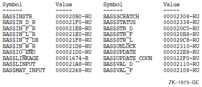
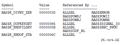
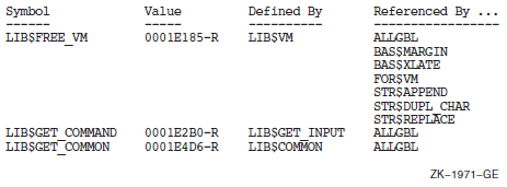
KEY1 is the first field in the line. It contains a symbol name.
KEY2 is the second field in the line. It contains a set of flags (for example, –R) providing information about the symbol.
VAL1 is the third field in the line. It contains the value of the symbol.
VAL2 is the fourth field in the line. It contains a set of flags describing VAL1.
REF1 and REF2 fields. Within each REF1 and REF2 pair, REF1 provides a set of flags and REF2 provides the name of a module that references the symbol.
Figure 9.5, ''Output Line for LIB$CRF_OUTPUT'' shows that any of these fields can be omitted from the output.
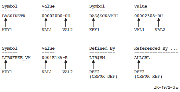
9.6. Example
The VAX Linker uses the cross-reference routines to generate cross-reference listings. This section uses the linker's code as an example of using the cross-reference routines in a MACRO program.
9.6.1. Defining Control Tables
The symbol-by-name table
The symbol-by-value table
LNK$NAMTAB:
            $CRFCTLTABLE   KEYTYPE=ASCIC,ERROR=LNK$ERR_RTN,_
                           OUTPUT=LNK$MAPOUT,KEY1TABLE=LNK$KEY1,_
                           KEY2TABLE=LNK$KEY2,VAL1TABLE=LNK$VAL1,_
                           VAL2TABLE=LNK$VAL2,REF1TABLE=LNK$REF1,_
                           REF2TABLE=LNK$REF2
|
LNK$NAMTAB |
Names the address of the control table |
|
KEYTYPE=ASCIC |
Specifies that the keys are counted ASCII strings (that is, symbol names) |
|
ERROR=LNK$ERR_RTN |
Indicates that LNK$ERR_RTN is the address of the routine to be executed in case of error |
|
OUTPUT=LNK$MAPOUT |
Names LNK$MAPOUT as the address of the user-supplied routine that prints the formatted table |
The remaining arguments provide the addresses of the field descriptor tables.
After setting up the control tables, the linker defines each field of the cross-reference output line, using the $CRFFIELD macro. After each set of definitions for a field, it calls $CRFFIELDEND to mark the end of the field.
The definition of LNK$VAL2 describes a flag to be associated with VAL1. The definition contains alternative bit patterns, depending on the bit mask. When an entry is made to the table, the entry contains flag information. Then, when LIB$CRF_OUTPUT is called to format the data, the routine checks each entry, matching the flags argument against the bit masks specified in the control table. When LIB$CRF_OUTPUT finds a match, it uses that definition to determine the format of the entry in the output table. For example, BIT_MASK=SYM$M_DEF marks an entry as the defining reference. The corresponding VAL1 entry is placed in the output table with an asterisk in its flags field.
The FAO control strings are defined to produce an output of the maximum character size for each field. This ensures that the columns will line up correctly in the output. For example, !15AC produces the variable symbol name left-aligned and right-filled with spaces. Another example is the three sets of characters to be printed for field VAL2. Each FAO control string produces two characters, which is the maximum size of the field.
LNK$KEY1:
            $CRFFIELD      BIT_MASK=0, FAO_STRING=\!15AC\,-
                           SET_CLEAR=SET,FIELD_WIDTH=15
            $CRFFIELDEND
LNK$KEY2:
            $CRFFIELD      BIT_MASK=0,FAO_STRING=\ \,-
                           SET_CLEAR=SET, FIELD_WIDTH=1
            $CRFFIELDEND

LNK$VAL1:
            $CRFFIELD      BIT_MASK=0,FAO_STRING=\!XL\,-
                           SET_CLEAR=SET,FIELD_WIDTH=8
            $CRFFIELDEND
LNK$VAL2:
            $CRFFIELD      BIT_MASK=0, FAO_STRING=\!2*  \,-
                           SET_CLEAR=SET,FIELD_WIDTH=2
            $CRFFIELD      BIT_MASK=SYM$M_REL,FAO_STRING=\-R\,-
                           SET_CLEAR=SET,FIELD_WIDTH=2
            $CRFFIELD      BIT_MASK=SYM$M_DEF, FAO_STRING=\-*\,-
                           SET_CLEAR=CLEAR,FIELD_WIDTH=2
            $CRFFIELDEND
LNK$REF1:
            $CRFFIELD      BIT_MASK=0,FAO_STRING=\!6* \,-
                           SET_CLEAR=SET,FIELD_WIDTH=6
            $CRFFIELD      BIT_MASK=SYM$M_WEAK,FAO_STRING=\!3* WK-\,-
                           SET_CLEAR=SET,FIELD_WIDTH=6
            $CRFFIELDEND

LNK$REF2:
            $CRFFIELD      BIT_MASK=0,FAO_STRING=\!16AC\,-
                           SET_CLEAR=SET,FIELD_WIDTH=16
            $CRFFIELDEND
LNK$VALTAB:
            $CRFCTLTABLE    KEYTYPE=BIN_U32, ERROR=LNK$ERR_RTN,-
                            OUTPUT=LNK$MAPOUT,KEY1TABLE=LNK$VAL1,-
                            KEY2TABLE=LNK$VAL2,VAL1TABLE=0,-
                            VAL2TABLE=0,REF1TABLE=LNK$REF1,-
                            REF2TABLE=LNK$REF2
9.6.2. Inserting Table Information
After initializing the format data for the symbol tables, the linker enters data into the cross-reference tables by calling LIB$CRF_INS_KEY.
        PUSHAB    VALUE_FLAGS
        PUSHAB    VALUE_ADDR
        PUSHAB    SYMBOL_ADDR
        PUSHAB    LNK$NAMTAB
CALLS #4,G^LIB$CRF_INS_KEY|
LNK$NAMTAB |
Is the address of the control table |
|
SYMBOL_ADDR |
Is the address of the counted ASCII string $MAPFLG |
|
VALUE_ADDR |
Is the address of the symbol value |
|
VALUE_FLAGS |
Is the address of a word whose bits are used to select special characters to print beside the value |
DEF:    .LONG     CRF$K_DEF
        PUSHAB    DEF
        PUSHAB    REF_FLAGS
        PUSHAB    REF_ADDR
        PUSHAB    SYMBOL_ADDR
        PUSHAB    LNK$NAMTAB
        CALLS     #5,G^LIB$CRF_INS_REF
|
LNK$NAMTAB |
Is the address of the control table |
|
SYMBOL_ADDR |
Is the address of the counted string $MAPFLG |
|
REF_ADDR |
Is the address of the referrer's counted ASCII string |
|
REF_FLAGS |
Is the address of a word whose bits are used to select special characters to print beside the reference |
REF:      .LONG     CRF$K_REF
          PUSHAB    REF
          PUSHAB    REF_FLAGS
          PUSHAB    REF_ADDR
          PUSHAB    SYMBOL_ADDR
          PUSHAB    LNK$NAMTAB
          CALLS     #5,G^LIB$CRF_INS_REF
The arguments are similar to the previous example, except for CRF$K_REF, which indicates that this is not the defining reference.
        PUSHAB    REF
        PUSHAB    REF_FLAGS
        PUSHAB    REF_ADDR
        PUSHAB    VAL_ADDR
        PUSHAB    LNK$VALTAB
CALLS #5,G^LIB$CRF_INS_REF|
LNK$VALTAB |
Is the address of the control table for the symbol synopsis by value |
|
VAL_ADDR |
Is the address of the value (binary longword key) |
|
REF_ADDR |
Is the address of the symbol name having the value contained in VAL_ADDR |
|
REF_FLAGS |
Is the address of a word whose bits are used to select special characters to print beside the value |
|
CRF$K_REF |
Is the indicator that this is not a defining reference |
9.6.3. Formatting Information for Output
LNWID:  .LONG   132
LNSP1:  .LONG   LINES_PAGE1
LNSOP:  .LONG   LINES_OTHR_PAGE
SAVE:   .LONG   CRF$K_SAVE
VAL:    .LONG   CRF$K_VALUES
        PUSHAB  VAL
        PUSHAB  SAVE
        PUSHAB  LNSOP
        PUSHAB  LNSP1
        PUSHAB  LNWID
        PUSHAB  LNK$NAMTAB
        CALLS   #6,G^LIB$CRF_OUTPUT
In this example, CRF$K_VALUES means that no reference indicators are to be printed, while CRF$K_SAVE means that the cross-reference table is to be saved. It is also possible to list all cross-reference data. The type of output produced by this call is shown in Section 9.5, ''Cross-Reference Output'', Figure 9.2, ''Summary of Symbol Names and Values''.
LNWID:  .LONG   132
LNSP1:  .LONG   LINES_PAGE1
LNSOP:  .LONG   LINES_OTHR_PAGE
DELETE: .LONG   CRF$K_DELETE
DEFREF: .LONG   CRF$K_DEF_REF
        PUSHAB  DELETE
        PUSHAB  DEFREF
        PUSHAB  LNSOP
        PUSHAB  LNSP1
        PUSHAB  LNWID
        PUSHAB  LNK$NAMTAB
        CALLS   #6,G^LIB$CRF_OUTPUT
The type of output produced by this call is shown in Section 9.5, ''Cross-Reference Output'', Figure 9.4, ''Summary Indicating Defining Module''.
CRF$K_DEFS_REFS indicates that the first two reference fields are used for the defining references, and CRF$K_DELETE indicates that the table is deleted.
LNWID:      .LONG     132
LNSP1:      .LONG     LINES_PAGE1
LNSOP:      .LONG     LINES_OTHR_PAGE
VALREF:     .LONG     CRF$K_VALS_REF
DELETE:     .LONG     CRF$K_DELETE
            PUSHAB    DELETE
            PUSHAB    VALREF
            PUSHAB    LNSOP
            PUSHAB    LNSP1
            PUSHAB    LNWID
            PUSHAB    LNK$VALTAB
            CALLS     #6,G^LIB$CRF_OUTPUT
This is similar to the previous call in that it produces a complete cross-reference output by value, but it does not have the defining reference fields.
9.7. How to Link to the Cross-Reference Shareable Image
SYS$LIBRARY:IMAGELIB/INCLUDE=CRFSHRChapter 10. Shareable Resources
This chapter describes the techniques available for sharing data and program code among programs.
DCL symbols and logical names
Libraries
Shareable images
Global sections
Common blocks installed in a shareable image
OpenVMS Record Management Services (RMS) shared files
Symbols and logical names are also used for intraprocess and interprocess communication; therefore, they are discussed in Chapter 18, "Logical Name and Logical Name Tables".
Libraries and shareable images are used for sharing program code.
Global sections, common blocks stored in shareable images, and RMS shared files are used for sharing data. You can also use common blocks for interprocess communication. For more information, refer to VSI OpenVMS Programming Concepts Manual, Volume I.
10.1. Sharing Program Code
Text, macro, or object libraries that store sections of code. Text and macro libraries store source code; object libraries store object code. You can create and manage libraries using the Librarian utility (LIBRARIAN). Refer to the VSI OpenVMS Command Definition, Librarian, and Message Utilities Manual for complete information about using the Librarian utility.
Shareable images are images that can be linked with executable images. These images can also be stored in libraries.
10.1.1. Object Libraries
You can use object libraries to store frequently used routines, thereby avoiding repeated recompiling, which allows you to minimize the number of files you must maintain, and simplify the linking process. The source code for the object modules can be in any supported language, and the object modules can be linked with any other modules written in any supported language.
Use the .OLB file extension for any object library. All modules stored in an object library must have the file extension .OBJ.
10.1.1.1. System- and User-Defined Default Object Libraries
The operating system provides a default system object library, STARLET.OLB. You can also define one or more default object libraries to be automatically searched before the system object library. The logical names for the default object libraries are LNK$LIBRARY and LNK$LIBRARY_1 through LNK$LIBRARY_999. To use one of these default libraries, first define the logical name. The libraries are searched sequentially starting at LNK$LIBRARY. Do not skip any numbers. If you store object modules in the default libraries, you do not have to specify the mat link time. However, you do have to maintain and manage them as you would any library.
$ DEFINE LNK$LIBRARY $DISK1:[DEV]PROCEDURES
10.1.1.2. How the Linker Searches Libraries
When the linker is resolving global symbol references, it searches user default libraries at the process level first, then libraries at the group and system level. Within levels, the library defined as LNK$LIBRARY is searched first, then LNK$LIBRARY_1, LNK$LIBRARY_2, and so on.
10.1.1.3. Creating an Object Library
$ LIBRARY/CREATE INCOME
10.1.1.4. Managing an Object Library
$ LIBRARY/REPLACE INCOME GETSTATS
$ DELETE GETSTATS.OBJ;*
$ LIBRARY/LIST/ONLY=GET* INCOME
Use the /DELETE qualifier to delete a library module and the /EXTRACT qualifier to recreate an object file. If you delete many modules, you should also compress (/COMPRESS qualifier) and purge (PURGE command) the library. Note that the /ONLY, /DELETE, and /EXTRACT qualifiers require the names of modules—not file names—and that the names are specified as qualifier values, not parameter values.
10.1.2. Text and Macro Libraries
Any frequently used routine can be stored in libraries as source code. Then, when you need the routine, it can be called in from your source program.
Source code modules are stored in text libraries. The file extension fora text library is .TLB.
When using VAX MACRO assembly language, any source code module can be stored in a macro library. The file extension for a macro library is .MLB. Any source code module stored in a macro library must have the file extension .MAR.
You also use LIBRARIAN to create and manage text and macro libraries. Refer to Section 10.1.1.3, ''Creating an Object Library'' and Section 10.1.1.4, ''Managing an Object Library'' for a summary of LIBRARIAN commands.
10.2. Shareable Images
Saves disk space—The executable images to which the shareable image is linked do not physically include the shareable image. Only one copy of the shareable image exists.
Simplifies maintenance—If you use transfer vectors and the GSMATCH (on VAX systems) or symbol vectors (on Alpha and IA-64 systems) option, you can modify, recompile, and relink a shareable image without having to relink any executable image that is linked with it.
Shareable images can also save memory, provided that they are installed as shared images. See the VSI OpenVMS Linker Utility Manual for more information about creating shareable images and shareable image libraries.
10.3. Symbols
Symbols are names that represent locations (addresses) in virtual memory. More precisely, a symbol's value is the address of the first, or low-order, byte of a defined area of virtual memory, while the characteristics of the defined are a provide the number of bytes referred to. For example, if you define TOTAL_HOUSES as an integer, the symbol TOTAL_HOUSES is assigned the address of the low-order byte of a 4-byte area in virtual memory. Some system components (for example, the debugger) permit you to refer to areas of virtual memory by their actual addresses, but symbolic references are always recommended.
10.3.1. Defining Symbols
A symbolic name can consist of letters, digits, underscores (_), and dollar signs ($). Uppercase and lowercase letters are equivalent. By convention, dollar signs are restricted to symbols used in system components. (If you do not use the dollar sign in your symbolic names, you will never accidentally duplicate a system-defined symbol).
10.3.2. Local and Global Symbols
Symbols are either local or global in scope. A local symbol can only be referenced within the program unit in which it is defined. Local symbol names must be unique among all other local symbols within the program unit but not within other program units in the program. References to local symbols are resolved at compile time.
A global symbol can be referenced outside the program unit in which it is defined. Global symbol names must be unique among all other global symbols within the program. References to global symbols are not resolved until link time.
References to global symbols in the executable portion of a program unit are usually invocations of subprograms. If you reference a global symbol in any other capacity (as an argument or data value—see the following paragraph), you must define the symbol as external or intrinsic in the definition portion of the program unit.
System facilities, such as the Message utility and the VAX MACRO assembler, use global symbols to define data values.
CHARACTER*255   NEW_TEXT
INTEGER         STATUS
INTEGER*2       NT_SIZ
INTEGER         LIB$GET_INPUT
EXTERNAL        RMS$_EOF
STATUS = LIB$GET_INPUT (NEW_TEXT,
2                       'New text: ',
2                       NT_SIZ)
IF ((.NOT. STATUS) .AND.
2   (STATUS .NE. %LOC (RMS$_EOF))) THEN
  CALL LIB$SIGNAL (RETURN_STATUS BY VALUE)
END IF
10.3.3. Resolving Global Symbols
Explicitly named modules and libraries – Generally used to resolve user-defined global symbols, such as subprogram names and condition codes. These modules and libraries are searched in the order in which they are specified.
System default libraries – Generally used to resolve system-defined global symbols, such as procedure names and condition codes.
User default libraries – Generally used to avoid explicitly naming libraries, thereby simplifying linking.
If the linker cannot find the symbol, the symbol is said to be unresolved and a warning results. You can run an image containing unresolved symbols. The image runs successfully as long as it does not access any unresolved symbol. For example, if your code calls a subroutine but the subroutine call is not executed, the image runs successfully.
If an image accesses an unresolved global symbol, results are unpredictable. Usually the image fails with an access violation (attempting to access a physical memory location outside those assigned to the program's virtual memory addresses).
10.3.3.1. Explicitly Named Modules and Libraries
$ LINK INCOME, GETSTATS
$ LINK INCOME,INCOME/LIBRARY
10.3.3.2. System Default Libraries
Link operations automatically check the system object and shareable image libraries for any references to global symbols not resolved by your explicitly named object modules and libraries. The system object and shareable image libraries include the entry points for the RTL routines and system services, condition codes, and other system-defined values. Invocations of these modules do not require any explicit action by you at link time.
10.3.3.3. User Default Libraries
If you write general-purpose procedures or define general-purpose symbols, you can place them in a user default library. (You can also make your development library a user default library.) In this way, you can link to the modules containing these procedures and symbols without explicitly naming the library in the DCL LINK command. To name a single-user library, equate the file name of the library to the logical name LNK$LIBRARY. For subsequent default libraries, use the logical names LNK$LIBRARY_1 through LNK$LIBRARY_999, as described in Section 10.1.1, ''Object Libraries''.
10.3.3.4. Making a Library Available for Systemwide Use
$ DEFINE/SYSTEM LNK$LIBRARY $DISK1:[DEV]PROCEDURES
10.3.3.5. Macro Libraries
 .TITLE macro-name
 macro-name      GLOBAL
   .
   .
   .
 .END
The following example is a macro program that includes two system macros:
LBRDEF.MAR
 .TITLE $LBRDEF
 $LBRDEF GLOBAL
 $LHIDEF GLOBAL
 .END
$ MACRO LBRDEF
$ LIBRARY/REPLACE INCOME LBRDEF
$ DELETE LBRDEF.OBJ;*
$ LINK INCOME,INCOME/LIBRARY
$ LINK INCOME,LBRDEF,INCOME/LIBRARY
10.3.4. Sharing Data
Typically, you use an installed common block either to facilitate interprocess communication or to allow two or more processes to access the same data simultaneously. However, you must have the CMKRNL privilege to install the common block. If you do not have the CMKRNL privilege, global sections allow you to perform the same operations.
10.3.4.1. Installed Common Blocks
To share data among processes by using a common block, you must install the common block as a shared shareable image and link each program that references the common block against that shareable image.
Define a common block—Write a program that declares the variables in the common block and defines the common block. This program should not contain executable code. The following VSI Fortran program defines a common block:
INC_COMMON.FOR
INTEGER TOTAL_HOUSES
REAL PERSONS_HOUSE (2048),
2    ADULTS_HOUSE (2048),
2    INCOME_HOUSE (2048)
COMMON /INCOME_DATA/ TOTAL_HOUSES,
2                    PERSONS_HOUSE,
2                    ADULTS_HOUSE,
2                    INCOME_HOUSE

END
- Create the shareable image—Compile the program containing the common block. Use the LINK/SHAREABLE command to create a shareable image containing the common block.
$ FORTRAN INC_COMMON
$ LINK/SHAREABLE INC_COMMON
For Alpha only, you need to specify a Linker options file (shown here as SYS$INPUT to allow typed input) to specify the PSECT attributes of the COMMON block PSECT and include it in the global symbol table:$ LINK/SHAREABLE INC_COMMON ,SYS$INPUT/OPTION _ SYMBOL_VECTOR=(WORK_AREA=PSECT) _ PSECT_ATTR=WORK_AREA,SHRWith VSI Fortran 90 on OpenVMS Alpha systems, the default PSECT attribute for a common block is NOSHR. To use a shared installed common block, you must specify one of the following:The SHR attribute in a cDEC$ PSECT directive in the source file
The SHR attribute in the PSECT_ATTR option in the Linker options file. The shareable image must be installed.
If the !DEC$ PSECT (same as cDEC$ PSECT) directive specified the SHR attribute, the LINK command is as follows:$ LINK/SHAREABLE INC_COMMON ,SYS$INPUT/OPTION _ SYMBOL_VECTOR=(WORK_AREA=PSECT)
Copy the shareable image. Once created, you should copy the shareable image into SYS$SHARE before it is installed. The file protection of the .EXE file must allow write access for the processes running programs that will access the shareable image (shown for Group access in the following COPY command):$ COPY/LOG DISK$:[INCOME.DEV]INC_COMMON.EXE SYS$SHARE:*.* _ /PROTECTION=G:RWE
If you do not copy the installed shareable image to SYS$SHARE, before running executable images that reference the installed shareable common image, you must define a logical name that specifies the location of that image.
On Alpha and IA-64 systems, when compiling the program that contains the common block declarations, consistently use the same /ALIGNMENT and /GRANULARITY qualifiers used to compile the common block data declaration program that has been installed as a shareable image. For more information, see Section 10.3.4.3, ''Synchronizing Access to Global Sections''.
Install the shareable image—Use the DCL command SET PROCESS/PRIVILEGE to give yourself CMKRNL privilege (required for use of the Install utility). Use the DCL command INSTALL to invoke the interactive Install utility. When the INSTALL prompt appears, enter CREATE, followed by the complete file specification of the shareable image that contains the common block (the file type defaults to .EXE) and the qualifiers /WRITEABLE and /SHARED. The Install utility installs your shareable image and reissues the INSTALL prompt. Enter EXIT to exit. Remember to remove CMKRNL privilege. (For complete documentation of the Install utility, see the VSI OpenVMS System Management Utilities Reference Manual).
The following example shows how to install a shareable image:$ SET PROCESS/PRIVILEGE=CMKRNL $ INSTALL INSTALL> CREATE DISK$USER:[INCOME.DEV]INC_COMMON - _INSTALL> /WRITEABLE/SHARED INSTALL> EXIT $ SET PROCESS/PRIVILEGE=NOCMKRNLNote
A disk containing an installed image cannot be dismounted. To remove an installed image, invoke the Install utility and enter DELETE followed by the complete file specification of the image. The DELETE subcommand does not delete the file from the disk; it removes the file from the list of known installed images.
Include the same variable and common block definitions in the program.
Compile the program.
For Alpha and I64, when compiling the program that contains the common block declarations, consistently use the same /ALIGNMENT and /GRANULARITY qualifiers used to compile the common block data declaration program that has been installed as a shareable image. For more information, see Section 10.3.4.3, ''Synchronizing Access to Global Sections''.
- Link the program against the shareable image that contains the common block. (Linking against a shareable image requires an options file).
$ LINK INCOME, DATA/OPTION
$ LINK REPORT, DATA/OPTION
DATA.OPT
INC_COMMON/SHAREABLE
For Alpha only, linking is as follows:INC_COMMON/SHAREABLE PSECT_ATTR=WORK_AREA, SHR
If a !DEC$ PSECT (cDEC$ PSECT) directive specified the SHR PSECT attribute, the linker options file INCOME.OPT would contain the following line:INC_COMMON/SHAREABLE
The source line containing the !DEC$ PSECT directive would be as follows:!DEC$ PSECT /INC_COMMON/ SHR Execute the program.
If the installed image is not located in SYS$SHARE, you must define a logical name that specifies the location of that image. The logical name (in this example INC_COMMON) is the name of the installed base.
In the previous series of examples, the two programs INCOME and REPORT access the same area of memory through the installed common block INCOME_DATA (defined in INC_COMMON.FOR).
Typically, programs that access shared data use common event flag clusters to synchronize read and write access to the data. Refer to VSI OpenVMS Programming Concepts Manual, Volume I, for more information about using event flags for program synchronization.
10.3.4.2. Using Global Sections
To share data by using global sections, each process that plans to access the data includes a common block of the same name, which contains the variables for the data. The first process to reference the data declares the common block as a global section and, optionally, maps data to the section. (Data in global sections, as in private sections, must be page aligned).
Additional argument—Specify the name of the global section (argument 5).A program uses this name to access a global section.
Additional flag—Set the SEC$V_GBL bit of the
flagsargument to indicate that the section is a global section.
As other programs need to reference the data, each can use either SYS$CRMPSC or SYS$MGBLSC to map data into the global section. If you know that the global section exists, the best practice is to use the SYS$MGBLSC system service.
SYS$MGBLSC (inadr ,[retadr] ,[acmode] ,[flags] ,gsdnam ,[ident] ,[relpag])Refer to the VSI OpenVMS System Services Reference Manual for complete information about this system service.
!UFO_CREATE.FOR
   .
   .
   .
INTEGER FUNCTION UFO_CREATE (FAB,
2                            RAB,
2                            LUN)

! Include RMS definitions
INCLUDE '($FABDEF)'
INCLUDE '($RABDEF)'

! Declare dummy arguments
RECORD /FABDEF/ FAB
RECORD /RABDEF/ RAB
INTEGER LUN

! Declare channel
INTEGER*4 CHAN
COMMON /CHANNEL/ CHAN

! Declare status variable
INTEGER STATUS

! Declare system procedures
INTEGER SYS$CREATE

! Set useropen bit in the FAB options longword
FAB.FAB$L_FOP = FAB.FAB$L_FOP .OR. FAB$M_UFO
! Open file
STATUS = SYS$CREATE (FAB)

! Read channel from FAB status word
CHAN = FAB.FAB$L_STV

! Return status of open operation
UFO_CREATE = STATUS

END
DATA.OPT
PSECT_ATTR = DATA, PAGE
DEVICE.FOR
! Define global section flags
INCLUDE '($SECDEF)'
! Mask for section flags
INTEGER SEC_MASK
! Logical unit number for section file
INTEGER INFO_LUN
! Channel number for section file
INTEGER SEC_CHAN
COMMON /CHANNEL/ SEC_CHAN
! Length for the section file
INTEGER SEC_LEN
! Data for the section file
CHARACTER*12 DEVICE,
2            PROCESS
CHARACTER*6 TERMINAL
COMMON /DATA/ DEVICE,
2             PROCESS,
2             TERMINAL
! Location of data
INTEGER PASS_ADDR (2),
2       RET_ADDR (2)
! Two common event flags
INTEGER REQUEST_FLAG,
2       INFO_FLAG
DATA REQUEST_FLAG /70/
DATA INFO_FLAG /71/
! User-open routines
INTEGER UFO_CREATE
EXTERNAL UFO_CREATE
   .
   .
   .
! Open the section file
STATUS = LIB$GET_LUN (INFO_LUN)
IF (.NOT. STATUS) CALL LIB$SIGNAL(%VAL(STATUS))
SEC_MASK = SEC$M_WRT .OR. SEC$M_DZRO .OR. SEC$M_GBL
! (last address -- first address + length of last element + 511)/512
SEC_LEN = ( (%LOC(TERMINAL) - %LOC(DEVICE) + 6 + 511)/512 )
OPEN (UNIT=INFO_LUN,
2     FILE='INFO.TMP',
2     STATUS='NEW',
2     INITIALSIZE = SEC_LEN,
2     USEROPEN = UFO_CREATE)
! Free logical unit number and map section
CLOSE (INFO_LUN)
! Get location of data
PASS_ADDR (1) = %LOC (DEVICE)
PASS_ADDR (2) = %LOC (TERMINAL)
STATUS = SYS$CRMPSC (PASS_ADDR,      ! Address of section
2                    RET_ADDR,       ! Addresses mapped
2                    ,
2                    %VAL(SEC_MASK), ! Section mask
2                    'GLOBAL_SEC',   ! Section name
2                    ,,
2                    %VAL(SEC_CHAN), ! I/O channel
2                    ,,,)
IF (.NOT. STATUS) CALL LIB$SIGNAL(%VAL(STATUS))
! Create the subprocess
STATUS = SYS$CREPRC (,
2                    'GETDEVINF',    ! Image
2                    ,,,,,
2                    'GET_DEVICE',   ! Process name
2                    %VAL(4),,,)     ! Priority
IF (.NOT. STATUS) CALL LIB$SIGNAL(%VAL(STATUS))
! Write data to section
DEVICE = '$FLOPPY1'
! Get common event flag cluster and set flag
STATUS = SYS$ASCEFC (%VAL(REQUEST_FLAG),
2                    'CLUSTER',,)
IF (.NOT. STATUS) CALL LIB$SIGNAL(%VAL(STATUS))
STATUS = SYS$SETEF (%VAL(REQUEST_FLAG))
IF (.NOT. STATUS) CALL LIB$SIGNAL(%VAL(STATUS))
! When GETDEVINF has the information, INFO_FLAG is set
STATUS = SYS$WAITFR (%VAL(INFO_FLAG))
IF (.NOT. STATUS) CALL LIB$SIGNAL(%VAL(STATUS))
   .
   .
   .
GETDEVINF.FOR
! Define section flags
INCLUDE '($SECDEF)'
! Mask for section flags
INTEGER SEC_MASK
! Data for the section file
CHARACTER*12 DEVICE,
2            PROCESS
CHARACTER*6  TERMINAL
COMMON /DATA/ DEVICE,
2             PROCESS,
2             TERMINAL
! Location of data
INTEGER PASS_ADDR (2),
2       RET_ADDR (2)
! Two common event flags
INTEGER REQUEST_FLAG,
2       INFO_FLAG
DATA REQUEST_FLAG /70/
DATA INFO_FLAG /71/
   .
   .
   .
! Get common event flag cluster and wait
! for GBL1.FOR to set REQUEST_FLAG
STATUS = SYS$ASCEFC (%VAL(REQUEST_FLAG),
2                    'CLUSTER',,)
IF (.NOT. STATUS) CALL LIB$SIGNAL (%VAL(STATUS))
STATUS = SYS$WAITFR (%VAL(REQUEST_FLAG))
IF (.NOT. STATUS) CALL LIB$SIGNAL (%VAL(STATUS))
! Get location of data
PASS_ADDR (1) = %LOC (DEVICE)
PASS_ADDR (2) = %LOC (TERMINAL)
! Set write flag
SEC_MASK = SEC$M_WRT
! Map the section
STATUS = SYS$MGBLSC (PASS_ADDR,      ! Address of section
2                    RET_ADDR,       ! Address mapped
2                    ,
2                    %VAL(SEC_MASK), ! Section mask
2                    'GLOBAL_SEC',,) ! Section name
IF (.NOT. STATUS) CALL LIB$SIGNAL (%VAL(STATUS))
! Call GETDVI to get the process ID of the
! process that allocated the device, then
! call GETJPI to get the process name and terminal
! name associated with that process ID.
! Set PROCESS equal to the process name and
! set TERMINAL equal to the terminal name.
   .
   .
   .
! After information is in GLOBAL_SEC
STATUS = SYS$SETEF (%VAL(INFO_FLAG))
IF (.NOT. STATUS) CALL LIB$SIGNAL (%VAL(STATUS))

END
By default, a global section is deleted when no image is mapped to it. Such
global sections are called temporary global sections. If you have the PRMGBL
privilege, you can create a permanent global section (set the
SEC$V_PERM bit of the flags
argument when you invoke SYS$CRMPSC). A permanent
global section is not deleted until after it is marked for deletion with the
SYS$DGBLSC system service (requires PRMGBL). Once a
permanent section is marked for deletion, it is like a temporary section; when
no image is mapped to it, the section is deleted.
10.3.4.3. Synchronizing Access to Global Sections
On Alpha and IA-64 systems, if more than one process or thread will write to a shared global section containing COMMON block data, the user program may need to synchronize access to COMMON block variables.
$ F90 /ALIGN=COMMONS=NATURAL /GRANULARITY=LONGWORD INC_COMMON
On Alpha and IA-64 systems, using /GRANULARITY=LONGWORD for 4-byte variables or /GRANULARITY=QUADWORD for 8-byte variables ensures that adjacent data is not accidentally effected. To ensure access to 1-byte variables, specify /GRANULARITY=BYTE.
On Alpha systems, accessing data items less than four bytes slows run-time performance. In this case you might want to consider synchronizing read and write access to the data on the same node.
One way for programs accessing shared data is to use common event flag clusters to synchronize read and write access to the data on the same node. In the simplest case, one event flag in a common event flag cluster might indicate that a program is writing data, and a second event flag in the cluster might indicate that a program is reading data. Before accessing the shared data, a program must examine the common event flag cluster to ensure that accessing the data does not conflict with an operation already in progress.
The lock manager system services (SYS$ENQ and SYS$DEQ)
The hibernate and wake system services (SYS$HIBER and SYS$WAKE)
You could also use Assembler code for synchronization.
10.3.4.4. RMS Shared Files
Indexed files
Relative files
Sequential files with 512-byte fixed-length records
To coordinate access to a file, RMS uses the lock manager. You can override the RMS lock manager by controlling access yourself. Refer to VSI OpenVMS Programming Concepts Manual, Volume I, for more information about synchronizing access to resources.
Chapter 11. System Time Operations
This chapter describes the types of system time operations performed by the operating system.
11.1. System Time Format
An absolute time that is a specific date or time of day, or both. Absolute times are always positive values (or 0).
A delta time that is an offset from the current time to a time or date in the future. Delta times are always expressed as negative values and cannot be zero. The binary format number for delta time will always be negative.
If you specify 0 as the address of a time value, the operating system supplies the current date and time.
11.1.1. Absolute Time Format
dd-MMM-yyyy hh:mm:ss.cc
|
dd |
Day of the month (2 characters) |
|
MMM |
Month (first 3 characters of the month in uppercase) |
|
yyyy |
Year (4 characters) |
|
hh |
Hours of the day in 24-hour format (2 characters) |
|
mm |
Minutes (2 characters) |
|
ss.cc |
Seconds and hundredths of a second (5 characters) |
11.1.2. Delta Time Format
dddd hh:mm:ss.cc
|
dddd |
Day of the month (4 characters) |
|
hh |
Hour of the day (2 characters) |
|
mm |
Minutes (2 characters) |
|
ss.cc |
Seconds and hundredths of a second (5 characters) |
A delta time is maintained as an integer value representing an amount of time in 100-ns units.
11.2. Time Conversion and Date/Time Manipulation
This section presents information about time conversion and date/time manipulation features, and the routines available to implement them.
11.2.1. Time Conversion Routines
Obtain the current date and time in an ASCII string or in system format
Convert an ASCII string into the system time format
Convert a system time value into an ASCII string
Convert the time from system format to integer values
|
Routine |
Function |
|---|---|
|
Time Conversion Run-Time Library (LIB$) Routines | |
|
LIB$CONVERT_DATE_STRING |
Converts an input date/time string to an operating system internal time. |
|
LIB$CVT_FROM_INTERNAL_TIME |
Converts an operating system standard internal binary time value to an external integer value. The value is converted according to a selected unit of time operation. |
|
LIB$CVTF_FROM_INTERNAL_TIME |
Converts an operating system standard internal binary time to an external F-floating point value. The value is converted according to a selected unit of time operation. |
|
LIB$CVT_TO_INTERNAL_TIME |
Converts an external integer time value to an operating system standard internal binary time value. The value is converted according to a selected unit of time operation. |
|
LIB$CVTF_TO_INTERNAL_TIME |
Converts an F-floating-point time value to an internal binary time value. |
|
LIB$CVT_VECTIM |
Converts a seven-word array (as returned by the SYS$NUMTIM system service) to an operating system standard format internal time. |
|
LIB$FORMAT_DATE_TIME |
Allows you to select at run time a specific output language and format for a date or time, or both. |
|
LIB$SYS_ASCTIM |
Provides a simplified interface between higher-level languages and the $ASCTIM system service. |
|
Time Conversion System Service Routines | |
|
SYS$ASCTIM |
Converts an absolute or delta time from 64-bit binary time format to an ASCII string. |
|
SYS$ASCUTC |
Converts an absolute time from 128-bit Coordinated Universal Time (UTC) format to an ASCII string. |
|
SYS$BINTIM |
Converts an ASCII string to an absolute or delta time value in a binary time format. |
|
SYS$BINUTC |
Converts an ASCII string to an absolute time value in the 128-bit UTC format. |
|
SYS$FAO |
Converts a binary value into an ASCII character string in decimal, hexadecimal, or octal notation and returns the character string in an output string. |
|
SYS$GETUTC |
Returns the current time in 128-bit UTC format. |
|
SYS$NUMTIM |
Converts an absolute or delta time from 64-bit system time format to binary integer date and time values. |
|
SYS$NUMUTC |
Converts an absolute 128-bit binary time into its numeric components. The numeric components are returned in local time. |
|
SYS$TIMCON |
Converts 128-bit UTC to 64-bit system format or 64-bit system format to 128-bit UTC based on the value of the convert flag. |
You can use the SYS$GETTIM system service to get the current time in internal format, or you can use SYS$BINTIM to convert a formatted time to an internal time, as shown in Section 11.3.2, ''Obtaining Current Time and Date with SYS$GETTIM''. You can also use the LIB$DATE_TIME routine to obtain the time, LIB$CVT_FROM_INTERNAL_TIME to convert an internal time to an external time, and LIB$CVT_TO_INTERNAL to convert from an external time to an internal time.
11.2.1.1. Calculating and Displaying Time with SYS$GETTIM and LIB$SUBX
   .
   .
   .
! Internal times
! Input time in absolute format, dd-mmm-yyyy hh:mm:ss.ss
!
INTEGER*4 CURRENT_TIME (2),
2         PAST_TIME (2),
2         TIME_DIFFERENCE (2),
2         ZERO (2)
DATA ZERO /0,0/
! Formatted times
CHARACTER*23 PAST_TIME_F
CHARACTER*16 TIME_DIFFERENCE_F
! Status
INTEGER*4 STATUS
! Integer functions
INTEGER*4 SYS$GETTIM,
2         LIB$GET_INPUT,
2         SYS$BINTIM,
2         LIB$SUBX,
2         SYS$ASCTIM
! Get current time
STATUS = SYS$GETTIM (CURRENT_TIME)
IF (.NOT. STATUS) CALL LIB$SIGNAL (%VAL (STATUS))
! Get past time and convert to internal format
STATUS = LIB$GET_INPUT (PAST_TIME_F,
2                       'Past time (in absolute format): ')
IF (.NOT. STATUS) CALL LIB$SIGNAL (%VAL (STATUS))
STATUS = SYS$BINTIM (PAST_TIME_F,
2                    PAST_TIME)
IF (.NOT. STATUS) CALL LIB$SIGNAL (%VAL (STATUS))
! Subtract past time from current time
STATUS = LIB$SUBX (CURRENT_TIME,
2                  PAST_TIME,
2                  TIME_DIFFERENCE)
IF (.NOT. STATUS) CALL LIB$SIGNAL (%VAL (STATUS))
! If resultant time is in absolute format (positive value means
! most significant bit is not set), convert it to delta time
IF (.NOT. (BTEST (TIME_DIFFERENCE(2),31))) THEN
  STATUS = LIB$SUBX (ZERO,
2                    TIME_DIFFERENCE,
2                    TIME_DIFFERENCE)
END IF
! Format time difference and display
STATUS = SYS$ASCTIM (, TIME_DIFFERENCE_F,
2                    TIME_DIFFERENCE,)
IF (.NOT. STATUS) CALL LIB$SIGNAL (%VAL (STATUS))
TYPE *, 'Time difference = ', TIME_DIFFERENCE_F
END
If you are ignoring the time portion of date/time (that is, working just at the date level), the LIB$DAY routine might simplify your calculations. LIB$DAY returns to you the number of days from the base system date to a given date.
11.2.1.2. Obtaining Absolute Time with SYS$ASCTIM and SYS$BINTIM
The Convert Binary Time to ASCII String (SYS$ASCTIM) system service is the converse of the Convert ASCII String to Binary Time (SYS$BINTIM) system service. You provide the service with the time in the ASCII format shown in Section 11.3.2, ''Obtaining Current Time and Date with SYS$GETTIM''. The service then converts the string to a time value in 64-bit format. You can use this returned value as input to a timer scheduling service.
#include <stdio.h>
#include <descrip.h>

/* Buffer to receive binary time */
struct {
        unsigned int buff1, buff2;
}binary_noon;

main()  {

        unsigned int status;
        $DESCRIPTOR(ascii_noon,"-- 12:00:00.00");  /* noon
                                                     (absolute time) */

/* Convert time */
        status = SYS$BINTIM(&ascii_noon,           /* timbuf - ASCII time */
                 &binary_noon);                    /* timadr - binary time */

}
When the SYS$BINTIM service completes, a 64-bit time value representing "noon today" is returned in the quadword at BINARY_NOON.
11.2.1.3. Obtaining Delta Time with SYS$BINTIM
dddd hh:mm:ss.cc
The first field, indicating the number of days, must be specified as 0 if you are specifying a delta time for the current day.
#include <stdio.h>
#include <descrip.h>

/* Buffer to receive binary time */
struct {
        unsigned int buff1, buff2;
}btenmin;

main()  {

        unsigned int status;
        $DESCRIPTOR(atenmin,"0 00:10:00.00");      /* 10-min delta */

/* Convert time from ASCII to binary */
        status = SYS$BINTIM(&atenmin,   /* timbuf - time in ASCII */
                &btenmin);              /* timadr - binary time   */

}1 second = 10 million * 100 ns
FIVESEC: .LONG -10*1000*1000*5,-1 ; Five seconds
The value 10 million is expressed as 10 *1000 *1000 for readability. Note that the delta time value is negative.
If you use this notation, however, you are limited to the maximum number of 100-ns units that can be expressed in a longword. In time values this is slightly more than 7 minutes.
11.2.1.4. Obtaining Numeric and ASCII Time with SYS$NUMTIM
The Convert Binary Time to Numeric Time (SYS$NUMTIM) system service converts a time in the system format into binary integer values. The service returns each of the components of the time (year, month, day, hour, and so on) into a separate word of a 7-word buffer. The SYS$NUMTIM system service and the format of the information returned are described in the VSI OpenVMS System Services Reference Manual.
You use the SYS$ASCTIM system service to format the time in ASCII for inclusion in an output string. The SYS$ASCTIM service accepts as an argument the address of a quadword that contains the time in system format and returns the date and time in ASCII format.
If you want to include the date and time in a character string that contains additional data, you can format the output string with the Formatted ASCII Output (SYS$FAO) system service. The SYS$FAO system service converts binary values to ASCII representations, and substitutes the results in character strings according to directives supplied in an input control string. Among these directives are !%T and !%D, which convert a quadword time value to an ASCII string and substitute the result in an output string. For examples of how to do this, see the discussion of $FAO in the VSI OpenVMS System Services Reference Manual.
11.2.2. Date/Time Manipulation Routines
The run-time LIB$ facility provides several date/time manipulation routines. These routines let you add, subtract, and multiply dates and times. Use the LIB$ADDX and LIB$SUBX routines to add and subtract times, since the times are defined in integer arrays. Use LIB$ADD_TIMES and LIB$SUB_TIMES to add and subtract two quadword times. When manipulating delta times, remember that they are stored as negative numbers. For example, to add a delta time to an absolute time, you must subtract the delta time from the absolute time. Use LIB$MULT_DELTA_TIME and LIB$MULTF_DELTA_TIME to multiply delta times by scalar and floating scalar.
|
Routine |
Function |
|---|---|
|
LIB$ADD_TIMES |
Adds two quadword times |
|
LIB$FORMAT_DATE_TIME |
Formats a date and/or time for output |
|
LIB$FREE_DATE_TIME_CONTEXT |
Frees the date/time context |
|
LIB$GET_MAXIMUM_DATE_LENGTH |
Returns the maximum possible length of an output date/time string |
|
LIB$GET_USERS_LANGUAGE |
Returns the user's selected language |
|
LIB$INIT_DATE_TIME_CONTEXT |
Initializes the date/time context with a user-specified format |
|
LIB$MULT_DELTA_TIME |
Multiplies a delta time value by an integer scalar value |
|
LIB$MULTF_DELTA_TIME |
Multiplies a delta time value by an F-floating point scalar value |
|
LIB$SUB_TIMES |
Subtracts two quadword times |
11.3. Timer Routines Used to Obtain and Set Current Time
This section presents information about obtaining the current date and time, and setting current time. The run-time library (LIB$) facility provides date/time utility routines for languages that do not have built-in time and date functions. These routines return information about the current date and time or a date/time specified by the user. You can obtain the current time by using the LIB$DATE_TIME routine or by implementing the SYS$GETTIM system service. To set the current time, use the SYS$SETTIME system service.
| Routine | Function |
|---|---|
|
Timer Run-Time Library (LIB$) Routines | |
|
LIB$DATE_TIME |
Returns, using a string descriptor, the operating system date and time in the semantics of a string that the user provides. |
|
LIB$DAY |
Returns the number of days since the system zero date of
November
17, 1858. This routine takes one required
argument and two optional arguments:
|
|
LIB$DAY_OF_WEEK |
Returns the numeric day of the week for an input time value. If the input time value is 0, the current day of the week is returned. The days are numbered 1 through 7: Monday is day 1 and Sunday is day 7. |
|
System Service Routine | |
|
SYS$SETIME |
Changes the value of or recalibrates the system time. |
11.3.1. Obtaining Current Time and Date with LIB$DATE_TIME
! Formatted date and time
CHARACTER*23 DATETIME
! Status and library procedures
INTEGER*4 STATUS,
2         LIB$DATE_TIME
EXTERNAL  LIB$DATE_TIME
STATUS = LIB$DATE_TIME (DATETIME)
IF (.NOT. STATUS) CALL LIB$SIGNAL (%VAL (STATUS))
TYPE *, DATETIME
11.3.2. Obtaining Current Time and Date with SYS$GETTIM
/* Buffer to receive the binary time */
struct {
        unsigned int buff1, buff2;
}time;

   .
   .
   .
main() {

        unsigned status;
This call to SYS$GETTIM returns the current date and time in system format in the quadword buffer TIME.
#include <stdio.h>
#include <descrip.h>

struct {
        unsigned int buff1, buff2;
}time_value;

main() {

        unsigned int status;
        char timestr[23];
        $DESCRIPTOR(atimenow, timestr);

/* Get binary time */
        status = SYS$GETTIM(&time_value);
        if ((status & 1) != 1)
                LIB$SIGNAL( status );

/* Convert binary time to  ASCII */
        status = SYS$ASCTIM(0,            /* timlen - Length of ASCII
                                             string */
                            &atimenow,    /* timbuf - ASCII time buffer */
                            &time_value,  /* timadr - Binary time */
                            0);           /* cvtflags - Conversion
                                             indicator */
        if ((status & 1) != 1)
                LIB$SIGNAL( status );


}
Because the address of a 64-bit time value is not supplied, the default value, 0, is used.
dd-MMM-yyyy hh:mm:ss.cc
|
dd |
Day of the month |
|
MMM |
Month (a 3-character alphabetic abbreviation) |
|
yyyy |
Year |
|
hh:mm:ss.cc |
Time in hours, minutes, seconds, and hundredths of a second |
11.3.3. Setting the Current Time with SYS$SETIME
The Set System Time (SYS$SETIME) system service allows a
user with the operator (OPER) and logical I/O (LOG_IO) privileges to set the current
system time. You can specify a new system time (using the
timadr argument), or you can recalibrate the current
system time using the processor's hardware time-of-year clock (omitting the
timadr argument). If you specify a time, it must be an
absolute time value; a delta time (negative) value is invalid.
The system time is set whenever the system is bootstrapped. Normally you do not need to change the system time between system bootstrap operations; however, in certain circumstances you may want to change the system time without rebooting. For example, you might specify a new system time to synchronize two processors, or to adjust for changes between standard time and Daylight Savings Time. Also, you may want to recalibrate the time to ensure that the system time matches the hardware clock time (the hardware clock is more accurate than the system clock).
The DCL command SET TIME calls the SYS$SETIME system service.
If a process issues a delta time request and then the system time is changed, the interval remaining for the request does not change; the request executes after the specified time has elapsed. If a process issues an absolute time request and the system time is changed, the request executes at the specified time, relative to the new system time.
#include <stdio.h>
#include <descrip.h>
#include <ssdef.h>
#include <stdlib.h>

void gemini (int x);
unsigned int status;

/* Buffers to receive binary times */
struct {
        unsigned int buff1, buff2;
}abs_binary, delta_binary;


main() {
        $DESCRIPTOR(abs_time,"-- 19:37:00.00"); /* 9 am absolute time */
        $DESCRIPTOR(delta_time,"0 :00:30");     /* 5-min delta time */

        /* Convert ASCII absolute time to binary format */
        status = SYS$BINTIM( &abs_time,         /* ASCII absolute time */
                                &abs_binary);   /* Converted to binary */

        if (status == SS$_NORMAL)
        {
                status = SYS$SETIMR(0,         /* efn - event flag */
                                 &abs_binary,  /* daytim - expiration
                                                  time */
                                 &gemini,      /* astadr - AST routine */
                                 1,            /* reqidt - timer
                                                  request id */
                                 0);           /* flags */
                if (status == SS$_NORMAL)
                        printf("Setting system timer A\n");
        }
        else
                LIB$SIGNAL( status );

        /* Convert ASCII delta time to binary format */
        status = SYS$BINTIM( &delta_time,       /* ASCII delta time */
                                &delta_binary); /* Converted to binary */
        if (status == SS$_NORMAL)
        {
                printf("Converting delta time to binary format\n");
                status = SYS$SETIMR(0,         /* efn - event flag */
                                &delta_binary, /* daytim - expiration
                                                  time */
                                &gemini,       /* astadr - AST routine */
                                2,             /* reqidt - timer
                                                  request id */
                                0);            /* flags */

                if (status == SS$_NORMAL)
                        printf("Setting system timer B\n");
                else
                        LIB$SIGNAL( status );
        }
        else
                        LIB$SIGNAL( status );

        status = SYS$HIBER();
}


void gemini (int  reqidt) {

        unsigned short outlen;
        unsigned int cvtflg=1;
        char timenow[12];
        char fao_str[80];
        $DESCRIPTOR(nowdesc, timenow);
        $DESCRIPTOR(fao_in, "Request ID !UB answered at !AS");
        $DESCRIPTOR(fao_out, fao_str);

/* Returns and converts the current time */
        status = SYS$ASCTIM( 0,    /* timlen - length of ASCII string */
                        &nowdesc,  /* timbuf - receives ASCII string */
                        0,         /* timadr - time value to convert */
                        cvtflg);   /* cvtflg - conversion flags */
        if ((status & 1) != 1)
                LIB$SIGNAL( status );

/* Receives the formatted output string */
        status = SYS$FAO(&fao_in,  /* srcstr - control FAO string */
                        &outlen,   /* outlen - length in bytes */
                        &fao_out,  /* outbuf - output buffer */
                        reqidt,    /* p1 - param needed for 1st FAO dir */
                        &nowdesc); /* p2 - param needed for 2nd FAO dir */
        if ((status & 1) != 1)
                LIB$SIGNAL( status );

        status = LIB$PUT_OUTPUT( &fao_out );

        return;

}$ SHOW TIME 30-DEC-1993 8:45:04.56 +----------------------+ $ RUN SCORPIO | operator sets system | <-----------------------------------------------| time to 9:15 | Request ID number 1 executed at 09:15:00.00 +----------------------+ Request ID number 2 executed at 09:20:00.02 $
11.4. Routines Used for Timer Requests
Schedule the setting of an event flag or the queuing of an asynchronous system trap (AST) for the current process, or cancel a pending request that has not yet been processed
Schedule a wakeup request for a hibernating process, or cancel a pending wakeup request that has not yet been processed
Set or recalibrate the current system time, if the caller has the proper user privileges
|
Timer System Service Routine |
Function |
|---|---|
|
SYS$SETIMR |
Sets the timer to expire at a specified time. This service sets a per-thread timer. |
|
SYS$CANTIM |
Cancels all or a selected subset of the Set Timer requests previously issued by the current image executing in a process. This service cancels all timers associated with the process. |
|
SYS$SCHDWK |
Schedules the awakening (restarting) of a kernel thread that has placed itself in a state of hibernation with the Hibernate (SYS$HIBER) service. |
|
SYS$CANWAK |
Removes all scheduled wakeup requests for a process from the timer queue, including those made by the caller or by other processes. The Schedule Wakeup ($SCHDWK) service makes scheduled wakeup requests. |
11.4.1. Setting Timer Requests with SYS$SETIMR
Timer requests made with the Set Timer (SYS$SETIMR) system service are queued; that is, they are ordered for processing according to their expiration times. The quota for timer queue entries (TQELM quota) controls the number of entries a process can have pending in this timer queue.
The number of an event flag to be set when the time expires. If you do not specify an event flag, the system sets event flag 0.
The address of an AST service routine to be executed when the time expires.
Optionally, you can specify a request identification for the timer request. You can use this identification to cancel the request, if necessary. The request identification is also passed as the AST parameter to the AST service routine, if one is specified, so that the AST service routine can identify the timer request.
#include <stdio.h>
#include <ssdef.h>
#include <descrip.h>

/* Buffer to receive binary time */
struct {
        unsigned int buff1, buff2;
}b30sec;

main() {

        unsigned int efn = 4,status;
        $DESCRIPTOR(a30sec,"0 00:00:30.00");

/* Convert time to binary format */
        status = SYS$BINTIM( &a30sec, /* timbuf - ASCII time */
                             &b30sec);/* timadr - binary time */
        if ((status & 1) != 1)
                LIB$SIGNAL( status );
        else
                printf("Converting ASCII to binary time...\n");

/* Set timer to wait */
        status = SYS$SETIMR( efn, /* efn - event flag */
                          &b30sec,/* daytim - binary time */
                          0,      /* astadr - AST routine */
                          0,      /* reqidt - timer request */
                          0);     /* flags */
        if ((status & 1) != 1)
                LIB$SIGNAL( status );
        else
                printf("Request event flag be set in 30 seconds...\n");

/* Wait 30 seconds */
        status = SYS$WAITFR( efn );
        if ((status & 1) != 1)
                LIB$SIGNAL( status );
        else
                printf("Timer expires...\n");

}
| The call to SYS$SETIMR requests that event flag 4 be set in 30 seconds (expressed in the quadword B30SEC). |
| The Wait for Single Event Flag (SYS$WAITFR) system service places the process in a wait state until the event flag is set. When the timer expires, the flag is set and the process continues execution. |
#include <stdio.h>
#include <descrip.h>

#define NOON 12

struct {
        unsigned int buff1, buff2;
}bnoon;

/* Define the AST routine */

void astserv( int );

main() {
        unsigned int status, reqidt=12;
        $DESCRIPTOR(anoon,"-- 12:00:00.00");

/* Convert ASCII time to binary */
        status = SYS$BINTIM(&anoon,     /* timbuf - ASCII time */
                            &bnoon);    /* timadr - binary time buffer */
        if((status & 1) != 1)
                LIB$SIGNAL( status );
        else
                printf("Converting ASCII to binary...\n");

/* Set timer */
        status = SYS$SETIMR(0,           /* efn - event flag */
                            &bnoon,      /* daytim - timer expiration */
                            &astserv,    /* astadr - AST routine */
                            reqidt,      /* reqidt - timer request id */
                            0);          /* cvtflg - conversion flags */
        if((status & 1) != 1)
                LIB$SIGNAL( status );
        else
                printf("Setting timer expiration...\n");

        status = SYS$HIBER();

}

void astserv( int astprm ) {

/* Do something if it's a "noon" request */
        if (astprm == NOON)
                printf("This is a noon AST request\n");
        else
                printf("Handling some other request\n");

        status = SYS$SCHDWK(0,  /* pidadr - process id */
                        0);     /* prcnam - process name */

        return;
}
| The call to SYS$BINTIM converts the ASCII string representing 12:00 noon to format. The value returned in BNOON is used as input to the SYS$SETIMR system service. |
| The AST routine specified in the SYS$SETIMR
request will be called when the timer expires, at 12:00 noon. The
|
| This AST service routine checks the parameter passed by the
|
11.4.2. Canceling a Timer Request with SYS$CANTIM
        unsigned int status, reqidt=12;
   .
   .
   .
        status = SYS$CANTIM( reqidt, 0);
If you assign the same identification to more than one timer request, all requests
with that identification are canceled. If you do not specify the
reqidt argument, all your requests are canceled.
11.4.3. Scheduling Wakeups with SYS$WAKE
Example 11.2, ''Setting an Event Flag'' shows a process placing itself in a wait state using the SYS$SETIMR and SYS$WAITFR services. A process can also make itself inactive by hibernating. A process hibernates by issuing the Hibernate (SYS$HIBER) system service. Hibernation is reversed by a wakeup request, which can be put into effect immediately with the SYS$WAKE system service or scheduled with the Schedule Wakeup (SYS$SCHDWK) system service. For more information about the SYS$HIBER and SYS$WAKE system services, see VSI OpenVMS Programming Concepts Manual, Volume I.
#include <stdio.h>
#include <descrip.h>

struct {
        unsigned int buff1, buff2;
}btensec;

main() {

        unsigned int status;
        $DESCRIPTOR(atensec,"0 00:00:10.00");

/* Convert time */
        status = SYS$BINTIM(&atensec, /* timbuf - ASCII time */
                            &btensec);/* timadr - binary time */
        if ((status & 1 ) != 1)
                LIB$SIGNAL( status );

/* Schedule wakeup */
        status = SYS$SCHDWK(0, /* pidadr - process id */
                            0, /* prcnam - process name */
                            &btensec, /* daytim - wake up time */
                            0);/* reptim - repeat interval */
        if ((status & 1 ) != 1)
                LIB$SIGNAL( status );

/* Sleep ten seconds */
        status = SYS$HIBER();
        if ((status & 1 ) != 1)
                LIB$SIGNAL( status );
}
Note that a suitably privileged process can wake or schedule a wakeup request for another process; thus, cooperating processes can synchronize activity using hibernation and scheduled wakeups. Moreover, when you use the SYS$SCHDWK system service in a program, you can specify that the wakeup request be repeated at fixed time intervals. See VSI OpenVMS Programming Concepts Manual, Volume I for more information on hibernation and wakeup.
11.4.4. Canceling a Scheduled Wakeup with SYS$CANWAK
You can cancel scheduled wakeup requests that are pending but have not yet been processed with the Cancel Wakeup (SYS$CANWAK) system service. This service cancels a wakeup request for a specific kernel thread, if a process ID is specified. If a process name is specified, then the initial thread's wakeup request is canceled.
#include <stdio.h>
#include <descrip.h>

/* Buffer to hold one minute */

struct {
        unsigned int buff1, buff2;
}interval;

main() {

        unsigned int status;
        $DESCRIPTOR(one_min,"0 00:01:00.00");  /* One minute delta */
        $DESCRIPTOR(cygnus, "CYGNUS");         /* Process name */

/* Convert time to binary */
        status = SYS$BINTIM(&one_min,   /* timbuf - ASCII delta time */
                           &interval);  /* timadr - Buffer to hold binary time */
        if((status & 1) != 1)
                LIB$SIGNAL( status );
        else
                printf("Converting time to binary format...\n");

/* Schedule wakeup */
        status = SYS$SCHDWK(0,          /* pidadr - process id */
                            &cygnus,    /* prcnam - process name */
                            &interval,  /* daytim - time to be awakened */
                            &interval); /* reptim - repeat interval */
        if((status & 1) != 1)
                LIB$SIGNAL( status );
        }
        else
                printf("Scheduling wakeup...\n");

        /* Cancel wakeups */
        status = SYS$CANWAK(0,           /* pidadr - process id */
                            &cygnus);    /* prcnam - process name */

}
11.4.5. Executing a Program at Timed Intervals
To execute a program at timed intervals, you can use either the LIB$SPAWN routine or the SYS$CREPRC system service. With LIB$SPAWN, you can create a subprocess that executes a command procedure containing three commands: the DCL command WAIT, the command that invokes the desired program, and a GOTO command that directs control back to the WAIT command. To prevent the parent process from remaining in hibernation until the subprocess executes, you should execute the subprocess concurrently; that is, you should specify CLI$M_NOWAIT.
For more information about using LIB$SPAWN and SYS$CREPRC, see VSI OpenVMS Programming Concepts Manual, Volume I.
11.5. Routines Used for Timer Statistics
Elapsed time—Actual time that has passed since setting a timer
CPU time—CPU time that has passed since setting a timer
Buffered I/O—Number of buffered I/O operations that have occurred since setting a timer
Direct I/O—Number of direct I/O operations that have occurred since setting a timer
Page faults—Number of page faults that have occurred since setting a timer
LIB$INIT_TIMER – Allocates and initializes space for collecting the statistics. You should specify the
handle-adrargument as a variable with a value of 0 to ensure the modularity of your program. When you specify the argument, the system collects the information in a specially allocated area in dynamic storage. This prevents conflicts with other timers used by the application.LIB$SHOW_TIMER – Obtains one or all of five statistics (elapsed time, CPU time, buffered I/O, direct I/O, and page faults); the statistics are formatted for output. The
handle-adrargument must be the same value as specified for LIB$INIT_TIMER (do not modify this variable). Specify thecodeargument to obtain one particular statistic rather than all the statistics.You can let the system write the statistics to SYS$OUTPUT (the default), or you can process the statistics with your own routine. To process the statistics yourself, specify the name of your routine in the
action-rtnargument. You can pass one argument to your routine by naming it in theuser-argargument. If you use your own routine, it must be written as an integer function and return an error code (return a value of 1 for success). This error code becomes the error code returned by LIB$SHOW_TIMER. Two arguments are passed to your routine: the first is a passed-length character string containing the formatted statistics, and the second is the value of the fourth argument (if any) specified to LIB$SHOW_TIMER.LIB$STAT_TIMER – Obtains one of five unformatted statistics. Specify the statistic you want in the
codeargument. Specify a storage area for the statistic invalue. Thehandle-adrargument must be the same value as you specified for LIB$INIT_TIMER.LIB$FREE_TIMER – Ensures the modularity of your program. Invoke this procedure when you are done with the timer. The value in the
handle-adrargument must be the same as that specified for LIB$INIT_TIMER.
   .
   .
   .
! Timer arguments
INTEGER*4 TIMER_ADDR,
2         TIMER_DATA,
2         TIMER_ROUTINE
EXTERNAL  TIMER_ROUTINE
! Declare library procedures as functions
INTEGER*4 LIB$INIT_TIMER,
2         LIB$SHOW_TIMER
EXTERNAL  LIB$INIT_TIMER,
2         LIB$SHOW_TIMER
! Work variables
CHARACTER*5 REQUEST
INTEGER*4   STATUS
! User request - either WRITE or FILE
INTEGER*4   WRITE,
2           FILE
PARAMETER  (WRITE = 1,
2           FILE = 2)
! Get user request
WRITE (UNIT=*, FMT='($,A)') ' Request: '
ACCEPT *, REQUEST
IF (REQUEST .EQ. 'WRITE') TIMER_DATA = WRITE
IF (REQUEST .EQ. 'FILE') TIMER_DATA = FILE
! Set timer
STATUS = LIB$INIT_TIMER (TIMER_ADDR)
IF (.NOT. STATUS) CALL LIB$SIGNAL (%VAL (STATUS))
   .
   .
   .
! Get statistics
STATUS = LIB$SHOW_TIMER (TIMER_ADDR,,
2                        TIMER_ROUTINE,
2                        TIMER_DATA)
IF (.NOT. STATUS) CALL LIB$SIGNAL (%VAL (STATUS))
   .
   .
   .
! Free timer
STATUS = LIB$FREE_TIMER (TIMER_ADDR)
IF (.NOT. STATUS) CALL LIB$SIGNAL (%VAL (STATUS))
   .
   .
   .
INTEGER FUNCTION TIMER_ROUTINE (STATS,
2                               TIMER_DATA)
! Dummy arguments
CHARACTER*(*) STATS
INTEGER TIMER_DATA
! Logical unit number for file
INTEGER STATS_FILE
! User request
INTEGER WRITE,
2       FILE
PARAMETER (WRITE = 1,
2          FILE = 2)
! Return code
INTEGER SUCCESS,
2       FAILURE
PARAMETER (SUCCESS = 1,
2          FAILURE = 0)
! Set return status to success
TIMER_ROUTINE = SUCCESS
! Write statistics or file them in STATS.DAT
IF (TIMER_DATA .EQ. WRITE) THEN
  TYPE *, STATS
ELSE IF (TIMER_DATA .EQ. FILE) THEN
  CALL LIB$GET_LUN (STATS_FILE)
  OPEN (UNIT=STATS_FILE,
2       FILE='STATS.DAT')
  WRITE (UNIT=STATS_FILE,
2        FMT='(A)') STATS
ELSE
  TIMER_ROUTINE = FAILURE
END IF
END
You can use the SYS$GETSYI system service to obtain more detailed system information about boot time, the cluster, processor type, emulated instructions, nodes, paging files, swapping files, and hardware and software versions. With SYS$GETQUI and LIB$GETQUI, you can obtain queue information.
11.6. Date/Time Formatting Routines
This section provides information about using date/time formatting routines that allow you to specify input and output formats other than the standard operating system format for dates and times. These include international formats with appropriate language spellings for days and months.
If the desired language is English (the default language) and the desired format is the standard operating system format, then initialization of logical names is not required in order to use the date/time input and output routines. However, if the desired language and format are not the defaults, the system manager (or any user having CMEXEC, SYSNAM, and SYSPRV privileges) must initialize the required logical names.
11.6.1. Performing Date/Time Logical Initialization
Note
You must complete the initialization steps outlined in this section before you can use any of the date/time input and output routines with languages and formats other than the defaults.
As an alternative to the standard operating system format, the command procedure SYS$MANAGER:LIB$DT_STARTUP.COM defines several output formats for dates and times. This command procedure must be executed by the system manager before using any of the run-time library date/time routines for input or output formats other than the default. Ideally, this command procedure should be executed from a site-specific startup procedure.
In addition to defining the date/time formats, the LIB$DT_STARTUP.COM command procedure also defines spellings for date and time elements in languages other than English. If different language spellings are required, the system manager must define the logical name SYS$LANGUAGES before invoking LIB$DT_STARTUP.COM. The translation of SYS$LANGUAGES is then used to select which languages are defined.
|
Language |
Logical Name |
|---|---|
|
Austrian |
AUSTRIAN |
|
Danish |
DANISH |
|
Dutch |
DUTCH |
|
Finnish |
FINNISH |
|
French |
FRENCH |
|
French Canadian |
CANADIAN |
|
German |
GERMAN |
|
Hebrew |
HEBREW |
|
Italian |
ITALIAN |
|
Norwegian |
NORWEGIAN |
|
Portuguese |
PORTUGUESE |
|
Spanish |
SPANISH |
|
Swedish |
SWEDISH |
|
Swiss French |
SWISS_FRENCH |
|
Swiss German |
SWISS_GERMAN |
$ DEFINE SYS$LANGUAGES FRENCH, GERMAN, ITALIANIf the user requires an additional language, for example FINNISH, then the system manager must add FINNISH to the definition of SYS$LANGUAGES and reexecute the command procedure.
Date/Time Manipulation Option
|
Language |
Equivalent Name |
|---|---|
|
Chinese (simplified character ) |
Hanzi |
|
Chinese (traditional character ) |
Hanyu |
|
Korean |
Hangul |
|
Thai |
Thai |
Defining Date/Time Spelling
$ DEFINE SYS$LANGUAGES HANZI, HANYU
$ @SYS$MANAGER:LIB$DT_STARTUP
Predefined Output Formats
Figure 11.1, ''Predefined Output Date Formats'' lists the new predefined date format logical names in the first column, their formats in the second column, and examples of the output generated using these formats in the third column.
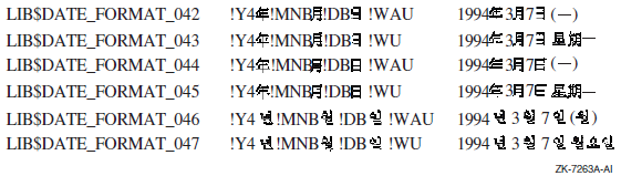
Note
LIB$DATE_FORMAT_042 and LIB$DATE_FORMAT_043 support the DEC Hanzi coded character set.
LIB$DATE_FORMAT_044 and LIB$DATE_FORMAT_045 support the DEC Hanyu coded character set.
LIB$DATE_FORMAT_046 and LIB$DATE_FORMAT_047 support the DEC Hangul coded character set.
Figure 11.2, ''Predefined Output Time Formats'' lists the new predefined time format logical names in the first column, their formats in the second column, and examples of the output generated using these formats in the third column.
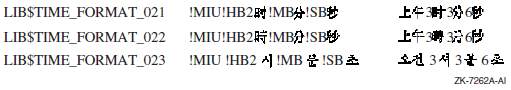
Note
LIB$TIME_FORMAT_021 supports the DEC Hanzi coded character set.
LIB$TIME_FORMAT_022 supports the DEC Hanyu coded character set.
LIB$TIME_FORMAT_023 supports the DEC Hangul coded character set.
LIB$DATE_FORMAT_nnn, where nnn can range from 001 to 047
LIB$TIME_FORMAT_nnn, where nnn can range from 001 to 023
11.6.2. Selecting a Format
The language and format are determined at run time through the translation of the logical names SYS$LANGUAGE, LIB$DT_FORMAT, an dLIB$DT_INPUT_FORMAT.
The language and format are programmable at compile time through the use of the LIB$INIT_DATE_TIME_CONTEXT routine.
In general, if an application accepts text from a user or formats text for presentation to a user, you should use the logical name method of specifying language and format. With this method, the user assigns equivalence names to the logical names SYS$LANGUAGE, LIB$DT_FORMAT, and LIB$DT_INPUT_FORMAT, thereby selecting the language and input or output format of the date and time at run time.
If an application reads text from internal storage or formats text for internal storage or transmission, the language and format should be specified at compile time. If this is the case, the routine LIB$INIT_DATE_TIME_CONTEXT specifies the language and format of choice.
11.6.2.1. Formatting Run-Time Mnemonics
|
Date |
Explanation |
|---|---|
|
!D0 |
Day; zero-filled |
|
!DD |
Day; no fill |
|
!DB |
Day; blank-filled |
|
!WU |
Weekday; uppercase |
|
!WAU |
Weekday; abbreviated, uppercase |
|
!WC |
Weekday; capitalized |
|
!WAC |
Weekday; abbreviated, capitalized |
|
!WL |
Weekday; lowercase |
|
!WAL |
Weekday; abbreviated, lowercase |
|
!MAU |
Month; alphabetic, uppercase |
|
!MAAU |
Month; alphabetic, abbreviated, uppercase |
|
!MAC |
Month; alphabetic, capitalized |
|
!MAAC |
Month; alphabetic, abbreviated, capitalized |
|
!MAL |
Month; alphabetic, lowercase |
|
!MAAL |
Month; alphabetic, abbreviated, lowercase |
|
!MN0 |
Month; numeric, zero-filled |
|
!MNM |
Month; numeric, no fill |
|
!MNB |
Month; numeric, blank-filled |
|
!Y4 |
Year; 4 digits |
|
!Y3 |
Year; 3 digits |
|
!Y2 |
Year; 2 digits |
|
!Y1 |
Year; 1 digit |
|
!Z4 |
Year; 4 digits |
|
!Z3 |
Year; 3 digits |
|
!Z2 |
Year; 2 digits (see LIB$CONVERT_DATE_STRING) |
|
!Z1 |
Year; 1 digit |
|
Time |
Explanation |
|
!H04 |
Hours; zero-filled, 24-hour clock |
|
!HH4 |
Hours; no fill, 24-hour clock |
|
!HB4 |
Hours; blank-filled, 24-hour clock |
|
!H02 |
Hours; zero-filled, 12-hour clock |
|
!HH2 |
Hours; no fill, 12-hour clock |
|
!HB2 |
Hours; blank-filled, 12-hour clock |
|
!M0 |
Minutes; zero-filled |
|
!MM |
Minutes; no fill |
|
!MB |
Minutes; blank-filled |
|
!S0 |
Seconds; zero-filled |
|
!SS |
Seconds; no fill |
|
!SB |
Seconds; blank-filled |
|
!C7 |
Fractional seconds; 7 digits |
|
!C6 |
Fractional seconds; 6 digits |
|
!C5 |
Fractional seconds; 5 digits |
|
!C4 |
Fractional seconds; 4 digits |
|
!C3 |
Fractional seconds; 3 digits |
|
!C2 |
Fractional seconds; 2 digits |
|
!C1 |
Fractional seconds; 1 digit |
|
!MIU |
Meridiem indicator; uppercase |
|
!MIC |
Meridiem indicator; capitalized (mixed case) |
|
!MIL |
Meridiem indicator; lowercase |
11.6.2.2. Specifying Formats at Run Time
If an application accepts text from a user or formats text for presentation to a user, you should use the logical name method of specifying language and format. With this method, the user assigns equivalence names to the logical names SYS$LANGUAGE, LIB$DT_FORMAT, and LIB$DT_INPUT_FORMAT, thereby selecting the language and format of the date and time at run time. LIB$DT_INPUT_FORMAT must be defined using the mnemonics listed in Table 11.6, ''Format Mnemonics''.The possible choices for SYS$LANGUAGE and LIB$DT_FORMAT are defined in the SYS$MANAGER:LIB$DT_STARTUP.COM command procedure that is executed by the system manager before using these routines.
If the translation of SYS$LANGUAGE or any logical name relating to text fails, then English is used and a status of LIB$_ENGLUSED is returned.
If the translation of LIB$DT_FORMAT, LIB$DT_INPUT_FORMAT, or any logical name relating to format fails, the operating system standard (SYS$ASCTIM) representation of the date and time is used, that is, dd-MMM-yyyy hh:mm:ss.cc, and a status of LIB$_DEFFORUSE is returned.
Since English is the default language and must therefore always be available, English spellings are not taken from logical name translations, but rather are looked up in an internal table.
11.6.2.3. Specifying Input Formats at Run Time
$ DEFINE LIB$DT_INPUT_FORMAT -
_$ "!MAU !DD, !Y4 !H02:!M0:!S0:!C2 !MIU"JUNE 15, 1993 08:45:06:50 PM
If the user has selected a language other than English, then the translation of SYS$LANGUAGE is used by the parser to recognize alphabetic months and meridiem indicators in the selected language.
Input Format String
Month (either alphabetic or numeric)
Day of the month (numeric)
Year (from 1 to 4 digits)
Hour (12- or 24-hour clock)
Minute of the hour
Second of the minute
Fractional seconds
Meridiem indicator (required for 12-hour clock; illegal for 24-hour clock)
If the input format string specifies a 24-hour clock, the string contains only the first seven fields in the preceding list. If a 12-hour clock is specified, the eighth field (the meridiem indicator) is required.
!MAU !DD, !Y4 !H02:!M0:!S0:!C2 !MIUIf the input string corresponding to this format string contains a month name that is abbreviated and lowercase, the parse of the input string still works correctly. For example:
feb 25, 1988 04:39:02:55 am
If this input string is entered, the parse still recognizes "feb" as the month name and "am" as the meridiem indicator, even though the format string specified both of these fields as uppercase, and the month name as unabbreviated.
Punctuation in the Format and Input Strings
One important aspect to consider when formatting date/time input strings is punctuation. The punctuation referred to here is the characters that separate the various date/time fields or the date and time groups. Punctuation in these strings is important because it is used as an outline for the parser, allowing the parser to synchronize the input fields to the format fields.
None Although it is common for no punctuation to begin or end an input format string, you can specify a date/time format that also has no punctuation between the fields or groups of the format string. If this is the case, the corresponding input string must not have any punctuation between the respective fields or groups, although white space (see the next item in this list) may appear at the beginning or end of the input string.
White space White space includes any combination of spaces and tabs. In the interpretation of the format string, any white space is condensed to a single space. When parsing an input string, white space is generally noted as synchronizing punctuation and is skipped; however, white space is significant in some situations, such as with blank-filled numbers.
Explicit punctuation refers to any string of one or more characters that is used as punctuation and is not solely comprised of white space. Any white space appearing within an explicit punctuation string is interpreted literally; in other words, the white space is not compressed. In the format string, you can use explicit punctuation to denote a particular format and to guide the parser in parsing the input string. In the input string, you can use explicit punctuation to synchronize the parse of the input string against the format string. The explicit punctuation used should not be a subset of the valid input of any field that it precedes or follows it.
Punctuation is especially important in providing guidelines for the parser to translate the input date/time string properly.
Default Date/Time Fields
For the date group, the default is the current date.
For the time group, the default is 00:00:00.00.
|
Input |
Full Date/Time Input String |
|---|---|
|
31 |
31-FEB-1993 00:00:00.00 |
|
-MAR |
25-MAR-1993 00:00:00.00 |
|
-SEPTEMBER |
25-SEP-1993 00:00:00.00 |
|
-1993 |
25-FEB-1993 00:00:00.00 |
|
23: |
25-FEB-1993 23:00:00.00 |
|
:45: |
25-FEB-1993 00:45:00.00 |
|
::23 |
25-FEB-1993 00:00:23.00 |
|
.01 |
25-FEB-1993 00:00:00.01 |
Note on the Changing Century
Because the default is the current date for the date group, if you specify a value of 00 with the !Y2 format, the year is interpreted as 1900. After January 1, 2000, the value 00 will be interpreted as 2000.
For example, 02/29/00 is interpreted as 29-FEB-1900, which results in LIB$_INVTIME because 1900 is not a leap year. After the turn of the century (the year 2000), 02/29/00 will be 29-FEB-2000, which is a valid date because 2000 is a leap year.
11.6.2.4. Specifying Output Formats at Run Time
If the logical name method is used to specify an output format at runtime, the translations of the logical names SYS$LANGUAGE and LIB$DT_FORMAT specify one or more executive mode logical names which in turn must be translated to determine the actual format string. These additional logical names supply such things as the names of the days of the week and the months in the selected language (as determined by SYS$LANGUAGE). All of these logicals are predefined, so that a nonprivileged user can select any one of these languages and formats. In addition, a user can create his or her own languages and formats; however, the CMEXEC, SYSNAM and SYSPRV privileges are required.
LIB$DATE_FORMAT_nnn, where nnn ranges from 001 to 040
LIB$TIME_FORMAT_nnn, where nnn ranges from 001 to 020
$ DEFINE LIB$DT_FORMAT LIB$DATE_FORMAT_006, LIB$TIME_FORMAT_012
13 JAN 93 9:13 AM
|
Date Format Logical Name |
Format |
Example |
|---|---|---|
|
LIB$DATE_FORMAT_001 |
!DB-!MAAU-!Y4 |
13-JAN-1993 |
|
LIB$DATE_FORMAT_002 |
!DB !MAU !Y4 |
13 JANUARY 1993 |
|
LIB$DATE_FORMAT_003 |
!DB.!MAU !Y4 |
13.JANUARY 1993 |
|
LIB$DATE_FORMAT_004 |
!DB.!MAU.!Y4 |
13.JANUARY.1993 |
|
LIB$DATE_FORMAT_005 |
!DB !MAU !Y2 |
13 JANUARY 93 |
|
LIB$DATE_FORMAT_006 |
!DB !MAAU !Y2 |
13 JAN 93 |
|
LIB$DATE_FORMAT_007 |
!DB.!MAAU !Y2 |
13.JAN 93 |
|
LIB$DATE_FORMAT_008 |
!DB.!MAAU.!Y2 |
13.JAN.93 |
|
LIB$DATE_FORMAT_009 |
!DB !MAAU !Y4 |
13 JAN 1993 |
|
LIB$DATE_FORMAT_010 |
!DB.!MAAU !Y4 |
13.JAN 1993 |
|
LIB$DATE_FORMAT_011 |
!DB.!MAAU.!Y4 |
13.JAN.1993 |
|
LIB$DATE_FORMAT_012 |
!MAU !DD, !Y4 |
JANUARY 13, 1993 |
|
LIB$DATE_FORMAT_013 |
!MN0/!D0/!Y2 |
01/13/93 |
|
LIB$DATE_FORMAT_014 |
!MN0-!D0-!Y2 |
01-13-93 |
|
LIB$DATE_FORMAT_015 |
!MN0.!D0.!Y2 |
01.13.93 |
|
LIB$DATE_FORMAT_016 |
!MN0 !D0 !Y2 |
01 13 93 |
|
LIB$DATE_FORMAT_017 |
!D0/!MN0/!Y2 |
13/01/93 |
|
LIB$DATE_FORMAT_018 |
!D0/!MN0-!Y2 |
13/01-93 |
|
LIB$DATE_FORMAT_019 |
!D0-!MN0-!Y2 |
13-01-93 |
|
LIB$DATE_FORMAT_020 |
!D0.!MN0.!Y2 |
13.01.93 |
|
LIB$DATE_FORMAT_021 |
!D0 !MN0 !Y2 |
13 01 93 |
|
LIB$DATE_FORMAT_022 |
!Y2/!MN0/!D0 |
93/01/13 |
|
LIB$DATE_FORMAT_023 |
!Y2-!MN0-!D0 |
93-01-13 |
|
LIB$DATE_FORMAT_024 |
!Y2.!MN0.!D0 |
93.01.13 |
|
LIB$DATE_FORMAT_025 |
!Y2 !MN0 !D0 |
93 01 13 |
|
LIB$DATE_FORMAT_026 |
!Y2!MN0!D0 |
930113 |
|
LIB$DATE_FORMAT_027 |
/!Y2.!MN0.!D0 |
/93.01.13 |
|
LIB$DATE_FORMAT_028 |
!MN0/!D0/!Y4 |
01/13/1993 |
|
LIB$DATE_FORMAT_029 |
!MN0-!D0-!Y4 |
01-13-1993 |
|
LIB$DATE_FORMAT_030 |
!MN0.!D0.!Y4 |
01.13.1993 |
|
LIB$DATE_FORMAT_031 |
!MN0 !D0 !Y4 |
01 13 1993 |
|
LIB$DATE_FORMAT_032 |
!D0/!MN0/!Y4 |
13/01/1993 |
|
LIB$DATE_FORMAT_033 |
!D0-!MN0-!Y4 |
13-01-1993 |
|
LIB$DATE_FORMAT_034 |
!D0.!MN0.!Y4 |
13.01.1993 |
|
LIB$DATE_FORMAT_035 |
!D0 !MN0 !Y4 |
13 01 1993 |
|
LIB$DATE_FORMAT_036 |
!Y4/!MN0/!D0 |
1993/01/13 |
|
LIB$DATE_FORMAT_037 |
!Y4-!MN0-!D0 |
1993-01-13 |
|
LIB$DATE_FORMAT_038 |
!Y4.!MN0.!D0 |
1993.01.13 |
|
LIB$DATE_FORMAT_039 |
!Y4 !MN0 !D0 |
1993 01 13 |
|
LIB$DATE_FORMAT_040 |
!Y4!MN0!D0 |
19930113 |
| Time Format Logical | Format | Example |
|---|---|---|
|
LIB$TIME_FORMAT_001 |
!H04:!M0:!S0.!C2 |
09:13:25.14 |
|
LIB$TIME_FORMAT_002 |
!H04:!M0:!S0 |
09:13:25 |
|
LIB$TIME_FORMAT_003 |
!H04.!M0.!S0 |
09.13.25 |
|
LIB$TIME_FORMAT_004 |
!H04 !M0 !S0 |
09 13 25 |
|
LIB$TIME_FORMAT_005 |
!H04:!M0 |
09:13 |
|
LIB$TIME_FORMAT_006 |
!H04.!M0 |
09.13 |
|
LIB$TIME_FORMAT_007 |
!H04 !M0 |
09 13 |
|
LIB$TIME_FORMAT_008 |
!HH4:!M0 |
9:13 |
|
LIB$TIME_FORMAT_009 |
!HH4.!M0 |
9.13 |
|
LIB$TIME_FORMAT_010 |
!HH4 !M0 |
9 13 |
|
LIB$TIME_FORMAT_011 |
!H02:!M0 !MIU |
09:13 AM |
|
LIB$TIME_FORMAT_012 |
!HH2:!M0 !MIU |
9:13 AM |
|
LIB$TIME_FORMAT_013 |
!H04!M0 |
0913 |
|
LIB$TIME_FORMAT_014 |
!H04H!M0m |
09H13m |
|
LIB$TIME_FORMAT_015 |
kl !H04.!M0 |
kl 09.13 |
|
LIB$TIME_FORMAT_016 |
!H04H!M0' |
09H13' |
|
LIB$TIME_FORMAT_017 |
!H04.!M0 h |
09.13 h |
|
LIB$TIME_FORMAT_018 |
h !H04.!M0 |
h 09.13 |
|
LIB$TIME_FORMAT_019 |
!HH4 h !MM |
9 h 13 |
|
LIB$TIME_FORMAT_020 |
!HH4 h !MM min !SS s |
9 h 13 min 25 s |
11.6.2.5. Specifying Formats at Compile Time
If an application reads text from internal storage or formats text for internal storage or transmission, you should specify the language and format at compile time. The routine LIB$INIT_DATE_TIME_CONTEXT allows the user to specify the language and format at compile time by initializing the context area used by LIB$FORMAT_DATE_TIME for output or LIB$CONVERT_DATE_STRING for input with specific strings, instead of through logical name translations. Note that when the text will be parsed by another program, LIB$INIT_DATE_TIME_CONTEXT expects all required context information (including spellings) to be specified. For applications where the context specifies a user's preferred format style, the spellings can be looked up from the logical name tables.
|
Available Component |
Number of Elements |
|---|---|
|
LIB$K_MONTH_NAME |
12 |
|
LIB$K_MONTH_NAME_ABB |
12 |
|
LIB$K_FORMAT_MNEMONICS |
9 |
|
LIB$K_WEEKDAY_NAME |
7 |
|
LIB$K_WEEKDAY_NAME_ABB |
7 |
|
LIB$K_RELATIVE_DAY_NAME |
3 |
|
LIB$K_MERIDIEM_INDICATOR |
2 |
|
LIB$K_OUTPUT_FORMAT |
2 |
|
LIB$K_INPUT_FORMAT |
1 |
|
LIB$K_LANGUAGE |
1 |
"[delim][string-1][delim][string-2][delim]...[delim][string-n][delim]"
In this format, [-] is a delimiting character that is not in any of the strings, and [string-n] is the spelling of the nth instance of the component.
"|JAN|FEB|MAR|APR|MAY|JUN
 |JUL|AUG|SEP|OCT|NOV|DEC|"
The string must contain the exact number of elements for the associated component; otherwise the error LIB$_NUMELEMENTS is returned. Note that the string begins and ends with a delimiter. Thus, there is one more delimiter than the number of string elements in the initialization string.
11.6.2.6. Specifying Input Format Mnemonics at Compile Time
|
Order |
Format Field |
Legible Mnemonic (Default) |
|---|---|---|
|
1 |
Year |
YYYY |
|
2 |
Numeric month |
MM |
|
3 |
Numeric day |
DD |
|
4 |
Hours (12- or 24-hour) |
HH |
|
5 |
Minutes |
MM |
|
6 |
Seconds |
SS |
|
7 |
Fractional seconds |
CC |
|
8 |
Meridiem indicator |
AM/PM |
|
9 |
Alphabetic month |
MONTH |
|YYYY|MM|DD|HH|MM|SS|CC|AM/PM|MONTH|
|JJJJ|MM|TT|SS|MM|SS|HH| |MONAT|
11.6.2.7. Specifying Output Formats at Compile Time
To specify an output format at compile time, the user must preinitialize the component LIB$K_OUTPUT_FORMAT. Two elements are associated with this output format string. One describes the date format fields, the other the time format fields. The order in which they appear in the string determines the order in which they are output. A single space is inserted into the output stream between the two elements, if the call to LIB$FORMAT_DATE_TIME specifies that both be output. For example:
" |!DB-!MAAU-!Y4 |!H04:!M0:!S0.!C2 |"
13-JAN-1993 14:54:09:24
11.6.3. Converting with the LIB$CONVERT_DATE_STRING Routine
The LIB$CONVERT_DATE_STRING routine converts an absolute
date/time string into an operating system internal format date/time quadword. You
can optionally specify which fields of the input string can be defaulted (using the
input-flags argument), and what the default values should
be (using the defaults argument). By default, the time fields
can be defaulted but the date fields cannot. Table 11.7, ''Input String Punctuation and Defaults''
gives some examples of these default values.
You can use the optional defaulted-fields argument to
LIB$CONVERT_DATE_STRING to determine which input fields
were defaulted. That is, the defaulted-fields argument is a
bit mask in which each set bit indicates that the corresponding field was defaulted
in the input date/time string.
If you want to use LIB$CONVERT_DATE_STRING to return the
current time as well as the current date, you can call the
$NUMTIM system service and pass the
timbuf argument, which contains the current date and
time, to LIB$CONVERT_DATE_STRING as the
defaultsargument. This tells the
LIB$CONVERT_DATE_STRING routine to take the default
values for the date and time fields from the 7-word array returned by
$NUMTIM.
LIV$CONVERT_DATE_STRING specifies 2-digit years from input by selecting the current century as the default for the century portion of the date. This is true when the !Y2 format is used. This selection may not be desirable for you since 00 would be interpreted as 1900 (and as 2000 on 1/1/2000).
init-string parameter for a call to
LIB$INIT_DATE_TIME_CONTEXT to establish the input
format for LIB$CONVERT_DATE_STRING. Below is a list of the
new Z formats:|
Date |
Explanation |
|---|---|
|
!Z4 |
Year; 4 digits |
|
!Z3 |
Year; 3 digits |
|
!Z2 |
Year; 2 digits (New behavior for the LIB$CONVERT_DATE_STRING routine) |
|
!Z1 |
Year; 1 digit |
11.6.4. Retrieving with LIB$GET_DATE_FORMAT Routine
The LIB$GET_DATE_FORMAT routine enables you to retrieve information about the currently selected input format. The string returned by LIB$GET_DATE_FORMAT parallels the currently defined input format string, consisting of the format punctuation (with most white space compressed) and legible mnemonics representing the various format fields.
Based on the currently defined input date/time format, LIB$GET_DATE_FORMAT returns a string comprised of the mnemonics that represent the current format. These mnemonics are listed in Table 11.11, ''Legible Format Mnemonics''.
|
Sample Format String |
LIB$GET_DATE_FORMAT Value |
|---|---|
|
!MAU !DD, !Y4 !H04:!M0:!S0:!C2 |
MONTH DD, YYYY4 HH:MM:SS:CC2 |
|
!MN0-!D0-!Y2 !H04:!M0:!S0.!C2 |
MM-DD-YYYY2 HH:MM:SS.CC2 |
|
!MN0/!D0/!Y2 !H02:!M0:!S0.!C2 !MIU |
MM/DD/YYYY2 HH:MM:SS.CC2 AM/PM |
11.6.4.1. Using User-Defined Output Formats
In addition to the 40 date output formats and 20 time output formats, users can define their own date and time output formats using the logical names LIB$DATE_FORMAT_nnn and LIB$TIME_FORMAT_nnn, where nnn ranges from 501 to 999. (That is, values of nnn from 001 to 500 are reserved for use by OpenVMS.) The mnemonics used to define output formats are listed in Table 11.6, ''Format Mnemonics''.
$ DEFINE/EXEC/TABLE=LNM$DT_FORMAT_TABLE LIB$DATE_FORMAT_501 -
_$  "!WL, le !DD !MAL !Y4"
$ DEFINE/EXEC/TABLE=LNM$DT_FORMAT_TABLE LIB$TIME_FORMAT_501 -
_$  "!H04 heures et !M0 minutes"
$ DEFINE SYS$LANGUAGE FRENCH
$ DEFINE LIB$DT_FORMAT LIB$DATE_FORMAT_501, LIB$TIME_FORMAT_501
After completing these steps, a program outputting the date and time provides the following results:
mardi, le 20 janvier 1993 13 heures et 50 minutes
In addition to creating their own date and time formats, users can also define their own language tables (provided they have the SYSNAM, SYSPRV and CMEXEC privileges). To create a language table, a user must define all the logical names required.
$ CREATE/NAME/PARENT=LNM$SYSTEM_DIRECTORY/EXEC/PROT=(S:RWED,G:R,W:R) -
_$  LNM$LANGUAGE_DUTCH
$ DEFINE/EXEC/TABLE=LNM$LANGUAGE_DUTCH LIB$WEEKDAYS_L -
_$  "maandag", "dinsdag", "woensdag", "donderdag", "vrijdag", -
_$  "zaterdag", "zondag"
$ DEFINE/EXEC/TABLE=LNM$LANGUAGE_DUTCH LIB$WEEKDAY_ABBREVIATIONS_L -
_$  "maa", "din", "woe", "don", "vri", "zat", "zon"
$ DEFINE/EXEC/TABLE=LNM$LANGUAGE_DUTCH LIB$MONTHS_L "januari", -
_$  "februari", "maart", "april", "mei", "juni", "juli", "augustus", -
_$  "september", "oktober", "november", "december"
$ DEFINE/EXEC/TABLE=LNM$LANGUAGE_DUTCH LIB$MONTH_ABBREVIATIONS_L -
_$  "jan", "feb", "mrt", "apr", "mei", "jun", "jul", "aug", "sep", -
_$  "okt", "nov", "dec"
$ DEFINE/EXEC/TABLE=LNM$LANGUAGE_AUSTRIAN LIB$RELATIVE_DAYS_L -
_$  "gisteren", "vandaag", "morgen"
All logical names that are used to build a language are as follows:
LIB$WEEKDAYS_[U |L |C] These logical names supply the names of the weekdays, spelled out in full (uppercase, lowercase, or mixed case). Weekdays must be defined in order, starting with Monday.
LIB$WEEKDAY_ABBREVIATIONS_[U |L |C] These logical names supply the abbreviated names of the weekdays (uppercase, lowercase, or mixed case). Weekday abbreviations must be defined in order, starting with Monday.
LIB$MONTHS_[U |L |C] These logical names supply the names of the months, spelled out in full (uppercase, lowercase, or mixed case). Months must be defined in order, starting with January.
LIB$MONTH_ABBREVIATIONS_[U |L
                        |C]
These logical names supply the abbreviated names of the months (uppercase, lowercase, or mixed case). Month abbreviations must be defined in order, starting with January.
LIB$MI_[U |L |C] These logical names supply the spellings for the meridiem indicators (uppercase, lowercase, or mixed case). Meridiem indicators must be defined in order; the first indicator represents the hours 0:00:0.0 to 11:59:59.99, and the second indicator represents the hours 12:00:00.00 to 23:59:59.99.
LIB$RELATIVE_DAYS_[U |L |C] These logical names supply the spellings for the relative days (uppercase, lowercase, or mixed case). Relative days must be defined in order:yesterday, today, and tomorrow, respectively.
LIB$FORMAT_MNEMONICS Year (YYYY)
Numeric month (MM)
Day of the month (DD)
Hour of the day (HH)
Minutes of the hour (MM)
Seconds of the minute (SS)
Parts of the second (CC)
Meridiem indicator (AM/PM)
Alphabetic month (MONTH)
$ DEFINE/EXEC/TABLE=LNM$LANGUAGE_ENGLISH LIB$FORMAT_MNEMONICS -
_$  "YYYY", "MM", "DD", "HH", "MM", "SS", "CC", "AM/PM ", "MONTH"
11.7. Coordinated Universal Time Format
This section provides information about VAX systems that supply system base date and time format other than the Smithsonian base date and time system. The other base date and time format system is the Coordinated Universal Time (UTC) system. UTC time is determined by a network of atomic clocks that are maintained by standard bodies in several countries. Formerly, applications that spanned time zones often used Greenwich Mean Time (GMT) as a time reference.
UTC binary timestamps are opaque octawords of 128-bits that contain several fields. Important fields of the UTC format are an absolute time value, a time differential factor (TDF) that contains the offset of the host node's clock from UTC, and an inaccuracy, or tolerance, that can be applied to the absolute time value. Unlike UTC, the operating system binary date and timestamps in the Smithsonian base date and time format represent only the local time of the host node; they do not contain TDF values or inaccuracy values.
The UTC system services allow applications to gain the benefits of a Coordinated Universal Time reference. The UTC system services enable applications to reference a common time standard independent of the host's location and local date and time value.
Obtain binary representations of UTC in the binary UTC format
Convert the binary operating system format date and time to binary UTC-formatdate and time
Convert binary UTC-format date and time to the binary operating system date and time
Convert ASCII-format date and time to binary UTC-format date and time
Convert binary UTC-format date and time to ASCII-format date and time
SYS$ASCUTC – Convert UTC to ASCII
SYS$BINUTC – Convert ASCII String to UTC Binary Time
SYS$GETUTC – Get UTC Time
SYS$NUMUTC – Convert UTC Time to Numeric Components
SYS$TIMCON – Time Converter
For specific implementation information about the UTC system services, see the VSI OpenVMS System Services Reference Manual.
Chapter 12. File Operations
This chapter describes file operations that support file input/output (I/O) and file I/O instructions of the operating system's high-level languages.
Note
Some confusion might arise between records in a file and record variables. Where this chapter refers to a record variable, the term record variable is used; otherwise, record refers to a record in a file.
12.1. File Attributes
Before writing a program that accesses a data file, you must know the attributes of the file and the order of the data. To determine this information, see your language-specific programming manual.
File attributes (organization, record structure, and so on) determine how data is stored and accessed. Typically, the attributes are specified by keywords when you open the data file.
Ordering of the data within a file is not important mechanically. However, if you attempt to read data without knowing how it is ordered within the file, you are likely to read the wrong data; if you attempt to write data without knowing how it is ordered within the file, you are likely to corrupt existing data.
12.1.1. Specifying File Attributes
You can specify large sets of attributes using the File Definition Language utility (FDL). You can specify all of the file attributes using OpenVMS RMS in a user-open routine (see Section 12.6, ''User-Open Routines''). Typically, you need only programming language file specifiers. Use FDL only when language specifiers are unavailable.
Refer to the appropriate programming language reference manual for information about the use of language specifiers.
For complete information about how to use FDL, see the VSI OpenVMS Record Management Utilities Reference Manual.
12.2. File Access Strategies
Complete access
If your program processes all or most of the data in the file and especially if many references are made to the data, you should read the entire file into memory. Put each record in its own variable or set of variables.
If your program is larger than the amount of virtual memory available (including the additional memory you get by using memory allocation routines), you must declare fewer variables and process your file in pieces. To determine the size of your program, add the number of bytes in each program section. The DCL command LINK/MAP produces a listing that includes the length of each program section (PSECT).
Record-by-record access
If your program accesses records one after another, or if you cannot fit the entire file into memory, you should read one record into memory at a time.
Discrete records access
If your program processes only a selection of the file's records, you should read only the necessary records into memory.
Sequential and indexed file access
If your program demands speed and needs to conserve disk space, use an unformatted sequential file. Use indexed files either to process selected sets of records or to access records directly. Use either a sequential file with fixed-length records, a relative file, or an indexed file to access records directly.
12.3. File Protection and Access
Files are owned by the process that creates them and receive the default protection of the creating process. To create a file with ownership and protection other than the default, use the File Definition Language (FDL) attributes OWNER and PROTECTION in the file.
12.3.1. Read-Only Access
By default, the user of your program must have write access to a file in order for your program to open that file. However, if you specify use of the Fortran READONLY specifier when opening the file, the user needs only read access to the file to open it. The READONLY specifier does not set the protection on a file. The user cannot write to a file opened with the READONLY specifier.
12.3.2. Shared Access
The Fortran specifier READONLY and the SHARED specifier allow multiple processes to open the same file simultaneously, provided that each process uses one of these specifiers when opening the file. The READONLY specifier allows the process read access to the file; the SHARED specifier allows other processes read and write access to the file. If a process opens the file without specifying READONLY or SHARED, no other process can open that file even by specifying READONLY or SHARED.
! Status variables and values
INTEGER STATUS,
2       IOSTAT,
2       IO_OK
PARAMETER (IO_OK = 0)
INCLUDE '($FORDEF)'
! Logical unit number
INTEGER LUN /1/
! Record variables
INTEGER LEN
CHARACTER*80 RECORD
   .
   .
   .
READ (UNIT = LUN,
2     FMT = '(Q,A)'
2     IOSTAT = IOSTAT) LEN, RECORD (1:LEN)
IF (IOSTAT .NE. IO_OK) THEN
  CALL ERRSNS (,,,,STATUS)
   IF (STATUS .EQ. FOR$_SPERECLOC) THEN
     DO WHILE (STATUS .EQ. FOR$_SPERECLOC)
     READ (UNIT = LUN,
2          FMT = '(Q,A)'
2          IOSTAT = IOSTAT) LEN, RECORD(1:LEN)
     IF (IOSTAT .NE. IO_OK) THEN
           CALL ERRSNS (,,,,STATUS)
           IF (STATUS .NE. FOR$_SPERECLOC) THEN
                CALL LIB$SIGNAL(%VAL(STATUS))
           END IF
     END IF
     END DO
ELSE
   CALL LIB$SIGNAL (%VAL(STATUS))
   END IF
END IF
   .
   .
   .
In Fortran, each time you access a record in a shared file, that record is automatically locked either until you perform another I/O operation on the same logical unit, or until you explicitly unlock the record using the UNLOCK statement. If you plan to modify a record, you should do so before unlocking it; otherwise, you should unlock the record as soon as possible.
12.4. File Access and Mapping
To copy an entire data file from the disk to program variables and back again, either use language I/O statements to read and write the data or use the Create and Map Section (SYS$CRMPSC) system service to map the data. Often times, mapping the file is faster than reading it. However, a mapped file usually uses more virtual memory than one that is read using language I/O statements. Using I/O statements, you have to store only the data that you have entered. Using SYS$CRMPSC, you have to initialize the database and store the entire structure in virtual memory including the parts that do not yet contain data.
12.4.1. Using SYS$CRMPSC
Note
Files created using OpenVMS RMS typically contain control information. Unless you are familiar with the structure of these files, do not attempt to map one. The best practice is to map only those files that have been created as the result of mapping.
Place the program variables for the data in a common block. Page align the common block at link time by specifying an options file containing the following link option for VAX, Alpha, and IA-64 systems:
For VAX systems, specify the following:PSECT_ATTR = name, PAGE
For Alpha and IA-64 systems, specify the following:PSECT_ATTR = name, solitary
The variable
nameis the name of the common block.Within the common block, you should specify the data in order from most complex to least complex (high to low rank), with character data last. This naturally aligns the data, thus preventing troublesome page breaks in virtual memory.
Open the data file using a user-open routine. The user-open routine must open the file for user I/O (as opposed to OpenVMS RMS I/O) and return the channel number on which the file is opened.
Map the data file to the common block.
Process the records using the program variables in the common block.
Free the memory used by the common block, forcing modified data to be written back to the disk file.
Do not initialize variables in a common block that you plan to map; the initial values will be lost when SYS$CRMPSC maps the common block.
12.4.1.1. Mapping a File
SYS$CRMPSC
  [inadr],[retadr],[acmode],[flags],[gsdnam],[ident],[relpag],
  [chan], [pagcnt],[vbn],[prot],[pfc]
For a complete description of the SYS$CRMPSC system service, see the VSI OpenVMS System Services Reference Manual.
Starting and Ending Addresses of the Mapped Section
On VAX systems, specify the location of the first variable in the common block
as the value of the first array element of the array passed by the
inadr argument. Specify the location of the last
variable in the common block as the value of the second array element.
On Alpha and IA-64 systems, specify the location of the first variable in the
common block as the value of the first array element of the array passed by the
inadr argument; the second array element must be the
address of the last variable in the common block, which is derived by performing
a logical OR with the value of the size of a memory page minus 1. The size of
the memory page can be retrieved by a call to the
SYS$GETSYI system service.
If the first variable in the common block is an array or string, the first variable in the common block is the first element of that array or string. If the last variable in the common block is an array or string, the last variable in the common block is the last element in that array or string.
Returning the Location of the Mapped Section
On VAX systems, SYS$CRMPSC returns the location of
the first and last elements mapped in the retadr
argument. The value returned as the starting virtual address should be the same
as the starting address passed to the inadr argument. The
value returned as the ending virtual address should be equal to or slightly more
than (within 512 bytes, or 1 block) the value of the ending virtual address
passed to the inadr argument.
On Alpha and IA-64 systems, SYS$CRMPSC returns the
location of the first and last elements mapped in the
retadr argument. The value returned as the starting
virtual address should be the same as the starting address passed to the
inadr argument. The value returned as the ending
virtual address should be equal to or slightly less than (within a single page
size) the value of the ending virtual address passed to the
inadr argument.
If the first element is in error, you probably forgot to page-align the common block containing the mapped data.
If the second element is in error, you were probably creating a new data file and forgot to specify the size of the file in your program (see Section 12.4.1.3, ''Initializing a Mapped Database'').
Using Private Sections
Specify SEC$M_WRT for the
flags to indicate that the section is writable. If
the file is new, also specify SEC$M_DZRO to indicate
that the section should be initialized to zero.
Obtaining the Channel Number
You must use a user-open routine to get the channel number (see Section 12.4.1.2, ''Using the User-Open Routine''). Pass the channel number to the
chan argument.
On VAX systems, Example 12.1, ''Mapping a Data File to the Common Block on a VAX System'' maps a data file consisting of one longword and three real arrays to the INC_DATA common block. The options file INCOME.OPT page-aligns the INC_DATA common block.
!INCOME.OPT

PSECT_ATTR = INC_DATA, PAGE
INCOME.FOR
! Declare variables to hold statistics
REAL PERSONS_HOUSE (2048),
2    ADULTS_HOUSE (2048),
2    INCOME_HOUSE (2048)
INTEGER TOTAL_HOUSES
! Declare section information
! Data area
COMMON /INC_DATA/ PERSONS_HOUSE,
2                 ADULTS_HOUSE,
2                 INCOME_HOUSE,
2                 TOTAL_HOUSES
! Addresses
INTEGER ADDR(2),
2       RET_ADDR(2)
! Section length
INTEGER SEC_LEN
! Channel
INTEGER*2 CHAN,
2         GARBAGE
COMMON /CHANNEL/ CHAN,
2                GARBAGE
! Mask values
INTEGER MASK
INCLUDE '($SECDEF)'
! User-open routines
INTEGER UFO_OPEN,
2       UFO_CREATE
EXTERNAL UFO_OPEN,
2        UFO_CREATE
! Declare logical unit number
INTEGER STATS_LUN
! Declare status variables and values
INTEGER STATUS,
2       IOSTAT,
2       IO_OK
PARAMETER (IO_OK = 0)
INCLUDE '($FORDEF)'
EXTERNAL INCOME_BADMAP
! Declare logical for INQUIRE statement
LOGICAL EXIST
! Declare subprograms invoked as functions
INTEGER LIB$GET_LUN,
2       SYS$CRMPSC,
2       SYS$DELTVA,
2       SYS$DASSGN
! Get logical unit number for STATS.SAV
STATUS = LIB$GET_LUN (STATS_LUN)
IF (.NOT. STATUS) CALL LIB$SIGNAL (%VAL (STATUS))
INQUIRE (FILE = 'STATS.SAV',
2        EXIST = EXIST)
IF (EXIST) THEN
  OPEN (UNIT=STATS_LUN,
2       FILE='STATS.SAV',
2       STATUS='OLD',
2       USEROPEN = UFO_OPEN)
  MASK = SEC$M_WRT
ELSE
  ! If STATS.SAV does not exist, create new database
  MASK = SEC$M_WRT .OR. SEC$M_DZRO
  SEC_LEN =
!  (address of last - address of first + size of last + 511)/512
2  ( (%LOC(TOTAL_HOUSES) - %LOC(PERSONS_HOUSE(1)) + 4 + 511)/512 )
  OPEN (UNIT=STATS_LUN,
2       FILE='STATS.SAV',
2       STATUS='NEW',
2       INITIALSIZE = SEC_LEN,
2       USEROPEN = UFO_CREATE)
END IF
! Free logical unit number and map section
CLOSE (STATS_LUN)
! ********
! MAP DATA
! ********
! Specify first and last address of section
ADDR(1) = %LOC(PERSONS_HOUSE(1))
ADDR(2) = %LOC(TOTAL_HOUSES)
! Map the section
STATUS = SYS$CRMPSC (ADDR,
2                    RET_ADDR,
2                    ,
2                    %VAL(MASK),
2                    ,,,
2                    %VAL(CHAN),
2                    ,,,)
IF (.NOT. STATUS) CALL LIB$SIGNAL(%VAL(STATUS))
! Check for correct mapping
IF (ADDR(1) .NE. RET_ADDR (1))

2  CALL LIB$SIGNAL (%VAL (%LOC(INCOME_BADMAP)))
   .
   .
   .
                     ! Reference data using the
                     ! data structures listed
                     ! in the common block
   .
   .
   .
! Close and update STATS.SAV
STATUS = SYS$DELTVA (RET_ADDR,,)
IF (.NOT. STATUS) CALL LIB$SIGNAL(%VAL(STATUS))
STATUS = SYS$DASSGN (%VAL(CHAN))
IF (.NOT. STATUS) CALL LIB$SIGNAL(%VAL(STATUS))

END
!INCOME.OPT

PSECT_ATTR = INC_DATA, SOLITARY, SHR, WRT
INCOME.FOR
! Declare variables to hold statistics
REAL PERSONS_HOUSE (2048),
2    ADULTS_HOUSE (2048),
2    INCOME_HOUSE (2048)
INTEGER TOTAL_HOUSES, STATUS
! Declare section information
! Data area
COMMON /INC_DATA/ PERSONS_HOUSE,
2                 ADULTS_HOUSE,
2                 INCOME_HOUSE,
2                 TOTAL_HOUSES
! Addresses
INTEGER ADDR(2),
2       RET_ADDR(2)
! Section length
INTEGER SEC_LEN
! Channel
INTEGER*2 CHAN,
2         GARBAGE
COMMON /CHANNEL/ CHAN,
2                GARBAGE
! Mask values
INTEGER MASK
INCLUDE '($SECDEF)'
! User-open routines
INTEGER UFO_OPEN,
2       UFO_CREATE
EXTERNAL UFO_OPEN,
2        UFO_CREATE
! Declare logical unit number
INTEGER STATS_LUN
! Declare status variables and values
INTEGER STATUS,
2       IOSTAT,
2       IO_OK
PARAMETER (IO_OK = 0)
INCLUDE '($FORDEF)'
EXTERNAL INCOME_BADMAP
! Declare logical for INQUIRE statement
LOGICAL EXIST
! Declare subprograms invoked as functions
INTEGER LIB$GET_LUN,
2       SYS$CRMPSC,
2       SYS$DELTVA,
2       SYS$DASSGN
! Get logical unit number for STATS.SAV
STATUS = LIB$GET_LUN (STATS_LUN)
IF (.NOT. STATUS) CALL LIB$SIGNAL (%VAL (STATUS))
INQUIRE (FILE = 'STATS.SAV',
2        EXIST = EXIST)
IF (EXIST) THEN
  OPEN (UNIT=STATS_LUN,
2       FILE='STATS.SAV',
2       STATUS='OLD',
2       USEROPEN = UFO_OPEN)
  MASK = SEC$M_WRT
ELSE
  ! If STATS.SAV does not exist, create new database
  MASK = SEC$M_WRT .OR. SEC$M_DZRO
  SEC_LEN =
!  (address of last - address of first + size of last + 511)/512
2  ( (%LOC(TOTAL_HOUSES) - %LOC(PERSONS_HOUSE(1)) + 4 + 511)/512 )
  OPEN (UNIT=STATS_LUN,
2       FILE='STATS.SAV',
2       STATUS='NEW',
2       INITIALSIZE = SEC_LEN,
2       USEROPEN = UFO_CREATE)
END IF
! Free logical unit number and map section
CLOSE (STATS_LUN)
! ********
! MAP DATA
! ********
STATUS = LIB$GETSYI(SYI$_PAGE_SIZE, PAGE_MAX,,,,)
IF (.NOT. STATUS) CALL LIB$STOP (%VAL (STATUS))
! Specify first and last address of section
ADDR(1) = %LOC(PERSONS_HOUSE(1))
! Section will always be smaller than page_max bytes
ADDR(2) = ADDR(1) + PAGE_MAX -1
! Map the section
STATUS = SYS$CRMPSC (ADDR,
2                    RET_ADDR,
2                    ,
2                    %VAL(MASK),
2                    ,,,
2                    %VAL(CHAN),
2                    ,,,)
IF (.NOT. STATUS) CALL LIB$SIGNAL(%VAL(STATUS))
! Check for correct mapping
IF (ADDR(1) .NE. RET_ADDR (1))

2  CALL LIB$SIGNAL (%VAL (%LOC(INCOME_BADMAP)))
   .
   .
   .
                     ! Reference data using the
                     ! data structures listed
                     ! in the common block
   .
   .
   .
! Close and update STATS.SAV
STATUS = SYS$DELTVA (RET_ADDR,,)
IF (.NOT. STATUS) CALL LIB$SIGNAL(%VAL(STATUS))
STATUS = SYS$DASSGN (%VAL(CHAN))
IF (.NOT. STATUS) CALL LIB$SIGNAL(%VAL(STATUS))

END
12.4.1.2. Using the User-Open Routine
Set the user-file open bit (FAB$V_UFO) in the file access block (FAB) options mask.
Open the file using SYS$OPEN for an existing file or SYS$CREATE for a new file. (Do not invoke SYS$CONNECT if you have set the user-file open bit).
Return the channel number to the program unit that started the OPEN operation. The channel number is in the additional status longword of the FAB(FAB$L_STV) and must be returned in a common block.
Return the status of the open operation (SYS$OPEN or SYS$CREATE) as the value of the user-open routine.
After setting the user-file open bit in the FAB options mask, you cannot use language I/O statements to access data in that file. Therefore, you should free the logical unit number associated with the file. The file is still open. You access the file with the channel number.
!UFO_OPEN.FOR INTEGER FUNCTION UFO_OPEN (FAB, 2 RAB, 2 LUN) ! Include Open VMS RMS definitions INCLUDE '($FABDEF)' INCLUDE '($RABDEF)' ! Declare dummy arguments RECORD /FABDEF/ FAB RECORD /RABDEF/ RAB INTEGER LUN ! Declare channel INTEGER*4 CHAN COMMON /CHANNEL/ CHAN ! Declare status variable INTEGER STATUS ! Declare system procedures INTEGER SYS$OPEN ! Set useropen bit in the FAB options longword FAB.FAB$L_FOP = FAB.FAB$L_FOP .OR. FAB$M_UFO ! Open file STATUS = SYS$OPEN (FAB) ! Read channel from FAB status word CHAN = FAB.FAB$L_STV ! Return status of open operation UFO_OPEN = STATUS END
12.4.1.3. Initializing a Mapped Database
- Specify the size of the file—SYS$CRMPSC maps data based on the size of the file. Therefore, when creating a file that is to be mapped, you must specify in your program a file large enough to contain all of the expected data. Figure the size of your database as follows:
Find the size of the common block (in bytes)—Subtract the location of the first variable in the common block from the location of the last variable in the common block and then add the size of the last element.
Find the number of blocks in the common block—Add 511 to the size and divide the result by 512 (512 bytes = 1 block).
Initialize the file when you map it—The blocks allocated to a file might not be initialized and therefore contain random data. When you first map the file, you should initialize the mapped area to zeros by setting the SEC$V_DZRO bit in the mask argument of SYS$CRMPSC.
The user-open routine for creating a file is the same as the user-open routine for opening a file except that SYS$OPEN is replaced by SYS$CREATE.
12.4.1.4. Saving a Mapped File
To close a data file that was opened for user I/O, you must deassign the I/O channel assigned to that file. Before you can deassign a channel assigned to a mapped file, you must delete the virtual memory associated with the file (the memory used by the common block). When you delete the virtual memory used by a mapped file, any changes made while the file was mapped are written back to the disk file. Use the Delete Virtual Address Space (SYS$DELTVA) system service to delete the virtual memory used by a mapped file. Use the Deassign I/O Channel (SYS$DASSGN) system service to deassign the I/O channel assigned to a file.
efn argument of SYS$UPDSEC
to specify an event lag to be set when the update is complete, and wait for the
system service to complete before continuing. For a complete description of the
SYS$DELTVA, SYS$DASSGN,
and SYS$UPDSEC system services, see the
VSI OpenVMS System Services Reference Manual.! Section address INTEGER*4 ADDR(2), 2 RET_ADDR(2) ! Event flag INTEGER*4 FLAG ! Status block STRUCTURE /IO_BLOCK/ INTEGER*2 IOSTAT, 2 HARDWARE INTEGER*4 BAD_PAGE END STRUCTURE RECORD /IO_BLOCK/ IOSTATUS . . . ! Get an event flag STATUS = LIB$GET_EF (FLAG) IF (.NOT. STATUS) CALL LIB$SIGNAL (%VAL(STATUS)) ! Update the section STATUS = SYS$UPDSEC (RET_ADDR, 2 ,,, 2 %VAL(FLAG) 2 , 2 IOSTATUS,,) IF (.NOT. STATUS) CALL LIB$SIGNAL (%VAL(STATUS)) ! Wait for section to be updated STATUS = SYS$SYNCH (%VAL(FLAG), 2 IOSTATUS) IF (.NOT. STATUS) CALL LIB$SIGNAL (%VAL(STATUS)) . . .
12.5. Opening and Updating a Sequential File
This section provides an example, written in VSI Fortran, of how to open and update a sequential file on a VAX system. A sequential file consists of records arranged one after the other in the order in which they are written to the file. Records can only be added to the end of the file. Typically, sequential files are accessed sequentially.
Creating a Sequential File
STATUS = ’NEW’
ACCESS = ’SEQUENTIAL’
ORGANIZATION = ’SEQUENTIAL’
The file structure keyword ORGANIZATION also accepts the value ’INDEXED’ or ’RELATIVE’.
. . . INTEGER STATUS, 2 LUN, 2 LIB$GET_INPUT, 2 LIB$GET_LUN, 2 STR$UPCASE INTEGER*2 FN_SIZE, 2 REC_SIZE CHARACTER*256 FILENAME CHARACTER*80 RECORD ! Get file name STATUS = LIB$GET_INPUT (FILENAME, 2 'File name: ', 2 FN_SIZE) IF (.NOT. STATUS) CALL LIB$SIGNAL (%VAL (STATUS)) ! Get free unit number STATUS = LIB$GET_LUN (LUN) IF (.NOT. STATUS) CALL LIB$SIGNAL (%VAL (STATUS)) ! Open the file OPEN (UNIT = LUN, 2 FILE = FILENAME (1:FN_SIZE), 2 ORGANIZATION = 'SEQUENTIAL', 2 ACCESS = 'SEQUENTIAL', 2 RECORDTYPE = 'FIXED', 2 FORM = 'UNFORMATTED', 2 RECL = 20, 2 STATUS = 'NEW') ! Get the record input STATUS = LIB$GET_INPUT (RECORD, 2 'Input: ', 2 REC_SIZE) IF (.NOT. STATUS) CALL LIB$SIGNAL (%VAL (STATUS)) DO WHILE (REC_SIZE .NE. 0) ! Convert to uppercase STATUS = STR$UPCASE (RECORD,RECORD) IF (.NOT. STATUS) CALL LIB$SIGNAL (%VAL (STATUS)) WRITE (UNIT=LUN) RECORD(1:REC_SIZE) ! Get more record input STATUS = LIB$GET_INPUT (RECORD, 2 'Input: ', 2 REC_SIZE) IF (.NOT. STATUS) CALL LIB$SIGNAL (%VAL (STATUS)) END DO END
Updating a Sequential File
To update a sequential file, read each record from the file, update it, and write it to a new sequential file. Updated records cannot be written back as replacement records for the same sequential file from which they were read.
. . . INTEGER STATUS, 2 LUN1, 2 LUN2, 2 IOSTAT INTEGER*2 FN_SIZE CHARACTER*256 FILENAME CHARACTER*80 RECORD CHARACTER*80 NEW_RECORD INCLUDE '($FORDEF)' INTEGER*4 LIB$GET_INPUT, 2 LIB$GET_LUN, 2 STR$UPCASE ! Get file name STATUS = LIB$GET_INPUT (FILENAME, 2 'File name: ', 2 FN_SIZE) IF (.NOT. STATUS) CALL LIB$SIGNAL (%VAL (STATUS)) ! Get free unit number STATUS = LIB$GET_LUN (LUN1) IF (.NOT. STATUS) CALL LIB$SIGNAL (%VAL (STATUS)) ! Open the old file OPEN (UNIT=LUN1, 2 FILE=FILENAME (1:FN_SIZE), 2 ORGANIZATION='SEQUENTIAL', 2 ACCESS='SEQUENTIAL', 2 RECORDTYPE='FIXED', 2 FORM='UNFORMATTED', 2 RECL=20, 2 STATUS='OLD') ! Get free unit number STATUS = LIB$GET_LUN (LUN2) IF (.NOT. STATUS) CALL LIB$SIGNAL (%VAL (STATUS)) ! Open the new file OPEN (UNIT=LUN2, 2 FILE=FILENAME (1:FN_SIZE), 2 ORGANIZATION='SEQUENTIAL', 2 ACCESS='SEQUENTIAL', 2 RECORDTYPE='FIXED', 2 FORM='UNFORMATTED', 2 RECL=20, 2 STATUS='NEW') ! Read a record from the old file READ (UNIT=LUN1, 2 IOSTAT=IOSTAT) RECORD IF (IOSTAT .NE. IOSTAT_OK) THEN CALL ERRSNS (,,,,STATUS) IF (STATUS .NE. FOR$_ENDDURREA) THEN CALL LIB$SIGNAL (%VAL(STATUS)) END IF END IF DO WHILE (STATUS .NE. FOR$_ENDDURREA) TYPE *, RECORD ! Get record update STATUS = LIB$GET_INPUT (NEW_RECORD, 2 'Update: ') IF (.NOT. STATUS) CALL LIB$SIGNAL (%VAL (STATUS)) ! Convert to uppercase STATUS = STR$UPCASE (NEW_RECORD, 2 NEW_RECORD) IF (.NOT. STATUS) CALL LIB$SIGNAL (%VAL (STATUS)) ! Write unchanged record or updated record IF (NEW_RECORD .EQ. ' ' ) THEN WRITE (UNIT=LUN2) RECORD ELSE WRITE (UNIT=LUN2) NEW_RECORD END IF ! Read the next record READ (UNIT=LUN1, 2 IOSTAT=IOSTAT) RECORD IF (IOSTAT .NE. IOSTAT_OK) THEN CALL ERRSNS (,,,,STATUS) IF (STATUS .NE. FOR$_ENDDURREA) THEN CALL LIB$SIGNAL (%VAL(STATUS)) END IF END IF END DO END
12.6. User-Open Routines
A user-open routine in Fortran, for example, gives you direct access to the file access block (FAB) and record access block (RAB) (the OpenVMS RMS structures that define file characteristics). Use a user-open routine to specify file characteristics that are otherwise unavailable from your programming language.
When you specify a user-open routine, you open the file rather than allow the program to open the file for you. Before passing the FAB and RAB to your user-open routine, any default file characteristics and characteristics that can be specified by keywords in the programming language are set. Your user-open routine should not set or modify such file characteristics because the language might not be aware that you have set the characteristics and might not perform as expected.
12.6.1. Opening a File
Section 12.4.1.2, ''Using the User-Open Routine'' provides guidelines on opening a file with a user-open routine. This section provides an example of a Fortran user-open routine.
12.6.1.1. Specifying USEROPEN
To open a file with a user-open routine, include the USEROPEN specifier int he Fortran OPEN statement. The value of the USEROPEN specifier is the name of the routine (not a character string containing the name). Declare the user-open routine as an INTEGER*4 function. Because the user-open routine name is specified as an argument, it must be declared in an EXTERNAL statement.
! Logical unit number INTEGER LUN ! Declare user-open routine INTEGER UFO_OPEN EXTERNAL UFO_OPEN . . . OPEN (UNIT = LUN, 2 FILE = 'SECTION.DAT', 2 STATUS = 'OLD', 2 USEROPEN = UFO_OPEN) . . .
Note that Fortran can use the $RAB64DEF style of RABs. Code that uses USEROPEN should expected this types of structure. RTL internally uses NAM$C_MAXRSS as a length limit, and file names must reside in a low memory address.
12.6.1.2. Writing the User-Open Routine
FAB address—Declare this argument as a RECORD variable. Use the record structure FABDEF defined in the $FABDEF module of SYS$LIBRARY:FORSYSDEF.TLB.
RAB address—Declare this argument as a RECORD variable. Use the record structure RABDEF defined in the $RABDEF module of SYS$LIBRARY:FORSYSDEF.TLB.
Logical unit number—Declare this argument as an INTEGER.
Opens the file—To open the file, invoke the SYS$OPEN system service if the file already exists, or the SYS$CREATE system service if the file is being created.
Connects the file—Invoke the SYS$CONNECT system service to establish a record stream for I/O.
Returns the status—To return the status, equate the return status of the SYS$OPEN or SYS$CREATE system service to the function value of the user-open routine.
The following user-open routine opens an existing file. The file to be opened is specified in the OPEN statement of the invoking program unit.
UFO_OPEN.FOR
INTEGER FUNCTION UFO_OPEN (FAB, 2 RAB, 2 LUN) ! Include Open VMS RMS definitions INCLUDE '($FABDEF)' INCLUDE '($RABDEF)' ! Declare dummy arguments RECORD /FABDEF/ FAB RECORD /RABDEF/ RAB INTEGER LUN ! Declare status variable INTEGER STATUS ! Declare system routines INTEGER SYS$CREATE, 2 SYS$OPEN, 2 SYS$CONNECT ! Optional FAB and/or RAB modifications . . . ! Open file STATUS = SYS$OPEN (FAB) IF (STATUS) 2 STATUS = SYS$CONNECT (RAB) ! Return status of $OPEN or $CONNECT UFO_OPEN = STATUS END
12.6.1.3. Setting FAB and RAB Fields
Each field in the FAB and RAB is identified by a symbolic name, such as FAB$L_FOP. Where separate bits in a field represent different attributes, each bit offset is identified by a similar symbolic name, such as FAB$V_CTG. The first three letters identify the structure containing the field. The letter following the dollar sign indicates either the length of the field (B for byte, W for word, or L for longword) or that the name is a bit offset (V for bit) rather than a field. The letters following the underscore identify the attribute associated with the field or bit. The symbol FAB$L_FOP identifies the FAB options field, which is a longword in length; the symbol FAB$V_CTG identifies the contiguity bit within the options field.
Include the modules in your program unit.
Declare RECORD variables for the FAB and the RAB.
Reference the various fields of the FAB and RAB using the symbolic name of the field.
The following user-open routine specifies that the blocks allocated for the file must be contiguous. To specify contiguity, you clear the best-try-contiguous bit (FAB$V_CBT) of the FAB$L_FOP field and set the contiguous bit (FAB$V_CTG) of the same field.
UFO_CONTIG.FOR
INTEGER FUNCTION UFO_CONTIG (FAB, 2 RAB, 2 LUN) ! Include Open VMS RMS definitions INCLUDE '($FABDEF)' INCLUDE '($RABDEF)' ! Declare dummy arguments RECORD /FABDEF/ FAB RECORD /RABDEF/ RAB INTEGER LUN ! Declare status variable INTEGER STATUS ! Declare system procedures INTEGER SYS$CREATE, 2 SYS$CONNECT ! Clear contiguous-best-try bit and ! set contiguous bit in FAB options FAB.FAB$L_FOP = IBCLR (FAB.FAB$L_FOP, FAB$V_CBT) FAB.FAB$L_FOP = IBSET (FAB.FAB$L_FOP, FAB$V_CTG) ! Open file STATUS = SYS$CREATE (FAB) IF (STATUS) STATUS = SYS$CONNECT (RAB) ! Return status of open or connect UFO_CONTIG = STATUS END
Chapter 13. Overview of Extended File Specifications (Alpha and I64 Only)
An optional volume structure, ODS-5, which provides support for file names that are longer and have a greater range of legal characters than in previous versions of OpenVMS
Support for deep directories
Taken together, these components provide much greater flexibility for OpenVMS Alpha systems (using Advanced Server for OpenVMS formerly known as PATHWORKS for OpenVMS), to store, manage, serve, and access files that have names similar to those in a Windows environment. Advanced Server support for OpenVMS IA-64 is planned for a subsequent release.
This chapter provides a brief overview of the benefits, features, and support for Extended File Specifications, as well as changes in OpenVMS behavior that occur under Extended File Specifications.
For more information about extended file specifications, see the Guide to OpenVMS File Applications and the VSI OpenVMS System Manager's Manual.
13.1. Benefits of Extended File Specifications
Users of Advanced Server for OpenVMS 7.2 and later (formerly known as PATHWORKS for OpenVMS) have the ability to store longer file names, preserve the case of file names, and use deeper directory structures. These new capabilities make the use of an OpenVMS file server more transparent to Windows users.
OpenVMS system managers can see files on OpenVMS systems with the names as specified by Windows users.
Applications developers who are porting applications from other environments that have support for deep directories can use a parallel structure on OpenVMS.
Longer file naming capabilities and Unicode support enables OpenVMS to act as a DCOM server for Windows clients, and ODS-5 provides capabilities that make the OpenVMS and Windows environment more homogeneous for DCOM developers.
Java® applications on OpenVMS will comply with Java® object naming standards.
General OpenVMS users can make use of long file names, new character support, and the ability to have lowercase and mixed-case file names.
These benefits result from the features described in Section 13.2, ''Features of Extended File Specifications''.
13.2. Features of Extended File Specifications
Extended File Specifications consists of two main features, the ODS-5 volume structure, and support for deep directories. These features are described in the sections that follow.
13.2.1. ODS-5 Volume Structure
OpenVMS implements On-Disk Structure Level 5 (ODS-5). This structure provides the basis for creating and storing files with extended file names. You can choose whether or not to convert a volume to ODS-5 on your OpenVMS Alpha and OpenVMS IA-64 systems.
Long file names
More characters legal within file names
Preservation of case within file names
These features are described in the sections that follow.
13.2.1.1. Long File Names
On an ODS-5 volume, the name of a file (excluding the version number) can be up to 236 8-bit or 118 16-bit characters long. Complete file specifications longer than 255 bytes are abbreviated by RMS when presented to unmodified applications.
13.2.1.2. More Characters Legal Within File Names
A broader set of characters is available for naming files on OpenVMS. ODS-5 offers support for file names that use the 8-bit ISO Latin-1 character and 16-bit Unicode (UCS-2) character sets.
ISO LATIN-1 and Unicode (UCS-2) Character Sets
- Asterisk (*)
- Question mark (?)
To unambiguously enter or display certain special characters in an ODS-5 compliant file specification, such as a space, you must precede the character with a circumflex (^).
13.2.1.3. Preservation of Case
On ODS-5 disks on Alpha and IA-64 systems, the Extended File Specifications support preserving case (as in uppercase and lowercase letters). If a file is created with lowercase letters from program control, the name, as stored on disk, is lowercase.
From the DCL command interface, file names that are entered at the command prompt with lowercase letters will be translated by default to uppercase before they are passed to RMS. Case may be preserved from the DCL command interface by using the DCL command SET PROCESS/PARSE_STYLE=EXTENDED (also see the SYS$SET_PROCESS_PROPERTIESW system service).
File look-ups, however, are case-blind. For example, the filename "File.Txt" (as stored on an ODS-5 disk) could be accessed with a reference to "FILE.TXT" or "file.txt".
An option may be set for file look-ups at either the process or file level to request RMS to either ignore or notice the case sensitivity of file names on ODS-5 disks.
At the process level, the user may request RMS to ignore case by using SETPROCESS/CASE_LOOKUP=BLIND. If a file on an ODS-5 disk already exists whose name matches that of a file being created except for its case, the new file will be created with the same case as the existing file (rather than with the case as entered). This is the default behavior. In contrast, the user may request RMS to notice case by using SET PROCESS/CASE_LOOKUP=SENSITIVE (also see the SYS$SET_PROCESS_PROPERTIESW system service). If the SENSITIVE option is in effect and the user creates more than one file on an ODS-5 disk with the same name differing only in case, each file is treated as a new file.
At the file level, the NAML$V_CASE_LOOKUP flag can be used to instruct RMS to ignore or notice case for a file on an ODS-5 disk (see the NAM$L_INPUT_FLAGS field in the NAML structure in the VSI OpenVMS Record Management Utilities Reference Manual). NAML$C_CASE_BLIND is set to tell RMS to ignore case or NAML$C_CASE_LOOKUP_SENSITIVE to notice case when creating, deleting or searching for a file on an ODS-5 disk. If the NAML structure is not used or this flag is zero, the current process setting for CASE_LOOKUP is used.
The SET PROCESS/PARSE_STYLE qualifier is independent of the /CASE_LOOKUP qualifier. If the creation, deletion, or search of files on an ODS-5 disk is being done using the DCL command interface and case is relevant, /PARSE_STYLE=EXTENDED must be used to inform the DCL interface to preserve the case specified in the DCL command. The /CASE_LOOKUP qualifier instructs RMS whether to ignore or notice the case (either preserved or not).
13.2.2. Deep Directory Structures
There can be up to 255 levels of directories.
The name of each directory can be up to 236 8-bit or 118 16-bit characters long.
$ CREATE/DIRECTORY [.a.b.c.d.e.f.g.h.i.j.k.l.m]
$ CREATE/DIRECTORY [.AVeryLongDirectoryNameWhichHasNothingToDoWithAnythingInParticular]
Complete file specifications longer than 255 bytes are abbreviated by RMS when presented to unmodified applications.
13.2.2.1. Directory Naming Syntax
On an ODS-5 volume, directory names conform to most of the same conventions as file names when using the ISO Latin-1 character set. Periods and special characters can be present in the directory name, but in some cases, they must be preceded by a circumflex (^) in order to be recognized as literal characters.
13.3. Considerations Before Enabling ODS-5 Volumes
ODS-5 provides enhanced file sharing capabilities for users of Advanced Server for OpenVMS 7.2 (formerly known as PATHWORKS for OpenVMS), as well as DCOM and JAVA applications.
Once ODS-5 volumes are enabled, some of the new capabilities can potentially impact certain applications or layered products, as well as some areas of system management. The new syntax for file names that is allowed on ODS-5 volumes cannot be fully utilized on ODS-2 volumes. Because pre-Version 7.2 Alpha systems cannot access ODS-5 volumes, and Open VMS Version 7.2 VAX systems have limited ODS-5 functionality, you must be careful where and how you enable ODS-5 volumes in mixed-version and mixed-architecture OpenVMS Clusters.
The following sections comprise a summary of how enabling ODS-5 volumes can impact system management, users, and applications.
13.3.1. Considerations for System Management
RMS access to deep directories and extended file names is available only on ODS-5 volumes mounted on OpenVMS IA-64 and OpenVMS Alpha V7.2 and greater systems. VSI recommends that ODS-5 volumes be enabled only on a homogeneous OpenVMS IA-64 or OpenVMS Alpha V7.2 and greater Cluster.
Users must access ODS-5 files and deep directories from OpenVMS IA-64 and OpenVMS Alpha V7.2 and greater systems only, because these capabilities are not supported on earlier versions.
Users who have created deep directories can view those directories only from OpenVMS IA-64 and OpenVMS Alpha V7.2 and greater systems.
Pre-Version 7.2 systems cannot mount an ODS-5 volume nor read ODS-2 or ODS-5 file names on that volume.
Section 13.3.2, ''Considerations for Users'' describes in greater detail the limitations of ODS-5 support for users in a mixed-version or mixed-architecture OpenVMS Cluster.
Most unprivileged applications will work with most extended file names, but some may need modifications to work with all extended file names. Privileged applications that use physical or logical I/O to disk and applications that have a specific need to access ODS-5 file names or volumes may require modifications and should be analyzed.
Section 13.3.4, ''Considerations for Applications'' describes in greater detail the impact of ODS-5 on OpenVMS applications.
13.3.2. Considerations for Users
Users of OpenVMS IA-64 and OpenVMS Alpha Version 7.2 and higher systems can take advantage of all Extended File Specifications capabilities on ODS-5 volumes mounted on an OpenVMS IA-64 and OpenVMS Alpha Version 7.2 and greater system.
Users of mixed-version or mixed-architecture OpenVMS Clusters are subject to some limitations in ODS-5 functionality. Section 13.3.2.1, ''Mixed-Version Support'' lists those restrictions that exist on a mixed-version OpenVMS Cluster. Section 13.3.2.2, ''Mixed-Architecture Support'' lists those restrictions that exist on a mixed-architecture OpenVMS Cluster.
13.3.2.1. Mixed-Version Support
Systems running prior versions of OpenVMS cannot mount ODS-5 volumes, correctly handle extended file names, or even see extended file names.
The following sections describe support on OpenVMS Version 7.2 and greater and on prior versions of OpenVMS in a mixed-version cluster.
OpenVMS IA-64 and OpenVMS Alpha Version 7.2 and Higher Systems
Create and access deep directory structures on ODS-2 volumes.
Read a BACKUP saveset created on an earlier version of OpenVMS.
Use DECnet to copy a file with an ODS-5 name to a file with an ODS-2 name on a system running an earlier version of OpenVMS.
Users of Pre-Version 7.2 Systems
Cannot access any files on an ODS-5 volume. This is true regardless of whether the volume is connected physically on a CI or SCSI bus, or by an MSCP or QIO server.
Cannot successfully create or restore an ODS-5 image saveset. However, these users can successfully restore ODS-2-compliant file names from an ODS-5 saveset.
13.3.2.2. Mixed-Architecture Support
Current ODS-2 volume and file management functions remain the same on VAX, Alpha Version 7.2 and greater systems, and IA-64 systems; however, extended file naming and parsing are not available on VAX systems.
The following sections describe support on OpenVMS VAX, Alpha, and IA-64 systems in a mixed-architecture cluster.
Limited Extended File Specifications Capabilities on VAX Systems
Ability to mount an ODS-5 volume
Ability to write and manage ODS-2-compliant files on an ODS-5 volume
See pseudonames (
\pISO_LATIN\.???or\pUNICODE\.???) when accessing an ODS-5 file specification
BACKUP Limitations
From a VAX system, users cannot successfully create or restore an ODS-5 image saveset. However, these users can successfully restore ODS-2-compliant file names from an ODS-5 saveset.
13.3.3. NFS Support for Extended File Specifications
The NFS server and the NFS client support OpenVMS extended file specifications (EFS) on ODS-5 disk volumes.
You can use NFS server to export files on OpenVMS ODS-5 volumes. The traditional ODS-2 volumes continue to be supported. The NFS client can emulate an ODS-5 volume.
Note that the NFS server and NFS client support the ISO Latin-1 character set only.
If an ODS-5 volume is mapped and exported, the NFS server automatically supports EFS features and ignores the NAME_CONVERSION option of the EXPORT command, if it is specified in the export record.
On ODS-2 volumes (with or without the NAME_CONVERSION option), files with all uppercase names are displayed on non-OpenVMS clients with all lowercase letters. On ODS-5 volumes, the file names are displayed by clients in the same case as they are displayed locally on the server host.
If an ODS-2 volume contains file names that were created using the NAME_CONVERSION option of the NFS EXPORT command and include lowercase or special characters that are invalid for ODS-2 file names, those file names displayed locally on the server host contain character sequences (escape codes), as described in VSI TCP/IP Services for OpenVMS Management. If the DCL SET VOLUME /STRUCTURE_LEVEL=5 command is performed on this volume, the names are displayed by clients with the character sequences exactly as they are displayed locally on the server host.
13.3.4. Considerations for Applications
OpenVMS file handling and command line parsing have been modified to enable them to work with extended file names on ODS-5 volumes while still being compatible with existing applications. The majority of existing, unprivileged applications will work with most extended file names, but some may need modifications to work with all extended file names.
Privileged applications that use physical or logical I/O to disk may require modifications and should be analyzed. Applications that have a specific need to access ODS-5 file names or volumes should be analyzed to determine if they require modification.
On ODS-5 volumes, existing applications and layered products that are coded to documented interfaces, as well as most DCL command procedures, should continue to work without modification.
- Internal knowledge of the file system, including knowledge of:
- The data layout on disk
- The contents of file headers
- The contents of directory files
File parsing tailored to a particular on-disk structure.
Assumptions about the syntax of file specifications, such as the placement of delimiters and legal characters.
Assumptions about the case of file specifications. Mixed and lowercase file specifications will not be converted to uppercase, which can affect string matching operations.
Assumptions that file specifications are identical between RMS and the file system.
Note
All unmodified XQP applications running on an OpenVMS VAX, OpenVMS Alpha, or OpenVMS IA-64 system that access an ODS-5 volume will see pseudonames returned in place of Unicode or ISO Latin-1 names that are not ODS-2 compliant. This can cause applications to act in an unpredictable manner.
Applications that specify or retrieve filenames with the XQP interface using ODS-5 disks must be modified in order to access files with extended names.
13.4. Extended File Naming Considerations for OpenVMS Application Developers
This section describes considerations for applications and how to evaluate an application's support for Extended File Specifications.
13.4.1. Evaluating Your Current Support Status
Any applications that are coded to undocumented interfaces may not provide support for either deep directories or extended file names. Section 13.4.3, ''No Support for Extended File Names'' lists additional application attributes that may prevent an application from supporting extended file names. Section 13.4.4, ''No Support for ODS-5 Volumes'' lists additional application attributes that may prevent an application from supporting ODS-5 volumes.
You can choose either to modify these applications to support Extended File Specifications or not to use them under Extended File Specifications. For information on how to modify an application to provide default support for Extended File Specifications, see Section 13.5.1, ''Upgrading to Default Support''. For information on how to upgrade an application to full support, see Section 13.5.2, ''Upgrading to Full Support''.
13.4.2. Default Support
Most unmodified OpenVMS applications fall into the default support category. Specifically, these applications use the traditional API rather than the new API when making RMS calls. Applications that use high-level language calls to perform file operations will also fit into this category unless the language run-time libraries have been modified to full support. In most cases, you will not need to modify these applications for them to function successfully under Extended File Specifications.
13.4.3. No Support for Extended File Names
Uses the QIO interface to specify file names. Developers should examine all layered products and applications and evaluate any file name interaction between the RMS and the XQP interfaces. The format for extended file names varies for each interface. As a result, an application can no longer assume that it can use the same file name for both RMS and the XQP. In addition, the XQP does not allow an unmodified application to use extended file names. Valid file names could differ between interfaces.
Makes assumptions about the syntax of file specifications, such as the placement of delimiters and legal characters.
Makes assumptions about the case of file specifications. RMS no longer converts mixed and lowercase file specifications to uppercase in all cases. This could affect string matching operations.
Depends on the traditional directory depth (fewer than 8 levels).
13.4.4. No Support for ODS-5 Volumes
An application that uses internal knowledge of the file system, including knowledge of the contents of a directory and how file header data is structured on a disk cannot work correctly on an ODS-5 volume.
13.5. Upgrading an Application to Support Extended File Specifications
Note
If you are not using the RMS or QIO interfaces to perform disk I/O, the Extended File Specifications support level of your application depends on whether the interface you are using (such as a language run-time library) provides full support.
13.5.1. Upgrading to Default Support
To upgrade an application to provide default support for Extended File Specifications, you must ensure that it minimally supports both the ODS-5 volume structure and extended file naming as recommended in naming as recommended in Section 13.5.1.1, ''Providing Support for ODS-5'' and Section 13.5.1.2, ''Providing Support for Extended File Naming'', respectively. Default support is defined in Section 13.4.2, ''Default Support''.
13.5.1.1. Providing Support for ODS-5
Applications that do not support the new ODS-5 volume structure do not operate successfully on these volumes even if they encounter only traditional file specifications.
Does the application use physical or logical I/O to bypass the file system when accessing the volume, or does it access metadata files such as BITMAP.SYS directly? These applications are usually system programs, such as disk defragmenters, or programs that try to avoid overhead by accessing the disk directly. These applications rely on specific knowledge of the file or directory structure on the disk, which has changed with introduction of the ODS-5 structure.
Recommendation: Applications should use documented interfaces and structures whenever possible.
Does the application access and interpret the contents of directory files directly? If so, the application may fail when it encounters a directory that contains extended file names.
Recommendation: Modify the application to use the search functions provided with the RMS or QIO interface, or with LIBRTL routines such as LIB$FIND_FILE.
13.5.1.2. Providing Support for Extended File Naming
Does the application attempt to parse or assume knowledge of the syntax of a file specification? For example, the application might search for a bracket ([) to locate the beginning of a directory specification, or for a space character to mark the end of a file specification.
Recommendation: The application should rely on RMS to determine whether a file specification is legal rather than pretesting the actual name. Use the NAM$L_NODE, NAM$L_DEV, NAM$L_DIR, NAM$L_TYPE, and NAM$L_VER fields of the NAM block or SYS$FILESCAN to retrieve this information.
Does the application attempt to determine if two file names are the same by doing a string comparison? Because file names are case-insensitive, and because there are several ways to represent some characters, a string compare may fail even though two strings represent the same file.
Recommendation: See the example program [SYSHLP.EXAMPLES]FILENAME_COMPARE.C for a way to use the system service $CVT_FILENAMES to compare filenames.
Does the application depend on the NAM$V_DIR_LVLS bits in the NAM$L_FNB field to determine how many directory levels there are in the current file specification? Because there are only three bits in this field, it can only specify a maximum of eight levels. Applications seldom use these bits; they are mainly used by RMS when a NAM is specified as a related file specification.
Recommendation: With OpenVMS Version 7.2 and greater, there is a larger field available in both the NAM and the NAML blocks, NAM$W_LONG_DIR_LEVELS. Use this field to locate the correct number of directory levels.
Does the application rely on the NAM$V_WILD_UFD and SFD1 - SFD7 bits to determine where there are wildcard directories? Because there are only eight of these bits, they can only report wildcards in the first eight directory levels. Applications seldom use these bits; they are mainly used by RMS when a NAM is specified as a related file specification.
Recommendation: With OpenVMS Version 7.2 and greater, there is a field available in both the NAM and NAML block, NAML$W_FIRST_WILD_DIR. Use this field to locate the highest directory level where a wildcard is to be found.
Does the application use the QIO interface to the file system and specify or request a file name from QIO directly? The QIO interface requires that an application specify explicitly that it understands extended file names before it will accept or return the names. In addition, the file name format for extended file names is not identical between RMS and the QIO interface. Additionally, some file names may be specified in 2-byte Unicode (UCS-2) characters. Your application must be capable of dealing with 1 character that spans 2 bytes.
Recommendations: Most applications that use the QIO interface also use RMS to parse file specifications and retrieve the file and directory ID for the file. They then use these ID values to access the file with the QIO interface. This method of access continues to work with extended names. VSI recommends changing to this method to fix the problem.
You can also obtain the name that the QIO system uses from the NAML$L_FILESYS_NAME field of a NAML block, or use the system service (SYS$CVT_FILENAME) to convert between the RMS and the QIO file name. In this case, you will also need to provide an expanded FIB block to the QIO service to specify that your application understands extended names, expand your buffers to the maximum size, and prepare to deal with 2-byte Unicode characters.
13.5.2. Upgrading to Full Support
Convert all uses of the RMS NAM block to the NAML block.
Expand the input and output file name buffers used by RMS. To do this, use the NAML long_expanded and long_resultant buffer pointers (NAML$L_LONG_EXPAND and NAML$L_LONG_RESULT) rather than the short buffer pointers (NAML$L_ESA and NAML$L_RSA), and increase the buffer sizes from NAM$C_MAXRSS to NAML$C_MAXRSS.
If long file names (greater than 255 bytes) are specified in the FAB file name buffer field (FAB$L_FNA), use the NAML long_filename buffer field (NAML$L_LONG_FILENAME) instead. If long file names are specified in the FAB default name buffer field (FAB$L_DNA), use the NAML default name buffer field (NAML$L_LONG_DEFNAME) instead.
If you use the LIB$FIND_FILE, LIB$RENAME or LIB$DELETE routines, set LIB$M_FIL_LONG_NAMES in the
flagsargument (flagsis an argument to the LIB$DELETE routine). Note that you can use the NAML block in place of the NAM block to pass information to LIB$FILE_SCAN without additional changes.If you use the LIB$FID_TO_NAME routine, the descriptor for the returned file specification may need to be changed to take advantage of the increased maximum allowed of 4095 (NAML$C_MAXRSS) bytes.
If you use the FDL$CREATE, FDL$GENERATE, FDL$PARSE, or FDL$RELEASE routine, you must set FDL$M_LONG_NAMES in the flags argument.
Examine the source code for any additional assumptions made internally that a file specification is no longer than 255 8-bit bytes.
Chapter 14. Distributed Transaction Manager (DECdtm)
This chapter describes the programming interfaces of the Distributed Transaction Manager (DECdtm). You use these interfaces to implement distributed transactions or when you write resource managers that participate in distributed transactions. Examples of single and multiple branch applications are also presented. Additionally, this chapter describes the implementation of the X/Open Distributed Transaction Processing XA interface. This interface allows DECdtm to coordinate XA-compliant resource managers and XA-compliant transaction processing systems to coordinate resource managers compliant with DECdtm.
DECdtm system services are documented in the VSI OpenVMS System Services Reference Manual.
14.1. Overview of DECdtm
DECdtm provides a basic infrastructure for a distributed transaction processing system. A transaction is a collection of operations that change the system from one valid state to another. A transaction performs operations on resources. Examples of resources are databases and files.
|
Atomicity |
Either all of the changes for a transaction are made, or none are. If the changes for a transaction cannot be completed, partial changes by the transaction must be undone. |
|
Consistency |
A transaction is expected to change the system from one consistent state to another. |
|
Isolation |
Intermediate changes by a transaction must not be visible to other transactions. |
|
Durability |
The changes made by a transaction should survive computer and media failures. |
A transaction often needs to use more than one resource on one or more system. This type of transaction is called a distributed transaction.
Individual OpenVMS systems within the distributed system are called nodes in this chapter.
An Application Program (AP) provides the application-specific code for the system and defines the boundaries between transactions.
A transaction may be implemented by a single AP running in one node of the distributed system, or it may have multiple AP processes. Typically, each process runs on multiple nodes of the system.
A Resource Manager (RM) provides ACID operations for one or more data resources on a single node of the system. Oracle Rdb and RMS Journalling are examples of resource managers.
Typically, a distributed transaction involves two or more RMs. This might be dissimilar RMs on a single node of the system (for example, Oracle Rdb and RMS Journalling), or it might be RMs on different nodes.
The Transaction Manager (TM) controls the interaction of APs and RMs, ensuring that they maintain a common view of the state of each transaction (in-progress, committed, or aborted).
DECdtm is a TM. Typically, it is the sole TM in an OpenVMS system, but it also provides services that enable it to interoperate with other TMs.
|
Phase 1: |
The coordinator asks each participant if it can agree to commit. Each participant examines its internal state. If the answer is yes, it does whatever it requires to ensure that it can either commit or abort the transaction, regardless of failures. Typically, this requires logging information to disk. It then votes either yes or no. |
|
Phase 2: |
The coordinator records the outcome on disk: yes, if all the votes were positive, or no, if any votes were negative or missing. The coordinator then informs each participant of the final result. |
Note that this protocol reaches a single decision while it allows the coordinator and participants to fail. Any failure during phase 1 causes the transaction to be aborted. If the coordinator fails during phase 2, participants wait for it to recover and read the decision from disk. If a participant fails, it can ask the coordinator for the decision on recovery.
While DECdtm is not complex in itself, construction of a full-function resource manager needs knowledge of more techniques than can be given in this manual. Transaction Processing: Concepts and Techniques by Jim Gray and Andreas Reuter (Morgan Kaufman Publishers, 1993) may be helpful.
14.2. Single Branch Application
A sequence of AP operations that occurs within a single transaction is called a branch of the transaction. In the simplest use of DECdtm, a single AP invokes two or more RMs.
The AP uses just three of the DECdtm services: $START_TRANS, $END_TRANS, and $ABORT_TRANS. These services are documented in the VSI OpenVMS System Services Reference Manual. They have not changed, but additional information is given in this manual.
$START_TRANS initiates a new transaction and returns a transaction identifier (TID) that is passed to other DECdtm services. $END_TRANS ends a transaction by attempting to commit it and returns the outcome of the transaction with either a commit or abort. $ABORT_TRANS ends the transaction by aborting it.
During the transaction, the AP passes the TID to each RM that it uses. The TID may be passed explicitly, or through the default transaction mechanism described in Section 14.4, ''Default Transactions''. Internally, each RM calls the DECdtm RM services. It also uses the branch services if parts of the transaction can be executed by different processes or on different nodes.
DECdtm aborts a transaction if the process executing a branch terminates. By default, it also aborts a transaction if the current program image terminates.
14.2.1. Calling DECdtm System Services for a Single Branch Application
Calls SYS$START_TRANSW. This starts a new transaction and returns the transaction identifier.
Instructs the resource managers to perform the required operations on their resources.
- Ends the transaction in one of two ways:
Commit: To attempt to perform or commit the transaction, the application calls SYS$END_TRANSW. This checks whether all participants can commit their operations. If any participant cannot commit an operation, the transaction is aborted.
When SYS$END_TRANSW returns, the application determines the outcome of the transaction by reading the completion status in the I/O status block.
Abort: To abort the transaction, the application calls SYS$ABORT_TRANSW. Typically, an application aborts a transaction if a resource manager returns an error or if the user enters invalid information during the transaction.
14.2.1.1. Sample Single Branch Transaction
Edward Jessup, an employee of a computer company in Italy, is transferring to a subsidiary of the company in Japan. An application must remove his personal information from an Italian DBMS database and add it to a Japanese Rdb database. Both of these operations must happen, otherwise Edward's personal information may either end up cyber space (the application might remove him from the Italian database but then lose a network link while trying to add him to the Japanese database) or find that he is in both databases at the same time. Either way, the two databases would be out of step.
If the application used DECdtm to execute both operations as an atomic transaction, then this error could never happen; DECdtm would automatically detect the network link failure and abort the transaction. Neither of the databases would be updated, and the application could then try again.
Figure 14.1, ''Participants in a Distributed Transaction'' shows the participants in the distributed transaction discussed in this sample transaction. The application is on node ITALY.
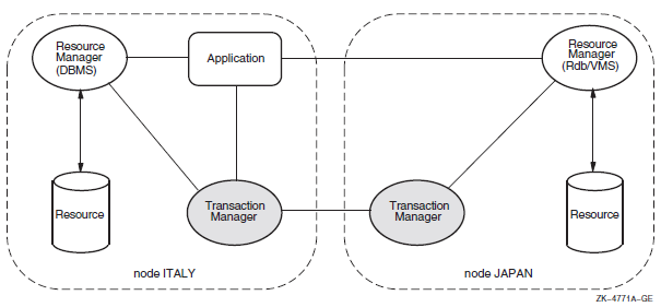 |
14.3. Multiple Branch Application
A transaction may have multiple branches. A separate branch is required for each process that takes part in a transaction, regardless of whether the processes run on the same node or on different nodes of the system.
By making explicit use of the $ADD_BRANCH and $START_BRANCH services. The application can use any suitable communication technique to pass application calls between the processes and nodes of the system. Such communication is not a function of DECdtm.
By calling an RM such as Oracle Rdb that allows resource processing to be requested on another node of the system.
By calling a transaction processing framework such as ACMS that allows processing tasks to be requested on other nodes of the system.
Note that in the last two cases, the RM or TP framework make the necessary branch service calls on behalf of the application. There is no difference in the three cases from the viewpoint of DECdtm.
The top branch of a transaction is created by calling $START_TRANS. A subordinate branch is authorized when an existing branch calls $ADD_BRANCH. This returns a globally unique branch identifier (BID). The application passes the BID and TID with an application-specific request to another process or node of the system. $START_BRANCH is then called on the target node to add a new branch to the transaction. A subordinate branch of a transaction may in turn create further branches.
DECdtm can connect the two parts of the transaction together because $ADD_BRANCH specifies the name of the target node while $START_BRANCH specifies the name of the parent node. Either the two nodes must be in the same OpenVMS Cluster or they must be able to communicate by DECnet. DECdtm operation is more efficient within an OpenVMS Cluster.
Unless DECdtm operation is confined to a single cluster, you must configure each node with the same DECnet node name as its cluster node name.
An application may complete its processing within a branch by calling $END_BRANCH.
On $START_BRANCH, DECdtm checks that the two nodes are able to communicate, but it does not validate that the branch is authorized until $END_BRANCH is called. At that point, an unauthorized branch is aborted without affecting the ability of the authorized branches to commit.
Be careful in situations in which an application attempts to access the same resource from different branches of a transaction. Some RMs can recognize that the branches form part of the same transaction and allow concurrent access to the resource. In that case, just like multiple threads in a process, the application may need to serialize its own operations on the shared resource. Other RMs may lock one branch against another. In that case, the application is likely to deadlock.
Multiple branches in a transaction can serialize their operations on a shared resource within an OpenVMS Cluster using the Lock Manager. Care is needed if two branches outside an OpenVMS Cluster implicitly share a resource, perhaps by each creating a subordinate branch on a third system.
A single process may have multiple branches. For example, a server process may execute parallel operations on behalf of different transactions.
14.3.1. Resource Manager Use of the Branch Services
Strictly defined, an RM provides access to resources on the same process as an AP that has started a transaction or added a branch. However an RM may perform work for a transaction in a different process to the original request. In that case, it must use the branch services to join the transaction in the worker process.
Similarly, an RM such as Oracle Rdb may provide an application interface that allows remote resources to be accessed. In that case, the RM uses the branch services to add a branch on the local node and start a branch on the remote node.
14.3.2. Branch Synchronization
Processing in all branches of a transaction must be complete before calling $END_TRANS.
The call to $START_BRANCH does not specify the DDTM$M_BRANCH_UNSYNCHED flag.
Either $END_BRANCH or $ABORT_TRANS must be called to end the branch.
$END_BRANCH and $END_TRANS calls are not completed with a success status until all synchronized subordinate branches of the transaction have initiated calls to$END_BRANCH and the top branch has initiated a call to $END_TRANS.
$END_TRANS and $END_BRANCH are not completed with an SS$_ABORT status until all synchronized branches on the local node have initiated calls to $END_TRANS, $END_BRANCH, or $ABORT_TRANS.
In other words, when a transaction completes successfully, all synchronized branches complete together. When a transaction aborts, all synchronized branches on a single node complete together, but branches on different nodes complete at different times. Using synchronized branches does not add extra message overhead, because the synchronization events are implicit in the normal DECdtm commitment protocol.
The call to $START_BRANCH specifies the DDTM$M_BRANCH_UNSYNCHED flag.
The branch must not call $END_BRANCH or $ABORT_TRANS. If the transaction is to be aborted, the branch must return an error status to its superior branch.
See Section 14.4, ''Default Transactions'' for a case in which unsynchronized branches are not advised.
14.4. Default Transactions
Set: The process has a default transaction.
Clear: The process does not have a default transaction.
The default transaction is cleared during the processing that occurs when the transaction commits or aborts.
Some operations ($START_TRANS, $START_BRANCH) that set the default transaction of a process will fail if the default transaction of the process was not previously clear. Such operations will update the default transaction without error if it is still set but commit or abort processing that is already in progress.
The default transaction TID is read by the $GET_DEFAULT_TRANS service.
Some RMs check if a default transaction has been started by the application. If there is none, the requested operation is performed as a single atomic operation. Do not use unsynchronized branches with such RMs. The problem is that a transaction might be aborted asynchronously (by another branch) before the branch calls the RM in question. The RM would then perform the operation separately instead of joining the transaction and then receiving an abort notification. This problem cannot occur with a synchronized branch because the default transaction TID is not cleared until $END_BRANCH is called.
14.4.1. Multithreaded Applications
Because the default transaction TID is per-process, not per-thread, it is preferable to use explicit TIDs in multithreaded processes.
However, you must use the default transaction with RMs that do not provide an interface that allows the AP to specify the TID. In this case, use the $SET_DEFAULT_TRANS service to set the appropriate TID in each thread. Take care to serialize each sequence of operations that sets and uses the default transaction.
14.5. Resource Manager Interface
It should implement transactions with the ACID properties on the resources it manages. This is not a precondition for using DECdtm. For example, some RMs compromise on isolation for improved performance; but unless this characteristic is observed, distributed transactions constructed with DECdtm will not have the ACID properties expected by most applications. Section 14.5.6, ''Volatile Resource Manager'' describes where volatile (nondurable) resources are used.
It must be able to participate in the two-phase commit protocol. This means that it must be able to store the state of a transaction on disk in phase 1 and subsequently commit or roll back the changes as requested in phase 2.
It must respond correctly to DECdtm events in the event handler declared by$DECLARE_RM.
On recovery from an RM or node failure it must call DECdtm to determine the state of each transaction that was in phase 2 at the time of the failure. It must then commit or roll back the transaction as determined by DECdtm.
RM instance (RMI) for each process that makes RM-related calls to DECdtm.
RM participant for each transaction in which an RM instance takes part.
The RMI and its RM participants share a single event handler, but each participant may have a different name and context. The name is used to find relevant transactions on recovery. The context is a handle, opaque to DECdtm, which is passed to the event handler and may be used to address RM-specific data.
|
$DECLARE_RM |
Creates an RM instance in the current process. |
|
$JOIN_RM |
Adds an RM participant to a transaction. |
|
$ACK_EVENT |
Acknowledges an event reported to an RMI or RM participant. |
|
$FORGET_RM |
Deletes an RMI from the current process. |
|
$GETDTI |
Gets distributed transaction information. Used to get information about the state of transactions. |
|
$SETDTI |
Sets distributed transaction information. Used to remove RM participants from a transaction. |
14.5.1. Creating RM Instances and Participants
You can create an RMI by calling $DECLARE_RM. This specifies an event handler for the RM in the process and returns the RM_ID that is needed to add participants to transactions.
The RM may call $JOIN_RM on the first operation for a new TID.
The RM may request transaction start events (DDTM$M_EV_TRANS_START). It calls $ACK_EVENT to join every transaction. If an RM participant finds that it takes no part in a transaction, it can vote SS$_FORGET in phase 1.
It must have an RM or facility prefix that is unique to the RM.
Typically it includes an RM-specific name for a group of resources that are recovered as a unit, such as a database or volume.
It may also include an RM log version (see Section 14.5.5, ''Performing Recovery'').
You can design an RM to be used either with or without DECdtm. In the latter case, the RM may perform a single request as a transaction without calling DECdtm. Such RMs must take care when using $GET_DEFAULT_TRANS. A status of SS$_NOCURTID indicates that either no transaction has started, or that a transaction started and then aborted before the RM was called. Therefore, the RM interface must provide some way for an AP to specify whether requests are for DECdtm transactions or not, for example, by using an interface function, or by setting a mode switch with a logical name. Do not decide if a DECdtm transaction is required just by checking $GET_DEFAULT_TRANS for a TID. The RM should return an error (for example, SS$_ABORTED) if the AP requires a DECdtm transaction and there is no current TID.
14.5.2. Reporting an Event Notification
The DECdtm transaction manager reports events to an RMI and the RM participants associated with it using asynchronous system traps (ASTs) executed in the access mode specified in the call $DECLARE_RM that created that RMI.
The identifier of the event report.
A code that describes the event.
The identifier (TID) of the transaction.
The name of the RM participant or RMI.
The context of the RM participant or RMI.
Other data that depend on the type of the event.
|
Symbol |
Description | |
|---|---|---|
|
DDTM$A_TID_PTR |
Address of the identifier (TID) of the transaction. | |
|
DDTM$L_ABORT_ |
Abort reason code (longword). See Appendix B, "OpenVMS Data Types" for a list of possible values. Present only in abort event reports. | |
|
DDTM$L_EVENT_TYPE |
A code that identifies the event (longword).The following table shows the possible values. | |
|
Symbol |
Event | |
|
DDTM$K_ABORT |
Abort | |
|
DDTM$K_COMMIT |
Commit | |
|
DDTM$K_PREPARE |
Prepare | |
|
DDTM$K_ONE_PHASE_COMMIT |
One-phase commit | |
|
DDTM$K_STARTED_DEFAULT |
Default transaction started | |
|
DDTM$K_STARTED_NONDEFAULT |
Nondefault transaction started | |
|
DDTM$L_REPORT_ID |
Event report identifier (unsigned longword). | |
|
DDTM$L_RM_CONTEXT |
The context of the RM participant or RMI to which the event report is being delivered (unsigned longword). | |
|
DDTM$Q_PART_NAME |
The name of the RM participant or RMI to which the event report is being delivered (descriptor). | |
|
DDTM$Q_TX_CLASS |
The transaction class of the transaction (descriptor). | |
Each event report must be acknowledged by calling $ACK_EVENT, specifying the identifier of the report. This acknowledgment need not come from AST context.
The DECdtm transaction manager delivers only one event report at a time to each RM participant. For example, if a prepare event report has been delivered to an RM participant, and the transaction is aborted while the RM participant is doing its prepare processing, then the DECdtm transaction manager does not deliver an abort event report to that RM participant until it has acknowledged the prepare event report by a call to $ACK_EVENT. Note that the DECdtm transaction manager may deliver multiple reports to an RMI.
After acknowledging the event report, the RMI or RM participant should no longer access the event report block.
14.5.3. Responding to Events
The primary requirement of an RM participant is that it should respond to the following DECdtm events by calling $ACK_EVENT.
DDTM$K_PREPARE:
Delivered at the start of phase 1. Normally, the participant saves on disk information needed to commit or abort the transaction, and responds with SS$_PREPARED.
If the participant has not updated any resources during the transaction, it may respond with SS$_FORGET. The participant should then release any locks on its resources. This optimization eliminates an unnecessary commit or abort event.
If the participant had an error while the transaction was active, or is unable to save information to disk, it responds with SS$_VETO. The participant may then abort its transaction and release any locks on its resources.
DDTM$K_ONE_PHASE_COMMIT:
Delivered as an alternative to DDTM$K_PREPARE if there is a single participant and it is in the process that started the transaction.
The participant may commit the transaction and respond with SS$_NORMAL. This optimization eliminates the need for DECdtm to log information and to deliver a commit event.
The participant may respond with SS$_PREPARED to request a regular two-phase commit, or with SS$_VETO to abort the transaction.
DDTM$K_COMMIT:
Delivered when all participants have voted SS$_PREPARED in phase 1.
Normally, the participant commits the transaction and responds with SS$_FORGET. This allows DECdtm to discard the transaction from its log. The participant may then release any locks on its resources.
Alternatively, the participant may respond with SS$_REMEMBER. This is used if the RM encounters an error while committing the transaction. DECdtm retains information about the transaction in its log. The RM must commit the transaction later, as a recovery operation.
DDTM$K_ABORT:
Delivered after $ABORT_TRANS has been called on any node, or when one or more of the participants have responded with SS$_VETO in phase 1.
|
Symbolic Name |
Description |
|---|---|
|
DDTM$_ABORTED |
Application aborted the transaction without giving a reason. |
|
DDTM$_COMM_FAIL |
Transaction aborted because a communications link failed. |
|
DDTM$_INTEGRITY |
Transaction aborted because a resource manager integrity constraint check failed. |
|
DDTM$_LOG_FAIL |
Transaction aborted because an attempt to write to the transaction log failed. |
|
DDTM$_ORPHAN_BRANCH |
Transaction aborted because it had an unauthorized branch. |
|
DDTM$_PART_SERIAL |
Transaction aborted because a resource manager serialization check failed. |
|
DDTM$_PART_TIMEOUT |
Transaction aborted because a resource manager timeout expired. |
|
DDTM$_SEG_FAIL |
Transaction aborted because a process or image terminated. |
|
DDTM$_SERIALIZATION |
Transaction aborted because a serialization check failed. |
|
DDTM$_SYNC_FAIL |
Transaction aborted because a branch had been authorized for it but had not been added to it. |
|
DDTM$_TIMEOUT |
Transaction aborted because its timeout expired. |
|
DDTM$_UNKNOWN |
Transaction aborted for an unknown reason. |
|
DDTM$_VETOED |
Transaction aborted because a resource manager was unable to commit it. |
The participant must abort the transaction and respond with SS$_FORGET. It may then release any locks on its resources.
The previous descriptions suggest that a participant drops locks after calling $ACK_EVENT. It could equally well drop locks immediately before calling $ACK_EVENT.
To ensure isolation between transactions (distributed or otherwise), RMs set locks on all resources that are either read or updated, and observe a two-phase lock protocol. This specifies that a transaction must be divided into a phase when locks may be acquired and a following phase when locks may be released. When any lock is released, no further locks may be acquired. An RM may gain a useful improvement in concurrency by releasing locks on non-updated resources at the end of the active phase, before the transaction is saved on disk.
To obey the two-phase lock protocol for distributed transactions, an RM participant must hold all locks until the start of phase 1. In other words, it must wait for the other participants to complete their active phases of the transaction.
(This is not an absolute requirement by DECdtm. Some RMs allow an application to request reduced isolation between transactions, to get higher concurrency. But if an RM releases locks on non-updated resources before phase 1, distributed transactions constructed with DECdtm will not have the isolation property expected by most applications).
14.5.4. Aborting a Transaction
If an RM detects an error during a transaction, it may return an error status to the AP and allow the AP to decide whether to abort the transaction. For some errors, the RM may decide to veto the transaction when it receives a request to prepare.
However, an RM should not call $ABORT_TRANS itself. A synchronized branch is terminated by $ABORT_TRANS and the decision to terminate the branch should be taken by the AP that started it, not by an RM that it called.
DECdtm has no control over the execution of APs. Therefore, an RM must be prepared to receive and reject application requests for a transaction after calling $ABORT_TRANS, and after DECdtm has signaled the start of phase 1. Under rare conditions, an RM may be asked to vote despite calling $ABORT_TRANS.
14.5.5. Performing Recovery
An RM may fail at any time, or the process or node on which it is running may fail. When the RM is restarted, it must clean up the on-disk state of any transaction that was running at the time of the failure. Typically, this is done by maintaining an RM-specific log of operations. On recovery, you should examine the log to find updates that must be undone (for transactions that are being aborted) or redone (for transactions that are being committed). The RM cannot resume normal operation until it has either reacquired locks for in-progress transactions, or completed or aborted them appropriately.
Logging is a common technique because it performs well, but other methods may be suitable for specific RMs. The key point is that the RM must store sufficient information on disk so that it can abort or complete in-progress transactions following an RM or node restart.
If the RM failed before voting, the RM can assume that the transaction is to be aborted, because the RM never voted to commit the transaction.
If the RM failed after voting, it must determine the outcome of the transaction from DECdtm. This is done using the $GETDTI system service. The RM may query the outcome of a specific transaction, using a TID stored in its own log. Alternatively, it may select all transactions using a prefix of the RM participant names.
$DECLARE_RM returns the ID of the DECdtm log on the local node. The RM should save this ID with its own log, and check the value in a call to $GETDTI. This check will fail if either the wrong TM log or the wrong RM log is used.
The backup sequence number for the RM log may be encoded as a suffix to the RM participant name. On recovery, a $GETDTI scan may be used to check if the DECdtm log records participants with more recent backup sequence numbers than expected. This would indicate that an out-of-date RM log is being recovered.
This check is recommended for RMs that use per-resource logs (rather than a single per-system log), where the risk of an old log being restored is significant.
Two transaction states allow the RM to take action: DTI$K_COMMITTED and DTI$K_ABORTED. The RM may specify that $GETDTI does not complete until a selected transaction has one of these two states.
Alternatively, other states may be returned if the final state of a transaction has not been resolved yet, perhaps because the DECdtm log is unavailable, or DECdtm is still waiting for votes from other RMs or TMs. This allows the RM to continue recovery for other transactions, to take locks for the outstanding unrecovered transactions, and then to resume normal operation.
When an RM has committed or aborted a transaction, it must allow DECdtm to remove the transaction from its log. This is done using the DTI$K_DELETE_RM_NAME function of $SETDTI.
DECdtm implements a presumed-abort optimization. This removes the need for DECdtm to log abort decisions. Therefore, if a query for a TID returns SS$_NOSUCHTID, or the TID is missing from the results of a wildcard query, the RM must assume that the transaction has aborted. There is no need to call $SETDTI in this case.
DECdtm writes the removal of a transaction from its log when the transaction is committed. This means that following a system failure, the DECdtm log may hold commit records for transactions that the RM has forgotten. To prevent such records from eventually filling the log, the RM must occasionally perform recovery by the wildcard scan method, instead of querying specific transactions, and remove its association from any committed transaction that is unknown to the RM.
14.5.6. Volatile Resource Manager
Managing a cache of information that is transactionally consistent, but that can be regenerated from information held by another nonvolatile RM.
Implementing a scratchpad for communication between APs during a series of transactions. Changes to the scratchpad should be undone on transaction abort, but the scratchpad does not need to be reconstructed following a system failure.
Monitoring transaction start, commit, and abort events for performance information or perhaps to clean up volatile state, without managing a real resource.
Declaring an RM as volatile removes the need for DECdtm to log information about RM participants. By definition, the RM does not need to perform recovery after a failure, and does not call $GETDTI.
14.5.7. Modifying the DECdtm Log
On recovery, RMs are expected to wait until each transaction state can be resolved as committed or aborted. During this time, they may be unavailable for new operations, or they may hold locks that block the normal functioning of applications.
When you use DECdtm within an OpenVMS Cluster, any node can access the DECdtm log for recovery, provided that the log is configured on a clustered disk. However, if the log is on a failed node outside the cluster, if communication to the node has failed, or if the disk holding the log has failed, applications may be blocked indefinitely.
In this scenario, you may prefer to intervene manually rather than to tolerate an unavailable system. The DTI$K_MODIFY_STATE function of $SETDTI allows you to change the state of an in-doubt transaction in a DECdtm log. The DTI$K_DELETE_TRANSACTION allows you to remove a transaction from a DECdtm log.
You can make these changes using the Log Manager Control Program (LMCP) REPAIR command rather than calling $SETDTI directly. Intervention of this type is for emergency use and is likely to break the consistency of distributed resources. You may need to perform application-specific updates to resources to restore consistency.
14.5.8. Transaction Class
An AP may specify a transaction class parameter to $START_TRANS or$ADD_BRANCH. This is passed as a string to the RM event handler. The mechanism is provided so that an RM may monitor transaction activity for suitably labeled transactions or branches. Its use is optional.
14.6. Communication Resource Manager Interface
A Communication Resource Manager (CRM) is a special resource manager that acts as a gateway between DECdtm and another TM. Typically, the other TM would be on a system other than an OpenVMS system. You can also write a CRM to link two DECdtm systems using another wise unsupported communication mechanism such TCP/IP.
A CRM in a subordinate branch of a DECdtm transaction is indistinguishable from a normal RM. It responds to DECdtm events normally, except that internally it forwards the events to the remote TM instead of dealing with them directly.
Sets the DDTM$M_COORDINATOR flag to indicate that it is a coordinator on behalf of another TM.
Specifies a new TID. No call to $START_TRANS is required.
Calls $START_BRANCH with the branch ID returned by $JOIN_RM. Specify the CRM instance node as the transaction manager node name (tm_name). No call to $ADD_BRANCH is required.
Uses the $TRANS_EVENT service to prepare, commit, or abort a transaction.
The new TID is derived from the remote TM and must be a universal unique identifier (UUID). If the remote TM does not use UUIDs for its TIDs, the CRM must generate a new TID (using the $CREATE_UID service) and maintain a mapping between remote TM TIDs and DECdtm TIDs. If multiple branches of the same transaction are created, you must use the same DECdtm TID on all branches. Otherwise, RMs may detect spurious lock collisions between branches of the same transaction.
14.7. DECdtm XA Interface (Alpha Only)
The DECdtm XA interface allows a transaction manager (TM) to coordinate transactions performed by a resource manager (RM). For an overview and documentation of the XA interface, see the X/Open CAE Specification document Distributed Transaction Processing: The XA Specification.
The DECdtm XA Veneer allows an XA-compliant RM (such as Oracle) to participate in a global transaction coordinated by DECdtm. As Figure 14.2, ''XA Veneer Example'' shows, you typically use this to combine the XA-compliant RM in a transaction with DECdtm-compliant RMs, such as ACMS, Oracle Rdb, and RMS Journalling.
The XA Veneer is a per-process set of functions that call DECdtm system services on behalf of the RM and map DECdtm events to XA function calls.
The DECdtm XA Gateway allows you to coordinate a DECdtm-compliant RM (such as Oracle Rdb or RMS Journalling) using an XA-compliant transaction processing system, such as BEA TUXEDO. (See Figure 14.3, ''XA Gateway Example'').
The XA Gateway is an XA RM that DECdtm uses to participate in an XA transaction as a subordinate TM. DECdtm passes transaction events to the DECdtm-compliant RMs.
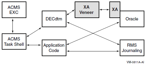
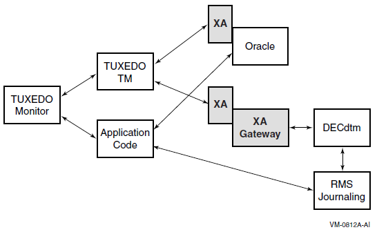
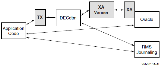
For the convenience of application writers, the DECdtm XA Interface also provides an implementation of the X/Open TX (Transaction Demarcation) interface. This is a simple set of function wrappers for DECdtm system services. (See Figure 14.4, ''TX Wrapper Example'').
Section 14.7.1, ''Using the XA Veneer'' describes how to write an application that uses XA.
Section 14.7.2, ''Nonstandard XA Functions'' describes the DECdtm Veneer extensions.
Section 14.7.3, ''Using the XA Gateway'' describes how to use a DECdtm-compliant resource manager.
Section 14.7.4, ''XA Gateway Control Program (XGCP) Utility'' describes the XA Gateway Control Program (XGCP) utility.
14.7.1. Using the XA Veneer
This section describes how to write an application program that uses an XA-compliant RM in transactions coordinated by DECdtm.
14.7.1.1. Transaction Demarcation
Application programs can use the $START_TRANS, $END_TRANS, and $ABORT_TRANS system services to control transactions.
XA RMs can participate only in the default transaction, because the XA interface model does not allow for explicit transaction IDs passed to RMs by APs.
DECdtm does not support DEC threads or POSIX threads. That is, you can use threading within an application, but the default transaction is managed per process, not per thread.
The XA Veneer does not support the use of $SET_DEFAULT_TRANS to change the current default transaction. That is, an application program may attempt to change the current default transaction, but XA RMs will continue to perform operations in the context of the original default transaction.
The Veneer reports RM xa_start() errors on $START_TRANS by an SS$_ABORT exception. Any RM error also causes the transaction to be aborted and a reason code to be returned from $END_TRANS.
|
XA Return Code |
DECdtm Reason Code |
|---|---|
|
XA_RBCOMMFAIL |
DDTM$_COMM_FAIL |
|
XA_RBDEADLOCK |
DDTM$_PART_SERIAL |
|
XA_RBINTEGRITY |
DDTM$_INTEGRITY |
|
XA_RBTIMEOUT |
DDTM$_PART_TIMEOUT |
|
Other XA_RB* |
DDTM$_VETOED |
|
XAER_DUPID |
Veneer fails |
|
XAER_INVAL |
Veneer fails |
|
XAER_NOTA |
DDTM$_UNKNOWN |
|
XAER_PROTO |
Veneer fails |
|
XAER_RMFAIL |
DDTM$_SEG_FAIL |
|
All others |
DDTM$_UNKNOWN |
The XA Veneer implements the functions ax_open_decdtm() and ax_close_decdtm(). They are identical to the X/Open TX functions tx_open() and tx_close. If ax_open_decdtm() is not called, XA RMs are automatically opened at the start of the first transaction.
Application programs can use the X/Open TX functions instead of DECdtm system services. The TX functions are available in an object module that can be used with the XA Veneer. The tx_begin() function includes an exception handler that maps XA Veneer exceptions to tx_begin() return codes. While the TX wrapper module requires the XA Veneer, the TX functions apply equally to XA and DECdtm RMs.
14.7.1.2. Locking Between Processes
A transaction may access an RM from more than one process. The XA Veneer creates a separate branch of the transaction for each process. This requests the RM to treat each process as a loosely coupled thread as defined by the XA specification. The RM takes locks to isolate access to a resource in one process from access in another process. Consequently, the processes may deadlock against each other if they attempt to access the same resource within a single transaction.
14.7.1.3. Binding to the XA Interface
The address of the XA Switch data structure for the resource manager. See the resource manager documentation for the symbolic name of this switch.
The xa_info text strings for xa_open() and xa_close(). See the resource manager documentation for the specification of these strings.
An optional name for the resource manager instance. (See Section 14.7.1.3.3, ''Resource Manager Instances''). The maximum length of the name is 24 characters, excluding the null terminator.
Static binding is the method implied by the XA standard. The address of the XA Switch and the xa_info text strings are determined at link time.
Dynamic binding requires a run-time call to a nonstandard function. This method gives the application control over the time at which binding and recovery is performed.
You can find definitions of the data structures and constants required to use the XA interface in SYS$LIBRARY:XA.H. This is the "xa.h" as listed in the XA specification. Additional nonstandard functions and flags are defined in SYS$LIBRARY:DDTM_XA.H.
The RM's shareable image or object files.
SYS$LIBRARY:DDTM$XA_RM.OBJ. This object module contains a table of well-known resource managers and initialization code to load the XA Veneer.
SYS$LIBRARY:DDTM$XA.EXE. This shareable image implements the XA Veneer.
You can also link an application against SYS$LIBRARY:DDTM$TX.OBJ to use the TX transaction demarcation interface instead of DECdtm system service calls.
You must install the privileged shareable image SYS$LIBRARY:DDTM$XA_SS.EXE. It provides system services for internal use by the XA interface.
14.7.1.3.1. Static Binding
/* TODO: define or reference your RM switch */
extern struct xa_switch_t SampleSwitch;
/* TODO: define the info strings for xa_open() and xa_close() */
static char RmInfoOpen[] = "SampleInfoOpen";
static char RmInfoClose[] = "SampleInfoClose";
/* TODO: define the RM instance name */
static char RmName[] = "SampleName";
/* put the switch and info addresses in the DDTM$AX_RM psect */
#pragma extern_model strict_refdef "DDTM$AX_RM" pic, shr
void* RmDefSample[] = {&RmSwitchSample,
RmInfoOpen, RmInfoClose, RmName};Change "SampleSwitch" to the symbolic name of the XA switch structure as given in the documentation for your RM.
Change "SampleInfoOpen" and "SampleInfoClose" to xa_info strings as given in the documentation for your RM. Typically, the xa_open string will specify a database name and access information, and the xa_close string may be null.
Change "SampleName" to a resource manager instance name that you choose, as described in Section 14.7.1.3.3, ''Resource Manager Instances''.
.PSECT DDTM$AX_RM,CON,GBL,SHR,NOEXE,WRT,NOCOM,4To make the xa_info strings configurable, the XA Veneer attempts to translate the strings in the SYS$DECDTM_XA_RM logical name table. If the strings cannot be translated, they are passed unchanged to the resource manager.
When you use static binding, the XA Veneer calls xa_recover() either when tx_open() is called or at the start of the first transaction in the image lifetime.
You can use ax_close_decdtm() to close statically bound resource managers.
14.7.1.3.2. Dynamic Binding
An application program can bind additional RMs to the XA Veneer by callingax_bind_decdtm_2(). Dynamic binding requests the XA Veneer to call xa_recover(), which allows recovery to be initiated earlier than with static binding.
Note that ax_open_decdtm() and ax_close_decdtm() have no effect on dynamically bound resource managers.
14.7.1.3.3. Resource Manager Instances
You must specify the resource manager instance name if the resource manager implements multiple instances (or databases) that may be recovered independently. You cannot bind a resource manager into a single process multiple times, unless each binding is for a different named instance.
You must also specify a resource manager instance name if the resource manager instance name in the XA Switch structure is longer than 24 characters. Otherwise, if the resource manager does not support multiple instances, the instance name may be set null, and DECdtm uses the resource manager name in the XA Switch structure as the instance name.
When DECdtm calls xa_recover(), it expects that the resource manager instance returns the complete list of prepared transaction branches for the instance. DECdtm will forget any transactions for the instance that are not returned by xa_recover().
If a process or OpenVMS Cluster node using the XA Veneer fails, DECdtm initiates recovery in any one of the surviving processes in the cluster that are bound to the resource manager instance.
When you choose the instance name, you must set it identically in all processes. It has a maximum size of 24 characters (excluding the null terminator). VSI recommends that the first part of the name is the same as the resource manager name in the XA Switch structure, provided that this is possible within the overall limit of 24 characters.
You can bind a maximum of 1024 resource manager instances in a process.
In this manual, the term "resource manager instance" is used in the same sense as "Oracle Instance" in the Oracle documentation. In the VSI OpenVMS System Services Reference Manual, the DECdtm services descriptions use the same term in a different context and with a different meaning.
14.7.1.3.4. Hints
Check any OpenVMS documentation for your resource manager as well as the generic documentation. For example, the generic documentation for Oracle suggests that you may need to specify an explicit shared library for the Oracle XA RM. However, on OpenVMS no specific action is needed; a reference to the Oracle XA switch structure is sufficient.
To use XA transactions with Oracle 8i on OpenVMS, you must install the Oracle DDBOPT product (Distributed Database Option), and you must enable the Distributed Database Option in the configuration options for the Oracle RDBMS product.
14.7.1.4. Implementation Characteristics
This section provides information for developers of XA-compliant RMs that are to be used with the DECdtm XA Veneer.
The DECdtm XA Veneer does not use some features of the XA interface that must normally be provided by resource managers. This information is provided for the convenience of RM developers, to help them decide if an existing implementation is likely to work with DECdtm. Future implementations of DECdtm XA may make use of these features.
This section also describes possible deviations from the XA standard or common interpretations of the standard.
14.7.1.4.1. Threads
DECdtm does not support DECthreads or POSIX p-threads. That is, the default transaction is managed per process, not per thread. When reading the XA specification, you must regard a thread as equivalent to a process.
The Veneer assumes there is a single default transaction per process and does not attempt to suspend or migrate the association of a transaction branch with a thread or process. Thus, it never sets the TMSUSPEND or TMMIGRATE flags on a call to xa_end(), and never sets TMRESUME on a call to xa_start().
The Veneer never sets the TMJOIN flag on a call to xa_start().
14.7.1.4.2. Heuristic Decision
DECdtm does not support heuristic decisions. If the RM reports a heuristic decision on xa_commit() or xa_rollback(), the Veneer records the decision in a log file. The xa_forget() function is called immediately and the transaction is treated as if it committed or aborted normally.
14.7.1.4.3. Resource Manager Synchronization
The XA Veneer always calls XA functions at non-AST level in user mode. The Veneer never interrupts an XA call with another XA call.
xa_recover()
xa_commit() or xa_rollback() for a transaction listed by xa_recover()
However, such calls are not made while the process has an active transaction, that is, between xa_start() and xa_end(). Therefore, they cannot interrupt the RM while it is executing a call from the application.
TP frameworks, implemented using the earliest version of the DECdtm interface, may run application code in concurrent DECdtm unsynchronized branches. This is not recommended (see the OpenVMS DECdtm Services Reference Manual), partly because the Veneer cannot determine when branch processing ends, and may therefore makexa_end() and xa_rollback() calls asynchronously while an XA RM is processing a call from the application. This occurs only when a transaction is aborted by another DECdtm branch. This problem does not occur with ACMS, because ACMS executes branches serially, not concurrently.
If the version of the TP framework in use does not make a clear statement that synchronized branches are used, and transactions have multiple branches, VSI recommends that applications protect XA RM calls against asynchronous events using the nonstandard functions ax_lock_decdtm() andax_unlock_decdtm(). The Veneer may be locked at the start of branch processing and unlocked at the end, or individual RM calls may be protected by paired lock/unlock calls.
14.7.1.4.4. Asynchronous Operation
This implementation does not use asynchronous operations.
The RM Switch flag TMUSEASYNC is ignored. The TMASYNC flag is never set on calls to the resource manager. The xa_complete() function is never called.
14.7.1.4.5. Resource Manager Switch
An RM can ensure that a future version of the Veneer preserves restrictions and possible nonstandard behavior by setting the nonstandard flag TM_DDTM_V1 in the flags field of the XA Switch data structure.
14.7.1.4.6. Image Termination and Recovery
No XA functions are called directly when an image or process terminates.
The RM is dissociated from any active transaction, and the transaction is aborted.
After an image terminates, a process terminates, or a cluster node fails, DECdtm calls xa_recover() on any one of the surviving processes in the cluster that is bound to the same resource manager instance.
14.7.1.4.7. Transaction Branch Identification
In this implementation, format ID is set to 223585243, gtrid_length is 16 and bqual_length is 36. However, RMs should not make assumptions about the values of these fields.
14.7.1.4.8. Error Handling
In most cases, the return values XAER_INVAL and XAER_PROTO are treated as failures of the XA Veneer. An SS$_BUGCHECK exception is reported. See xa_close() and xa_open() in Section 14.7.1.4.9, ''XA Functions'' for exceptions.
In most cases, XAER_RMERR and XAER_RMFAIL have a common interpretation by the Veneer. The current transaction is aborted, but the RM continues to participate in new transactions. The error return values differ only in that they cause different DECdtm reason codes to be returned to the application. See xa_commit() below for an exception.
14.7.1.4.9. XA Functions
|
ax_reg() |
A return value of TMER_INVAL indicates that either arguments are invalid or the TMREGISTER flag in the resource manager's xa_switch_t data structure was not set. A successful call that returns a NULLXID blocks the AP from starting a new default transaction. Other RMs that register through the same thread also receive a success status with a NULLXID. A call to ax_reg() made while registered fails with XAER_PROTO. TM_JOIN is never returned. A return value of TMER_PROTO may also indicate that xa_reg() was called while there was a current transaction, but called too late to join it. |
|
ax_unreg() |
There is no additional information for this function. |
|
xa_close() |
This function is called for the following reasons:
This function is not called on image exit or process exit. The return value XAER_INVAL is assumed to be an invalid rm_info string, not a Veneer failure. |
|
xa_commit() |
DECdtm does not use the TMNOWAIT flag. The return value XAER_RMERR is treated as a catastrophic failure of the resource manager. The error is logged and the Veneer fails with a SS$_BUGCHECK exception to prevent further processing. The return value XAER_RMFAIL is treated as a less severe error. The error is logged. It is assumed that the resource manager will continue to fail all new transactions with XAER_RMFAIL, but that it may eventually be possible to commit the transaction on recovery. The Veneer attempts to retry xa_commit() when XAER_RETRY is returned. It retries the operation at 10-second intervals for up to 2 minutes. |
|
xa_complete() |
The Veneer never calls this function. |
|
xa_end() |
DECdtm does not use the TMSUSPEND or TMMIGRATE flags. |
|
xa_forget() |
DECdtm does not support heuristic decisions. It calls xa_forget() immediately after an RM reports a heuristic decision. Error return values are recorded in the Veneer error log, but are otherwise ignored. |
|
xa_open() |
Any error return leaves the RM unregistered. The error is recorded in the Veneer error log. The return value XAER_INVAL is assumed to be an invalid rm_info string, not a Veneer failure. |
|
xa_prepare() |
There is no additional information for this function. |
|
xa_recover() |
DECdtm calls xa_recover() for the following
reasons:
DECdtm never sets TMENDRSCAN. Thus, it always performs full scans for prepared transaction branches. DECdtm expects that the RM returns the complete list of prepared transactions started on the current node of the OpenVMS Cluster for an RM instance. Any other transactions that the RM has forgotten will be forgotten by DECdtm. The RM may also return prepared transactions started on other nodes, and these will be resolved. |
|
xa_rollback() |
There is no additional information for this function. |
|
xa_start() |
DECdtm does not use the TMNOWAIT flag. DECdtm does not use the TMJOIN or TMRESUME flags. The return value XAER_DUPID is not expected, because DECdtm calls each resource manager once only for each transaction. It causes the Veneer to report an SS$_BUGCHECK exception. The current DECdtm implementation is unable to return an error from $START_TRANS when the RM returns an error. Instead, the Veneer raises an SS$_ABORT exception, which the application may dismiss. The application should call $END_TRANS or $ABORT_TRANS. The transaction will be aborted in either case. $END_TRANS returns. |
14.7.1.5. Recovery Processes
By default, the XA Veneer calls xa_recover in any process that has bound an RM instance. This is undesirable if the process called to perform recovery runs at low priority or executes an application that may be blocked for link periods with an active transaction. It is especially undesirable if the process uses a resource manager such as Oracle that waits during an active transaction if it finds data that needs recovery.
Define the logical name SYS$DECDTM_XA_RECOVER as "FALSE" or "F" for all processes that may execute transactions. This will prevent xa_recover from being called in those processes. The logical name may be defined group or system wide.
Create a recovery process that binds all XA RMs and has the logical name SYS$DECDTM_XA_RECOVER defined as "TRUE" or "T". This will prevent the process from joining active XA transactions.
Ensure that one or more instances of the recovery process are started before starting any application processes.
#define DESC_INIT_S(p1, p2, p3) \
(p1).dsc$w_length = p2, \
(p1).dsc$b_dtype = DSC$K_DTYPE_T, \
(p1).dsc$b_class = DSC$K_CLASS_S, \
(p1).dsc$a_pointer = (char *) (p3)
main() {
int status;
struct dsc$descriptor dscName;
struct dsc$descriptor dscValue;
/* enable recovery in this process */
DESC_INIT_S(dscName, strlen("SYS$DECDTM_XA_RECOVER"),
"SYS$DECDTM_XA_RECOVER");
DESC_INIT_S(dscValue, 1, "T");
status = lib$set_logical(&dscName, &dscValue);
if ((status & 1) != 1) {
printf("Failed to define logical name, status %d\n", status);
exit(EXIT_FAILURE);
}
/* open XA RMs */
status = ax_open_decdtm();
if (status != TX_OK) {
printf("Error %d on ax_open_decdtm\n", status);
exit(EXIT_FAILURE);
}
/* wait for recovery requests */
while (1)
sys$hiber();
}SYS$LIBRARY:DDTM$XA_RECOVERY.OBJ, or the code shown previously.
An object module binding each RM to the XA Veneer, as described in Section 14.7.1.3.1, ''Static Binding''.
Shareable images or object files for each XA RM.
SYS$LIBRARY:DDTM$XA_RM.OBJ.
SYS$LIBRARY:DDTM$XA.EXE / SHARABLE.
To restore the default behavior (process joins active transactions and may perform recovery) when SYS$DECDTM_XA_RECOVER has been defined as a group or systemwide logical, define SYS$DECDTM_XA_RECOVER as 0 (zero) for the process.
14.7.1.6. Error Logging
The DECdtm XA log file records heuristic decisions and other serious errors that may impact transaction consistency. Typically, these occur on xa_commit() or xa_rollback(), or during recovery. Less serious errors, such as on xa_prepare, are not logged.
To enable logging, define the logical name SYS$DECDTM_XA_LOG to specify a log file. You can define the logical name processwide, groupwide or systemwide. The log file is created automatically and is shared between processes.
tid, bid, time, error_name, rm_name, [reserved], additional_information
|
Error Name |
Meaning |
|---|---|
|
GETDTI |
DECdtm was unable to resolve the transaction state. |
|
HEURCOM |
The transaction branch has been heuristically committed. |
|
HEURHAZ |
The transaction branch may have been heuristically completed. |
|
HEURMIX |
The transaction branch has been heuristically committed and rolled back. |
|
HEURRB |
The transaction branch has been heuristically rolled back. |
|
INVAL |
Invalid arguments were specified to xa_open. Probably the rm_info string is incorrect. |
|
RMERR |
Catastrophic RM failure on xa_commit(). |
|
RMFAIL |
An error occurred that makes the resource manager unavailable. |
|
UNKNOWN |
Unexpected return code from the RM. |
14.7.1.7. Tracing
The XA Veneer includes a trace facility to help investigate problems of interaction between DECdtm and XA resource managers. The trace file shows the sequence of operations. It also shows more detailed error information than that revealed by XA return values.
To enable tracing, define the logical name SYS$DECDTM_XA_TRACE to specify a trace file. You can define the logical name processwide, groupwide or systemwide. The trace file is created automatically and is shared between processes.
All ax_ calls from the application and the resource managers.
All xa_ calls to the resource managers.
XA and OpenVMS error status results returned by the above functions. If no status return is included in the trace, success can be assumed.
DECdtm events and their corresponding acknowledgements.
|
Record Type |
Format |
|---|---|
|
Operation |
time csid pid operation [rmid] |
|
Status |
time csid pid xa_status ["VMS" vms_status] [extra_info] |
14.7.2. Nonstandard XA Functions
|
Function |
Description |
|---|---|
|
ax_bind_decdtm_2() |
Connects an XA resource manager to DECdtm services. |
|
ax_close_decdtm() |
Closes all statically bound resource managers. |
|
ax_lock_decdtm() |
Prevents the XA Veneer from making asynchronous calls to RMs. |
|
ax_open_decdtm() |
Opens all statically bound resource managers. |
|
ax_unbind_decdtm() |
Disconnects a resource manager from DECdtm services. |
|
ax_unlock_decdtm() |
Allows the XA Veneer to call RMs again. |
ax_bind_decdtm_2
ax_bind_decdtm_2 — Makes a connection to DECdtm or starts recovery processing.
Format
#include <xa.h>
int ax_bind_decdtm_2
(xa_switch_t *rmswitch, long flags, int*rmid_out, char *xa_info_open,
char *xa_info_close, char *instance_name)
Parameters
| Input | |
| Rmswitch | The address of the XA Switch data structure. |
| Flags | Control whether ax_bind_decdtm_2() makes a connection to DECdtm, starts recovery processing, or both. See Table 14.4, ''Input Flags for ax_bind_decdtm_2'' for the flags and their meaning. |
| xa_info_open | A null-terminated character string containing contextual information for the resource manager. The maximum length of the string is 256 bytes, including the null terminator. DECdtm does not use the information in xa_info. The Veneer passes this parameter to the resource manager with an xa_open() call. |
| xa_info_close | The same as xa_info_open, except that the Veneer passes this parameter to the resource manager with an xa_close() call. |
| instance_name | Resource manager instance name. The maximum size of the name is 24 characters, excluding the null terminator. |
| Output | |
| rmid_out | The identifier of the resource manager. This value is unique within the process. |
|
Flag |
Meaning |
|---|---|
|
DDTM_M_DECLARE |
Makes a connection between the resource manager and DECdtm. |
|
DDTM_M_RECOVER |
Allows xa_recover() to be called in the current process. |
Description
Call xa_open() to open the resource manager.
Make a connection to DECdtm.
Setting the DDTM_M_DECLARE flag allows XA calls for current transactions to be issued in the local process.
Allow XA recover to be performed in the current process.
Setting the DDTM_M_RECOVER flag enables the local process to call xa_recover() when necessary. At least one process must be enabled to perform recovery. If multiple processes are enabled, the XA Veneer will choose one.
Start recovery.
Before returning from ax_bnd_decdtm_2(), DECdtm calls xa_recover() in one of the processes enabled to perform recovery.
The parameter rmid_out may be specified as NULL if the corresponding value is not required.
Return Values
| XA_OK | Normal execution. |
| XAER_INVAL |
One of the following errors occurred:
|
| XAER_RMERR | A resource manager error occurred when opening the resource. |
| XAER_RMFAIL | A DECdtm error occurred. |
See Also
ax_unbind_decdtm( )
ax_close_decdtm
ax_close_decdtm — Closes all statically bound resource managers.
Format
int ax_close_decdtm (void)
Description
This function is provided to allow an implementation of the X/Open TX specification to implement tx_close().
The function has a nonstandard name to allow a TX implementation other than DECdtm TX to be linked without name conflicts.
This function must not be called from an AST, or with ASTs disabled.
Return Values
| TX_OK | Normal execution. |
| TX_ERROR | One or more of the resource managers encountered a transient error. All resource managers that could be closed are closed. |
| TX_FAIL | One or more of the resource managers encountered a fatal error. |
See Also
ax_open_decdtm( )
ax_lock_decdtm
ax_lock_decdtm — Prevents the XA Veneer from making asynchronous calls to resource managers.
Format
#include <xa.h>
int ax_lock_decdtm (void)
Description
An application program or resource manager may call ax_lock_decdtm() to prevent the XA Veneer from issuing XA calls to resource managers. This ensures that the Veneer cannot make a call to an RM to end and roll back a transaction while the RM is concurrently processing a call from the application.
An application program that calls an XA-compliant RM and that may be run under a TP framework using unsynchronized DECdtm branches should protect all RM calls. This may be done either by locking the Veneer at the start of the transaction, and unlocking it at the end, or by locking the Veneer for each individual RM call.
This function is provided as a temporary measure. Applications do not need to use it if one of the following is true:
Application processing is performed in a single branch.
The application is run under a TP framework that executes branches serially, not concurrently. This is true for ACMS.
The application is run under a TP framework known to use synchronized branches.
The XA Veneer keeps a count of the number of ax_lock_decdtm() calls. The matching number of ax_unlock_decdtm() calls must be made to remove the lock.
Return Values
| TM_OK | Normal execution. |
See Also
ax_unlock_decdtm( )
ax_open_decdtm
ax_open_decdtm — Opens all statically bound resource managers.
Format
int ax_open_decdtm (void)
Description
This function is provided to allow an implementation of the X/Open TX specification to implement tx_open().
The function has a nonstandard name to allow a TX implementation other than DECdtm TX to be linked without name conflicts.
Return Values
| TX_OK | Normal execution. |
| TX_ERROR | One or more of the resource managers encountered a transient error. No resource managers are open. |
| TX_FAIL | One or more of the resource managers encountered a fatal error. |
See Also
ax_close_decdtm( )
ax_unbind_decdtm
ax_unbind_decdtm — Disconnects a resource manager from DECdtm.
Format
#include <xa.h>
int ax_unbind_decdtm (int rmid, long flags)
Parameters
| Input | |
| rmid | The identifier of the resource manager. This must be the same as the rmid_out value returned by DECdtm in the bind_decdtm() call. |
| flags | Must be set to TMNOFLAGS. |
Description
A dynamically bound resource manager calls ax_unbind_decdtm() to disconnect itself from DECdtm. On receiving the ax_unbind_decdtm() call, DECdtm calls xa_close().
This function must not be called from an AST, or with ASTs disabled.
Return Values
| XA_OK | Normal execution. |
| XAER_INVAL | Either the arguments are invalid or the rm_info_close string is invalid. |
| XAER_RMERR | An error occurred when closing the resource. |
| XAER_RMFAIL | A DECdtm error occurred. |
See Also
ax_bind_decdtm_2( )
ax_unlock_decdtm
ax_unlock_decdtm — Allows the XA Veneer to make asynchronous calls to resource managers again.
Format
#include <xa.h>
int ax_unlock_decdtm (void)
Description
This function removes the lock requested by ax_lock_decdtm( ).
Return Values
| TM_OK | Normal execution. |
| TMERR_INVAL | The resource manager has called ax_unlock_decdtm() more often than it has called ax_lock_decdtm(). |
See Also
ax_lock_decdtm( )
14.7.3. Using the XA Gateway
This section describes how to use a resource manager compliant with DECdtm, such as RMS Journaling or Oracle Rdb, with an XA-compliant transaction processing system.
The XA Gateway is configured into each TP process as an XA-compliant resource manager. It handles XA calls from the XA TM and maps these into DECdtm system services. This causes DECdtm to send the appropriate events to any DECdtm compliant Resource Manager (RM) used in a TP process.
The operation of the Gateway is transparent to the RM; DECdtm RMs do not need any modification to be used with the Gateway.
14.7.3.1. Gateway Configuration
The XA Gateway uses a log file to record the mapping between XA transactions and DECdtm transactions. The log file is managed by the Gateway server process DDTM$XG_SERVER.
As of Version 2.1, HP DECdtm/XA Gateway has clusterwide transaction recovery support. Transactions from applications that use a clusterwide DECdtm Gateway Domain Log can be recovered from any single-node failure. Gateway servers running on the remaining cluster nodes can initiate the transaction recovery process on behalf of the failed node.
Use the XGCP utility (described in Section 14.7.4, ''XA Gateway Control Program (XGCP) Utility'' of this manual) to create the Gateway log. The size of the log file depends on the number of concurrently active transactions. Each active transaction requires up to 600 bytes, depending on the size of the transaction ID used by the XA TM. However, the log expands automatically when required.
The log file is created in the directory specified by the logical name SYS$JOURNAL and has a name of the form SYSTEM$name. DDTM$XG_JOURNAL. For optimum performance, move each Gateway log and each DECdtm log to a separate physical device, and define SYS$JOURNAL as a search list for the set of physical devices.
Create a Gateway log with the Gateway name using the XGCP utility.
Specify the gateway name in the xa_open information string when you configure Gateway RM into applications run under the control of an XA TM. (XA RM configuration is described in Section 14.7.3.2, ''XA RM Configuration'').
The first XA application run by the XA TM binds the Gateway name to the local node of the OpenVMS Cluster. It remains bound to that node until the Gateway server is stopped.
You must configure all XA applications run on the local node with the same Gateway name. XA applications using the same name cannot run on other OpenVMS Cluster nodes. Therefore, you should normally define one Gateway name and create one log for each node of an OpenVMS Cluster.
Stop any XA applications on the original node.
Stop the Gateway server on the original node, using the XGCP utility.
Stop any XA applications on the target node.
Stop the Gateway server on the target node, and restart it.
Run the original XA applications on the target node.
Take care to protect against the loss of a Gateway log, perhaps by shadowing the device that holds it. If a new log has to be created, or an out-of-date log is used, transactions that were originally recorded as committed may be incorrectly rolled back. This can cause databases to become inconsistent with each other or inconsistent with reports given to other systems or users.
In general, Gateway logs are not large and it is better never to delete them. Before deleting an unwanted Gateway log, use the DECdtm XGCP utility to check that the Gateway is not still a participant in any prepared transactions. The Gateway participant name is DDTM$XG/name.
Number of concurrent requests processed by the server, in the range 100 to 100,000. This determines the size of the global section DDTM$XG, used for communication with the server, and the quotas required by the server. Specify the parameter by defining the logical name SYS$DECDTM_XG_REQS. Changes to the parameter do not take effect until after the server and all client processes have been stopped.
If this parameter is exceeded in operation, client requests are simply blocked instead of being processed in parallel.
Estimated number of concurrent XA transactions, in the range 1000 to 1,000,000. This determines the size of indexing tables used internally in the server. Specify the parameter by defining the logical name SYS$DECDTM_XA_TRANS. Changes to this parameter do not take effect until after the server has been stopped.
If this parameter is exceeded in operation, server CPU use will increase. However, the effect is unlikely to be noticeable until the parameter is exceeded by a factor of 10 or more.
14.7.3.2. XA RM Configuration
Each XA-compliant transaction manager (TM) defines its own method for including resource managers (RMs). Typically, a configuration file is edited and used as input to build application programs that run under the control of the TM. You may also need to configure and build a separate TM worker process that performs transaction prepare and commit operations.
|
xa_switch_t structure name: |
DDTM$XG_RM_SWITCH |
|
RM name within the RM switch: |
DDTM$XG |
|
Information string for xa_open: |
"SYSTEM$gateway", where gateway is the name of the gateway for the local node of an OpenVMS Cluster. |
|
Information string for xa_close: |
Ignored. May be null. |
|
Sharable image library: |
SYS$LIBRARY:DDTM$XG.EXE |
|
Transaction semantics: | |
|
Protocol optimizations: | |
|
Association migration: |
Not allowed. |
|
Dynamic registration: |
Not used. |
|
Asynchrony: |
Not supported. |
|
Heuristics: |
Not used. |
The Gateway is implemented by the shareable image SYS$LIBRARY:DDTM$XG.EXE.
You must install the privileged sharable image SYS$LIBRARY:DDTM$XG_SS.EXE. It provides system services for internal use by the Gateway and the XGCP utility.
14.7.3.2.1. Hints
The XA switch name is uppercase. Some transaction managers specify exact case compilation when generating references to RM, so you should specify the switch name in uppercase.
Check any OpenVMS documentation for your transaction manager as well as the generic documentation. For example, the generic documentation for Tuxedo uses a colon (:) to separate the resource manager name and XA information strings in a configuration table. However, on OpenVMS, the separator has been changed to a comma (,).
14.7.3.3. Implementation Characteristics
The following sections describe the implementation characteristics of the XA Gateway.
14.7.3.3.1. Default Transaction
The XA Gateway sets the DECdtm default transaction for each XA transaction.
Most DECdtm RMs join the default transaction if an explicit TID is not specified on a call to the RM. If an RM does require an explicit TID, the application can use the $GET_DEFAULT_TRANS system service to read the current default TID.
14.7.3.3.2. Locking Between Processes
DECdtm does not distinguish between loosely coupled and tightly coupled threads, as defined by the XA specification. Instead, each RM makes its own decision whether to allow transaction branches in different processes to share data.
The Gateway allocates a separate DECdtm TID for each branch of an XA global transaction. This allows a branch to be prepared while other branches continue to perform work, as required by the XA specification.
Consequently, DECdtm RMs enforce isolation between the branches of an XA global transaction. This behavior is consistent with the XA specification, but not required by it.
When multiple processes perform work on a single branch within a single node of an OpenVMS Cluster, the gateway allocates a single DECdtm TID for the branch. In principle, this allows the RMs to recognize that work in multiple processes is part of a single transaction, and to use tightly coupled threads. However, it depends on the RM whether this is implemented.
The Gateway does not use the same TID for a single branch of a transaction seen on multiple nodes of an OpenVMS Cluster. However, it is unlikely that any XA TM will use the same branch on different nodes, or that any DECdtm RM is capable of implementing tightly coupled threads between nodes.
14.7.3.3.3. Read-Only Optimization
DECdtm RMs may choose to implement a read-only optimization when a transaction is prepared (see the XA specification). If all DECdtm RMs use the optimization for a given transaction, the Gateway uses the same optimization on the xa_prepare call for the transaction.
14.7.3.3.4. Blocking Conditions
The Gateway is unable to determine if a blocking condition exists or not. Consequently, it always returns XA_RETRY when the TMNOWAIT flag is set.
14.7.3.3.5. XA Return Values
|
DECdtm Reason Code |
XA Return Code |
|---|---|
|
DDTM$_ABORTED |
XA_RBROLLBACK |
|
DDTM$_COMM_FAIL |
XA_RBCOMMFAIL |
|
DDTM$_INTEGRITY |
XA_RBINTEGRITY |
|
DDTM$_PART_SERIAL |
XA_RBDEADLOCK |
|
DDTM$_PART_TIMEOUT |
XA_RBTIMEOUT |
|
DDTM$_SERIALIZATION |
XA_RBDEADLOCK |
|
DDTM$_TIMEOUT |
XA_RBTIMEOUT |
|
DDTM$_VETOED |
XA_RBROLLBACK |
|
All others |
XA_RBOTHER |
|
DECdtm Error Code |
XA Return Code |
|---|---|
|
SS$_ALRCURTID |
XAER_PROTO |
|
SS$_BRANCHSTARTED |
XAER_PROTO |
|
SS$_NOLOG |
XAER_RMFAIL |
|
SS$_TPDISABLED |
XAER_RMFAIL |
|
SS$_WRONGSTATE |
XAER_RBROLLBACK |
|
All others |
XAER_RMERR |
An exception is xa_commit. This function returns XAER_RMFAIL instead of XA_RMERR, because the XA specification states that XA_RMERR indicated a catastrophic failure for this function.
14.7.3.4. Error Logging
The Gateway error log file records errors that prevent it from passing transaction information to DECdtm resource managers. The log file shows more detailed error information than that revealed by XA return values.
To enable error logging, define the logical name SYS$DECDTM_XG_ERROR to specify an error file. You can define the logical name processwide, groupwide, or systemwide. However, you must define it for both TP processes and the Gateway server process. The error file is created automatically and is shared between processes.
|
Record Type |
Format |
|---|---|
|
General |
time csid pid "VMS" vms_status"on" operation |
|
Transaction |
time csid pid "VMS" vms_status"on" operation ", DECdtm TID" tid |
|
TP process |
time csid pid "XA" xa_status"VMS" vms_status "on" operation ", DECdtm TID" tid |
14.7.3.5. Tracing
The Gateway includes a trace facility to help investigate problems of interaction between an XA TM and DECdtm resource managers. The trace file shows the sequence of operations. It also shows more detailed error information than that revealed by XA return values.
To enable tracing, define the logical name SYS$DECDTM_XG_TRACE to specify a trace file. You can define the logical name processwide, groupwide, or systemwide. However, you must define it for TP processes and for the Gateway server process. The trace file is created automatically and is shared between processes.
All xa_ calls to the Gateway.
XA and OpenVMS error status results returned by the XA functions.
Transaction events reported to DECdtm by the Gateway.
|
Record Type |
Format |
|---|---|
|
Operation |
time csid pidoperation [flags] |
|
Status |
time csid pid xa_status ["VMS" vms_status] [extra_info] |
14.7.4. XA Gateway Control Program (XGCP) Utility
This section describes the XA Gateway Control Program (XGCP) utility.
14.7.4.1. XGCP Description
The XGCP utility creates the transaction logs used by the DECdtm XA Gateway. You can also use it to stop and restart the XA Gateway server.
The Gateway allows a resource manager compliant with DECdtm, such as RMS Journaling or Oracle Rdb, to be used with an XA-compliant transaction manager.
14.7.4.2. XGCP Usage Summary
XGCP provides the management interface to the DECdtm XA Gateway.
14.7.4.3. XGCP Description
To invoke XGCP, enter the RUN SYS$SYSTEM:XGCP command at the DCL command prompt. The command has no parameters. At the XGCP> prompt, you can enter any of the XGCP commands described in Section 14.7.4.4, ''XGCP Commands''.
To exit from XGCP, enter the EXIT command at the XGCP> prompt, or press Ctrl/Z.
14.7.4.4. XGCP Commands
|
Command |
Format |
Description | |
|---|---|---|---|
|
CREATE_LOG |
CREATE_LOG |
Creates a new XA Gateway log. This command requires SYSPRV privilege or read/write access to the SYS$JOURNAL directory. Create a gateway log with the name
SYS$JOURNAL:SYSTEM$ Create a separate log for each node of an OpenVMS Cluster. The log file is automatically expanded when necessary. | |
|
Qualifier |
Description | ||
|
|
Specifies a gateway name of up to 15 characters. This qualifier is required. | ||
|
|
Specifies the initial size of the log, in blocks. If you omit this qualifier, the log is created with an initial size of 242 blocks. | ||
|
EXIT |
EXIT |
Exits XGCP | |
|
START_SERVER |
START_SERVER |
Starts the XA Gateway server. Requires the IMPERSONATE privilege. This command executes the DCL command file SYS$STARTUP:DDTM$XG_STARTUP.COM. The server process is called DDTM$XG_SERVER. | |
|
STOP_SERVER |
STOP_SERVER |
Stops the XA Gateway server. Requires OPER privilege. | |
14.8. Program Examples Using DECdtm
The following sections present Fortran, C, and BLISS examples of applications using DECdtm.
14.8.1. Fortran Program Example
The following is a sample Fortran application that uses DECdtm system services. (See SYS$EXAMPLES:DECDTM$EXAMPLE1 below).
Increments the counter by 1.
Calls SYS$START_TRANSW to start a new transaction.
Writes the counter value to the two files.
Either calls SYS$END_TRANSW to attempt to commit the transaction, or calls SYS$ABORT_TRANSW to abort the transaction.
The application repeats these steps until either an error occurs or the user requests an interrupt. Because DECdtm services are used, the two files will always be in step with each other. If DECdtm services were not used, one file could have been updated while the other was not. This would result in the files being out of step.
C C This program assumes that the files DECDTM$EXAMPLE1.FILE_1 and C DECDTM$EXAMPLE1.FILE_2 are created and marked for recovery unit C journaling using the command file SYS$EXAMPLES:DECDTM$EXAMPLE1.COM C C To run this example, enter the following: C $ FORTRAN SYS$EXAMPLES:DECDTM$EXAMPLE1 C $ LINK DECDTM$EXAMPLE1 C $ @SYS$EXAMPLES:DECDTM$EXAMPLE1 C $ RUN DECDTM$EXAMPLE1 C C C SYS$EXAMPLES also contains an example C application, DECDTM$EXAMPLE2.C C The C application performs the same operations as this Fortran example. C IMPLICIT NONE INCLUDE '($SSDEF)' INCLUDE '($FORIOSDEF)' CHARACTER*12 STRING INTEGER*2 IOSB(4) INTEGER*4 STATUS,COUNT,TID(4) INTEGER*4 SYS$START_TRANSW,SYS$END_TRANSW,SYS$ABORT_TRANSW EXTERNAL SYS$START_TRANSW,SYS$END_TRANSW,SYS$ABORT_TRANSW EXTERNAL JOURNAL_OPEN C C Open the two files C
| The application opens DECDTM$EXAMPLE1.FILE_1 and DECDTM$EXAMPLE1.FILE_2 for writing. It then zeroes the variable COUNT and enters an infinite loop. |
| The application increments the count by one and converts it to an ASCII string. |
| The application calls SYS$START_TRANSW to start a transaction. The application checks the immediate return status and service completion status to see whether they signify an error. |
| The application attempts to write the string to the two files. If it cannot, the application aborts the transaction. Because the files are OpenVMS RMS journalled files, the default transaction is assumed. |
| The application calls SYS$END_TRANSW to attempt to commit the transaction. It checks the immediate return status and service completion status to see whether they signify an error. If they do, the application reports the error and exits. If there are no errors, the transaction is committed and the application continues with the loop. |
| If either of the two files cannot be updated, the application calls SYS$ABORT_TRANSW to abort the transaction. It checks the immediate return status and service completion status to see whether they signify an error. If they do, the application reports the error and exits. |
14.8.2. C Program Examples
The C examples are taken from the Transactional Array of Strings (TAOS) sample resource manager. It implements a file holding an array of string values that are updated by transactions. The sample is too large to reproduce in this manual, but is available in SYS$EXAMPLES.
taos: This holds global information about the string array, including the rm_id. It is passed an opaque handle to applications using TAOS.
part: This is created when TAOS participates in a transaction. It holds the TID and is specified as the rm_context to $JOIN_RM. The taos structure holds a list of part structures indexed by TID.
res: This is created when a TAOS resource (a string) is referenced or updated in a transaction. The part structure holds a list of res structures indexed by array number.
#include <ddtmdef.h>
#include <ddtmmsgdef.h>
#include <descrip.h>
#include <dtidef.h>
#include <iosbdef.h>
#include <ssdef.h>
#include <starlet.h>
#include <stsdef.h>14.8.2.1. $DECLARE_RMW
struct taos {
uint tmLogId[4]; /* transaction manager log ID */
uint efn; /* event flag for TAOS operations */
uint rmId; /* resource manager ID */
struct dsc$descriptor_s resNameDsc; /* resource name */
char resName[24]; /* "TAOS____" + array ID */
};
int taos_Open(...) {
int status;
IOSB iosb;
BOOL declaredRm = FALSE;
status = sys$declare_rmw(pTaos->efn, 0, &iosb, NULL, 0, &pTaos->rmId,
&HandleEvent, &pTaos->resNameDsc, NULL,
0, pTaos->tmLogId, 0);
if (SUCCESS(status))
status = iosb.iosb$w_status;
if (SUCCESS(status))
declaredRm = TRUE;
return status;
}14.8.2.2. $GET_DEFAULT_TRANS and $JOIN_RMW
This example shows how to check for a default transaction, and join the resource manager to a transaction.
int taos_Write(.., uint pTid[4]) {
int status;
/* get transaction ID */
if (pTid != NULL)
CopyUid(tid, pTid);
else {
status = sys$get_default_trans(tid);
if (FAILURE(status))
return status;
}
/* if this is a new transaction, join it */
if (GetParticipantData(pTaos, tid, &pPart)) {
status = sys$join_rmw(pTaos->efn, 0, &iosb, NULL, 0,
pTaos->rmId, tid, NULL, pPart);
if (SUCCESS(status))
status = iosb.iosb$w_status;
if (FAILURE(status))
return status;
}
} 14.8.2.3. Event Handler and $ACK_EVENT
static int HandleEvent(DDTM$R_REPORTDEF *pReport) { struct taos *pTaos; switch (pReport->ddtm$l_event_type) { case DDTM$K_PREPARE: Prepare(pReport); break; case DDTM$K_ABORT: Abort(pReport); break; case DDTM$K_ONE_PHASE_COMMIT: OnePhaseCommit(pReport); break; case DDTM$K_COMMIT: Commit(pReport); break; return SS$_NORMAL; } /* Abort the transaction */ static void Abort(DDTM$R_REPORTDEF *pReport) { struct part *pPart = (struct part *) pReport->ddtm$l_rm_context; /* Undo the transaction here, using the list of resources * attached to the part structure. */ /* DECdtm can forget the transaction */ sys$ack_event(0, pReport->ddtm$l_report_id, SS$_FORGET); } /* Prepare transaction (phase 1 commit) */ static void Prepare(DDTM$R_REPORTDEF *pReport) { int status = SS$_NORMAL; BOOL updates = FALSE; /* Save updates on disk, using the list of resources attached to * the part structure. Set updates if there are any. Set status * on error; /* vote on transaction */ if (FAILURE(status)) status = SS$_VETO; /* can't prepare, so abort tran */ else if (!updates) status = SS$_FORGET; /* read-only transaction */ else status = SS$_PREPARED; /* ready to commit or abort */ sys$ack_event(0, pReport->ddtm$l_report_id, status); } /* Commit transaction (phase 2) */ static void Commit(DDTM$R_REPORTDEF *pReport) { int status = SS$_NORMAL; /* Make updates permanent and visible to other users here. * Set status on error. */ if (SUCCESS(status)) status = SS$_FORGET; /* DECdtm can forget transaction */ else { /* We can't commit the transaction yet. We must ask DECdtm to * remember the transaction, and we must terminate operations * until a successful recovery is performed. */ pTaos->status = status; status = SS$_REMEMBER; } /* acknowledge event */ sys$ack_event(0, pReport->ddtm$l_report_id, status); } /* Prepare and commit transaction in a single phase */ static void OnePhaseCommit(DDTM$R_REPORTDEF *pReport) { int status = SS$_NORMAL; /* Combine operations from Prepare() and Commit() here. * Set status on error. */ /* report outcome to DECdtm */ if (FAILURE(status)) status = SS$_VETO; /* aborted */ else status = SS$_NORMAL; /* committed */ status = SS$_NORMAL; /* committed */ sys$ack_event(0, pReport->ddtm$l_report_id, status); }
14.8.2.4. $GETDTI and $SETDTI
/* Recover the state of a prepared resource after a failure */
RecoverString(...) {
int status;
IOSB iosb;
uint context = 0; /* context from $GETDTI */
int retlen;
Int state; /* transaction state */
DTIRECDEF dti;
ITMLST3_DECL (search, 1);
ITMLST3_ITEM (search, 0, DTI$_SEARCH_RESOLVED_STATE,
DTI$S_TRANSACTION_INFORMATION, &dti, 0);
DTI$S_TRANSACTION_INFORMATION, &dti, 0);
ITMLST3_END (search);
ITMLST3_DECL (result, 1);
ITMLST3_ITEM (result, 0, DTI$_TRANSACTION_INFORMATION,
DTI$S_TRANSACTION_INFORMATION, &dti, &retlen);
ITMLST3_END (result);
/* get final state of transaction */
dti.dti$b_part_name_len = 0; /* no RM name specified */
CopyUid((uint *) dti.dti$t_tid, pTaos->stringBuf.tid);
status = sys$getdtiw(pTaos->efn, DDTM$M_FULL_STATE, &iosb, NULL, 0,
pTaos->tmLogId, &context, &search, &result);
if (SUCCESS(status))
status = iosb.iosb$w_status;
if (SUCCESS(status))
state = dti.dti$b_state;
/* treat forgotten TID as presumed abort */
if (status == SS$_NOSUCHTID) {
state = DTI$K_ABORTED;
status = SS$_NORMAL;
}
if (SUCCESS(status)) {
switch (state) {
case DTI$K_COMMITTED:
/* Make update permanent and visible here.
* Set status on error. */
break;
case DTI$K_ABORTED:
/* Undo the update here. Set status on error. */
break;
}
}
if (SUCCESS(status)) {
/* allow DECdtm to remove this RM from the transaction */
status = sys$setdtiw(pTaos->efn, 0, &iosb, NULL, 0, &context
DTI$K_DELETE_RM_NAME, &result);
}
} 14.8.3. BLISS Program Example
The following BLISS program demonstrates how a simple resource manager may perform recovery following a system failure. In the example, a $GETDTI is executed on behalf of a remote node (MYNODE) specifying a transaction identifier, named resource manager, participant log identifier and transaction manager log identifier.
MODULE RECOVER_TRANSACTION (MAIN=MAIN)=
BEGIN
LIBRARY'SYS$LIBRARY:STARLET';
FORWARD ROUTINE
MAIN,
AST_COMPLETION_ROUTINE : NOVALUE;
ROUTINE MAIN =
BEGIN
OWN
STATUS
: LONG UNSIGNED,
IOSB
: VECTOR [4,WORD],
SEARCH_CONTEXT
: LONG UNSIGNED
INITIAL (0),
PART_LOG_ID
: $BBLOCK [DTI$S_PART_LOG_ID]
INITIAL (REP DTI$S_PART_LOG_ID OF BYTE (0)),
TM_LOG_ID
: $BBLOCK [DTI$S_PART_LOG_ID]
INITIAL (REP DTI$S_PART_LOG_ID OF BYTE (0)),
TID
: $BBLOCK [DTI$S_TID]
INITIAL (REP DTI$S_TID OF BYTE (0)),
SEARCH_LIST
: $ITMLST_DECL (ITEMS=2),
ITEM_LIST
: $ITMLST_DECL (ITEMS=1),
TRANS_INFO
: $BBLOCK [DTI$S_TRANSACTION_INFORMATION];
BIND
SEARCH_NODE_NAME = UPLIT (%ASCII'MYNODE'),
RESOURCE_MANAGER = UPLIT (%ASCII'FRED');
LITERAL
SEARCH_NODE_NAME_LENGTH = %CHARCOUNT ('MYNODE'),
RESOURCE_MANAGER_LENGTH = %CHARCOUNT ('FRED');
! Resource manager opens recovery log and reads first resolved
! recovery record. The information in the recovery record
! should contain the transaction identifier, resource manager
! log identifier and transaction manager log identifier. This
! information is written into the transaction information
! record.
CH$MOVE (DTI$S_TID,
TID,
TRANS_INFO [DTI$T_TID]);
CH$MOVE (DTI$S_PART_LOG_ID,
PART_LOG_ID,
TRANS_INFO [DTI$T_PART_LOG_ID]);
CH$MOVE (RESOURCE_MANAGER_LENGTH,
.RESOURCE_MANAGER,
TRANS_INFO [DTI$T_PART_NAME]);
TRANS_INFO [DTI$B_PART_NAME_LEN] = RESOURCE_MANAGER_LENGTH;
! The search item list is initialized with a node
! name and transaction information record.
$ITMLST_INIT (ITMLST=SEARCH_LIST,
(ITMCOD=DTI$_SEARCH_AS_NODE,
BUFADR=.SEARCH_NODE_NAME,
BUFSIZ=SEARCH_NODE_NAME_LENGTH),
(ITMCOD=DTI$_SEARCH_RESOLVED_STATE,
BUFADR=TRANS_INFO,
BUFSIZ=DTI$S_TRANSACTION_INFORMATION));
! The item list is initialized to return a transaction
! information record containing the resolved state of the
! transaction.
! transaction.
$ITMLST_INIT (ITMLST=ITEM_LIST,
(ITMCOD=DTI$_TRANSACTION_INFORMATION,
BUFADR=TRANS_INFO,
BUFSIZ=DTI$S_TRANSACTION_INFORMATION));
! A $GETDTI is now performed to return the state of the
! transaction and the node name.
STATUS = $GETDTIW (EFN=10,
FLAGS=DDTM$M_FULL_STATE,
IOSB=IOSB,
ASTADR=AST_COMPLETION_ROUTINE,
ASTPRM=0,
CONTXT=SEARCH_CONTEXT,
LOG_ID=TM_LOG_ID,
SEARCH=SEARCH_LIST,
ITMLST=ITEM_LIST);
! If the transaction was committed then perform resource manager
! recovery and then delete the resource manager from the
! transaction.
IF .TRANS_INFO [DTI$B_STATE] EQLU DTI$K_COMMITTED THEN
STATUS = $SETDTIW (EFN=10,
FLAGS=0,
IOSB=IOSB,
ASTADR=AST_COMPLETION_ROUTINE,
ASTPRM=0,
CONTXT=SEARCH_CONTEXT,
FUNC=DTI$K_DELETE_RM_NAME,
ITMLST=ITEM_LIST);
RETURN .STATUS
END;
ROUTINE AST_COMPLETION_ROUTINE (ASTPRM : LONG UNSIGNED) : NOVALUE =
BEGIN
RETURN;
END;
END
ELUDOMChapter 15. Creating User-Written System Services
This chapter describes how to create user-written system services.
15.1. Overview
Your application may contain certain routines that perform privileged functions, called user-written system services. To create these routines, put them in a privileged shareable image. User-mode routines in other modules can call the routines in the privileged shareable image to perform functions in a more privileged mode.
Create the source file. The source file for a privileged shareable image contains the routines that perform privileged functions. In addition, because user-written system services are called using the system service dispatcher, you must include a privileged library vector (PLV) in your shareable image. A PLV is an operating-system-defined data structure that communicates the location of the privileged routines to the operating system.
On VAX systems, the PLV contains the addresses of dispatch routines for each access mode used in the image. You must write these dispatch routines and include them in your shareable image. Section 15.3.1, ''Creating User-Written Dispatch Routines on VAX Systems'' provides more information.
On Alpha and IA-64 systems, you list the names of the privileged routines in the PLV, sorted by access mode. You do not need to create dispatch routines; the image activator creates them for you automatically.
Section 15.2, ''Writing a Privileged Routine (User-Written System Service)'' provides guidelines for creating privileged routines.
Compile or assemble the source file.
- Create the shareable image. You create a privileged shareable image as you would any other shareable image: by specifying the /SHAREABLE qualifier to the LINK command. Note, however, that creating privileged shareable images has some additional requirements. The following list summarizes these requirements. See the VSI OpenVMS Linker Utility Manual for additional information about linker qualifiers and options.
Declare the privileged routine entry points as universal symbols. Privileged shareable images use the same mechanisms to declare universal symbols as other shareable images: transfer vectors on VAX and symbol vectors on Alpha and IA-64 systems. However, because calls to user-written system services must be vectored through the system service dispatcher, you must use extensions to these mechanisms for privileged shareable images. Section 15.3.3, ''Declaring Privileged Routines as Universal Symbols Using Transfer Vectors on VAX Systems'' describes how to declare a universal symbol in a VAX privileged shareable image. Section 15.4.2, ''Declaring Privileged Routines as Universal Symbols Using Symbol Vectors on Alpha and IA-64 systems''describes how to declare a universal symbol in an Alpha and IA-64 system privileged shareable image.
Prevent the linker from processing the system default shareable image library, SYS$LIBRARY:IMAGELIB.OLB, by specifying the /NOSYSSHR linker qualifier. Otherwise, the linker processes this library by default.
Protect the shareable image from user-mode access by specifying the /PROTECT linker qualifier. If you want to protect only certain portions of the shareable image, instead of the entire image, use the PROTECT= linker option.
Set the VEC attribute of the program section containing the PLV by using the PSECT_ATTR= linker option. Modules written in MACRO can specify this attribute in the .PSECT directive. The PLV must appear in a program section with the VEC attribute set.
Set the shareable image identification numbers using the GSMATCH= option.
If your privileged application requires that you link against the system executive, see the VSI OpenVMS Linker Utility Manual for more information.
- Install the privileged shareable image as a protected permanent global section. Privileged shareable images must be installed to be available to nonprivileged programs. The following procedure is recommended:
Move the privileged shareable image to a protected directory, such as SYS$SHARE.
- Invoke the Install utility, specifying the /PROTECT, /OPEN, and /SHARED qualifiers. You can also specify the /HEADER_RESIDENT qualifier. The following entry could be used to install a user-written system service whose image name is MY_PRIV_SHARE:
$ INSTALL INSTALL> ADD SYS$SHARE:MY_PRIV_SHARE/PROTECT/OPEN/SHARED/HEADER_RES
To use a privileged shareable image, you include it in a link operation as you would any other shareable image: specifying the shareable image in a linker options file with the /SHAREABLE qualifier appended to the file specification to identify it as a shareable image.
15.2. Writing a Privileged Routine (User-Written System Service)
PRVMSK: .LONG <1@PRV$V_OPER>!<1@PRV$V_PHY_IO> ;OPER and PHY_IO .LONG 0 ;quadword mask required. No bits set in ;high-order longword for these privileges. . . . $SETPRV_S ENBFLG=#1,- ;1=enable, 0=disable PRVADR=PRVMSK ;Identifies the privileges
Keep privileges off, and turn them on only when necessary.
Make sure privileges are off on all exit paths. When you perform a task for the user, operate in user mode whenever possible and operate at all times with the user's privileges, identity, and so on. Make sure that operating in an inner mode does not give you any special privileges with respect to the operation being performed. Resume a privileged state only when you are about to resume operation on your own behalf.
If user input can affect an operation executed with privilege, you have to carefully validate the input. Never pass user parameters directly to an operation executed in an inner mode or with privilege. When designing your program, keep in mind that the inner modes implicitly provide a user with the system privileges SETPRV, CMKRNL, SYSNAM, and SYSLCK. (See the VSI OpenVMS Guide to System Security for descriptions).
As a protected image, your program does not have the entire operating system programming environment at its disposal. Unless a module has the prefix SYS$ or EXE$, you must avoid calling it from an inner mode. In particular, do not call LIB$GET_VM or LIB$RET_VM from an inner mode. You can call OpenVMS RMS routines from executive mode but not from kernel mode.
On VAX systems, Version 5.4 or later of the operating system, any OpenVMS RMS files that were opened with privilege from an inner mode can be left open during user execution; however, this is not acceptable on earlier versions of the operating system.
Never make subroutine calls to other shareable images from kernel or executive mode.
When a protected subsystem opens a file on its own behalf, it should specify executive-mode logical names only by naming executive mode explicitly in the FAB$V_LNM_MODE subfield of the file access block (FAB). This prevents a user's logical name from redirecting a file specification.
On VAX systems, refer to SYS$EXAMPLES:USSDISP.MAR and USSTEST.MAR for listings of modules in a user-written system service and of a module that calls the user-written system service.
On Alpha and IA-64 systems, for C examples refer to SYS$EXAMPLES:UWSS.C and SYS$EXAMPLES:UWSS_TEST.C.
15.3. Creating a Privileged Shareable Image (VAX Only)
On VAX systems, you must create dispatch routines that transfer control to the privileged routines in your shareable image. You then put the addresses of these dispatch routines in a privileged library vector (PLV). Section 15.3.1, ''Creating User-Written Dispatch Routines on VAX Systems'' describes how to create a dispatch routine. Section 15.3.2, ''Creating a PLV on VAX Systems'' describes how to create a PLV.
15.3.1. Creating User-Written Dispatch Routines on VAX Systems
On VAX systems, you must create kernel-mode and executive-mode dispatching routines that transfer control to the routine entry points. You must supply one dispatch routine for all your kernel mode routines and a separate routine for all the executive mode routines. The dispatcher is usually written using the CASE construct, with each routine identified by a code number. Make sure that the identification code you use in the dispatch routine and the code specified in the transfer vector identify the same routine.
The image activator, when it activates a privileged shareable image, obtains the addresses of the dispatch routines from the PLV and stores these addresses at a location known to the system service dispatcher. When a call to a privileged routine is initiated by a CHME or CHMK instruction, the system service dispatcher attempts to match the code number with a system service code. If there is no match, it transfers control to the location where the image activator has stored the address of your dispatch routines.
Note
Users of your privileged shareable image must specify the same code number to identify a privileged routine as you used to identify it in the dispatch routine. Users specify the code number in their CHMK or CHME instruction. See Section 15.3.3, ''Declaring Privileged Routines as Universal Symbols Using Transfer Vectors on VAX Systems'' for information about transfer vectors.
In your source file, a dispatch routine must precede the routines that implement the user-written system service.
KERNEL_DISPATCH:: ; Entry to dispatcher
MOVAB W^-KCODE_BASE(R0),R1 ; Normalize dispatch code value
BLSS KNOTME ; Branch if code value too low
CMPW R1,#KERNEL_COUNTER ; Check high limit
BGEQU KNOTME ; Branch if out of range
;
; The dispatch code has now been verified as being handled by this dispatcher,
; now the argument list will be probed and the required number of arguments
; verified.
;
MOVZBL W^KERNEL_NARG[R1],R1 ; Get required argument count
MOVAL @#4[R1],R1 ; Compute byte count including argcount
IFNORD R1,(AP),KACCVIO ; Branch if arglist not readable
CMPB (AP),W^<KERNEL_NARG-KCODE_BASE>[R0] ; Check for required number
BLSSU KINSFARG ; of arguments
MOVL FP,SP ; Reset stack for service routine
CASEW R0,- ; Case on change mode
.
.
.15.3.2. Creating a PLV on VAX Systems
On VAX systems, a call to a privileged routine goes to the transfer vector that executes a change mode instruction (CHMx) specifying the identification code of the privileged routine as the operand to the instruction. The operating system routes the change mode instruction to the system service dispatch routine, which attempts to locate the system service with the code specified. Because the code is a negative number, the system service dispatcher drops through its list of known services and transfers control to a user-written dispatch routine, if any have been specified.
The image activator has already placed at this location the address of whatever user-written dispatch routines it found in the privileged shareable image's PLV when it activated the PLV. The dispatch routine transfers control to the routine in the shareable image identified by the code. (You must ensure that the code used in the transfer vector and the code specified in the dispatch routine both identify the same routine). Figure 15.1, ''Flow of Control Accessing a Privileged Routine on VAX Systems'' illustrates this flow of control.
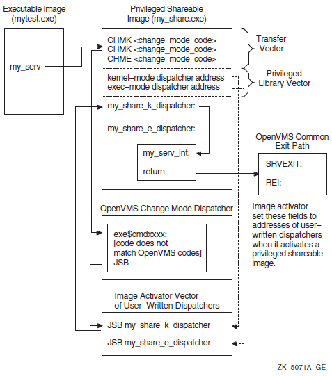
Figure 15.2, ''Components of the Privileged Library Vector on VAX Systems'' shows the components of the PLV in VAX shareable images.
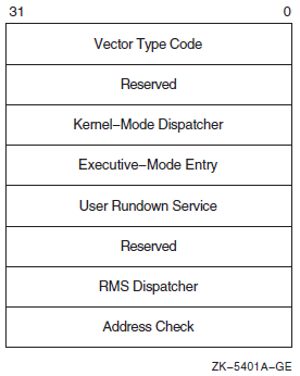
|
Component |
Symbol |
Description |
|---|---|---|
|
Vector type code |
PLV$L_TYPE |
Identifies the type of vector. For PLVs, you must specify the symbolic constant defined by the operating system, PLV$C_TYP_CMOD, which identifies a privileged library vector. |
|
Kernel-mode dispatcher |
PLV$L_KERNEL |
Contains the address of the user-supplied kernel-mode dispatching routine if your privileged library contains routines that run in kernel mode. The address is expressed as an offset relative to the start of the data structure (self-relative pointer). A value of 0 indicates that a kernel-mode dispatcher does not exist. |
|
Executive-mode dispatcher |
PLV$L_EXEC |
Contains the address of the user-supplied executive-mode dispatching routine if your privileged library contains routines that run in executive mode. The address is expressed as an offset relative to the start of the data structure (self-relative pointer). A value of 0 indicates that a kernel-mode dispatcher does not exist. |
|
User-supplied rundown routine |
PLV$L_USRUNDWN |
Contains the address of a user-supplied rundown routine that performs image-specific cleanup and resource deallocation if your privileged library contains such a routine. When the image linked against the user-written system service is run down by the system, this run-time routine is invoked. Unlike exit handlers, the routine is always called when a process or image exits. (The image rundown code calls this routine with a JSB instruction; it returns with an RSB instruction called in kernel mode at IPL 0). |
|
RMS dispatcher |
PLV$L_RMS |
Contains the address of a user-supplied dispatcher for OpenVMS RMS services. A value of 0 indicates that a user-supplied OpenVMS RMS dispatcher does not exist. Only one user-written system service should specify the OpenVMS RMS vector, because only the last value is used. This field is intended for use only for OpenVMS. |
|
Address check |
PLV$L_CHECK |
Contains a value to verify that a user-written system service that is not position independent is located at the proper virtual address. If the image is position independent, this field should contain a zero. If the image is not position independent, this field should contain its own address. |
.PAGE
$PLVDEF ; Define PLV fields
.SBTTL Change Mode Dispatcher Vector Block
.PSECT USER_SERVICES,PAGE,VEC,PIC,NOWRT,EXE
.LONG PLV$C_TYP_CMOD ; Set type of vector to change mode
.LONG 0 ; Reserved
.LONG KERNEL_DISPATCH-. ; Offset to kernel mode dispatcher
.LONG EXEC_DISPATCH-. ; Offset to executive mode dispatcher
.LONG USER_RUNDOWN-. ; Offset to user rundown service
.LONG 0 ; Reserved.
.LONG 0 ; No RMS dispatcher
.LONG 0 ; Address check - PIC image
| The sample program sets the VEC attribute of the program section containing the PLV. |
| Values are assigned to each field of the PLV. |
15.3.3. Declaring Privileged Routines as Universal Symbols Using Transfer Vectors on VAX Systems
.TRANSFER my_serv .MASK my_serv CHMK <code_number> RET
Because the OpenVMS system services codes are all positive numbers and because the call to a privileged routine is initially handled by the system service dispatcher, you should assign negative code numbers to identify your privileged routines so they do not conflict with system services identification codes.
15.4. Creating a User-Written System Service (Alpha and I64 Only)
On Alpha and IA-64 systems, in addition to the routines that perform privileged functions, you must also include a PLV in your source file. However, on Alpha and IA-64 systems, you list the privileged routines by name in the PLV. You do not need to create a dispatch routine that transfers control to the routine; the routine is identified by a special code.
15.4.1. Creating a PLV on Alpha and IA-64 systems
On Alpha and IA-64 systems, the PLV contains a list of the actual addresses of the privileged routines. The image activator creates the dispatch routines. Figure 15.3, ''Linkage for a Privileged Routine After Image Activation'' illustrates the linkage for a privileged routine on Alpha and IA-64 systems.
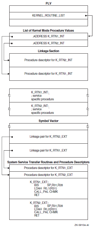
|
Component |
Symbol |
Description |
|---|---|---|
|
Vector type code |
PLV$L_TYPE |
Identifies the type of vector. You must specify the symbolic constant, PLV$C_TYP_CMOD, to identify a privileged library vector. |
|
System version number |
PLV$L_VERSION |
Specifies the system version number (unused). |
|
Kernel-mode routine count |
PLV$L_KERNEL_ROUTINE_ |
Specifies the number of user-supplied kernel-mode routines listed in the kernel-mode routine list. The address of this list is specified in PLV$PS_KERNEL_ROUTINE_LIST. |
|
Executive-mode routine count |
PLV$L_EXEC_ROUTINE_ |
Specifies the number of user-supplied executive-mode routines listed in the executive-mode routine list. The address of this list is specified in PLV$PS_EXEC_ROUTINE_LIST. |
|
Kernel-mode routine list |
PLV$PS_KERNEL_ROUTINE_ |
Specifies the address of a list of user-supplied kernel-mode routines. |
|
Executive-mode routine list |
PLV$PS_EXEC_ROUTINE_LIST |
Specifies the address of a list of user-supplied executive-mode routines. |
|
User-supplied rundown routine |
PLV$PS_KERNEL_RUNDOWN_ |
May contain the address of a user-supplied rundown routine that performs image-specific cleanup and resource deallocation. When the image linked against the user-written system service is run down by the system, this run-time routine is invoked. Unlike exit handlers, the routine is always called when a process or image exits. (Image rundown code calls this routine with a JSB instruction; it returns with an RSB instruction called in kernel mode at IPL 0). |
|
Thread-safe system service |
PLV$M_THREAD_SAFE |
Flags the system service dispatcher that the service requires no explicit synchronization. It is assumed by the dispatcher that the service provides its own internal data synchronization and that multiple kernel threads can safely execute the service in parallel. |
|
RMS dispatcher |
PLV$PS_RMS_DISPATCHER |
Specifies the address of an alternative RMS dispatching routine. |
|
Kernel Routine Flags Vector |
PLV$PS_KERNEL_ROUTINE_ |
Contains either the address of an array of quadwords that contains the defined flags associated with each kernel system service, or a zero. If a flag is set, the kernel mode service may return the status SS$_WAIT_CALLERS_MODE. |
|
Executive Routine Flags Vector |
PLV$PS_EXEC_ROUTINE_ |
Contains a zero value, because there are no defined flags for executive mode. |
! What follows is the definition of the PLV. The PLV lives ! in its own PSECT, which must have the VEC attribute. The ! VEC attribute is forced in the linker. The PLV looks like ! this: ! ! +-------------------------------------+ ! | Vector Type Code | PLV$L_TYPE ! | (PLV$C_TYP_CMOD) | ! +-------------------------------------+ ! | System Version Number | PLV$L_VERSION ! | (unused) | ! +-------------------------------------+ ! | Count of Kernel Mode Services | PLV$L_KERNEL_ROUTINE_COUNT ! | | ! +-------------------------------------+ ! | Count of Exec Mode Services | PLV$L_EXEC_ROUTINE_COUNT ! | | ! +-------------------------------------+ ! | Address of a List of Entry Points | PLV$PS_KERNEL_ROUTINE_LIST ! | for Kernel Mode Services | ! +-------------------------------------+ ! | Address of a List of Entry Points | PLV$PS_EXEC_ROUTINE_LIST ! | for Exec Mode Services | ! +-------------------------------------+ ! | Address of Kernel Mode | PLV$PS_KERNEL_RUNDOWN_HANDLER ! | Rundown Routine | ! +-------------------------------------+ ! | | PLV$M_THREAD_SAFE ! | | ! +-------------------------------------+ ! | Address of Alternative RMS | PLV$PS_RMS_DISPATCHER ! | Dispatching Routine | ! +-------------------------------------+ ! | Kernel Routine Flags Vector | PLV$PS_KERNEL_ROUTINE_FLAGS ! | | ! +-------------------------------------+ ! | Exec Routine Flags Vector | PLV$PS_EXEC_ROUTINE_FLAGS ! | | ! +-------------------------------------+ ! PSECT OWN = USER_SERVICES (NOWRITE, NOEXECUTE); OWN PLV_STRUCT : $BBLOCK[PLV$C_LENGTH] INITIAL (LONG (PLV$C_TYP_CMOD,! Type ! of vector 0, ! System version number (KERNEL_TABLE_END - KERNEL_TABLE_START) / %UPVAL, ! Number of kernel mode ! services (EXEC_TABLE_END - EXEC_TABLE_START) / %UPVAL, ! Number of exec mode ! services KERNEL_TABLE_START, ! Address of list of kernel mode service routine EXEC_TABLE_START, ! Address of list of exec mode service routine RUNDOWN_HANDLER, ! Address of list of kernel mode rundown routine 0, ! Reserved longword 0, ! Address of alternate RMS dispatcher 0, ! reserved 0)); ! reserved PSECT OWN = $OWN$;
15.4.2. Declaring Privileged Routines as Universal Symbols Using Symbol Vectors on Alpha and IA-64 systems
SYMBOL_VECTOR = ([universal_alias_name/]internal_name = {PROCEDURE ||
DATA})In a privileged shareable image, calls from within the image that use the alias name result in a fixup and subsequent vectoring through the PLV, which results in a mode change. Calls from within the shareable image that use the internal name are made in the caller's mode. (Calls from external images always result in a fixup).
$ !
$ ! Link the protected shareable image containing
$ ! the user-written system services
$ !
$ LINK /SHARE=UWSS -
/PROTECT -
/MAP=UWSS -
/SYSEXE -
/FULL/CROSS/NOTRACE -
UWSS, -
SYS$INPUT:/OPTIONS
!
! Set the GSMATCH options
!
GSMATCH=LEQUAL,1,1
!
! Define transfer vectors for protected shareable image
!
SYMBOL_VECTOR = ( -
FIRST_SERVICE = PROCEDURE, -
SECOND_SERVICE = PROCEDURE, -
THIRD_SERVICE = PROCEDURE, -
FOURTH_SERVICE = PROCEDURE -
)
!
! Need to add the VEC attribute to the PLV psect
!
PSECT=USER_SERVICES,VECChapter 16. System Security Services
This chapter describes the security system services that provide various mechanisms to enhance the security of operating systems.
16.1. Overview of the Operating System's Protection Scheme
The basis of the security scheme is an identifier, which is a 32-bit binary value that represents a set of users to the system. An identifier can represent an individual user, a group of users, or some aspect of the environment in which a user is operating. A process is a holder of an identifier when that identifier can represent that process to the system. The protection scheme also includes the user identification code (UIC), the authorization database, and access control lists.
Authorization Database
The authorization database consists of the system authorization file (SYSUAF.DAT), the network proxy database, and the rights list database (RIGHTSLISTS.DAT). Note that the network proxy database is called NETPROXY.DAT on Alpha and IA-64 systems and NET$PROXY.DAT on VAX systems. (The file NETPROXY.DAT on VAX systems is maintained for platform compatibility, translation of DECnet Phase IV node names, and layered product support). The system rights database is an indexed file consisting of identifier and holder records. These records define the identifiers and the holders of those identifiers on a system. When a user logs in to the system, a process is created and LOGINOUT creates a rights list for the process from the applicable entries in the rights database. The process rights list contains all the identifiers that the process holds. A process can be the holder of a number of identifiers. These identifiers determine the access rights of the list holder. The process rights list becomes part of the process and is propagated to any created subprocesses.
Access Protection
When a process without special privileges attempts to access an object (protected by an ACL) in the system, the operating system uses the rights list when performing a protection check. The system compares the identifiers in the rights list to the protection attributes of the object and grants or denies access to the object based on the comparison. In other words, the entries in the rights list do not specifically grant access; instead, the system uses them to perform a protection check when the process attempts to access an object.
Access Control Lists
The protection scheme provides security with the mechanism of the access control list (ACL). An ACL consists of access control entries (ACEs) that specify the type of access an identifier has to an object like a file, device, or queue. When a process attempts to access an object with an associated ACL, the system grants or denies access based on whether an exact match for the identifier in the ACL exists in the process rights list.
The following sections describe each of the components of the security scheme—identifiers, rights database, process and system rights lists, protection codes, and ACLs—and the system services affecting those components.
16.2. Identifiers
The basic component of the protection scheme is an identifier. An identifier represents various types of agents using the system. The types of agents represented include individual users, groups of users, and environments in which a process is operating. Identifiers and their attributes apply to both processes and objects. An identifier name consists of 1 to 31 alphanumeric characters with no embedded blanks and must contain at least one nonnumeric character. It can include the uppercase letters A through Z, dollar signs ($), and underscores (_), as well as the numbers 0 through 9. Any lowercase letters are automatically converted to uppercase.
16.2.1. Identifier Format
Each of the three types of identifier has an internal format in the rights database: user identification code (UIC) format, identification (ID) format, and facility-specific format. The high-order bits <31:28> of the identifier value specify the format of the identifier.
16.2.2. General Identifiers
You can define general identifiers to meet the specific needs of your site. You grant these identifiers to users by establishing holder records in the rights database. General identifiers can identify a single user, a single UIC group, a group of users, or a number of groups.
Bit <31>, which is set to 1, specifies ID format used by general identifiers as shown in Figure 16.1, ''ID Format''. Bits <30:28> are reserved for OpenVMS. The remaining bits specify the identifier value.
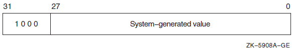
You define identifiers and their holders in the rights database with the Authorize utility or with the appropriate system services. Each user can hold multiple identifiers. This allows you to create a different kind of group designation from the one used with the user's UIC.
The alternative grouping described here permits each user to be a member of multiple overlapping groups. Access control lists (ACLs) define the access to protected objects based on the identifiers the user holds rather than on the user's UIC. See Section 16.5.3.1, ''Design Considerations'' for information on creating ACLs.
You can also define identifiers to represent particular terminals, times of day, or other site-specific environmental attributes. These identifiers are not given holder records in the rights database but may be granted to users by customer-written privileged software. This feature of the security system allows each site flexibility and, because the identifiers can be specific to the site, enhanced security. For a programming example demonstrating this technique, see Section 16.3.2.4, ''Determining Identifiers Held by a Holder''. For more information, also see the VSI OpenVMS Guide to System Security.
16.2.3. System-Defined Identifiers
|
BATCH |
All attempts at access made by batch jobs |
|
NETWORK |
All attempts at access made across the network |
|
INTERACTIVE |
All attempts at access made by interactive processes |
|
LOCAL |
All attempts at access made by users logged in at local terminals |
|
DIALUP |
All attempts at access made by users logged in at dialup terminals |
|
REMOTE |
All attempts at access made by users logged in on a network |
Depending on the environment in which the process is operating, the system includes one or more of these identifiers when creating the process rights list.
16.2.4. UIC Identifiers
Each UIC identifier is unique and represents a system user. By default, when an account is created, its UIC is associated with the account's user name generating an identifier value. When the high-order bit <31> of the identifier value is zero, the value identifies a UIC format identifier as shown in Figure 16.2, ''UIC Identifier Format''.
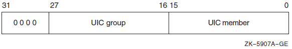
Bits <27:16> and <15:0> designate a group field and member field. Group numbers range from 1 through 16,382; member numbers range from 0 through 65,534.
16.2.5. Facility Identifiers
Facility-specific rights identifiers allow a range of unique binary identifier values to be reserved for a particular software product or application. Compare the format of facility-specific identifiers with the format of general identifiers and UIC identifiers, as shown in Section 16.2.1, ''Identifier Format''. The system normally determines the binary values of general identifiers when the system manager creates them; the system manager determines the binary values of UIC identifiers.
Figure 16.3, ''Facility-Specific Identifiers'' shows the facility-specific identifiers.
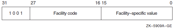
The binary value of a facility-specific identifier is determined at the time the application is designed. The facility number of the identifier must match the facility number the application has chosen for its condition and message codes. The remaining 16-bit facility-specific value may be assigned at will by the application designer. By reserving specific binary identifier values, the application designer may code fixed identifier values into an application's calls to $CHECK_PRIVILEGE, $GRANT_ID, and so forth. It avoids the added complexity of first having to translate an identifier name to binary with $ASCTOID.
An application can choose to register the identifiers in the rights database or not, depending on its needs. If the identifiers are registered, they are visible to the system manager who may grant them to users. In any case, they will be displayed properly if they appear on access control lists. If they are not registered, they will remain invisible to the system manager. Unregistered identifiers that appear on access control lists are displayed as a hexadecimal value.
To register its identifiers, the installation procedure of the application must run a program that enters the identifiers into the rights database using the $ADD_IDENT service. You cannot specify facility-specific identifier values to AUTHORIZE with the ADD/IDENTIFIER command.
Typically, facility-specific identifiers serve to extend the OpenVMS privilege mechanism for an application. For example, consider a database manager that includes a function to allow appropriately privileged users to modify a schema. Access to this function could be controlled through a facility-specific identifier named, for example, DBM$MOD_SCHEMA. The system manager grants the identifier to authorized persons using the AUTHORIZE command GRANT/ID. The database services that modify schemas use the $CHECK_PRIVILEGE service to check that the caller holds the identifier.
In another example, a privileged program run by users when they log in uses $GRANT_ID to grant the user certain facility-specific identifiers, depending on conditions determined by the program; for example, time of day or access port name. These identifiers can be placed on the ACLs of files to control file access, or they might be checked by other software with $CHECK_PRIVILEGE.
16.2.6. Identifier Attributes
An identifier has attributes associated with it in the rights database. The process rights list includes the attributes of any identifiers that the process holds.
| DYNAMIC |
Allows unprivileged holders of an identifier to add or remove the identifier from the process rights list using the DCL SET RIGHTS command. Conversely, an unprivileged user who does not have the attribute cannot modify the identifier. |
| HOLDER_HIDDEN |
Prevents someone from using the SYS$FIND_HOLDER system service to get a list of users who hold an identifier, unless that person holds the identifier. |
| NAME_HIDDEN |
Allows only the holders of an identifier to have it translated, either from binary to ASCII or from ASCII to binary. |
| NO_ACCESS |
Specifies that the identifier does not affect the access rights of the user holding the identifier. |
| RESOURCE |
Allows the holder of an identifier to charge resources, such as disk blocks, to an identifier. |
| SUBSYSTEM |
Allows holders of the identifier to create and maintain protected subsystems. |
Using the Resource Attribute
The following example demonstrates the advantages of defining an identifier and holders for a project.
Define an identifier PHYSICS with the Resource attribute in the rights database using the SYS$ADD_IDENT service.
- Enable disk quotas using SYSMAN as shown in the example.
$ MCR SYSMAN SYSMAN> DISKQUOTA CREATE/DEVICE=DKB0: SYSMAN> DISKQUOTA MODIFY/DEVICE=DKB0: PHYSICS /PERMQUOTA=150000 - _SYSMAN> /OVERDRAFT=5000 SYSMAN> EXIT
Create the common library and assign the identifier PHYSICS using the run-time library routine LIB$CREATE_DIR.
Grant the identifier PHYSICS to holders FRED, a faculty member, and GEORGE, a student, using the SYS$ADD_HOLDER service.
FRED NORESOURCE GEORGE RESOURCE NANCY NORESOURCE HAROLD RESOURCE SUSAN RESOURCE CHERYL NORESOURCE MARVIN NORESOURCE
#include <stdio.h> #include <descrip.h> #include <ssdef.h> #include <lib$routines.h> #include <kgbdef.h> #include <nam.h> #include <string.h> #include <stdlib.h> #define IDENT_LEN 31 #define NO_ATTR 0 #define RESOURCE 1 #define NORESOURCE 0 unsigned int sys$asctoid(), sys$add_ident(), sys$add_holder(), sys$idtoasc(), convert_id( struct dsc$descriptor_s, unsigned int ); void add_holder( unsigned int, unsigned int, unsigned int); struct { unsigned int uic; unsigned int terminator; }holder; static char ascii_ident[IDENT_LEN], abuffer[IDENT_LEN], dirbuf[NAM$C_MAXRSS], targbuf[IDENT_LEN]; $DESCRIPTOR(target,targbuf); unsigned int status; main() { FILE *ptr; char attr[11]; unsigned int owner_uic, attrib, resid, bin_id; $DESCRIPTOR(dirspec,dirbuf); $DESCRIPTOR(aident, abuffer); printf("\nEnter directory spec: "); gets(dirbuf); dirspec.dsc$w_length = strlen(dirbuf); printf("\nEnter its owner identifier: "); gets(targbuf); target.dsc$w_length = strlen(targbuf); /* Add target identifier WITH resource attribute to the rights database */ attrib = KGB$M_RESOURCE; status = sys$add_ident( &target, 0, attrib, &resid); if((status & 1) != SS$_NORMAL) lib$signal( status ); else printf("\nAdding identifier %s to rights database...\n", target.dsc$a_pointer); /* Create the common directory with the target id as owner */ owner_uic = resid; status = lib$create_dir( &dirspec, &owner_uic, 0, 0); if((status & 1) != SS$_NORMAL) lib$signal( status ); else printf("Creating the directory %s...\n",dirspec.dsc$a_pointer); /* Open an input file of UIC identifiers and attribute types */ if((ptr = fopen("USERLIST.DAT","r")) == NULL) { perror("OPEN"); exit(EXIT_FAILURE); } /* Read the input file of UIC identifiers */ while((fscanf(ptr,"%s %s\n",abuffer,attr)) != EOF) { aident.dsc$w_length = strlen(abuffer); attrib = (strcmp(attr,"RESOURCE")) == 0 ? KGB$M_RESOURCE : NO_ATTR; bin_id = convert_id( aident, attrib); add_holder( bin_id, resid, attrib ); } /* Close the input file */ fclose(ptr); } unsigned int convert_id( struct dsc$descriptor_s uic_id, unsigned int attr ) { unsigned int bin_id; status = sys$asctoid(&uic_id, &bin_id, &attr); if((status & 1) != SS$_NORMAL) lib$signal( status ); else { printf("Converting identifier %s to binary format...\n", uic_id.dsc$a_pointer); return bin_id; } } void add_holder( unsigned int bin_id, unsigned int resid, unsigned int attrib ) { int i; $DESCRIPTOR(nambuf, ascii_ident); holder.uic = bin_id; holder.terminator = 0; status = sys$add_holder( resid, &holder, attrib); if((status & 1) != SS$_NORMAL) lib$signal( status ); else { status = sys$idtoasc(bin_id, 0, &nambuf, 0, 0, 0); if((status & 1) != SS$_NORMAL) lib$signal( status ); /* Remove padding */ nambuf.dsc$w_length = strlen(ascii_ident); for(i=0;i < nambuf.dsc$w_length + 1; i++) if (ascii_ident[i] == 0x20) ascii_ident[i] = '\0'; printf("\nAdding holder %s to target identifier %s...\n", \ nambuf.dsc$a_pointer,target.dsc$a_pointer); } }
16.3. Rights Database
The rights database is an indexed file containing two types of records that define all identifiers: identifier records and holder records.
One identifier record appears in the rights database for each identifier. The identifier record associates the identifier name with its 32-bit binary value and specifies the attributes of the identifier. Figure 16.4, ''Format of the Identifier Record'' depicts the format of the identifier record.
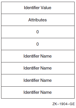
One holder record exists in the rights database for each holder of each identifier. The holder record associates the holder with the identifier, specifies the attributes of the holder, and identifies the UIC identifier of the holder. Figure 16.5, ''Format of the Holder Record'' depicts the format of the holder record.
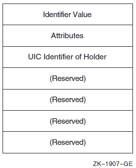
The rights database is an indexed file with three keys. The primary key is the identifier value, the secondary key is the holder ID, and the tertiary key is the identifier name. Through the use of the secondary key of the holder ID, all the identifiers held by a process can be retrieved quickly when the system creates the process's rights list.
16.3.1. Initializing a Rights Database
When a system is installed
With the Authorize utility
With the SYS$CREATE_RDB system service
When you call SYS$CREATE_RDB, you can use the
sysid argument to pass the system identification value
associated with the rights database. If you omit sysid, the
system uses the current system time in 64-bit format. If the rights database already
exists, SYS$CREATE_RDB fails with the error code
RMS$_FEX. To create a new rights database when one already
exists, you must explicitly delete or rename the old one.
You can specify the location and name of the rights database by defining the logical name RIGHTSLIST as a system logical name in executive mode; its equivalence string must contain the device, directory, and file name of the rights database.
The file RIGHTSLIST.DAT has the protection of (S:RWED,O:RWED,G:R,W).
In order to use SYS$CREATE_RDB, write access to the database is necessary. If the database is in SYS$SYSTEM, which is the default, you need he SYSPRV privilege to grant write access to the directory.
When SYS$CREATE_RDB initializes a rights database, system-defined identifiers, which describe the environment in which a process can operate, are automatically created.
To add any other identifiers to the rights database, you must define them with the Authorize utility or with the appropriate system service.
16.3.2. Using System Services to Affect a Rights Database
Identifier binary value
Identifier name
Holders of each identifier
Attribute of each identifier and each holder of each identifier
|
Action |
Element |
Service Used |
|---|---|---|
|
Translate |
Identifier name to identifier binary value |
SYS$ASCTOID |
|
Identifier binary value to identifier name |
SYS$IDTOASC | |
|
Add |
Identifier holder record |
SYS$ADD_HOLDER |
|
New identifier record |
SYS$ADD_IDENT | |
|
Find |
Identifier value held by holder |
SYS$FIND_HELD |
|
Holders of an identifier |
SYS$FIND_HOLDER | |
|
All identifiers |
SYS$IDTOASC | |
|
Modify |
Attribute in holder record |
SYS$MOD_HOLDER |
|
Attribute in identifier record |
SYS$MOD_IDENT | |
|
Delete |
Holder from identifier record |
SYS$REM_HOLDER |
|
Identifier and all its holders |
SYS$REM_IDENT |
16.3.2.1. Translating Identifier Values and Identifier Names
To the system, an identifier is a 32-bit binary value; however, to make identifiers easy to use, each binary value has an associated identifier name. The identifier value and the ASCII identifier name string are associated in the rights database. You can use the SYS$ASCTOID and SYS$IDTOASC system services to translate from one format to another. When you pass to SYS$ASCTOID the address of a string descriptor pointing to an identifier name, the corresponding identifier binary value is returned. Conversely, you use the SYS$IDTOASC service to translate a binary identifier value to an ASCII identifier name string.
Preventing a Translation
You can prevent a translation operation by unauthorized users by specifying the KGB$V_NAME_HIDDEN within an attributes mask.
Listing Identifiers in the Rights Database
You can also use the SYS$IDTOASC service to list the
identifier names of all of the identifiers in the rights database. Specify the
id argument as -1, initialize the
context argument to 0, and repeatedly call
SYS$IDTOASC until the status code
SS$_NOSUCHID is returned. The
SYS$IDTOASC service returns the identifier names in
alphabetical order. When SS$_NOSUCHID is returned,
SYS$IDTOASC clears the context longword and deallocates
the record stream. If you complete your calls to SYS$IDTOASC
before SS$_NOSUCHID is returned, use
SYS$FINISH_RDB to clear the context longword and to
deallocate the record stream.
Program ID_LIST
*
* Produce a list of all the identifiers
*
integer SYS$IDTOASC
external SS$_NORMAL, SS$_NOSUCHID
character*31 NAME
integer IDENTIFIER, ATTRIBUTES
integer ID/-1/, LENGTH, CONTEXT/0/
integer NAME_DSC(2)/31, 0/
integer STATUS
*
* Initialization
*
NAME_DSC(2) = %loc(NAME)
STATUS = %loc(SS$_NORMAL)
*
* Scan through the entire RDB ...
*
do while (STATUS .and. (STATUS .ne. %loc(SS$_NOSUCHID)))
STATUS = SYS$IDTOASC(%val(ID), LENGTH, NAME_DSC,
+ IDENTIFIER, ATTRIBUTES, CONTEXT)
if (STATUS .and. (STATUS .ne. %loc(SS$_NOSUCHID))) then
NAME(LENGTH+1:LENGTH+1) = ','
print 1, NAME, IDENTIFIER, ATTRIBUTES
1 format(1X,'Name: ',A31,' Id: ',Z8,', Attributes: ',Z8)
end if
end do
*
* Do we need to finish the RDB ???
*
if (STATUS .ne. %loc(SS$_NOSUCHID)) then
call SYS$FINISH_RDB(CONTEXT)
end if
end16.3.2.2. Adding Identifiers and Holders to the Rights Database
To add identifiers to the rights database, use the
SYS$ADD_IDENT service in a program. When you call
SYS$ADD_IDENT, use the name
argument to pass the identifier name you want to add. You can specify an identifier
value with the id argument; however, if you do not specify a
value, the system selects an identifier value from the general identifier
space.
In addition to defining the identifier value and identifier name, you use
SYS$ADD_IDENT to specify attributes in the identifier
record. Attributes are enabled for a holder of an identifier
only when they are set in both the identifier record and the
holder record. The attrib argument is a longword containing a
bit mask specifying the attributes. The symbol
KGB$V_RESOURCE, defined in the system macro library
$KGBDEF, sets the Resource bit in the attribute longword,
and the symbol KGB$V_DYNAMIC sets the Dynamic bit. (You can
use the prefix KGB$M rather than
KGB$V). See the description of
SYS$ADD_IDENT in the VSI OpenVMS System Services Reference Manual for a complete list
of symbols.
When SYS$ADD_IDENT successfully completes execution, a new identifier record containing the identifier value, the identifier name, and the attributes of the identifier exists in the rights database.
When the identifier record exists in the rights database, you define the holders
of that identifier with the SYS$ADD_HOLDER system service.
You pass the binary identifier value with the id argument and
you specify the holder with the holder argument, which is the
address of a quadword data structure in the following format. Figure 16.6, ''Format of the Holder Argument'' shows the format of the
holderargument.
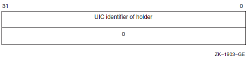
In the rights database, the holder identifier is in UIC format. You specify the
attributes of the holder with the attrib argument in the same
manner as with SYS$ADD_IDENT.
After SYS$ADD_HOLDER completes execution, a new holder record containing the binary value of the identifier that the holder holds, the attributes of the holder, and the UIC of the holder exists in the rights database.
16.3.2.3. Determining Holders of Identifiers
To determine the holders of a particular identifier, use the
SYS$FIND_HOLDER service in a program. When you call
SYS$FIND_HOLDER, use the id
argument to pass the binary value of the identifier whose holder you want to
determine. On successful execution, SYS$FIND_HOLDER returns
the holder identifier with the holder argument and the
attributes of the holder with the attrib argument.
You can identify all of the identifier's holders by initializing the
context argument to 0 and repeatedly calling
SYS$FIND_HOLDER, as detailed in Section 16.3.3, ''Search Operations''. Because SYS$FIND_HOLDER
identifies the records by the same key (holder ID), it returns the records in the
order in which they were written.
16.3.2.4. Determining Identifiers Held by a Holder
To determine the identifiers held by a holder, use the
SYS$FIND_HELD service in a program. When you call
SYS$FIND_HELD, use the holder
argument to specify the holder whose identifier is to be found.
On successful execution, SYS$FIND_HELD returns the identifier's binary identifier value and attributes.
You can identify all the identifiers held by the specified holder by initializing
the context argument to 0 and repeatedly calling
SYS$FIND_HELD, as detailed in Section 16.3.3, ''Search Operations''. Because SYS$FIND_HELD
identifies the records by the same key (identifier), it returns the records in the
order in which they were written.
16.3.2.5. Modifying the Identifier Record
To modify an identifier record by changing the identifier's name, value, or
attributes, or all three in the rights database, use the
SYS$MOD_IDENT service in a program. Use the
id argument to pass the binary value of the identifier
whose record you want to modify. To enable attributes, use the
set_attrib argument, which is a longword containing a bit
mask specifying the attributes. The symbol KGB$V_RESOURCE,
defined in the system macro library $KGBDEF, sets the
Resource bit in the attribute longword. The symbol
KGB$V_DYNAMIC sets the Dynamic bit.(You can use the
prefix KGB$M rather than KGB$V).
See the description of SYS$MOD_IDENT in the VSI OpenVMS System Services Reference Manual
for a complete list of symbols.
If you want to disable the attributes for the identifier, use the
clr_attrib argument, which is a longword containing a bit
mask specifying the attributes. If the same attribute is specified in
set_attrib and clr_attrib, the
attribute is enabled.
You can also change the identifier name, value, or both with the
new_name and new_value arguments.
The new_name argument is the address of a descriptor pointing
to the identifier name string; new_value is a longword
containing the binary identifier value. If you change the value of an identifier that
is the holder of other identifiers (a UIC, for example),
SYS$MOD_IDENT updates all the corresponding holder
records with the new holder identifier value.
When SYS$MOD_IDENT successfully completes execution, a new identifier record containing the identifier value, the identifier name, and the attributes of the identifier exists in the rights database.
16.3.2.6. Modifying a Holder Record
To modify a holder record, use the SYS$MOD_HOLDER service
in a program. When you call SYS$MOD_HOLDER, use the
id argument and the holder argument
to pass the binary identifier value and the UIC holder identifier whose holder record
you want to modify.
Use the SYS$MOD_HOLDER service to enable or disable the attributes of an identifier in the same way as with SYS$MOD_HOLDER.
When SYS$MOD_HOLDER completes execution, a new holder record containing the identifier value, the identifier name, and the attributes of the identifier exists in the rights database.
Program MOD_HOLDER
*
* Modify the attributes of all the holders of identifiers to reflect
* the current attribute setting of the identifiers themselves.
*
external SS$_NOSUCHID
parameter KGB$M_RESOURCE = 1, KGB$M_DYNAMIC = 2
integer SYS$IDTOASC, SYS$FIND_HELD, SYS$MOD_HOLDER
*
* Store information about the holder here.
*
integer HOLDER(2)/2*0/
equivalence (HOLDER(1), HOLDER_ID)
integer HOLDER_NAME(2)/31, 0/
integer HOLDER_ID, HOLDER_CTX/0/
character*31 HOLDER_STRING
*
* Store attributes here.
*
integer OLD_ATTR, NEW_ATTR, ID_ATTR, CONTEXT
*
* Store information about the identifier here.
*
integer IDENTIFIER, ID_NAME(2)/31, 0/
character*31 ID_STRING
integer STATUS
*
* Initialize the descriptors.
*
HOLDER_NAME(2) = %loc(HOLDER_STRING)
ID_NAME(2) = %loc(ID_STRING)
*
* Scan through all the identifiers.
*
do while
+ (SYS$IDTOASC(%val(-1),, HOLDER_NAME, HOLDER_ID,, HOLDER_CTX)
+ .ne. %loc(SS$_NOSUCHID))
*
* Test all the identifiers held by this identifier (our HOLDER).
*
if (HOLDER_ID .le. 0) go to 2
CONTEXT = 0
do while
+ (SYS$FIND_HELD(HOLDER, IDENTIFIER, OLD_ATTR, CONTEXT)
+ .ne. %loc(SS$_NOSUCHID))
*
* Get name and attributes of held identifier.
*
STATUS = SYS$IDTOASC(%val(IDENTIFIER),, ID_NAME,, ID_ATTR,)
*
* Modify the holder record to reflect the state of the identifier itself.
*
if ((ID_ATTR .and. KGB$M_RESOURCE) .ne. 0) then
STATUS = SYS$MOD_HOLDER
+ (%val(IDENTIFIER), HOLDER, %val(KGB$M_RESOURCE),)
NEW_ATTR = OLD_ATTR .or. KGB$M_RESOURCE
else
STATUS = SYS$MOD_HOLDER
+ (%val(IDENTIFIER), HOLDER,, %val(KGB$M_RESOURCE))
NEW_ATTR = OLD_ATTR .and. (.not. KGB$M_RESOURCE)
end if
if ((ID_ATTR .and. KGB$M_DYNAMIC) .ne. 0) then
STATUS = SYS$MOD_HOLDER
+ (%val(IDENTIFIER), HOLDER, %val(KGB$M_DYNAMIC),)
NEW_ATTR = OLD_ATTR .or. KGB$M_DYNAMIC
else
STATUS = SYS$MOD_HOLDER
+ (%val(IDENTIFIER), HOLDER,, %val(KGB$M_DYNAMIC))
NEW_ATTR = OLD_ATTR .and. (.not. KGB$M_DYNAMIC)
end if
*
* Was it successful?
*
if (.not. STATUS) then
NEW_ATTR = OLD_ATTR
call LIB$SIGNAL(%val(STATUS))
end if
*
* Report it all.
*
print 1, HOLDER_STRING, ID_STRING,
+ OLD_ATTR, ID_ATTR, NEW_ATTR
1 format(1X, 'Holder: ', A31, ' Id: ', A31,
+ ' Old: ', Z8, ' Id: ', Z8, ' New: ', Z8)
end do
2 continue
end do
end16.3.2.7. Removing Identifiers and Holders from the Rights Database
To remove an identifier and all of its holders, use the
SYS$REM_IDENT service in a program. When you call
SYS$REM_IDENT, use the id argument
to pass the binary value of the identifier you want to remove. When
SYS$REM_IDENT completes execution, the identifier and all
of its associated holder records are removed from the rights database.
To remove a holder from the list of an identifier's holders, use the
SYS$REM_HOLDER service in a program. When you call
SYS$REM_HOLDER, use the id
argument and the holder argument to pass the binary ID value
and the UIC identifier of the holder whose holder record you want to delete.
On successful execution, SYS$REM_HOLDER removes the holder from the list of the identifier's holders.
16.3.3. Search Operations
You can search the entire rights database when you use the SYS$IDTOASC, SYS$FIND_HELD, and SYS$FIND_HOLDER services. You initialize the context longword to 0 and repeatedly call one of the three services until the status code SS$_NOSUCHID is returned. When SS$_NOSUCHID is returned, the service clears the context longword and deallocates the record stream. If you complete your calls to one of these services before SS$_NOSUCHID is returned, you must use SYS$FINISH_RDB to clear the context longword and to deallocate the record stream.
The structure of the rights database affects the order in which each of these services returns the records when you search the rights database. The rights database is an indexed file with three keys. The primary key is the identifier binary value, the secondary key is the holder UIC identifier, and the tertiary key is the identifier name.
During a searching operation, the service obtains the first record with an indexed OpenVMS RMS GET operation. The key used for the GET operation depends on the service. The SYS$FIND_HOLDER service uses the identifier binary value; SYS$FIND_HELD uses the holder UIC identifier. After the indexed GET, the service returns the records with sequential RMS GET operations. Consequently, the file organization, the key used for the first GET operation, and the order in which the records were originally written in the database determine the order of records returned.
|
Service |
Record Order |
|---|---|
|
SYS$IDTOASC |
Identifier name order. |
|
SYS$FIND_HELD |
First GET operation – holder key. Subsequent records are returned in the order in which they were written. |
|
SYS$FIND_HOLDER |
First GET operation – identifier key. Subsequent records are returned in the order in which they were written. |
Module ID_HOLDER
( main = MAIN,
addressing_mode(external=GENERAL) ) =
begin
!
! Produce a list of all the identifiers, that have holders,
! with their respective holders.
!
!
! Declarations:
!
library
'SYS$LIBRARY:LIB';
forward routine
MAIN;
external routine
LIB$PUT_OUTPUT,
SYS$FAO,
SYS$IDTOASC,
SYS$FINISH_RDB,
SYS$FIND_HOLDER;
!
! To create static descriptors
!
macro S_DESCRIPTOR[NAME, SIZE] =
own
%name(NAME, '_BUFFER'): block[%number(SIZE), byte],
%name(NAME): block[DSC$K_S_BLN, byte]
preset( [DSC$B_CLASS] = DSC$K_CLASS_S,
[DSC$W_LENGTH] = %number(SIZE),
[DSC$A_POINTER] = %name(NAME, '_BUFFER') ); %;!
! Descriptors for ID, holder NAME, and output LINE
!
S_DESCRIPTOR('ID_NAME', 31);
S_DESCRIPTOR('NAME', 31);
S_DESCRIPTOR('LINE', 76);
own
STATUS,
ID,
ID_LENGTH,
ID_CONTEXT: initial(0),
HOLDER,
LENGTH,
CONTEXT: initial(0),
ATTRIBS,
VALUE,
LINE_: block[DSC$K_S_BLN, byte]
preset( [DSC$B_CLASS] = DSC$K_CLASS_S,
[DSC$A_POINTER] = LINE_BUFFER );
!
! To check for existence of an ID or HOLDER
!
macro CHECK(EXPRESSION) =
(STATUS = %remove(EXPRESSION)) and (.STATUS neq SS$_NOSUCHID) %;
!
! List all the identifiers, which have holders, with their holders.
!
routine MAIN =
begin
!
! Examine all IDs (-1).
!
while
CHECK(<SYS$IDTOASC(-1, ID_LENGTH, ID_NAME, ID, ATTRIBS, ID_CONTEXT)>)
do
begin
CONTEXT = 0;
!
! Find all holders of ID.
!
while CHECK(<SYS$FIND_HOLDER(.ID, HOLDER, ATTRIBS, CONTEXT)>) do
begin
!
! Translate the HOLDER to find its NAME.
!
SYS$IDTOASC(.HOLDER, LENGTH, NAME, VALUE, ATTRIBS, 0);!
! Print a message reporting ID and HOLDER.
!
SYS$FAO( %ascid'Id: !AD, Holder: !AD',
LINE_[DSC$W_LENGTH], LINE,
.ID_LENGTH, .ID_NAME[DSC$A_POINTER],
.LENGTH, .NAME[DSC$A_POINTER] );
LIB$PUT_OUTPUT(LINE_);
end;
end;
return SS$_NORMAL;
end;
end
eludom16.3.4. Modifying a Rights List
When a process is created, LOGINOUT builds a rights list for the process consisting of the identifiers the user holds and any appropriate environmental identifiers. A system rights list is the default rights list used in addition to any process rights list. Modifications to the system rights list effectively become modifications to the rights of each process.
A privileged user can alter the process or system rights list with the SYS$GRANTID or SYS$REVOKID services. These services are not intended for the general system user. Use of these services requires CMKRNL privilege. The SYS$GRANTID service adds an identifier to a rights list or, if the identifier is already part of the rights list, the SYS$GRANTID service modifies the attributes of the identifier. The SYS$REVOKID service removes an identifier from a rights list.
The SYS$GRANTID and SYS$REVOKID
services treat the pidadr and prcnam
arguments the same way all other process control services treat these arguments. For
more details, see the VSI OpenVMS Guide to System Security.
You can also modify the process or system rights list with the DCL command SET RIGHTS_LIST. Additionally, you can use SET RIGHTS_LIST to modify the attributes of the identifier if the identifier is already part of the rights list. Note that you cannot use the SETRIGHTS_LIST command to modify the rights database from which the rights list was created. For more information about using the SET RIGHTS_LIST command, see the VSI OpenVMS DCL Dictionary.
16.4. Persona (Alpha and I64 Only?)
A persona contains a user's security profile. The persona contains all identity and credential information about the process, including the username, UIC, privileges masks, and rights identifiers. Every process in the system has at least one persona, the natural persona of the process. The natural persona is created during process creation. OpenVMS stores a persona in a single data structure, the Persona Security Block (PSB).
UIC
Persona and system rights chains
Permanent, authorized, and working privileges
Account name
User name
Auditing flags and counters
16.4.1. Impersonation Services (Alpha and I64 Only)
For client/server applications, the server processes requests on behalf of the client. With OpenVMS, the server application developer can use impersonation services for client requests. This mechanism allows the operating system to perform object access checking (and auditing) for the server.
The impersonation system services allow a privileged OpenVMS process to create and use personae. A process, for example a server, can acquire more Persona System Blocks and switch between them using impersonation system services, such as SYS$PERSONA_CREATE, SYS$PERSONA_ASSUME, and SYS$PERSONA_CLONE. Each process has a persona array which is used to store the addresses of all PSBs allocated to the process. Other impersonation services support PSB lookup and attribute retrieval and modification, such as SYS$PERSONA_FIND, SYS$PERSONA_QUERY, and SYS$PERSONA_MODIFY, respectively.
16.4.1.1. Using Impersonation System Services
The following discussion assumes there is a running server that has the ability to impersonate clients and is able to perform work requests for clients. This could be a file server, for example.
Switch the server's execution context to the client's profile, which has been previously created, by having the server call SYS$PERSONA_ASSUME, specifying the client's persona.
Make copies of the created profile and then execute client requests under thread control with a multithreaded server. That is, the server calls the SYS$PERSONA_CLONE service, specifying the client's persona as input, resulting in a copy. The server can now handle multiple requests from the client, using an available copy of the client's persona as input to SYS$PERSONA_ASSUME.
Check to determine if a given client's profile already exists by calling SYS$PERSONA_FIND. The SYS$PERSONA_FIND service enables the caller to find the personae, within a process, that have certain attributes or settings. For example, the service could specify the USERNAME item as an attribute.
Check the client's profile, since some client requests may require certain privileges or rights, by calling SYS$PERSONA_QUERY, specifying the persona to check and the items to retrieve. If required and allowable, the server can update the person's working privileges or rights by calling SYS$PERSONA_MODIY, specifying the client's persona and the attributes to change.
Remove a client's profiles with a client disconnects. The server again could use SYS$PERSONA_FIND to locate personae that match the client's USERNAME attribute. The server invokes SYS$PERSONA_DELETE to remove the specified persona from the server's process.
For more information about the persona system services, see the VSI OpenVMS System Services Reference Manual: GETUTC–Z.
16.4.2. Per-Thread Security (Alpha and I64 Only)
OpenVMS provides per-thread security capabilities. With per-thread security, a multithreaded process allows each thread of execution to have an individual security profile. That is, a PSB is bound to a thread of execution. Each process has at least one kernel thread. The kernel thread block (KTB) points to the PSB for the currently active thread. Individual user threads can point to different PSBs, which give each user thread a separate identity. Per-thread security profiles are supported by impersonation system services and changes to the underlying system framework.
16.4.2.1. Previous Security Model
Prior to OpenVMS V7.2, the information that constitutes a user's security profile was bound at the process level, common to all threads of execution within a process. Figure 16.7, ''Previous Per-Thread Security Model'' shows this relationship.
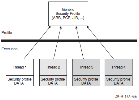
Whether multiple threads can truly execute simultaneously
How the threads perform profile management among themselves
16.4.2.2. Per-Thread Security Model
As of OpenVMS Version 7.2, the users' security profile (that is, their privileges, rights, and identifier information) is shifted from the process level to the user thread level. The security information previously stored in several structures, including the Access Rights Block (ARB), the Process Control Block (PCB), the Process Header Descriptor (PHD), the Job Information Block (JIB), and the Control (CTL) region fields, has moved to the new Persona Security Block (PSB) data structure.
Each thread of execution can share a security profile with other threads or have a thread-specific security profile. Figure 16.8, ''Per-Thread Security Profile Model''shows these relationships.
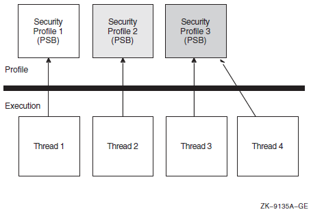
As is the case with the previous model, modifications to a shared profile are potentially visible to all threads that share the profile. However, modifications made to a thread-specific profile are only applicable to the particular thread.
For more information about per-thread security, see the VSI OpenVMS Guide to System Security.
16.4.3. Persona Extensions (Alpha and I64 Only)
A persona extension is a mechanism to attach support for additional security credentials into the already existing persona support. This mechanism consists of extension-specific execlet-based code and an extension-specific data structure (PXB)attached to an existing persona block (PSB).
To extend these capabilities, persona extension blocks (PXBs) that represent id entity and credential information of a security agent other than OpenVMS can be attached to a PSB. The process can therefore have multiple identities: for example, one for OpenVMS and one for NT.
An extension is more than just a data structure attached to a PSB. Routines provided by the extension are called to process the extension data structure. This leaves the layout of the PXB completely up to the author of the extension support routines. A new credential/security extension can be added to a system by simply creating the new extension routines that describe a PXB. This capability will be added in a future release of OpenVMS.
The new and existing SYS$PERSONA system services invoke extension-specific support routines on behalf of the registered extensions. The services also handle new item codes that describe values stored in the PXB. Besides operating on items for individually named extension-specific data, the services use other item codes to establish a current PXB on which subsequent items operate. Before using an extension-specific item code, that extension must be switched to by using the SWITCH_EXTENSION item code. A generic set of item codes pointing to generally useful PXB values (for example, principal name and domain) can be used to fetch these values without concern for the extension-specific name.
16.5. Managing Object Protection
(IDENTIFIER=GREEN,ACCESS=WRITE+READ+CONTROL)
(IDENTIFIER=YELLOW,ACCESS=READ)
(IDENTIFIER=RED,ACCESS=NOACCESS)Managing object protection involves using system services to manipulate protection codes, UICs, and ACEs; that is, creating, translating, and maintaining ACEs, establishing object ownership, and manipulating the protection codes of protected objects.
16.5.1. Protected Objects
|
Class Name |
Description |
|---|---|
|
Capability? |
A resource to which the system controls access; currently, the only defined capability is the vector processor. |
|
Common event flag cluster |
A set of 32 event flags that enable cooperating processes to post event notifications to each other. |
|
Device |
A class of peripherals connected to a processor that are capable of receiving, storing, or transmitting data. |
|
File |
Files-11 On-Disk Structure Level 2 (ODS-2) files and directories. |
|
Group global section |
A shareable memory section potentially available to all processes in the same group. |
|
Logical name table |
A shareable table of logical names and their equivalence names for the system or a particular group. |
|
Queue |
A set of jobs to be processed in a batch, terminal, server, or print job queue. |
|
Resource domain |
A namespace controlling access to the lock manager's resources. |
|
Security class |
A data structure containing the elements and management routines for all members of the security class. |
|
System global section |
A shareable memory section potentially available to all processes in the system. |
|
Volume |
A mass storage medium, such as a disk or tape, that is in ODS-2 format. Volumes contain files and may be mounted on devices. |
16.5.2. Object Security Profile
The security profile summarizes the various types of protection mechanisms applied to a protected object. The security profile associates a protected object with an owner, a protection code, and optionally an ACL. When a user or process requests access to a protected object, the system compares the user's privileges and identifiers in the system authorization database with appropriate elements in the object's security profile.
16.5.2.1. Displaying the Security Profile
LNM$GROUP object of class LOGICAL_NAME_TABLE
Owner: [ACCOUNTING]
Protection: (System: RWCD, Owner: RWCD, Group: R, World: R)
Access Control List:
(IDENTIFIER=[USER,CHEHKOV],ACCESS=CONTROL)
(IDENTIFIER=[USER,VANNEST],ACCESS=READ+WRITE)After you have returned owner and protection code information, you can call SYS$GET_SECURITY iteratively to return each ACE in the ACL (if it exists) or you can read the entire ACL. In addition, you can perform iterative searches to retrieve objects and their templates.
16.5.2.2. Modifying the Security Profile
You can modify all the security characteristics listed in a protected object's profile by using the SYS$SET_SECURITY system service. You can add or delete ACEs in the ACL selectively or you can delete the entire ACL. You have the option of modifying a local copy of the profile without altering the master copy using the OSS$M_LOCAL flags or you can modify the master copy directly. Also, use the context to release the context structure after the service completes execution.
16.5.3. Types of Access Control Entries
|
ACE |
Description |
|---|---|
|
Alarm |
Sets an alarm |
|
Application |
Contains application-dependent information |
|
Audit |
Sets a security audit |
|
Creator |
Controls access to an object based on creators |
|
Default Protection |
Specifies the default protection for all files and subdirectories created in the directory |
|
Identifier |
Controls the type of access allowed based on identifiers |
|
Subsystem |
Maintains protected subsystems |
For information about the structure of specific types of ACEs, see the SYS$FORMAT_ACL system service in VSI OpenVMS System Services Reference Manual.
You use SYS$FORMAT_ACL and SYS$PARSE_ACL to translate ACEs from one format to another in the same way that SYS$IDTOASC and SYS$ASCTOID translate identifiers from binary to text format and text to binary format.
|
Service |
Description |
|---|---|
|
SYS$FORMAT_ACL |
Converts an ACE from binary format to ASCII text |
|
SYS$GET_SECURITY |
Retrieves the security characteristics of an object |
|
SYS$PARSE_ACL |
Converts an ACE from ASCII text to binary format |
|
SYS$SET_SECURITY |
Modifies the security characteristics of a protected object |
16.5.3.1. Design Considerations
Before you attempt to manipulate ACLs, you should understand the meaning and relationship among existing identifiers. If you are populating a previously empty ACL, you need to plan the access types and position of each ACE within the ACL.
The position of the ACE within the ACL is an important consideration when creating an ACE. By default, ACEs are added to the top of an ACL. The ACL management services accept options allowing you to control the placement of ACEs. The system compares the identifiers granted to the process requesting access with those associated with the object starting with the top ACE in the object's ACL. Once a matching identifier name is found in the object's ACL, the search stops.
16.5.3.2. Translating ACEs
To translate ACEs from binary format to a text string, use the
SYS$FORMAT_ACL service. The aclent
argument is the address of a descriptor pointing to a buffer containing the
description of the ACE. The first byte of the buffer contains the length of the ACE
and the second byte contains the type, which in turn defines the format of the ACE.
acllen argument specifies the length of the text string
written to the buffer pointed to by aclstr. You use the
width, trmdsc, and
indent arguments to specify a particular width, termination
character, and number of blank characters for an ACE. The
accnam argument contains the address of an array of 32
quadword descriptors called an access name table. The access
name table defines the names of the bits in the access mask of the ACE. The access
mask defines the access types associated with a protected object. Use run-time
library (RTL) routine LIB$GET_ACCNAM described in the
VSI OpenVMS RTL Library (LIB$) Manual to obtain the address of the access name table. If
accnam is omitted, the following names are
used:Bit <0> READ Bit <1> WRITE Bit <2> EXECUTE Bit <3> DELETE Bit <4> CONTROL Bit <5> BIT_5 Bit <6> BIT_6 . . . Bit <31> BIT_31
The SYS$PARSE_ACL service translates an ACE from text
string format to binary format. The aclstr argument is the
address of a string descriptor pointing to the ACE text string. As with
SYS$FORMAT_ACL, the aclent
argument is the address of a descriptor pointing to a buffer containing the
description of the ACE. The first byte of the buffer contains the length of the ACE
and the second byte contains the type, which in turn defines the format of the ACE.
If SYS$PARSE_ACL fails, the errpos
argument points to the failing point in the string. The accnam
argument contains the address of an array of 32 quadword descriptors that define the
names of the bits in the access mask of the ACE. If accnam is
omitted, the names specified in the description of
SYS$FORMAT_ACL are used.
16.5.3.3. Creating and Maintaining ACEs
The SYS$GET_SECURITY and SYS$SET_SECURITY system services replace the SYS$CHANGE_ACL system service. The VSI OpenVMS System Services Reference Manual: A–GETUAI and the VSI OpenVMS System Services Reference Manual: GETUTC–Z describe these system services.
To create or modify an ACL associated with a protected object, you use the
SYS$SET_SECURITY service. You specify the object whose
ACL is to be modified with either the objhan argument, which
specifies the I/O channel associated with the object, or the
objnam argument, which specifies the object name. If you
specify objnam, objhan must be omitted
or specified as 0. The clsnam argument specifies the type of
object.
Use the acmode argument to specify the access mode used
when checking file access protection. By default, kernel mode is used, but the system
compares acmode against the caller's access mode and uses the
least privileged mode. VSI recommends that this argument be omitted (passed as
zero).
itmlst argument, you can manipulate only the
security profile locks or release contxt resources.|
Item Code |
Description |
|---|---|
|
OSS$_ACL_ADD_ENTRY |
Adds an access control entry (ACE) |
|
OSS$_ACL_DELETE |
Deletes all unprotected ACEs from an ACL |
|
OSS$_ACL_DELETE_ALL |
Deletes the ACL, including protected ACEs |
|
OSS$_ACL_DELETE_ENTRY |
Deletes an ACE |
|
OSS$_ACL_FIND_ENTRY |
Locates an ACE |
|
OSS$_ACL_FIND_NEXT |
Moves the current position to the next ACE in the ACL |
|
OSS$_ACL_FIND_TYPE |
Locates an ACE of the specified type |
|
OSS$_ACL_MODIFY_ENTRY |
Replaces an ACE at the current position |
|
OSS$_ACL_POSITION_BOTTOM |
Sets a marker that points to the end of the ACL |
|
OSS$_ACL_POSITION_TOP |
Sets a marker that points to the beginning of the ACL |
|
OSS$_OWNER |
Sets the UIC or general identifier of the object's owner |
|
OSS$_PROTECTION |
Sets the protection code of the object |
16.6. Protected Subsystems
A protected subsystem is a set of application programs that allows controlled access to objects. It has under its control one or more protected objects and a gatekeeper application. Users cannot access the objects within the subsystem unless they execute the gatekeeper application. Once users have successfully executed the application, their process rights list acquires the identifiers necessary to access objects owned by the subsystem. The identifiers allow processes to use the resources of the subsystem. When the application completes execution or the user exits, the identifiers are removed from the user's process rights list. Protected subsystems are an alternative to creating privileged images and protected shareable images (user-written system services), and help prevent the overuse of privileges.
Roles and Responsibilities
UAF> ADD/IDENTIFIER FOO/ATTRIBUTES=SUBSYSTEM UAF> GRANT/IDENTIFIER FOO FRANK /ATTRIBUTES=SUBSYSTEM
$ SET SECURITY BLOP.EXE - _$ /ACL=(SUBSYSTEM, IDENTIFIER=FOO) - $ SET SECURITY BLOP.DAT - _$ /ACL=(IDENTIFIER=FOO, ACCESS=READ+WRITE) - $ SET SECURITY BLOP.EXE - _$ /ACL=(IDENTIFIER=HARRY, ACCESS=EXECUTE) -
Finally, a user uses the protected subsystem to access data available only through the subsystem.
Subsystem Security
During the execution of a protected subsystem, $IMGACT adds subsystem identifiers to the image rights list. What happens if the user presses the Ctrl/Y key sequence during execution? Will the user retain whatever privileges were granted by the subsystem? If the user presses Ctrl/Y, image identifiers are removed from the process. Also, subprocesses do not inherit image identifiers by default. However, SYS$CREPRC and LIB$SPAWN do contain flags PRC$M_SUBSYSTEM and SUBSYSTEM, respectively, that allow subprocesses to inherit image identifiers.
16.7. Security Auditing
|
Service |
Description |
|---|---|
|
SYS$AUDIT_EVENT |
Appends an event message to the system audit log file or sends an alarm to a security operator terminal |
|
SYS$CHECK_PRIVILEGE |
Determines whether the caller has the specified privileges or identifiers |
The system service SYS$AUDIT_EVENT is used to report security events to the auditing system. It examines the settings of the DCL command SETAUDIT to determine if an event is enabled for auditing. If the event is enabled for alarms or audits, SYS$AUDIT_EVENT generates an audit record and appends it to the system audit log file (or sends an alarm to a security operator terminal) that identifies the process involved and lists information supplied by its caller.
16.8. Checking Access Protection
|
Service |
Description |
|---|---|
|
SYS$CHECK_ACCESS |
Invokes a system access protection check on behalf of another user |
|
SYS$CHKPRO |
Invokes a system access protection check |
The SYS$CHKPRO and SYS$CHECK_ACCESS system services have been extended to support auditing. The VSI OpenVMS Guide to System Security describes how to use the auditing function. The VSI OpenVMS System Services Reference Manual: A–GETUAI describes how to use the two system services. These services are described in the following sections.
16.8.1. Creating a Security Profile
The SYS$CREATE_USER_PROFILE system service returns a user profile, using information in the rights database and the system authorization database to generate the profile. The system services SYS$CHECK_ACCESS or SYS$CHKPRO accept as input the profile from SYS$CREATE_USER_PROFILE.
16.8.2. SYS$CHKPRO System Service
The SYS$CHKPRO system service invokes the access protection check used by the system. The service does not grant or deny access; rather, it performs the protection check. Subsequently, an application might grant or deny access to the specified object.
To pass the input and output information to SYS$CHKPRO, use
the itmlst argument, which is the address of an item list of
descriptors. The SYS$CHKPRO service compares the item list of
the rights and privileges of the accessor to a list of the protection attributes of the
object to be accessed. If the accessor can access the object,
SYS$CHKPRO returns the status
SS$_NORMAL; if the accessor cannot access the object,
SYS$CHKPRO returns the status
SS$_NOPRIV. The SYS$CHKPRO service
does not grant or deny access. The subsystem itself must grant or deny access based on
the output (SS$_NORMAL or SS$_NOPRIV)
from SYS$CHKPRO.
The SYS$CHKPRO service also returns an item list of the rights or privileges that allowed the accessor access to the object, as well as the names of security alarms raised by the access attempt. For information about the item codes defined for SYS$CHKPRO, see the description of SYS$CHKPRO in the VSI OpenVMS System Services Reference Manual.
See the VSI OpenVMS Guide to System Security for a flowchart describing how SYS$CHKPRO evaluates an access request attempt.
16.8.3. SYS$CHECK_ACCESS System Service
The SYS$CHECK_ACCESS service performs a protection check on a third-party accessor. An example of this is a file server program that uses SYS$CHECK_ACCESS to ensure that an accessor (the third party) requesting a file has the required privileges to do so.
You pass the input and output information to
SYS$CHECK_ACCESS by using the itmlst
argument, which is the address of an item list of descriptors. You also pass the name of
the accessor and the name and type of the object being accessed by using the
usrnam, objnam, and
objtyp arguments, respectively. The
SYS$CHECK_ACCESS service compares the rights and privileges
of the accessor to a list of the protection attributes of the object to be accessed. If
the accessor can access the object, SYS$CHECK_ACCESS returns
the status SS$_NORMAL; if the accessor cannot access the
object, SYS$CHECK_ACCESS returns the status
SS$_NOPRIV.
The SYS$CHECK_ACCESS service does not grant or deny access. The subsystem itself must explicitly grant or deny access based on the output (SS$_NORMAL or SS$_NOPRIV) from SYS$CHECK_ACCESS.
The SYS$CHECK_ACCESS service also returns an item list of the rights or privileges that allowed the accessor to access the object, as well as the names of security alarms raised by the access attempt. For information about the item codes defined for SYS$CHECK_ACCESS, see the description of SYS$CHECK_ACCESS in the VSI OpenVMS System Services Reference Manual.
16.9. SYS$CHECK_PRIVILEGE
The SYS$CHECK_PRIVILEGE system service determines whether the caller has the specified privileges or identifiers. The service performs the privilege check and looks at the SET AUDIT settings to determine whether the system administrator enabled privilege auditing. When privilege auditing is enabled, SYS$CHECK_PRIVILEGE generates an audit record. The audit record identifies the process (subject) and privilege involved, provides the result of the privilege check, and lists supplemental event information supplied by its caller. Privilege audit records usually contain either the DCL command line or the system service name associated with the privilege check.
SYS$CHECK_PRIVILEGE completes asynchronously; that is, it does not wait for final status. For synchronous completion, use the SYS$CHECK_PRIVILEGEW service.
16.10. Implementing Site-Specific Security Policies
Occasionally, you may need to write routines that implement site-specific policies or special algorithms. The routines that you write can either replace or augment built-in operating system policies. This section contains instructions for replacing key operating system security routines with routines that are specific to your site. Two types of routines are discussed: loadable system services and shareable images.
16.10.1. Creating Loadable Security Services
This section describes how to create a system service image and how to update the SYS$LOADABLE_IMAGES:VMS$SYSTEM_IMAGES.DATA file, which controls site-specific loading of system images. These procedures update the loading of system images for all nodes of a cluster.
|
Service |
Description |
|---|---|
|
SYS$ERAPAT |
Generates a security erasure pattern |
|
SYS$MTACCESS |
Controls magnetic tape access |
|
SYS$HASH_PASSWORD |
Applies a hash algorithm to an ASCII password |
When you create the system service, you code the source module and define the vector offsets, the entry point, and the program sections for the system service. Then, you can assemble and link the module to create a loadable image.
Once you have created the loadable image, you install it. First, you copy the image into the SYS$LOADABLE_IMAGES directory and add an entry for it in the operating system's images file using the System Management utility (SYSMAN). Next, you invoke the system images command procedure to generate a new system image data file. Finally, you reboot the system to load your service.
Note
- DOD_ERAPAT.MAR
- HASH_PASSWORD.MAR
- DOD_ERAPAT_LNK.COM
- VMS$PASSWORD_POLICY_LINK.COM
You can find an example of the SYS$ERAPAT system service in SYS$EXAMPLES:DOD_ERAPAT.MAR on a VAX system. The description here also applies to the Hash Password (SYS$HASH_PASSWORD) and Magnetic Tape Accessibility (SYS$MTACCESS) system services. You can find an example of how to prepare and load the SYS$HASH_PASSWORD service in SYS$EXAMPLES:HASH_PASSWORD.MAR on a VAX system.
16.10.1.1. Preparing and Loading a System Service
- Create the source module.
- Include the following macro to define system service vector offsets:
$SYSVECTORDEF ; Define system service vector offsets - Use the following macro to define the system service entry point:
SYSTEM_SERVICE ERAPAT, - ; Entry point name <R4>, - ; Register to save MODE=KERNEL,- ; Mode of system service NARG=3 ; Number of arguments(The code immediately following this macro is the first instruction of the SYS$ERAPAT system service).
- Use the following macros to declare the desired program sections:
DECLARE_PSECT EXEC$PAGED_CODE ; Pageable code PSCET DECLARE_PSECT EXEC$PAGED_DATA ; Pageable data PSECT DECLARE_PSECT EXEC$NONPAGED_DATA ; Nonpageable data PSECT DECLARE_PSECT EXEC$NONPAGED_CODE ; Nonpageable code PSCET
- Assemble the source module by using the following command:
$ MACRO DOD_ERAPAT+SYS$LIBRARY:LIB.MLB/LIB - Link the module to create a SYS$ERAPAT.EXE executive loaded image. You can link the module using the command procedure DOD_ERAPAT_LNK.COM in SYS$EXAMPLES on a VAX system. (A command procedure is also available to link the SYS$HASH_PASSWORD example). To link the SYS$ERAPAT module, enter the following command:
$ @SYS$EXAMPLES:DOD_ERAPAT_LNK.COM - Prepare the operating system image to be loaded.
Copy the SYS$ERAPAT.EXE image produced by the link command into the SYS$COMMON:[SYS$LDR] directory. Note that privilege is required to put files into this directory.
Add an entry for the SYS$ERAPAT.EXE image in the YS$UPDATE:VMS$SYSTEM_IMAGES.IDX data file.
You add an entry by using the SYSMAN command SYS_LOADABLE ADD. (See the VSI OpenVMS System Management Utilities Reference Manual for a description of this command). For example, the following commands add an entry in VMS$SYSTEM_IMAGES.IDX for SYS$ERAPAT.EXE:$ RUN SYS$SYSTEM:SYSMAN SYSMAN> SYS_LOADABLE ADD _LOCAL_ SYS$ERAPAT - _SYSMAN> /LOAD_STEP = SYSINIT - _SYSMAN> /SEVERITY = WARNING - _SYSMAN> /MESSAGE = "failure to load SYS$ERAPAT.EXE"
This entry specifies that the SYS$ERAPAT.EXE image is to be loaded by the SYSINIT process during the bootstrap. If there is an error loading the image, the following messages are printed on the console terminal:%SYSINIT-E-failure to load SYS$ERAPAT.EXE -SYSINIT-E-error loading <SYS$LDR>SYS$ERAPAT.EXE, status = "status"
The following table shows other error messages that may be returned:Message
Meaning
User Action
NO_PHYSICAL_MEMORY
Physical memory is not available.
Check SYSGEN parameters.
NO_POOL
Amount of nonpaged pool is insufficient.
Check SYSGEN parameters.
MULTIPLE_ISDS
Encountered more than one image section of a given type.
Check link options.
BAD_GSD
An inconsistency was detected.
Verify that the image was linked properly.
NO_SUCH_IMAGE
The requested image cannot be located.
Check image name against images in SYS$LOADABLE_IMAGES.
Invoke the SYS$UPDATE:VMS$SYSTEM_IMAGES.COM command procedure to generate a new system image data file (VMS$SYSTEM_IMAGES.DATA). The system bootstrap uses this image data file to load the appropriate images into the system.
Reboot the system, which loads the original SYS$ERAPAT.EXE image into the system. Subsequent calls to the SYS$ERAPAT system service use the normal operating system routine.
As the default, the system bootstrap loads all images described in VMS$SYSTEM_IMAGES.DATA. You can disable this feature by setting the special system parameter LOAD_SYS_IMAGES to 0.
16.10.1.2. Removing an Executive Loaded Image
- Enter the following SYSMAN command:
SYSMAN> SYS_LOADABLE REMOVE _LOCAL_ SYS$ERAPAT Invoke the SYS$UPDATE:VMS$SYSTEM_IMAGES.COM command procedure to generate a new system image data file (VMS$SYSTEM_IMAGES.DATA). The system bootstrap uses this image data file to load the appropriate images into the system.
Reboot the system, which loads the installation-specific SYS$ERAPAT.EXE image into the system. Subsequent calls to the SYS$ERAPAT system service use the installation-specific routine.
As the default, the system bootstrap loads all images described in the system image data file (VMS$SYSTEM_IMAGES.DATA). You can disable this functionality by setting the special system parameter LOAD_SYS_IMAGES to 0.
16.10.2. Installing Filters for Site-Specific Password Policies
A site security administrator can screen new passwords to make sure they comply with a site-specific password policy. (See the VSI OpenVMS Guide to System Security for more information). This section describes how a security administrator can encode the policy, create a shareable image and install it in SYS$LIBRARY, and enable the policy by setting a SYSGEN parameter.
Installing and enabling a site-specific password policy image requires both SYSPRV and CMKRNL privileges.
16.10.2.1. Creating a Shareable Image
Create the source module VMS$PASSWORD_POLICY.*.
Bliss and Ada examples of the policy module's interface, called VMS$PASSWORD_POLICY.*, are located in SYS$EXAMPLES.
Define two routine names in the source module: POLICY_PLAINTEXT and POLICY_HASH. These routines must be global (see your language reference for instructions on defining a global routine). The Set Password utility looks for these routine names and displays the message SYMNOTFOU either if the names are missing or if the routines are not defined as global.
Link the source file.
For examples, use the VMS$PASSWORD_POLICY_LNK.COM command procedure, located in SYS$EXAMPLES on a VAX system.
16.10.2.2. Installing a Shareable Image
- Copy the file to SYS$LIBRARY and install it using the following commands:
$ COPY VMS$PASSWORD_POLICY.EXE SYS$COMMON:[SYSLIB]/PROTECTION=(W:RE) $ INSTALL ADD SYS$LIBRARY:VMS$PASSWORD_POLICY/OPEN/HEAD/SHARE
- Set the system parameter LOAD_PWD_POLICY to 1 as follows:
$ RUN SYS$SYSTEM:SYSGEN SYSGEN> USE ACTIVE SYSGEN> SET LOAD_PWD_POLICY 1 SYSGEN> WRITE ACTIVE SYSGEN> WRITE CURRENT To make the changes permanent, add the INSTALL command from step 1 to the SYS$SYSTEM:SYSTARTUP_VMS.COM file and modify the system parameter file, MODPARAMS.DAT, so that the LOAD_PWD_POLICY parameter is set to 1.
- Run AUTOGEN as follows to ensure that the system parameters are set correctly on subsequent system startups:
$ @SYS$UPDATE:AUTOGEN SAVPARAMS SETPARAMS
Chapter 17. Authentication and Credential Management (ACM) System Service (Alpha and I64 Only)
Determine whether users are actually the individuals they claim to be.
Acquire credentials? for a new user security context (persona).
Change a user account password.
The Authentication and Credential Management (SYS$ACM[W]) service provides a standard programming interface for authentication, and can return credentials needed to enforce security policies of OpenVMS system logins. The SYS$ACM system service also provides a standard programming interface for user password management.
The SYS$ACM service might require the user, depending on the user name, to furnish two, one, or zero passwords. Other requirements might exist, such as supplying a code number from a "see-through" hardware token, or inserting a smart card into a reader. It is important that the program that calls SYS$ACM be relieved of the need to know all of these requirements, particularly because such a program might be used at multiple sites having different sets of rules.
Along with user authentication, the ACM service provides integrated credentials through normal and extended persona support. Normal persona support allows code to obtain native, that is, OpenVMS, process credentials, which contain username, UIC, and rights identifiers. Extended persona support also enables a process to obtain non-native credentials. As an example, this support would use both Windows NT credentials and OpenVMS credentials.
Use this chapter together with the description of the SYS$ACM[W] from the VSI OpenVMS System Services Reference Manual: A–GETUAI. While this chapter presents a conceptual view, that manual contains the detailed formats and rules.
17.1. Identification, Authentication, and Authorization
Request user's user name.
Request user's password.
Verify user name and password.
Check for expired passwords.
Apply account restrictions.
Issue credentials.
Display system messages (optional).
An authentication policy is defined by a particular combination of user identification, authentication, and authorization attributes.
Identification syntax (simple user name, combination of domain/realm/principal-name)
Authentication token mechanism (re-useable password, one-time password, system-generated password, single or dual password, challenge-response, hardware)
Token re-use filters (password dictionary, password history, password legal character set, password minimum/maximum lengths, forced change schedule, expiration)
Intrusion detection
Case sensitivity
Access restrictions (time-of-day, day-of-week, type of access)
User account controls, such as account lock (disable) and account expiration
Credential information (user and group identifiers, privileges, and so on)
Two authentication policies are presently supported: standard OpenVMS policy and external authentication with Microsoft distributed authentication policy.
17.2. ACME Subsystem Components
The Authentication and Credential Management Extensions (ACME) subsystem provides authentication and persona-based credential services. Applications can use these services to interact with the user to perform one or more of the following functions: user authentication, password change, and persona creation and modification. Both standard OpenVMS authentication and external authentication policies are supported, so applications use the same mechanisms as used by the system's LOGINOUT and SET PASSWORD components.
SYS$ACM is a context-driven system service. The service is designed in such a way so that applications transparently adapt themselves to various authentication dialogues without requiring changes to the application. Applications call SYS$ACM to perform functions such as authenticate principal and change password. The service can return a complete security profile of the user in the form of a persona upon successful authentication.
The ACME_SERVER process is a multithreaded server supporting one or more authentication policies. Each authentication policy is installed by configuring an ACME agent shareable image that "plugs in" to the ACME_SERVER process using a standard interface. The server manages the authentication sequence in an orderly fashion by calling each ACME agent in turn according to a defined sequence of phases. ACME agents are also responsible for adhering to certain rules regarding how agents can interact during an authentication sequence.
ACME agents each define a single authentication policy that augments or replaces portions of the standard OpenVMS authentication policy. OpenVMS currently supports two ACME agents: an OpenVMS ACME agent (VMS) that provides the standard OpenVMS authentication policy, and a Microsoft ACME agent (MSV1_0) that provides external authentication using Microsoft distributed authentication protocol.
The ACME subsystem is configured and managed using the DCL commands SET[SHOW] SERVER ACME.
With the introduction of the SYS$ACM[W], operations that were formerly handled entirely within the LOGINOUT and SET PASSWORD programs are now distributed across multiple processes. The user interface activities remain in the original programs, as shown on the left side of Figure 17.1, ''SYS$ACM[W] Overview''. Actual authentication calculations, however, have been moved to the ACME server, as shown on the right side of that figure. The VMS ACME supports traditional authentication interactions for the VMS domain of interpretation (DOI). Other ACME agents may support additional DOIs or assist the ACME, for example by providing stronger authentication.
![SYS$ACM[W] Overview](/images/documents/vsi-openvms-programming-concepts-manual-volume-ii/vm-0844a-ai.png)
17.3. SYS$ACM[W] Call Mechanics
The VSI OpenVMS System Services Reference Manual: A–GETUAI provides a comprehensive reference to various values and structures used to call the SYS$ACM[W]. This section describes just some of those.
17.3.1. SYS$ACM[W] Function Codes
ACME$_FC_AUTHENTICATE_PRINCIPAL
Determine whether a subject really is a particular individual, typically based on password or some more advanced mechanism. Often this call is also used to return credentials.
ACME$_FC_CHANGE_PASSWORD
Modify the password stored on the computer system or network that is used to authenticate a particular individual.
ACME$_FC_RELEASE_CREDENTIALS
Relinquish the credentials obtained by calling ACME$_FC_AUTHENTICATE_PRINCIPAL.
ACME$_FC_QUERY
Obtain information about a particular ACME agent.
ACME$_FC_EVENT
Send information for storage or processing in a manner specific to a particular ACME agent.
ACME$_FC_FREE_CONTEXT
Cancel a dialogue mode Authenticate Principal or Change Password request before it is complete.
17.3.2. SYS$ACM[W] Function Modifiers
When your ACM client program calls the SYS$ACM[W], it may specify a combination of the following function codes to request variations in the basic processing.
ACME$M_NOAUDIT
Suppress auditing in the VMS ACME.
ACME$M_UCS2_4
Indicate that this client program presents information as UCS-2 characters stored in 4-byte cells, rather than the default Latin-1 single-byte cells.
ACME$M_ACQUIRE_CREDENTIALS
Supply credentials at the location specified by item code ACME$_PERSONA_HANDLE_OUT.
ACME$M_MERGE_PERSONA
Create the ACME$_PERSONA_HANDLE_OUT by merging the new credentials into the supplied by item code ACME$_PERSONA_HANDLE_IN.
ACME$M_COPY_PERSONA
Create the ACME$_PERSONA_HANDLE_OUT persona by merging the new credentials into a copy of the persona supplied by item code ACME$_PERSONA_HANDLE_IN.
ACME$M_OVERRIDE_MAPPING
Perform the operation even though the mapping performed by an ACME agent has a VMS user name different from that specified in the ACME$_PERSONA_HANDLE_IN persona.
ACME$M_NOAUTHORIZATION
Suppress authorization checks in the VMS ACME.
ACME$M_FOREIGN_POLICY_HINTS
Apply the behavior specified by the ACME$M_NOAUDIT and ACME$M_NOAUTHORIZATION modifiers to add-on ACME agents where possible.
ACME$M_DEFAULT_PRINCIPAL
Default the ACME$_PRINCIPAL_NAME_IN value to the principal name from the current persona of the calling process.
17.3.3. Status Returned by the SYS$ACM[W] System Service
The SYS$ACM[W] follows the standard pattern of returning a 32-bit status value, but that return statusindicates only whether the call was accepted for transmission to the ACME server process.
17.3.3.1. When the Return Status Indicates Failure
The continuation call was made with a different function code from the original call.
The continuation call was made with a different set of function modifiers from the original call.
The continuation call was made with an ACM context argument containing a different pointer from that returned by the previous call.
17.3.3.2. When the Return Status Indicates Success
| Field Name | Data Type | Contents |
|---|---|---|
|
ACMESB$L_STATUS |
VMS Status Code |
The primary status regarding the success of an operation. |
|
ACMESB$L_SECONDARY_STATUS |
VMS Status Code |
An auxiliary status to further explain the primary status. |
|
ACMESB$L_ACME_ID |
ACME ID Type |
The identity of the ACME agent that provided information for this status block. |
|
ACMESB$L_ACME_STATUS |
ACME-specific |
A status using a format specific to the particular ACME agent. |
If no special value is appropriate for the ACMESB$L_SECONDARY_STATUS field, it contains the same value as the ACMESB$L_STATUS. Thus, your program should check to see if the two are equal rather than reporting them both as separate status values.
The values in fields ACMESB$L_STATUS and ACMESB$L_SECONDARY_STATUS, along with the value in ACMESB$L_ACME_STATUS if provided, all indicate the same success. For ACMESB$L_STATUS and ACMESB$L_SECONDARY_STATUS, that means that the low-order bits will either both be set (success) or both be cleared (failure). Because ACMESB$L_ACME_STATUS syntax is determined on an ACME-specific basis, the success or failure semantics of that value provided in that longword will match that for the other two fields.
17.3.3.2.1. When the Primary Status Indicates an Item Code Failure
SS$_BADITMCOD – An ACME-specific item code is undefined or is inappropriate in the circumstance (for example, incompatible with the function code or another item). Alternatively, a required item code is not provided.
SS$_BADBUFLEN – An item length is wrong for the item code used.
SS$_BADPARAM – The contents of an item are incorrect for the circumstance.
In those cases, the field ACMESB$L_ACME_STATUS contains the item code for the item on which the problem was encountered.
17.3.3.2.2. When the Primary Status is ACME$_OPINCOMPL
When the primary status contains ACME$_OPINCOMPL, your program must make at least one more call to the SYS$ACM[W], based on the data in the ACM communications buffer, as discussed in Section 17.3.6, ''The ACM Communications Buffer and Itemset''.
17.3.4. Item Codes
Item codes provided to the SYS$ACM[W] can be characterized by particular bit patterns that indicate their type and purpose.
17.3.4.1. Common vs. ACME-Specific Item Codes
The first half, from 1 to 32767, are called common item codes, because they can be used for the same meaning by all ACME agents.
The second half, from 32768 to 65535, are called ACME-specific item codes, because they carry information only to a single ACME agent.
Another way of making that distinction is to say that bit 15 of the item code indicates whether the item code is ACME-specific.
ACME$_CONTEXT_ACME_ID
ACME$_CONTEXT_ACME_NAME
ACME$_TARGET_DOI_ID
ACME$_TARGET_DOI_NAME
If none of those item codes have been specified before the first ACME-specific item code, the SYS$ACM[W] returns a primary status of ACME$_NOACMECTX.
17.3.4.2. Distinguishing Between Input and Output Item Codes
Bit 14 of the item code indicates whether the item code is for an output item. If the bit is clear, it is for an input item.
The SYS$ACM[W] does not return data for output items until the final successful completion of an operation. For Authenticate Principal and Change Password operations, that could be after many intervening dialogue mode calls to the SYS$ACM[W].
17.3.4.3. Text vs. Nontext Items
Bit 13 of the item code indicates whether the item code is a text item, and thus susceptible to Unicode translation. Your program can call the SYS$ACM[W] either with or without the ACME$M_UCS2_4 function modifier. If that function modifier is present, it means your program is supplying unicode character set (UCS) data for item codes that have bit 13 set. If the function modifier is missing, your program is supplying Latin-1 (similar to ASCII) characters for those item codes. The SYS$ACM[W] uses the encoding of the function code to determine which input items it should translate from Latin-1 to UCS for input items, and in the reverse direction for output items.
The setting of bit 13 in an item code gives another important indication for dialogue mode operations. For an ACME agent to ask for input from an arbitrary ACM, it must be clear that the ACM is capable of handling the data format to be used for input. At the present time, character-string data is the only such input that is understood by all ACM client programs. An ACME agent can only ask for dialogue items that have bit 13 set.
17.3.4.4. Single-Valued vs. Multivalued Item Semantics
Single-valued input item semantics
When multiple itemset entries have the same input item code, the last one on the item list takes effect.
Single-valued output item semantics
When multiple itemset entries have the same output item code, they all get the same output data.
Multivalued input item semantics
When multiple itemset entries have the same input item code, each is taken as a separate instance of that input.
Multivalued output item semantics
When multiple itemset entries have the same output item code, each gets a distinct portion of the output data.
The SYS$ACM[W] always honors the well-known items with single-valued semantics.
17.3.5. Item Lists
Even in dialogue mode, your first call to the SYS$ACM[W] must specify all required input items and desired output items except for those input items that the SYS$ACM[W] will specify with a subsequent input itemset entry in the ACM communications buffer.
17.3.5.1. Item List Chains
The item list you pass to the SYS$ACM[W] can be built from as many as 32 different item list segments, each of which can be composed of traditional 32-bit ILE3 items or 64-bit ILEB_64 items. All items in a single item list segments must be of the same type. Figure 17.2, ''Item List Chain'' illustrates an item list chain.
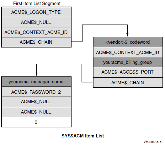
17.3.6. The ACM Communications Buffer and Itemset
For dialogue mode calls using Authenticate Principal or Change Password function codes, the SYS$ACM[W] may return a primary status of ACME$_OPINCOMPL, indicating more data is needed. In that case, a description of the data needed is provided within the ACM communications buffer pointed to from the ACM context argument longword you supplied.
Field ACMECB$L_ITEM_SET_COUNT indicates how many entries are in the itemset, while field ACMECB$PS_ITEM_SET points to an array of itemset entries.
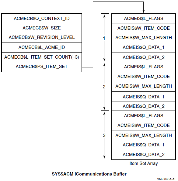
17.3.7. Itemset Entries
Within a single itemset entry, when the flag ACMEDLOGFLG$V_INPUT is set in field ACMEIS$L_FLAGS, the third field is called ACMEIS$W_MAX_LENGTH and indicates the maximum acceptable length in bytes for the input requested.
When the flag ACMEDLOGFLG$V_INPUT is clear, however, the third field is called ACMEIS$W_MSG_TYPE and indicates the message category of the output text. That category can be used to decide placement or presentation of output text for a user. Bit 14 of that code, like bit 13 of an item code, indicates that the data in question (output data in this case) is textual in nature and your program can handle it using methods appropriate for text.
No ACME agent will ever send an ACME-specific message category to an ACM without knowing that the ACM is familiar with that message category.
Because there is no ACMEIS$W_MSG_TYPE field when flag ACMEDLOGFLG$V_INPUT is set, the SYS$ACM[W] performs Unicode conversion of prompting information based on whether or not the resulting input data is eligible for Unicode conversion. Thus, it is not possible to have multiple text formats in prompts with the corresponding input.
17.3.8. Synchronization of Your System Service Calls
As with many other system services, you have your choice of the SYS$ACM or SYS$ACMW interface. Choose one or the other based on whether your program will be doing other work (authentication-related or otherwise) while the authentication operation is underway. This choice has only to do with synchronization within your program; it is unrelated to your choice of dialogue mode or nondialogue mode.
17.4. Authentication Techniques
Your ACM can call the SYS$ACM[W] to change a password, and the effect is the same as if SET PASSWORD had made the call.
Your ACM can call the SYS$ACM[W] to authenticate a user. Your authentication is audited and break-in evasion is checked in the ACME server process, just as for LOGINOUT.
Your program can call the SYS$ACM[W] to log an event or to query for information specific to a particular domain of interpretation (DOI). With the exception of the general ACM information described in Section 17.4.5.3: Looking Up DOI and ACME IDs, all use of the Event or Query function codes is specific to a DOI.
17.4.1. Nondialogue Mode Operation
The simplest form of call to the SYS$ACM[W] is the nondialogue mode call, illustrated in Figure 17.4, ''Nondialogue Mode Operation''. It resembles many other system services, except that the item list contains a wider variety of both input and output items.
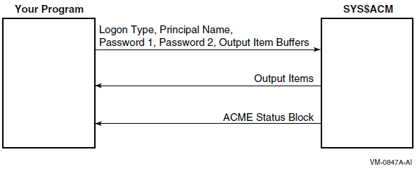
Use nondialogue mode when only a limited amount of interaction is possible, such as when an existing network protocol like FAL or FTP does not allow an arbitrary authentication exchange. Typically, such programs should specify an ACME$_LOGON_TYPE of ACME$K_NETWORK, indicating that while they supply a password, no complex interaction is possible.
17.4.2. Dialogue Mode Operation
Use dialogue mode when your ACM client program is flexible enough to respond to password change notification, to allow the user to answer arbitrary questions, such as the charge code for a session, and so on.
In dialogue mode, the SYS$ACM[W] uses the longword you provide by the ACM context argument parameter to store a pointer to an ACM communications buffer. Figure 17.5, ''Dialogue Mode'' illustrates dialogue mode operation.
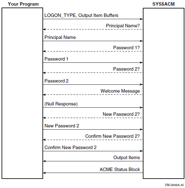
As with nondialogue mode, your ACM must provide on the initial call to the SYS$ACM[W] all output items and all input items that are not going to be the subject of an itemset entry.
Output itemset entries
The SYS$ACM[W] provides information for display to the user. The exact form of this display is up to your program, as guided by the message category provided in field ACMEIS$W_MSG_TYPE and by the item code provided in field ACMEIS$W_ITEM_CODE. Your program may in fact choose to ignore any or all output itemset entries, except for certain message category values that would not be appropriate, such as suppressing ACMEMC$K_SELECTION information that tells users about possible choices for their next input.
Input itemset entries
The SYS$ACM[W] provides information regarding input needed on the next call to the SYS$ACM[W]. In the simplest case, you can handle this by prompting a character cell terminal, using the prompt text provided in the itemset entry. For a more complex interface, some of the information sought might be provided by the program without user interaction, for instance if authentication were being done with the assistance of a smart card or other personalized hardware device.
If all of the itemset entries within the itemset were output itemset entries, your program should call the SYS$ACM[W] with an empty item list (containing just the terminator entry).
Dialogue mode operation applies only to the Authenticate Principal and Change Password functions. Calls to any other functions must be in nondialogue mode.
17.4.3. Login Categories and Classes
|
Login Category |
Login Class |
|---|---|
|
Interactive |
Local, Dialup, Remote |
|
Noninteractive |
Batch, Network |
Those login classes correspond to the values used in the ACME$_LOGON_TYPE item for the SYS$ACM[W]. Each may have specific policy requirements, and may be authenticated differently. Batch jobs, for example, start without specification of a password or other authentication information.
This choice can also influence authorization decisions, such as the VMS day and time restrictions.
Specifying item ACME$_LOGON_TYPE requires the IMPERSONATE privilege. It is defaulted to match the login class of the process that called the SYS$ACM[W].
| Login Type | Interaction Details |
|---|---|
|
Batch |
No authentication is involved. This may mean that credentials are not provided for certain domains of interpretation that base their credential creation on presentation of a password. |
|
Network |
Authentication is involved, but it operates in nondialogue mode unless an ACME agent (other than the VMS ACME agent) requires dialogue for authentication. |
|
Local, Dialup, and Remote |
Authentication is involved and further dialogue may be encountered to change expiring passwords, and so on. The SYS$ACM[W] expects a person to be available to answer questions raised through dialogue. |
Thus in the case of the local, dialup, or remote values for ACME$_LOGON_TYPE, you must provide an ACM context argument argument on all calls to the SYS$ACM[W] (and you must provide item ACME$_DIALOGUE_SUPPORT on the initial call to indicate support for input dialogue). With the network value for ACME$_LOGON_TYPE, those elements might be required with certain add-on ACME agents.
17.4.4. Principal Names
The ordering of ACME agents selected by the system manager
The syntax of the principal name
The spelling of the principal name
If the syntax provided to the SYS$ACM[W] can be handled by only one ACME agent, that settles the matter. If it can be handled by more than one ACME agent, then the decision also depends on which ACME agent (in order) is the first to be able to map the particular principal name to a VMS user name.
| Domain of Interpretation | Principal Name Syntax |
|---|---|
|
VMS |
username |
|
Windows NT |
domain\user OR user@domain OR user |
Given those two ACME agents, it is possible to specify a principal name that can only be handled by the Windows NT DOI (by a full specification including the execute (@) command), but it is not possible to specify a principal name that can only be handled by the VMS DOI.
But that table only describes the situation for the combination of those two ACME agents. The VMS ACME is always present on any OpenVMS system, but on some systems you might omit the NT ACME and/or include some other ACME agents, one of which might honor some of the same syntax as the NT ACME agent.
17.4.5. Targeting Your System Service Calls
Most Authenticate Principal and Change Password calls are handled by one or more ACME agents chosen in accordance with selection criteria set by the system manager.
ACME$_TARGET_DOI_ID
ACME$_TARGET_DOI_NAME
These item codes are used when your program requires that a particular DOI handle your request.
17.4.5.1. DOI Names
| Domain of Interpretation | Name | Source of the ACME Agent |
|---|---|---|
|
VMS |
VMS |
OpenVMS |
|
Windows NT |
MSV1_0 |
Advanced Server |
17.4.5.2. When to Use DOI_NAME vs. DOI_ID
ACME$_TARGET_DOI_ID
ACME$_TARGET_DOI_NAME
ACME$_CONTEXT_ACME_ID
ACME$_CONTEXT_ACME_NAME
The system manager specifies DOI names in configuring the ACME server, although in most cases the system manager uses the registered names specified by a vendor.
DOI IDs are implicitly specified by the system manager by the order in which each is specified for the first time after each boot of the system. That means that a particular DOI ID may have an entirely different meaning on the same machine after the next reboot.
Specifying a DOI_NAME clearly gives better ease-of-use, while specifying a DOI_ID gives slightly better performance with an overhead penalty paid upfront to look up a DOI_ID based on a DOI_NAME. Some programs that call the SYS$ACM[W], however, need to perform that lookup in order to interpret the contents of the ACM communications buffer, so in those cases the DOI_ID is already available and can be used in calls to the SYS$ACM[W].
17.4.5.3. Looking Up DOI and ACME IDs
Use the Query function code with a Target DOI ID of 0 (meaning the SYS$ACM[W] itself) to determine what DOI_ID corresponds to a given name.
- SYS$ACM[W] server query - ID value 0:
- ITMCOD = ACME$_TARGET_DOI_ID
- BUFSIZ = 4
- BUFADR = Address of longword containing 0
- Query based on ACME name:
- ITMCOD = ACME$_QUERY_KEY_TYPE
- BUFSIZ = 4
- BUFADR = Address of longword containing ACME$K_QUERY_ACME_NAME
- Specify ACME name:
- ITMCOD = ACME$_QUERY_KEY_VALUE
- BUFSIZ = Characters in ACME name (times 4 if setting ACME$M_UCS2_4)
- BUFADR = Address of buffer containing ACME name
- Specify ACME ID as the return value:
- ITMCOD = ACME$_QUERY_TYPE
- BUFSIZ = 4
- BUFADR = Address of longword containing ACME$K_QUERY_ACME_ID
- Specify the output buffer
- ITMCOD = ACME$_QUERY_DATA
- BUFSIZ = 4
- BUFADR = Address of longword to receive the ACME_ID
17.4.6. Determining ACME Information with the Query Function
ACME$_TARGET_DOI_ID (or ACME$_TARGET_DOI_NAME)
ACME$_QUERY_TYPE
ACME$_QUERY_KEY_TYPE
ACME$_QUERY_KEY_VALUE
Your program receives back the item ACME$_QUERY_DATA.
Semantics of those items and where the data comes from is entirely up to the ACME agent that you specify as the target of the Query function.
See the documentation for that ACME agent for more information.
17.4.7. Reporting an Event
ACME$_EVENT_TYPE
ACME$_EVENT_DATA_IN
Your program possibly receives back item ACME$_EVENT_DATA_OUT. Whether ACME$_EVENT_DATA_OUT is supported and the exact nature of what the SYS$ACM[W] is supposed to do for an event is up to the ACME agent that you specify as the target of the Event function.
See the documentation for that ACME agent for more information.
17.5. Authentication Scenarios
Authenticate a specified user.
Change a password.
Reauthenticate the current user.
Create a process on behalf of a user.
SYS$GETUAI
SYS$SETUAI
SYS$HASH_PASSWORD
SYS$SCAN_INTRUSION
Modal restriction enforcement (network, batch, interactive, and so on)
Checks for account disabled, account expired, and so on
These steps made it difficult to provide a complete and bug-free implementation. Furthermore, such an approach dealt only with traditional VMS password-based authentication rather than including add-on mechanisms. With the introduction of the SYS$ACM[W], those scenarios can be handled in a uniform, supported manner.
17.5.1. Simple User Authentication
LOCAL
STATUS,
ACME_STATUS_BLOCK : VECTOR [4,LONG],
NON_DIALOGUE_ITMLST : ALIAS_ON_AXP $ITMLST_DECL (ITEMS=2);
!
! Populate that item list
!
$ITMLST_INIT(ITMLST = NON_DIALOGUE_ITMLST,
!
! What is the Principal Name
!
(ITMCOD = ACME$_PRINCIPAL_NAME_IN,
BUFSIZ = %CHARCOUNT('JENKINS'),
BUFADR = UPLIT BYTE('JENKINS')),
!
! What Password was given to this routine ?
!
(ITMCOD = ACME$_PASSWORD_1,
BUFSIZ = .INPUT_STRING [DSC$W_LENGTH],
BUFADR = .INPUT_STRING [DSC$A_POINTER] ) );
!
! Now call the System Service
!
STATUS = $ACMW (EFN=EFN$C_ENF,
FUNC=ACME$_FC_AUTHENTICATE_PRINCIPAL,
ITMLST=NON_DIALOGUE_ITMLST,
ACMSB=ACME_STATUS_BLOCK );17.5.2. Evaluating Status Codes
After any call to the SYS$ACM[W], you must check the return status from the call and the return status in the ACM Status Block. Following is a sample check:
IF NOT .STATUS
THEN
SIGNAL_STOP ( STATUS );
IF NOT .ACME_STATUS_BLOCK [ACMESB$L_STATUS]
AND ( .ACME_STATUS_BLOCK [ACMESB$L_STATUS] NEQ ACME$_OPINCOMPL )
THEN
BEGIN
IF .ACME_STATUS_BLOCK [ACMESB$L_ACME_ID] NEQ 0
THEN
REPORT_ACME_SPECIFIC_ERROR ( ACME_STATUS_BLOCK )
ELSE
IF .ACME_STATUS_BLOCK [ACMESB$L_SECONDARY_STATUS]
EQL .ACME_STATUS_BLOCK [ACMESB$L_STATUS]
THEN
SIGNAL_STOP (
.ACME_STATUS_BLOCK [ACMESB$L_STATUS] )
ELSE
SIGNAL_STOP (
.ACME_STATUS_BLOCK [ACMESB$L_STATUS], 0,
.ACME_STATUS_BLOCK [ACMESB$L_SECONDARY_STATUS], 0 );
END;
The details of handling the field ACMESB$L_ACME_STATUS depend on the nature of the ACME agent indicated in field ACMESB$L_ACME_ID. If that ACME agent is not specifically known to the program that calls the SYS$ACM[W], there is no way to interpret that field. The previous example presumes there is special knowledge regarding at least one ACME agent held in routine REPORT_ACME_SPECIFIC_ERROR, which is not supplied.
17.5.3. Password Change Dialogue
Particularly with the function code ACME$_FC_CHANGE_PASSWORD, you cannot reliably predict all the necessary input at the time of the initial call, because the first password chosen might be found in the password history file or be unacceptable in some other way.
BIND
ACMECB = .CONTEXT : BLOCK[,BYTE],
ITEM_SET = .ACMECB[ACMECB$PS_ITEM_SET] : BLOCKVECTOR[,ACMEIS$K_LENGTH,BYTE],
RESPONSE_ITEM_COUNTER : INITIAL [0],
!
! A real program should calculate the size for the following
! by basing it on .ACMECB[ACMECB$L_ITEM_SET_COUNT].
!
RESPONSE_ITEM_LIST : ALIAS_ON_AXP $ITMLST_DECL (ITEMS=9999);
!
! Store a terminator in case there are no input items.
!
RESPONSE_ITEM_LIST [0,ITM$L_TERMINATOR] = 0;
!
! Iterate over Itemset Array
!
INCRU ITEM_SET_INDEX FROM 1 TO .ACMECB[ACMECB$L_ITEM_SET_COUNT] DO
BEGIN
BIND
ITEM_SET_ENTRY = ITEM_SET [.ITEM_SET_INDEX,0,0,0,0],
ITEM_FLAGS = ITEM_SET_ENTRY [ACMEIS$L_FLAGS] : BLOCK[4,BYTE],
ITEM_CODE = ITEM_SET_ENTRY [ACMEIS$W_ITEM_CODE] : BLOCK[2,BYTE];
IF NOT .ITEM_CODE[ACMEIC$V_UCS]
THEN
SIGNAL_STOP ( THIS_PROGRAM_HANDLES_ONLY_TEXT );
IF NOT .ITEM_CODE[ACMEIC$V_OUTPUT]
THEN
BEGIN ! Respond to an input item
!
! Call subroutines to read input and put it in the item list.
!
IF .ITEM_FLAGS[ACMEDLOGFLG$V_NOECHO]
THEN
!
! Read the input - Last parameter (if any) indicates the
! prompt
! to be used on a confirmation read. That confirmation must
! match the initial response before returning here.
!
CONSTRUCT_ITEM_NOECHO_FROM_TERMINAL (
RESPONSE_ITEM_LIST [.RESPONSE_ITEM_COUNTER,0,0,0,0],
.ITEM_SET_ENTRY [acmeis$w_max_length],
ITEM_SET_ENTRY [acmeis$q_data_1],
ITEM_SET_ENTRY [acmeis$q_data_2] )
ELSE
!
! Just read the input - Last parameter indicates a default
! that will be taken by SYS$ACM if a blank line is supplied.
!
CONSTRUCT_ITEM_FROM_TERMINAL (
RESPONSE_ITEM_LIST [.RESPONSE_ITEM_COUNTER,0,0,0,0],
.ITEM_SET_ENTRY [acmeis$w_max_length],
ITEM_SET_ENTRY [acmeis$q_data_1],
ITEM_SET_ENTRY [acmeis$q_data_2] );
!
! Advance past this item.
!
RESPONSE_ITEM_COUNTER = .RESPONSE_ITEM_COUNTER + 1;
!
! Store a terminator in case this was the last input item.
!
RESPONSE_ITEM_LIST [.RESPONSE_ITEM_COUNTER,ITM$L_TERMINATOR] = 0;
BEGIN
END;
!
! Now call the System Service again, with the same FUNC argument.
!
! If all the item set entries were for output, we send a null item list.
!
STATUS = $ACMW (EFN=EFN$C_ENF,
FUNC=ACME$_FC_CHANGE_PASSWORD,
CONTXT=CONTEXT,
ITMLST=RESPONSE_ITEM_LIST,
ACMSB=ACMESB );This example leaves the details of handling an optional confirmation prompt to the routine CONSTRUCT_ITEM_NOECHO_FROM_TERMINAL, which is not supplied. In addition, the code to process and display output items is not shown.
Confirmation prompts are more common in Change Password than in Authenticate Principal, but the program that calls SYS$ACM[W] should be prepared to handle them in either situation (that is, any time dialogue mode is used).
17.5.4. Reauthentication of Current User
LOCAL
STATUS,
ACME_STATUS_BLOCK : VECTOR [4,LONG],
NON_DIALOGUE_ITMLST : ALIAS_ON_AXP $ITMLST_DECL (ITEMS=1);
!
! Populate that item list
!
$ITMLST_INIT(ITMLST = NON_DIALOGUE_ITMLST,
!
! What Password was given to this routine ?
!
(ITMCOD = ACME$_PASSWORD_1,
BUFSIZ = .INPUT_STRING [DSC$W_LENGTH],
BUFADR = .INPUT_STRING [DSC$A_POINTER] ) );
!
! Now call the System Service
!
STATUS = $ACMW (EFN=EFN$C_ENF,
FUNC=ACME$_FC_AUTHENTICATE_PRINCIPAL
+ACME$M_DEFAULT_PRINCIPAL,
ITMLST=NON_DIALOGUE_ITMLST,
ACMSB=ACME_STATUS_BLOCK );17.5.5. Manipulating Personas
The following example is a slight variant on the example in Section 17.5.1, ''Simple User Authentication'':
LOCAL
STATUS,
OLD_PERSONA,
NEW_PERSONA,
ACME_STATUS_BLOCK : VECTOR [4,LONG],
NON_DIALOGUE_ITMLST : ALIAS_ON_AXP $ITMLST_DECL (ITEMS=3);
!
! Populate that item list
!
$ITMLST_INIT(ITMLST = NON_DIALOGUE_ITMLST,
!
! What is the Principal Name
!
(ITMCOD = ACME$_PRINCIPAL_NAME_IN,
BUFSIZ = %CHARCOUNT('JENKINS'),
BUFADR = UPLIT BYTE('JENKINS')),
!
! What Password was given to this routine ?
!
(ITMCOD = ACME$_PASSWORD_1,
BUFSIZ = .INPUT_STRING [DSC$W_LENGTH],
BUFADR = .INPUT_STRING [DSC$A_POINTER] ) ),
!
! Where do we want the new Persona ID ?
!
(ITMCOD = ACME$_PERSONA_HANDLE_OUT,
BUFADR = NEW_PERSONA ) );
!
! Now call the System Service
!
STATUS = $ACMW (EFN=EFN$C_ENF,
FUNC=ACME$_FC_AUTHENTICATE_PRINCIPAL
+ACME$M_ACQUIRE_CREDENTIALS,
ITMLST=NON_DIALOGUE_ITMLST,
ACMSB=ACME_STATUS_BLOCK );
CHECK_STATUS ( .STATUS );
CHECK_ACME_STATUS ( ACME_STATUS_BLOCK );
!
! Now assume the new Persona
!
STATUS = $PERSONA_ASSUME (PERSONA=NEW_PERSONA,
FLAGS=0,
previous=OLD_PERSONA);
!
This example does not use item code ACME$_PERSONA_HANDLE_IN. That is for manipulating the characteristics of an existing persona, which is not the objective of this example.
17.5.6. Using CREPRC on Behalf of a User
After authentication, you can use the SYS$ACM[W] system service to create a process on behalf of the user, with process quotas set according the values in SYSUAF, as in the following example:
LOCAL
STATUS,
OLD_PERSONA,
NEW_PERSONA,
PIDADR,
CREPRC_QUOTA : VECTOR [255,BYTE], ! hopefully long enough
ACME_STATUS_BLOCK : VECTOR [4,LONG],
NON_DIALOGUE_ITMLST : ALIAS_ON_AXP $ITMLST_DECL (ITEMS=4);
!
! Populate that item list
!
$ITMLST_INIT(ITMLST = NON_DIALOGUE_ITMLST,
!
! What is the Principal Name
!
(ITMCOD = ACME$_PRINCIPAL_NAME_IN,
BUFSIZ = %CHARCOUNT('JENKINS'),
BUFADR = UPLIT BYTE('JENKINS')),
!
! What Password was given to this routine ?
!
(ITMCOD = ACME$_PASSWORD_1,
BUFSIZ = .INPUT_STRING [DSC$W_LENGTH],
BUFADR = .INPUT_STRING [DSC$A_POINTER] ) ),
!
! Where do we want the new persona ID?
!
(ITMCOD = ACME$_PERSONA_HANDLE_OUT,
BUFADR = NEW_PERSONA),
!
! Where do we want quota requirements stored ?
!
(ITMCOD = ACMEVMS$_CREPRC_QUOTA,
BUFSIZ = %ALLOCATION(CREPRC_QUOTA),
BUFADR = CREPRC_QUOTA ) );
!
! Now call the System Service
!
STATUS = $ACMW (EFN=EFN$C_ENF,
FUNC=ACME$_FC_AUTHENTICATE_PRINCIPAL,
ITMLST=NON_DIALOGUE_ITMLST,
ACMSB=ACME_STATUS_BLOCK );
CHECK_STATUS ( .STATUS );
CHECK_ACME_STATUS ( ACME_STATUS_BLOCK );
!
! That routine just detected any buffer too short error
!
! Temporarily assume the new Persona
!
STATUS = $PERSONA_ASSUME (PERSONA=NEW_PERSONA,
FLAGS=0,
previous=OLD_PERSONA);
CHECK_STATUS ( .STATUS );
!
! Now create the process under that persona
!
STATUS = $CREPRC (PIDADR=PIDADR,
IMAGE=$DESCRIPTOR('SYS$SYSTEM:LOGINOUT'),
INPUT=$DESCRIPTOR('TXA3:'),
OUTPUT=$DESCRIPTOR('TXA3:'),
ERROR=$DESCRIPTOR('TXA3:'),
QUOTA=CREPRC_QUOTA,
STSFLG=PRC$M_NOUAF+PRC$M_INHERIT_PERSONA);
CHECK_STATUS ( .STATUS );
!
! Revert to our old Persona
!
STATUS = $PERSONA_ASSUME (PERSONA=OLD_PERSONA);
CHECK_STATUS ( .STATUS );
!
! Delete the new persona from this process
!
STATUS = $PERSONA_DELETE (PERSONA=NEW_PERSONA );
CHECK_STATUS ( .STATUS );
!
The PRC$M_NOUAF flag prevents LOGINOUT from modifying process quotas, while the PRC$M_INHERIT_PERSONA prevents LOGINOUT from modifying the process persona, allowing use of the persona (and persona extension) of the parent process. The main purpose of LOGINOUT in this case becomes setting up the DCL environment.
17.6. Authentication Examples
This section provides two complete examples of using the SYS$ACM[W] system service. In addition to these examples, a utility program called ACMEUTIL is available for issuing authentication and change-password SYS$ACM system service calls and examining the results in both dialogue and nondialogue mode.
$acme auth/dial=(input,noecho)See the comments in ACMEUTIL_SETUP.COM for additional information on ACMEUTIL DCL syntax and capabilities.
ACMEUTIL is located in the SYS$EXAMPLES directory and is built by running the ACMEUTIL.COM procedure. To define the DCL verb ACMEUTIL, run the ACMEUTIL_SETUP.COM procedure.
17.6.1. Example Using Nondialogue Mode (C)
| Line | Activity | Special Notes |
|---|---|---|
|
45 |
Declare local storage |
This subroutine avoids static storage. |
|
105 |
Determine MAXBUF |
MAXBUF limits hardware interaction. |
|
105 |
Determine MAXBUF |
MAXBUF limits hardware interaction. |
|
158 |
Prepare a SYS$ACM item list |
We will add data as we go. |
|
210 |
Prepare to use the badge reader |
Subsequent steps use it. |
|
233 |
Compare DNA |
Invoking a hardware function. |
|
264 |
Read the principal name |
Data from the badge reader. |
|
298 |
Read the primary password |
Data from the badge reader. |
|
324 |
Read the secondary password |
Data from the badge reader. |
|
357 |
Free the badge reader |
We do not know when image will exit. |
|
372 |
Call SYS$ACMW |
Here is where we authenticate. |
|
389 |
Return status to our caller |
We choose to provide no details. |
1 #pragma module ACM_BADGE "V1.0" 2 /* 3 ** ACM_BADGE.C 4 */ 5 #define __NEW_STARLET 1 6 7 #include <string> // NULL and memset 8 #include <starlet.h> // for calling SYS$ACM 9 #include <iledef.h> // Item Lists 10 #include <iodef.h> // for calling $QIO 11 #include <iosbdef.h> // IO status blocks 12 #include <stsdef> // decoding status code fields 13 #include <efndef> // For event flag number definitions 14 #include <descrip.h> // for descriptor definitions 15 #include <utcblkdef.h> // required for acmedef.h 16 #include <acmedef.h> // ACME codes 17 #include <syidef.h> // GETSYI codes 18 19 /* 20 ** ACM_BADGE 21 ** 22 ** This subroutine obtains a user name and password from a 23 ** hardware badge reader and passes them in a nondialogue call to 24 ** SYS$ACM for evaluation. It returns success or failure status 25 ** to its caller. 26 ** 27 ** Obviously the hardware badge reader construction must be secure 28 ** enough to never divulge the password without validating a DNA 29 ** sample from the person who places the badge in the reader, 30 ** and that is why this is just a code sample in SYS$EXAMPLES: 31 ** rather than something that comes with a real hardware product. 32 ** 33 ** Arguments: 34 ** 35 ** None. 36 ** 37 ** Return values: 38 ** 39 ** ACME$_NORMAL - authentic 40 ** ACME$_AUTHFAILURE - not authentic 41 ** anything else - processing failure 42 */ 43 int ACM_BADGE() 44 { 45 int RetStatus; 46 int DasStatus; 47 char devnam[5]="BRA0:"; 48 struct dsc$descriptor_s devnam_desc = { 0, // length 49 DSC$K_DTYPE_T, // type 50 DSC$K_CLASS_S, // class 51 0}; // buf address 52 IOSB iosb; 53 ACMESB acmsb; 54 unsigned short int badge_reader_channel; 55 int logon_type = ACME$K_NETWORK; 56 int maxbuf; 57 int read_size; 58 59 /* 60 ** We will call SYS$ACM with multiple entries in an item list. 61 */ 62 enum acm_items 63 { 64 acm_logon_type, 65 acm_principal_name_in, 66 acm_password_1, 67 acm_password_2, 68 acm_terminator 69 }; 70 ILE3 acm_itmlst[acm_terminator+1]; 71 enum getsyi_items 72 { 73 getsyi_maxbuf, 74 getsyi_terminator 75 }; 76 ILE3 getsyi_itmlst[getsyi_terminator+1]; 77 78 /* 79 ** Our badge reader might provide very long input items, 80 ** because a user does not have to type them. Internally 81 ** the items will be carried in Unicode format, so the 82 ** length limit imposed by the 16-bit length field is 83 ** 1/4 of what one might first expect. 84 ** 85 ** Internal limits on the size of a single SYS$ACM request 86 ** actually constrain the total of all items to this size, 87 ** but we cannot predict how imbalanced the item lengths 88 ** will be, so we make all buffers be this maximum size. 89 ** 90 ** Depending on the value of system parameter MAXBUF, this 91 ** subroutine may try to read as many as buffer_size bytes 92 ** from the badge reader, so the Buffered IO Byte Limit 93 ** quota should be as large as buffer_size if the badge 94 ** reader is not a Direct IO device. 95 */ 96 enum sizes 97 { 98 buffer_size = 65535/4 99 }; 100 char principal_name_in[buffer_size]; 101 char password_1[buffer_size]; 102 char password_2[buffer_size]; 103 104 105 /* 106 ** Get the SYS$GETSYI item list ready. First zero it out, then fill it 107 in */ 108 memset ( // clear out memory 109 getsyi_itmlst, // - Address to write to 110 0, // - Character to fill 111 sizeof (getsyi_itmlst)); // - size to fill 112 113 /* 114 ** System Parameter MAXBUF constrains the size of Buffered IO 115 ** 116 ** Buffer maxbuf will be filled in by SYS$GETSYI. 117 */ 118 getsyi_itmlst[getsyi_maxbuf].ile3$w_code = SYI$_MAXBUF; 119 getsyi_itmlst[getsyi_maxbuf].ile3$w_length = sizeof (maxbuf); 120 getsyi_itmlst[getsyi_maxbuf].ile3$ps_bufaddr = &maxbuf; 121 getsyi_itmlst[getsyi_maxbuf].ile3$ps_retlen_addr = NULL; 122 123 /* 124 ** End the item list with a terminator 125 */ 126 getsyi_itmlst[getsyi_terminator].ile3$w_code = 0; 127 getsyi_itmlst[getsyi_terminator].ile3$w_length = 0; 128 getsyi_itmlst[getsyi_terminator].ile3$ps_bufaddr = NULL; 129 getsyi_itmlst[getsyi_terminator].ile3$ps_retlen_addr = NULL; 130 131 RetStatus = sys$getsyiw ( 132 EFN$C_ENF, /* no event flag */ 133 NULL, /* CSID address */ 134 NULL, /* Node Name */ 135 &getsyi_itmlst, /* Item List */ 136 &iosb, /* IO Status block */ 137 NULL, /* AST routine */ 138 0 ); /* AST Parameter */ 139 if (RetStatus & STS$M_SUCCESS) 140 { 141 /* 142 ** We use the smaller of maxbuf or the buffer size 143 */ 144 if (maxbuf < buffer_size) 145 { 146 read_size = maxbuf; 147 } 148 else 149 { 150 read_size = buffer_size; 151 } 152 } 153 else 154 { 155 return RetStatus; 156 } 157 158 /* 159 ** Get the SYS$ACM item list ready. First zero it out, then fill it 160 in. */ 161 memset ( // clear out memory 162 acm_itmlst, // - Address to write to 163 0, // - Character to fill 164 sizeof (acm_itmlst)); // - size to fill 165 166 /* 167 ** Buffer logon_type contains a constant ACME$K_NETWORK. 168 ** 169 ** Using an interactive Logon Type would subject us to password 170 ** change requests, which are not viable in nondialogue mode (or 171 ** from our hypothetical badge reader, for that matter). 172 */ 173 acm_itmlst[acm_logon_type].ile3$w_code = ACME$_LOGON_TYPE; 174 acm_itmlst[acm_logon_type].ile3$w_length = sizeof (logon_type); 175 acm_itmlst[acm_logon_type].ile3$ps_bufaddr = &logon_type; 176 acm_itmlst[acm_logon_type].ile3$ps_retlen_addr = NULL; 177 178 /* 179 ** Buffer principal_name_in will be filled in from the badge reader. 180 */ 181 acm_itmlst[acm_principal_name_in].ile3$w_code = ACME$_PRINCIPAL_NAME_IN; 182 acm_itmlst[acm_principal_name_in].ile3$w_length = maxbuf; 183 acm_itmlst[acm_principal_name_in].ile3$ps_bufaddr = &principal_name_in; 184 acm_itmlst[acm_principal_name_in].ile3$ps_retlen_addr = NULL; 185 186 /* 187 ** Buffer password_1 will be filled in from the badge reader. 188 */ 189 acm_itmlst[acm_password_1].ile3$w_code = ACME$_PASSWORD_1; 190 acm_itmlst[acm_password_1].ile3$w_length = maxbuf; 191 acm_itmlst[acm_password_1].ile3$ps_bufaddr = &password_1; 192 acm_itmlst[acm_password_1].ile3$ps_retlen_addr = NULL; 193 194 /* 195 ** Buffer password_2 will be filled in from the badge reader. 196 */ 197 acm_itmlst[acm_password_2].ile3$w_code = ACME$_PASSWORD_2; 198 acm_itmlst[acm_password_2].ile3$w_length = maxbuf; 199 acm_itmlst[acm_password_2].ile3$ps_bufaddr = &password_2; 200 acm_itmlst[acm_password_2].ile3$ps_retlen_addr = NULL; 201 202 /* 203 ** End the item list with a terminator 204 */ 205 acm_itmlst[acm_terminator].ile3$w_code = 0; 206 acm_itmlst[acm_terminator].ile3$w_length = 0; 207 acm_itmlst[acm_terminator].ile3$ps_bufaddr = NULL; 208 acm_itmlst[acm_terminator].ile3$ps_retlen_addr = NULL; 209 210 /* 211 ** Assign a channel to the Badge Reader. 212 */ 213 214 devnam_desc.dsc$w_length = sizeof(devnam); 215 devnam_desc.dsc$a_pointer = &devnam[0]; 216 RetStatus = sys$assign ( 217 &devnam_desc, /* Device Name */ 218 &badge_reader_channel, /* channel to badge reader */ 219 0, /* access mode */ 220 0 ); /* Mailbox Name */ 221 if (!(RetStatus & STS$M_SUCCESS)) 222 { 223 return RetStatus; 224 } 225 226 /* 227 ** Exit from this one pass loop to deassign the channel and return. 228 */ 229 230 do 231 { 232 233 /* 234 ** Have the reader compare DNA. 235 ** 236 ** A failed DNA comparison from the hardware is reported 237 ** to the user the same as any other authentication failure, 238 ** withholding details regarding what went wrong. 239 */ 240 241 RetStatus = sys$qiow ( 242 EFN$C_ENF, /* no event flag */ 243 badge_reader_channel, /* channel to badge reader */ 244 IO$_ACCESS, /* IO function code */ 245 &iosb, /* IO Status block */ 246 NULL, /* AST routine */ 247 0, /* AST Parameter */ 248 0, /* p1 */ 249 0, /* p2 */ 250 0, /* p3 */ 251 0, /* p4 */ 252 0, /* p5 */ 253 0 ); /* p6 */ 254 if (RetStatus & STS$M_SUCCESS) 255 { 256 RetStatus = iosb.iosb$w_status; 257 } 258 if (!(RetStatus & STS$M_SUCCESS)) 259 { 260 RetStatus = ACME$_AUTHFAILURE; /* hide the exact cause */ 261 continue; /* exit from the do loop */ 262 } 263 264 /* 265 ** Read the Principal Name. 266 */ 267 268 RetStatus = sys$qiow ( 269 EFN$C_ENF, /* no event flag */ 270 badge_reader_channel, /* channel to badge reader */ 271 IO$_READVBLK, /* IO function code */ 272 &iosb, /* IO Status block */ 273 NULL, /* AST routine */ 274 0, /* AST Parameter */ 275 &principal_name_in, /* Buffer address */ 276 read_size, /* Buffer length */ 277 0, /* p3 */ 278 0, /* p4 */ 279 0, /* p5 */ 280 0 ); /* p6 */ 281 if (RetStatus & STS$M_SUCCESS) 282 { 283 RetStatus = iosb.iosb$w_status; 284 } 285 if (RetStatus & STS$M_SUCCESS) 286 { 287 acm_itmlst[acm_principal_name_in].ile3$w_length = iosb.iosb$w_bcnt; 288 } 289 else 290 { 291 continue; /* exit from the do loop */ 292 } 293 294 /* 295 ** Read the Primary Password. 296 */ 297 298 RetStatus = sys$qiow ( 299 EFN$C_ENF, /* no event flag */ 300 badge_reader_channel, /* channel to badge reader */ 301 IO$_READVBLK, /* IO function code */ 302 &iosb, /* IO Status block */ 303 NULL, /* AST routine */ 304 0, /* AST Parameter */ 305 &password_1, /* Buffer address */ 306 read_size, /* Buffer length */ 307 0, /* p3 */ 308 0, /* p4 */ 309 0, /* p5 */ 310 0 ); /* p6 */ 311 if (RetStatus & ) 312 { 313 RetStatus = iosb.iosb$w_status; 314 } 315 if (RetStatus & STS$M_SUCCESS) 316 { 317 acm_itmlst[acm_password_1].ile3$w_length = iosb.iosb$w_bcnt; 318 } 319 else 320 { 321 continue; /* exit from the do loop */ 322 } 323 324 /* 325 ** Read the Secondary Password. 326 */ 327 328 RetStatus = sys$qiow ( 329 EFN$C_ENF, /* no event flag */ 330 badge_reader_channel, /* channel to badge reader */ 331 IO$_READVBLK, /* IO function code */ 332 &iosb, /* IO Status block */ 333 NULL, /* AST routine */ 334 0, /* AST Parameter */ 335 &password_2, /* Buffer address */ 336 read_size, /* Buffer length */ 337 0, /* p3 */ 338 0, /* p4 */ 339 0, /* p5 */ 340 0 ); /* p6 */ 341 if (RetStatus & STS$M_SUCCESS) 342 { 343 RetStatus = iosb.iosb$w_status; 344 } 345 if (RetStatus & STS$M_SUCCESS) 346 { 347 acm_itmlst[acm_password_2].ile3$w_length = iosb.iosb$w_bcnt; 348 } 349 else 350 { 351 continue; /* exit from the do loop */ 352 } 353 354 } 355 while (1 == 2); 356 357 /* 358 ** Deassign the channel to the Badge Reader. 359 */ 360 361 DasStatus = sys$dassgn ( 362 badge_reader_channel ); /* channel to badge reader */ 363 if (RetStatus & STS$M_SUCCESS) 364 { 365 RetStatus = DasStatus; 366 } 367 if (!(RetStatus & STS$M_SUCCESS)) 368 { 369 return RetStatus; 370 } 371 372 /* 373 ** Attempt authentication. 374 */ 375 376 RetStatus = sys$acmw ( 377 EFN$C_ENF, /* no event flag */ 378 ACME$_FC_AUTHENTICATE_PRINCIPAL, /* ACM function code */ 379 NULL, /* pointer to Context pointer */ 380 &acm_itmlst, /* Item List */ 381 &acmsb, /* ACM Status block */ 382 NULL, /* AST routine */ 383 0 ); /* AST Parameter */ 384 if (RetStatus & STS$M_SUCCESS) 385 { 386 RetStatus = acmsb.acmesb$l_status; 387 } 388 389 return RetStatus; // return with ACM status 390 }
17.6.2. Example Using Dialogue Mode (Pascal)
This more complex example can respond to an arbitrary itemset provided in the ACM communications buffer by successive calls to the SYS$ACM[W].In particular, the item list allocated to respond to a given itemset is automatically made large enough to respond to each possible itemset entry if it happens to be an input itemset entry. This differs from the programming tactic used in Section 17.5.3, ''Password Change Dialogue'' because variable sizing of automatic (stack) variables is available in Pascal but not in BLISS.
| Line | Activity | Special Notes |
|---|---|---|
|
22 |
Function AUTHENTICATE |
Called by one line at the very end. |
|
180 |
Function RESPOND |
Provide input requested by SYS$ACM[W]. |
|
239 |
Function RECURSE_OVER_ITEMS |
Mandatory specification of attributes. Handle one possible input and many possible output entries. |
|
276 |
Procedure WRITE_ITEM_PLAIN |
Write to the terminal. |
|
298 |
Procedure SET_BUFFER |
Use input code rather than reading terminal. |
|
321 |
Fail on non-text other than FINGERPRINT_READIT |
No ACME should request any other non-text. |
|
358 |
Read a fingerprint |
Use the hardware. |
|
438 |
Synthesize principal name |
Call SET_BUFFER with the proper string. |
|
496 |
Prompt the user for other text |
If any ACME agent requests prompt, it may do so; other ACME agents may request additional information. |
|
587 |
Fill in the item list |
Store input text. |
|
608 |
Process output item set entries |
Send output text to the terminal. |
|
750 |
Call SYS$ACM with response |
When recursion is done, send it. |
|
761 |
Make the initial call to RECURSE_OVER_ITEMS |
Initialize for this iteration and start recursion. |
|
775 |
Learn the ACME_ID of the fingerprint ACME |
ACME-specific item codes are specific to an ACME. |
|
805 |
Make an initial SYS$ACMW call |
Start with invariant information. |
|
828 |
Loop calling RESPOND |
So long as the status is ACME$_OPINCOMPL. |
|
863 |
Close channels |
Clean-up of open channels. |
|
885 |
Return status to caller |
Failures exited earlier. |
2 'sys$Library:PASCAL$LIB_ROUTINES')] 3 PROGRAM ACM_SHOPFLOOR(OUTPUT); 4 { } 5 { AUTHENTICATE - major subroutine of this module } 6 { } 7 { This function is called with a USER_INDEX, indicating which } 8 { of 10 buttons on the shop floor kiosk was pushed, and thus } 9 { which of ten employees is to be authenticated. } 10 { } 11 TYPE PRINCIPAL_INDEX_TYPE = ( 12 PRINCIPAL_1, 13 PRINCIPAL_2, 14 PRINCIPAL_3, 15 PRINCIPAL_4, 16 PRINCIPAL_5, 17 PRINCIPAL_6, 18 PRINCIPAL_7, 19 PRINCIPAL_8, 20 PRINCIPAL_9, 21 PRINCIPAL_10 ); 22 { } 23 { This subroutine translates each of the 10 possible index } 24 { values into one of ten generic principal names. To avoid } 25 { changes to this client program, those principal names are } 26 { mapped into the principal names actually corresponding to } 27 { individual names within the ACME Server, so that a single } 28 { data file can be modified by a designated administrator } 29 { without changing the client software. } 30 { } 31 { } 32 { After the Principal Name has been determined, the user must } 33 { be authenticated. At some kiosks there is a fingerprint } 34 { reader that will be used for authentication, while at the } 35 { spray painting station a keyboard is always used because } 36 { employees are wearing rubber gloves. For some sensitive } 37 { combinations of Principal Name and kiosk, a fingerprint } 38 { and passwords might both be required. These variations, } 39 { however, are determined by ACMEs within the ACME Server, } 40 { and this client code merely authenticates using whatever } 41 { method might be specified in the Context Area returned by } 42 { successive SYS$ACM calls. } 43 { } 44 CONST 45 FINGERPRINT_READIT = 32770; { from the Fingerprint ACME } 46 { } 47 { After authentication it is also possible that password } 48 { expirations may need to be handled, in which case even in } 49 { situations where a fingerprint would normally be sufficient,} 50 { the user will actually have to engage in typing. Whether } 51 { users who normally authenticate with a fingerprint even } 52 { have a password is an administrative issue enforced by } 53 { configuration of the ACMEs. As in the authentication step, } 54 { this client software just implements whatever mechanism is } 55 { specified in the Context Area returned by successive } 56 { SYS$ACM calls. } 57 { } 58 FUNCTION AUTHENTICATE ( PRINCIPAL_INDEX : PRINCIPAL_INDEX_TYPE ):BOOLEAN; 59 TYPE 60 ACMECB_PTR = ^ACMECB$TYPE; 61 CHANNEL_TYPE = [WORD] 0..65535; 62 VAR 63 FINGERPRINT_READER_CHANNEL : CHANNEL_TYPE VALUE 0; 64 TERMINAL_CHANNEL : CHANNEL_TYPE VALUE 0; 65 MY_LOGON_TYPE : INTEGER VALUE ACME$K_LOCAL; 66 MY_DIALOGUE_SUPPORT : INTEGER 67 VALUE ACMEDLOGFLG$M_INPUT + ACMEDLOGFLG$M_NOECHO; 68 { } 69 { We rely on an initial query to determine the ACME ID } 70 { of the Fingerprint ACME in the current running system. } 71 { We use that ACME ID to compare against ACMECB$L_ACME_ID } 72 { in the ACME Communications Buffer to determine whether } 73 { an ACME-specific input item set is one created by the } 74 { Fingerprint ACME, because ACME-specific item codes must } 75 { qualified by the originating ACME. } 76 { } 77 { Field ACMECB$L_ACME_ID.ACMEID$V_ACME_NUM will be the } 78 { actual basis of comparison, because it is sufficient to } 79 { identify a particular ACME and the other fields within } 80 { an ACME ID might change between when our query call } 81 { completes and when we make our authenticate call. } 82 { } 83 { We make our query against the reserved ID value of 0, } 84 { to gather information about the ACME Agents. This query } 85 { is actually handled by the SYS$ACMW system service. } 86 { } 87 { Data elements for the query for ACME ID } 88 { } 89 { Addresses of these elements will be set into item list } 90 { ACM_QUERY_ITMLST by procedural code below. } 91 { } 92 SYS$ACM_ACME_ID : INTEGER VALUE 0; 93 ACME_QUERY_ACME_NAME : INTEGER VALUE ACME$K_QUERY_ACME_NAME; 94 FINGERPRINT_ACME_NAME : STRING(16) VALUE 'FINGERPRINT_ACME'; 95 ACME_TARGET_DOI_ID : INTEGER VALUE ACME$K_QUERY_ACME_ID; 96 FINGERPRINT_ACME_ID : ACMEID$TYPE; 97 { } 98 { Item list for the Query } 99 { } 100 ACM_QUERY_ITMLST : ARRAY[0..5] OF ILE3$TYPE 101 VALUE [ 0:[ILE3$W_LENGTH:4; 102 ILE3$W_CODE:ACME$_TARGET_DOI_ID; 103 ILE3$PS_BUFADDR:0; 104 ILE3$PS_RETLEN_ADDR:NIL]; 105 1:[ILE3$W_LENGTH:4; 106 ILE3$W_CODE:ACME$_QUERY_KEY_TYPE; 107 ILE3$PS_BUFADDR:0; 108 ILE3$PS_RETLEN_ADDR:NIL]; 109 2:[ILE3$W_LENGTH:16; 110 ILE3$W_CODE:ACME$_QUERY_KEY_VALUE; 111 ILE3$PS_BUFADDR:0; 112 ILE3$PS_RETLEN_ADDR:NIL]; 113 3:[ILE3$W_LENGTH:4; 114 ILE3$W_CODE:ACME$_QUERY_TYPE; 115 ILE3$PS_BUFADDR:0; 116 ILE3$PS_RETLEN_ADDR:NIL]; 117 4:[ILE3$W_LENGTH:4; 118 ILE3$W_CODE:ACME$_QUERY_DATA; 119 ILE3$PS_BUFADDR:0; 120 ILE3$PS_RETLEN_ADDR:NIL]; 121 5:[ILE3$W_LENGTH:0; 122 ILE3$W_CODE:0; 123 ILE3$PS_BUFADDR:0; 124 ILE3$PS_RETLEN_ADDR:NIL]]; 125 { } 126 { Item list for initial Authentication call } 127 { } 128 MY_ACM_ITMLST_A : ARRAY[0..2] OF ILE3$TYPE 129 VALUE [ 0:[ILE3$W_LENGTH:4; 130 ILE3$W_CODE:ACME$_LOGON_TYPE; 131 ILE3$PS_BUFADDR:0; 132 ILE3$PS_RETLEN_ADDR:NIL]; 133 1:[ILE3$W_LENGTH:4; 134 ILE3$W_CODE:ACME$_DIALOGUE_SUPPORT; 135 ILE3$PS_BUFADDR:0; 136 ILE3$PS_RETLEN_ADDR:NIL]; 137 2:[ILE3$W_LENGTH:0; 138 ILE3$W_CODE:0; 139 ILE3$PS_BUFADDR:0; 140 ILE3$PS_RETLEN_ADDR:NIL]]; 141 { } 142 { Variables used both inside and outside Function RESPOND } 143 { } 144 MY_ACMESB : ACMESB$TYPE; 145 MY_CONTXT : ACMECB_PTR; 146 MY_STATUS : UNSIGNED; 147 TRASH_STATUS : UNSIGNED; 148 { } 149 { The ITEMSET array we will read } 150 { } 151 TYPE 152 { } 153 { A string longer than we will ever see, defined to } 154 { avoid exceeding Pascal's 2**16-1 limit on string } 155 { length. } 156 { } 157 CHAR_ARRAY_TYPE = PACKED ARRAY [1..65535] 158 OF CHAR; 159 CHAR_ARRAY_TYPE_POINTER = ^CHAR_ARRAY_TYPE; 160 { } 161 { An array longer than we will ever see, defined to } 162 { avoid: } 163 { } 164 { "%PASCAL-E-SIZGTRMAX, Size exceeds MAXINT bits". } 165 { } 166 ITEMSET_ARRAY_TYPE = 167 PACKED ARRAY [1..MAXINT DIV (ACMEIS$K_LENGTH*8)] 168 OF ACMEITMSET$TYPE; 169 ITEMSET_ARRAY_TYPE_POINTER = ^ITEMSET_ARRAY_TYPE; 170 VAR 171 ITEMSET_ARRAY : ITEMSET_ARRAY_TYPE_POINTER; 172 { } 173 { A special declaration is required in order to } 174 { Synchronize on an ACM Status Block } 175 { } 176 [ASYNCHRONOUS,EXTERNAL(SYS$SYNCH)] FUNCTION $SYNCH_ACMESB ( 177 %IMMED EFN : UNSIGNED := %IMMED 0; 178 VAR IOSB : [VOLATILE] ACMESB$TYPE := %IMMED 0) 179 : INTEGER; EXTERNAL; 180 { } 181 { Function to fill in responses to input itemsets } 182 { } 183 { Input itemsets will require buffer space, and } 184 { although each input itemset will use no more } 185 { than 65535 bytes, the number of input itemsets } 186 { provided in a single dialogue step is not } 187 { bounded. } 188 { } 189 { Therefore we invoke this function recursively } 190 { each time we encounter an input itemset, } 191 { making use of a conformant parameter to } 192 { allocate the appropriate length buffer. When } 193 { all itemsets have been processed, we make our } 194 { continuation call to $ACM from the deepest } 195 { level of recursion (when all buffers are still } 196 { intact), and then return from function RESPOND } 197 { entirely to wait for completion of the call. } 198 { } 199 { This recursive approach using stack-based } 200 { buffers is fine for operation on the expandable } 201 { main VMS user-mode stack, but an application } 202 { operating on non-expandable stacks, such as } 203 { non-initial stack from VAX Ada or DECthreads, } 204 { should obviously use iteration and heap-based } 205 { explicit allocation instead. } 206 { } 207 FUNCTION RESPOND ( ITEMSET_COUNT : INTEGER ):INTEGER; 208 { } 209 { The Item List we will write for use on the } 210 { next call to SYS$ACM will never have more } 211 { entries than the Itemset List we received } 212 { in the ACM Communications Buffer from the } 213 { previous call to SYS$ACM, so we choose that } 214 { maximum size for our item list. } 215 { } 216 TYPE 217 ITEM_LIST_TEMPLATE ( UPPER_BOUND : INTEGER ) 218 = ARRAY [1..UPPER_BOUND] OF ILE3$TYPE; 219 VAR 220 ITEM_LIST : ITEM_LIST_TEMPLATE ( ITEMSET_COUNT + 1 ); 221 EACH_ITEM : INTEGER VALUE 1; 222 { } 223 { Each invocation of RECURSE_OVER_ITEMS will } 224 { allocate an automatic (stack-based) buffer. } 225 { } 226 TYPE 227 INPUT_BUFFER_TEMPLATE ( MAX_SIZE : INTEGER ) 228 = PACKED ARRAY [1..MAX_SIZE] OF CHAR; 229 { } 230 { Variables for parsing the Itemset List } 231 { } 232 VAR 233 CHAR_ARRAY_LENGTH_1 : INTEGER; 234 CHAR_ARRAY_POINTER_1 : CHAR_ARRAY_TYPE_POINTER; 235 CHAR_ARRAY_LENGTH_2 : INTEGER; 236 CHAR_ARRAY_POINTER_2 : CHAR_ARRAY_TYPE_POINTER; 237 EACH_ITEMSET : INTEGER VALUE 1; 238 INPUT_IOSB, CONFIRM_IOSB : IOSB$TYPE; 239 { } 240 { RECURSE_OVER_ITEMS } 241 { } 242 { This function gets called: } 243 { } 244 { 1. Once with a parameter of zero at the } 245 { start of processing an Itemset List. } 246 { } 247 { 2. Recursively as each input itemset is } 248 { encountered in the Itemset List. } 249 { } 250 { Multiple output itemsets are processed at a } 251 { single recursion level until the end of the } 252 { Itemset List or until an input itemset } 253 { is found. } 254 FUNCTION RECURSE_OVER_ITEMS ( MAX_SIZE : INTEGER ):INTEGER; 255 { } 256 { The buffer we will use for this input item } 257 { } 258 { The INPUT_BUFFER lifetime needs only be for } 259 { the lifetime of RECURSE_OVER_ITEMS because it } 260 { is filled by SYS$QIOW at this recursion } 261 { level and provided as input to SYS$ACM at } 262 { the innermost recursion level. } 263 { } 264 VAR 265 { } 266 { We use MAX_SIZE+1 to avoid the error: } 267 { } 268 { %PAS-F-LOWGTRHIGH, low-bound exceeds high-bound } 269 { } 270 { when MAX_SIZE is 0. } 271 { } 272 INPUT_BUFFER : INPUT_BUFFER_TEMPLATE ( MAX_SIZE+1 ); 273 CONFIRM_BUFFER : INPUT_BUFFER_TEMPLATE ( MAX_SIZE+1 ); 274 QIO_FUNC : INTEGER; 275 { } 276 PROCEDURE WRITE_ITEM_PLAIN; 277 BEGIN { WRITE_ITEM_PLAIN } 278 IF CHAR_ARRAY_POINTER_1 <> NIL 279 THEN 280 IF CHAR_ARRAY_LENGTH_1 = 0 281 THEN 282 WRITELN 283 ELSE 284 WRITELN ( 285 CHAR_ARRAY_POINTER_1^[1.. 286 CHAR_ARRAY_LENGTH_1] ); 287 IF CHAR_ARRAY_POINTER_2 <> NIL 288 THEN 289 IF CHAR_ARRAY_LENGTH_2 = 0 290 THEN 291 WRITELN 292 ELSE 293 WRITELN ( 294 CHAR_ARRAY_POINTER_2^[1.. 295 CHAR_ARRAY_LENGTH_2] ); 296 END; { WRITE_ITEM_PLAIN } 297 { } 298 PROCEDURE SET_BUFFER ( 299 PRINCIPAL_NAME : STRING ); 300 BEGIN { PROCEDURE SET_BUFFER } 301 INPUT_IOSB.IOSB$W_BCNT := 302 MIN ( SIZE ( PRINCIPAL_NAME ), 303 SIZE ( INPUT_BUFFER ) ); 304 { } 305 { The following line will produce a } 306 { Pascal run-time error if SYS$ACM does } 307 { not specify input lengths of at least } 308 { 12 characters. } 309 { } 310 READV ( PRINCIPAL_NAME, INPUT_BUFFER ); 311 { } 312 END; { PROCEDURE SET_BUFFER } 313 { } 314 BEGIN { FUNCTION RECURSE_OVER_ITEMS } 315 { } 316 { Process any initial Input Itemset } 317 { } 318 IF MAX_SIZE <> 0 319 THEN 320 BEGIN { process Input Itemset } 321 { } 322 { First we consider non-text ACME-specific } 323 { item codes, and the only one of those we } 324 { are prepared to handle is the Fingerprint } 325 { ACME code FINGERPRINT_READIT. } 326 { } 327 IF ITEMSET_ARRAY^[EACH_ITEMSET] 328 .ACMEIS$W_ITEM_CODE.ACMEIC$V_ACME_SPECIFIC 329 AND NOT ITEMSET_ARRAY^[EACH_ITEMSET] 330 .ACMEIS$W_ITEM_CODE.ACMEIC$V_UCS 331 THEN 332 BEGIN { ACME-specific non-text input } 333 { } 334 { Comparing MY_CONTXT^.ACMECB$L_ACME_ID } 335 { .ACMEID$V_ACME_NUM field against the } 336 { (previously queried) IDs of ACMEs from } 337 { which this client expects ACME-specific} 338 { input itemsets and also comparing 339 { } 340 { ITEMSET_ARRAY^[EACH_ITEMSET] } 341 { .ACMEIS$W_ITEM_CODE.ACMEIC$W_ITEM_CODE} 342 { against the 16-bit values of expected } 343 { ACME-specific item codes, we get the } 344 { information to dispatch to handle each } 345 { of the ACME-specific message types that} 346 { this client program knows about. } 347 { } 348 { In our case, it is only the Fingerprint} 349 { ACME and only code FINGERPRINT_READIT. } 350 { } 351 ASSERT((MY_CONTXT^.ACMECB$L_ACME_ID.ACMEID$V_ACME_NUM 352 = FINGERPRINT_ACME_ID.ACMEID$V_ACME_NUM) 353 AND (ITEMSET_ARRAY^[EACH_ITEMSET] 354 .ACMEIS$W_ITEM_CODE 355 .ACMEIC$W_ITEM_CODE 356 = FINGERPRINT_READIT ), 357 'unknown ACME-specific item code'); 358 { } 359 { Exchange Fingerprint Data } 360 { } 361 { This client contains little knowledge } 362 { regarding the workings of the } 363 { Fingerprint Reader. It knows to call } 364 { SYS$QIOW using the function code } 365 { IO$_READPROMPT providing the output } 366 { "prompt" data and accepting whatever } 367 { the device provides. Buffer sizes } 368 { (within the 65535 limit) and the number} 369 { of exchanges to read a fingerprint } 370 { are governed by the Fingerprint ACME, } 371 { which has knowledge of the device } 372 { characteristics. } 373 { } 374 { Perhaps the channel is open from a } 375 { previous dialogue or recursion step. } 376 { } 377 IF FINGERPRINT_READER_CHANNEL = 0 378 THEN 379 BEGIN { a channel must be assigned } 380 MY_STATUS := 381 $ASSIGN ( 382 DEVNAM := 'FPA0:', 383 CHAN := FINGERPRINT_READER_CHANNEL ); 384 { } 385 { If there is no Fingerprint Reader } 386 { on this machine, the Fingerprint } 387 { ACME should have figured that out } 388 { and not requested Fingerprint } 389 { Reader data. } 390 { } 391 IF NOT ODD(MY_STATUS) 392 then 393 RETURN MY_STATUS; 394 END; { A channel must be assigned.} 395 { } 396 { Exchange Fingerprint data } 397 { } 398 MY_STATUS := 399 $QIOW ( 400 EFN := EFN$C_ENF, 401 CHAN := FINGERPRINT_READER_CHANNEL, 402 FUNC := IO$_READPROMPT, 403 IOSB := INPUT_IOSB, 404 P1 := INPUT_BUFFER, 405 P2 := SIZE(INPUT_BUFFER), 406 P5 := IADDRESS(CHAR_ARRAY_POINTER_1^), 407 P6 := CHAR_ARRAY_LENGTH_1 ); 408 IF ODD(MY_STATUS) 409 THEN 410 MY_STATUS := INPUT_IOSB.IOSB$W_STATUS; 411 IF NOT ODD(MY_STATUS) 412 THEN 413 RETURN MY_STATUS; 414 { } 415 END { ACME-specific non-text input } 416 ELSE 417 BEGIN { general or text input itemset } 418 { } 419 { Pascal does not give us the ability } 420 { that more strongly typed languages do } 421 { to force a compile-time failure in the } 422 { case where new message types have been } 423 { added to a subsequent release of VMS, } 424 { so we make these run-time checks. } 425 { } 426 ASSERT(ACMEMC$K_MIN_GEN_MSG 427 = ACMEMC$K_GENERAL, 428 'ACMEMC$K_MIN_GEN_MSG has shifted'); 429 ASSERT(ACMEMC$K_MAX_GEN_MSG 430 = ACMEMC$K_DIALOGUE_ALERT, 431 'ACMEMC$K_MAX_GEN_MSG has shifted'); 432 ASSERT(ACMEMC$K_MIN_LOGON_MSG 433 = ACMEMC$K_SYSTEM_IDENTIFICATION, 434 'ACMEMC$K_MIN_LOGON_MSG has shifted'); 435 ASSERT(ACMEMC$K_MAX_LOGON_MSG 436 = ACMEMC$K_MAIL_NOTICES, 437 'ACMEMC$K_MAX_LOGON_MSG has shifted'); 438 { } 439 { The only general item codes we know of } 440 { for input itemsets are those that are } 441 { "well known items", and those all } 442 { carry text. To be flexible for any } 443 { possible future additions, however, } 444 { we choose to handle any text input } 445 { item code, and we can detect those } 446 { by looking at bit ACMEIC$V_UCS in } 447 { the item code. That bit is simply a } 448 { predefined characteristic of the item } 449 { code and is quite independent of } 450 { whether or not a particular caller } 451 { of SYS$ACM might set the ACME$V_UCS2_4 } 452 { function modifier to indicate strings } 453 { are provided in UCS format. } 454 { } 455 IF ITEMSET_ARRAY^[EACH_ITEMSET] 456 .ACMEIS$W_ITEM_CODE.ACMEIC$V_UCS 457 THEN 458 IF ITEMSET_ARRAY^[EACH_ITEMSET] 459 .ACMEIS$W_ITEM_CODE.ACMEIC$W_ITEM_CODE 460 = ACME$_PRINCIPAL_NAME_IN 461 THEN 462 BEGIN { ACME$_PRINCIPAL_NAME_IN } 463 { } 464 { Choose a canned value. } 465 { } 466 CASE PRINCIPAL_INDEX OF 467 PRINCIPAL_1: 468 SET_BUFFER ( 'KIOSKUSER_1' ); 469 PRINCIPAL_2: 470 SET_BUFFER ( 'KIOSKUSER_2' ); 471 PRINCIPAL_3: 472 SET_BUFFER ( 'KIOSKUSER_3' ); 473 PRINCIPAL_4: 474 SET_BUFFER ( 'KIOSKUSER_4' ); 475 PRINCIPAL_5: 476 SET_BUFFER ( 'KIOSKUSER_5' ); 477 PRINCIPAL_6: 478 SET_BUFFER ( 'KIOSKUSER_6' ); 479 PRINCIPAL_7: 480 SET_BUFFER ( 'KIOSKUSER_7' ); 481 PRINCIPAL_8: 482 SET_BUFFER ( 'KIOSKUSER_8' ); 483 PRINCIPAL_9: 484 SET_BUFFER ( 'KIOSKUSER_9' ); 485 PRINCIPAL_10: 486 SET_BUFFER ( 'KIOSKUSER_10' ); 487 OTHERWISE 488 { } 489 { There is a bug in this program.} 490 { } 491 RETURN SS$_BUGCHECK; 492 { } 493 END; { CASE PRINCIPAL_INDEX } 494 END { ACME$_PRINCIPAL_NAME_IN } 495 ELSE 496 BEGIN { Item Code is for text } 497 { } 498 { Perhaps the channel is open } 499 { from a previous dialogue step. } 500 { } 501 IF TERMINAL_CHANNEL = 0 502 THEN 503 BEGIN { a channel must be assigned } 504 MY_STATUS := 505 $ASSIGN ( 506 DEVNAM := 'SYS$INPUT', 507 CHAN := TERMINAL_CHANNEL ); 508 IF NOT ODD(MY_STATUS) 509 then 510 LIB$SIGNAL(MY_STATUS); 511 END; { a channel must be assigned } 512 { } 513 {We honor SYS$ACM specification of } 514 {Noecho, but because this client } 515 { software only has to work with } 516 { a limited number of hardware } 517 { configurations, we do not bother } 518 { to support Local Echo terminals } 519 { by masking Noecho values the way } 520 { LOGINOUT does. If we chose to } 521 { do that, we could support longer } 522 { input strings than the limit } 523 { LOGINOUT imposes because LOGINOUT } 524 { must fit the prompt and the } 525 {masking into a 255-character } 526 { maximum length imposed by RMS, } 527 { whereas we are using QIO directly. } 528 { } 529 IF ITEMSET_ARRAY^[EACH_ITEMSET] 530 .ACMEIS$L_FLAGS.ACMEDLOGFLG$V_NOECHO 531 THEN 532 QIO_FUNC := IO$_READPROMPT 533 + IO$M_NOECHO 534 ELSE 535 QIO_FUNC := IO$_READPROMPT; 536 MY_STATUS := 537 $QIOW ( 538 EFN := EFN$C_ENF, 539 CHAN := TERMINAL_CHANNEL, 540 FUNC := QIO_FUNC, 541 IOSB := INPUT_IOSB, 542 P1 := INPUT_BUFFER, 543 P2 := SIZE(INPUT_BUFFER), 544 P5 := IADDRESS(CHAR_ARRAY_POINTER_1^), 545 P6 := CHAR_ARRAY_LENGTH_1 ); 546 IF ODD(MY_STATUS) 547 THEN 548 MY_STATUS := INPUT_IOSB.IOSB$W_STATUS; 549 IF NOT ODD(MY_STATUS) 550 THEN 551 RETURN MY_STATUS; 552 CONFIRM_IOSB.IOSB$W_BCNT := 0; 553 IF CHAR_ARRAY_POINTER_2 <> NIL 554 THEN 555 REPEAT 556 BEGIN { Confirmation Specified } 557 MY_STATUS := 558 $QIOW ( 559 EFN := EFN$C_ENF, 560 CHAN := TERMINAL_CHANNEL, 561 FUNC := QIO_FUNC, 562 IOSB := CONFIRM_IOSB, 563 P1 := CONFIRM_BUFFER, 564 P2 := SIZE(CONFIRM_BUFFER), 565 P5 := IADDRESS(CHAR_ARRAY_POINTER_2^), 566 P6 := CHAR_ARRAY_LENGTH_2 ); 567 IF ODD(MY_STATUS) 568 THEN 569 MY_STATUS := INPUT_IOSB.IOSB$W_STATUS; 570 IF NOT ODD(MY_STATUS) 571 THEN 572 RETURN MY_STATUS; 573 END { Confirmation Specified } 574 UNTIL SUBSTR(CONFIRM_BUFFER,1, 575 CONFIRM_IOSB.IOSB$W_BCNT) 576 = SUBSTR(INPUT_BUFFER,1, 577 INPUT_IOSB.IOSB$W_BCNT); 578 END { Item Code is for text } 579 ELSE 580 { } 581 { Only ACME-specific itemsets } 582 { can have non-text item codes. } 583 { } 584 RETURN SS$_BUGCHECK; 585 { } 586 END; { general or text input itemset } 587 { } 588 { Fill in the Item List with the } 589 { input we just gathered. } 590 { } 591 { Bubble the null terminator up by 1.} 592 { } 593 ITEM_LIST[EACH_ITEM+1] := 594 ITEM_LIST[EACH_ITEM]; 595 { } 596 { Add the new entry. } 597 { } 598 ITEM_LIST[EACH_ITEM].ILE3$W_LENGTH := 599 INPUT_IOSB.IOSB$W_BCNT; 600 ITEM_LIST[EACH_ITEM].ILE3$W_CODE::ACMEIC$TYPE := 601 ITEMSET_ARRAY^[EACH_ITEMSET].ACMEIS$W_ITEM_CODE; 602 ITEM_LIST[EACH_ITEM].ILE3$PS_BUFADDR := 603 IADDRESS(INPUT_BUFFER); 604 EACH_ITEM := EACH_ITEM + 1; 605 EACH_ITEMSET := EACH_ITEMSET + 1; 606 { } 607 END; { process Input Itemset } 608 { } 609 { Process Output Itemsets up to the next } 610 { Input Itemset. } 611 { } 612 WHILE EACH_ITEMSET <= ITEMSET_COUNT DO 613 BEGIN { process one itemset } 614 CHAR_ARRAY_LENGTH_1 615 := ITEMSET_ARRAY^[EACH_ITEMSET] 616 .acmeis$q_data_1 617 .L0 MOD 65536; 618 CHAR_ARRAY_POINTER_1 619 := ITEMSET_ARRAY^[EACH_ITEMSET] 620 .acmeis$q_data_1 621 .L1::CHAR_ARRAY_TYPE_POINTER; 622 CHAR_ARRAY_LENGTH_2 623 := ITEMSET_ARRAY^[EACH_ITEMSET] 624 .acmeis$q_data_2 625 .L0 MOD 65536; 626 CHAR_ARRAY_POINTER_2 627 := ITEMSET_ARRAY^[EACH_ITEMSET] 628 .acmeis$q_data_2 629 .L1::CHAR_ARRAY_TYPE_POINTER; 630 IF ITEMSET_ARRAY^[EACH_ITEMSET].ACMEIS$L_FLAGS 631 .ACMEDLOGFLG$V_INPUT 632 THEN 633 { } 634 { Recurse to provide an input buffer } 635 { for this input itemset. } 636 { } 637 RETURN RECURSE_OVER_ITEMS ( 638 ITEMSET_ARRAY^[EACH_ITEMSET] 639 .ACMEIS$W_MAX_LENGTH ) 640 { } 641 ELSE 642 IF ITEMSET_ARRAY^[EACH_ITEMSET].ACMEIS$W_MSG_TYPE 643 .ACMEMC$V_ACME_SPECIFIC 644 AND NOT ITEMSET_ARRAY^[EACH_ITEMSET] 645 .ACMEIS$W_ITEM_CODE.ACMEIC$V_UCS 646 THEN { ACME-specific non-text } 647 { } 648 { Comparing MY_CONTXT^.ACMECB$L_ACME_ID } 649 { .ACMEID$V_ACME_NUM field against the } 650 { (previously queried) IDs of ACMEs from } 651 { which this client expects ACME-specific} 652 { output itemsets, and also } 653 { } 654 { comparing ITEMSET_ARRAY^[EACH_ITEMSET] } 655 { .ACMEIS$W_MSG_TYPE.ACMEMC$W_MSG_CODE} 656 { against the 16-bit values of expected } 657 { ACME-specific message types, we get the} 658 { information to dispatch to handle each } 659 { of the ACME-specific message types that} 660 { this client program knows about. } 661 { } 662 { But this client does not know about any} 663 { ACME-specific message types, so an ACME} 664 { that sent a message we cannot handle is} 665 { behaving totally incorrectly, and we } 666 { give up. } 667 { } 668 ASSERT(FALSE, 669 'unknown ACME-specific message type') 670 { } 671 ELSE 672 BEGIN { text or general output itemset } 673 { } 674 { Pascal does not give us the ability } 675 { that more strongly typed languages do } 676 { to force a compile-time failure in the } 677 { case where new message types have been } 678 { added to a subsequent release of VMS, } 679 { so we make these run-time checks. } 680 { } 681 ASSERT(ACMEMC$K_MIN_GEN_MSG 682 = ACMEMC$K_GENERAL, 683 'ACMEMC$K_MIN_GEN_MSG has shifted'); 684 ASSERT(ACMEMC$K_MAX_GEN_MSG 685 = ACMEMC$K_DIALOGUE_ALERT, 686 'ACMEMC$K_MAX_GEN_MSG has shifted'); 687 ASSERT(ACMEMC$K_MIN_LOGON_MSG 688 = ACMEMC$K_SYSTEM_IDENTIFICATION, 689 'ACMEMC$K_MIN_LOGON_MSG has shifted'); 690 ASSERT(ACMEMC$K_MAX_LOGON_MSG 691 = ACMEMC$K_MAIL_NOTICES, 692 'ACMEMC$K_MAX_LOGON_MSG has shifted'); 693 { } 694 { All general output itemsets carry text,} 695 { but based on the type of item, it would} 696 { be possible to display them on various } 697 { parts of the screen with distinctive } 698 { colors and video characteristics. } 699 { } 700 { That part is left as an exercise for } 701 { the reader, and in each case we call } 702 { WRITE_ITEM_PLAIN. } 703 { } 704 CASE ITEMSET_ARRAY^[EACH_ITEMSET] 705 .ACMEIS$W_MSG_TYPE 706 .ACMEMC$W_MSG_CODE of 707 ACMEMC$K_GENERAL : 708 { General text } 709 WRITE_ITEM_PLAIN; 710 ACMEMC$K_HEADER : 711 { Header text } 712 WRITE_ITEM_PLAIN; 713 ACMEMC$K_TRAILER : 714 { Trailer text } 715 WRITE_ITEM_PLAIN; 716 ACMEMC$K_SELECTION : 717 { Acceptable choices } 718 WRITE_ITEM_PLAIN; 719 ACMEMC$K_DIALOGUE_ALERT : 720 { Alert (advisory) } 721 WRITE_ITEM_PLAIN; 722 ACMEMC$K_SYSTEM_IDENTIFICATION : 723 { System identification text } 724 WRITE_ITEM_PLAIN; 725 ACMEMC$K_SYSTEM_NOTICES : 726 { System notices } 727 WRITE_ITEM_PLAIN; 728 ACMEMC$K_WELCOME_NOTICES : 729 { Welcome notices, } 730 WRITE_ITEM_PLAIN; 731 ACMEMC$K_LOGON_NOTICES : 732 { Logon notices } 733 WRITE_ITEM_PLAIN; 734 ACMEMC$K_PASSWORD_NOTICES : 735 { Password notices } 736 WRITE_ITEM_PLAIN; 737 ACMEMC$K_MAIL_NOTICES : 738 { MAIL notices } 739 WRITE_ITEM_PLAIN; 740 otherwise 741 { } 742 { Some other output message type.} 743 { } 744 WRITE_ITEM_PLAIN; 745 { } 746 END; { CASE ACMEMC$W_MSG_CODE } 747 END; { text or general output itemset } 748 EACH_ITEMSET := EACH_ITEMSET + 1; 749 END; { process one itemset } 750 { } 751 { We have reached the end, call SYS$ACM. } 752 { } 753 RECURSE_OVER_ITEMS := $ACM ( 754 EFN := EFN$C_ENF, 755 FUNC := ACME$_FC_AUTHENTICATE_PRINCIPAL, 756 ITMLST := ITEM_LIST, 757 CONTXT := %IMMED IADDRESS(MY_CONTXT), 758 ACMSB := MY_ACMESB ); 759 END; { FUNCTION RECURSE_OVER_ITEMS } 760 BEGIN { FUNCTION RESPOND } 761 ITEM_LIST[EACH_ITEM].ILE3$W_LENGTH := 0; 762 ITEM_LIST[EACH_ITEM].ILE3$W_CODE := 0; 763 ITEM_LIST[EACH_ITEM].ILE3$PS_BUFADDR := 0; 764 ITEM_LIST[EACH_ITEM].ILE3$PS_RETLEN_ADDR := NIL; 765 { } 766 { We provide 0 as an indication that this is the } 767 { outermost call, rather than one made due to } 768 { encountering an input itemset. } 769 { } 770 RESPOND := RECURSE_OVER_ITEMS ( 0 ); 771 { } 772 END; { FUNCTION RESPOND } 773 BEGIN { FUNCTION AUTHENTICATE } 774 { } 775 { Make an initial query to determine the ACME ID of } 776 { the Fingerprint ACME in the current running system. } 777 { } 778 ACM_QUERY_ITMLST[0].ILE3$PS_BUFADDR := IADDRESS(SYS$ACM_ACME_ID); 779 ACM_QUERY_ITMLST[1].ILE3$PS_BUFADDR := IADDRESS(ACME_QUERY_ACME_NAME); 780 ACM_QUERY_ITMLST[2].ILE3$PS_BUFADDR := IADDRESS(FINGERPRINT_ACME_NAME); 781 ACM_QUERY_ITMLST[3].ILE3$PS_BUFADDR := IADDRESS(ACME_TARGET_DOI_ID); 782 ACM_QUERY_ITMLST[4].ILE3$PS_BUFADDR := IADDRESS(FINGERPRINT_ACME_ID); 783 MY_STATUS:=1; 784 MY_ACMESB.ACMESB$L_STATUS := ACME$_NOSUCHDOI; 785 IF not ODD(MY_STATUS) then 786 MY_STATUS := $ACMW ( 787 EFN := EFN$C_ENF, 788 FUNC := ACME$_FC_QUERY, 789 ITMLST := ACM_QUERY_ITMLST, 790 ACMSB := MY_ACMESB ); 791 IF ODD(MY_STATUS) 792 then 793 MY_STATUS := MY_ACMESB.ACMESB$L_STATUS; 794 IF NOT ODD(MY_STATUS) 795 then 796 { } 797 { "No Fingerprint ACME present" is a perfectly valid } 798 { state of affairs, and we record a zero ACME ID. } 799 { } 800 IF MY_STATUS = ACME$_NOSUCHDOI 801 THEN 802 FINGERPRINT_ACME_ID := ZERO 803 ELSE 804 LIB$SIGNAL(MY_STATUS); 805 { } 806 { Make an initial authentication call. } 807 { } 808 MY_CONTXT := (-1)::ACMECB_PTR; 809 MY_ACM_ITMLST_A[0].ILE3$PS_BUFADDR := IADDRESS(MY_LOGON_TYPE); 810 MY_ACM_ITMLST_A[1].ILE3$PS_BUFADDR := IADDRESS(MY_DIALOGUE_SUPPORT); 811 MY_STATUS := $ACMW ( 812 EFN := EFN$C_ENF, 813 FUNC := ACME$_FC_AUTHENTICATE_PRINCIPAL, 814 ITMLST := MY_ACM_ITMLST_A, 815 CONTXT := %IMMED IADDRESS(MY_CONTXT), 816 ACMSB := MY_ACMESB ); 817 IF ODD(MY_STATUS) 818 then 819 MY_STATUS := MY_ACMESB.ACMESB$L_STATUS; 820 IF NOT ODD(MY_STATUS) 821 then 822 { } 823 { "Operation Incomplete" is to be expected. } 824 { } 825 IF MY_STATUS <> ACME$_OPINCOMPL 826 THEN 827 LIB$SIGNAL(MY_STATUS); 828 { } 829 { Respond to successive dialogue steps. } 830 { } 831 WHILE MY_STATUS = ACME$_OPINCOMPL DO 832 BEGIN 833 ITEMSET_ARRAY := MY_CONTXT^ 834 .acmecb$ps_item_set::ITEMSET_ARRAY_TYPE_POINTER; 835 MY_STATUS 836 := RESPOND ( MY_CONTXT^.acmecb$l_item_set_count ); 837 IF NOT ODD(MY_STATUS) 838 then 839 BEGIN { Abandon the authentication } 840 MY_ACM_ITMLST_A[0].ILE3$W_LENGTH := 0; 841 MY_ACM_ITMLST_A[0].ILE3$W_CODE := 0; 842 MY_ACM_ITMLST_A[0].ILE3$PS_BUFADDR := 0; 843 MY_ACM_ITMLST_A[0].ILE3$PS_RETLEN_ADDR := NIL; 844 TRASH_STATUS := $ACMW ( 845 EFN := EFN$C_ENF, 846 FUNC := ACME$_FC_FREE_CONTEXT, 847 ITMLST := MY_ACM_ITMLST_A, 848 CONTXT := %IMMED IADDRESS(MY_CONTXT), 849 ACMSB := MY_ACMESB ); 850 LIB$SIGNAL(MY_STATUS); 851 END; { Abandon the authentication } 852 MY_STATUS := $SYNCH_ACMESB ( 853 EFN := EFN$C_ENF, 854 IOSB := MY_ACMESB ); 855 IF ODD(MY_STATUS) 856 then 857 MY_STATUS := MY_ACMESB.ACMESB$L_STATUS; 858 END; 859 IF NOT ODD(MY_STATUS) 860 then 861 LIB$SIGNAL(MY_STATUS); 862 { } 863 IF FINGERPRINT_READER_CHANNEL <> 0 864 THEN 865 BEGIN { a channel was assigned } 866 MY_STATUS := 867 $DASSGN ( 868 CHAN := FINGERPRINT_READER_CHANNEL ); 869 IF NOT ODD(MY_STATUS) 870 then 871 LIB$SIGNAL(MY_STATUS); 872 END; { a channel was assigned } 873 { } 874 IF TERMINAL_CHANNEL <> 0 875 THEN 876 BEGIN { a channel was assigned } 877 MY_STATUS := 878 $DASSGN ( 879 CHAN := TERMINAL_CHANNEL ); 880 IF NOT ODD(MY_STATUS) 881 then 882 LIB$SIGNAL(MY_STATUS); 883 END; { a channel was assigned } 884 { } 885 AUTHENTICATE := TRUE; 886 END; { FUNCTION AUTHENTICATE } 887 BEGIN { PROGRAM ACM_SHOPFLOOR } 888 AUTHENTICATE ( PRINCIPAL_10 ); 889 END. { PROGRAM ACM_SHOPFLOOR }
Chapter 18. Logical Name and Logical Name Tables
This chapter describes how to create and use logical names and logical name tables.
18.1. Logical Name System Services and DCL Commands
Mailbox names and device names for I/O services: VSI OpenVMS Programming Concepts Manual, Volume I
Common event flag cluster names: VSI OpenVMS Programming Concepts Manual, Volume I
Global section names: Chapter 5, "STARLET Structures and Definitions for C Programmers"
The operating system's logical name services provide a technique for manipulating and substituting character-string names. Logical names are commonly used to specify devices or files for input or output operations. You can also use logical names to communicate information between processes by creating a logical name in one process in a shared logical name table and translating the logical name in another process.
|
System Service |
Meaning |
DCL Command |
Meaning |
|---|---|---|---|
|
SYS$CRELNM |
Create Logical Name |
ALLOCATE |
Optionally associates a logical name with a device |
|
ASSIGN |
Creates a logical name and assigns an equivalence string to a specific logical name | ||
|
DEFINE |
Associates an equivalence name with a logical name | ||
|
MOUNT |
Allows the optional naming of a logical name for a disk or magnetic tape volume | ||
|
SYS$CRELNT |
Create Logical Name Table |
CREATE/NAME_TABLE |
Creates a new logical name table |
|
SYS$DELLNM |
Delete Logical Name |
DEASSIGN |
Cancels a logical name assignment |
|
SYS$TRNLNM |
Translate Logical Name |
SHOW LOGICAL |
Displays translations and the logical name table for a specified logical name |
|
SHOW TRANSLATION |
Displays the first translation found for the specified logical name |
The following sections describe various concepts you should be aware of when you use the logical name system services. For further discussion of logical names, see the VSI OpenVMS User's Manual.
18.1.1. Logical Names, Equivalence Names, and Search Lists
A logical name is a user-specified character string that can represent a file specification, device name, logical name table name, application-specific information, or another logical name. Typically, for process-private purposes, you specify logical names that are easy to use and to remember. System managers and privileged users choose mnemonics for files, system devices, and search lists that are frequently accessed by all users.
An equivalence string, or an equivalence name, is a character string that denotes the actual file specification, device name, or character string. An equivalence name can also be a logical name. In this case, further translation is necessary to reveal the actual equivalence name.
A multivalued logical name, commonly called a search list, is a logical name that has more than one equivalence string. Each equivalence string in the search list is assigned an index number starting at zero. A logical name can have a maximum of 128 equivalence names.
At the command level, with the DCL commands ALLOCATE, ASSIGN, DEFINE, or MOUNT
In a program, with the Create Logical Name (SYS$CRELNM), Create Mailbox and Assign Channel (SYS$CREMBX), or Mount Volume (SYS$MOUNT) system service
For example, you could use the symbolic name TERMINAL to refer to an output terminal in a program. For a particular run of the program, you could use the DEFINE command to establish the equivalence name TTA2.
To create a logical name in a program, you must define character-string descriptors for the name strings and call the system service within your program.
18.1.2. Logical Name Tables
A logical name table contains logical name and equivalence string pairs. Each table is an independent name space. When you translate a logical name, you specify the table containing the name. A logical name table is referred to by its name, which is itself a logical name, or by another logical name that translates into the table name.
Logical name tables can be created in process space or in system space. Tables created in process space are accessible only by that process. Tables created in system space are potentially shareable among many processes. OpenVMS creates a number of logical name tables with specific characteristics. These predefined logical name tables have names beginning with the prefix LNM$.
Directory tables
Default tables
User-defined name tables
18.1.2.1. Logical Name Directory Tables
Process directory table (LNM$PROCESS_DIRECTORY)
System directory table (LNM$SYSTEM_DIRECTORY)
The process directory table contains the names of all process-private user-defined logical name tables created through the SYS$CRELNT system service. In addition, the process directory table contains system-assigned logical name table names and the name of the process logical name table LNM$PROCESS_TABLE.
The system directory table contains the names of potentially shareable logical name tables and system-assigned logical name table names. Typically, you must have the SYSPRV privilege to create a logical name in the system directory table. For a discussion of privileges, see Section 18.3, ''Checking Access and Protection''.
Logical names other than logical name table names can exist within these tables, but are strongly discouraged. The length of the logical names and table names created in either of these tables must not exceed 31 characters. Logical table names and logical names created in the directory tables must consist of uppercase alphanumeric characters, dollar signs ($), and underscores (_). Equivalence strings must not exceed 255 characters.
18.1.2.2. Process, Job, Group, System and Clusterwide Default Logical Name Tables
OpenVMS creates a number of logical name tables automatically, some at system initialization and some at process creation. Some of these tables are accessible to all processes, and some are accessible only to selected processes. These tables are called the default logical name tables.
The length of the logical names created in these tables cannot exceed 255 characters, with no restriction on the types of characters used. Equivalence strings cannot exceed 255 characters. By convention, a logical name begins with a facility-specific prefix, followed by a dollar sign ($) and a name within that facility. You are strongly encouraged to define logical names without the dollar sign ($) to avoid inadvertent conflicts.
18.1.2.2.1. Process Logical Name Table
|
Logical Name |
Meaning |
|---|---|
|
SYS$INPUT |
Default input stream |
|
SYS$OUTPUT |
Default output stream |
|
SYS$COMMAND |
Original first-level (SYS$INPUT) input stream |
|
SYS$ERROR |
Default device to which the system writes error messages |
SYS$COMMAND is created only for processes that execute LOGINOUT.
Usually, you create logical names only in your process logical name table. Most entries in the process logical name table are made in user or supervisor mode.
$ DEFINE/USER ABC XYZ $ SHOW TRANSLATION ABC ABC = XYZ $ DIRECTORY . . . $ SHOW LOGICAL ABC ABC = (undefined)
The DCL command DIRECTORY performs image rundown when it is finished operating. At that time, all user-mode process-private logical names are deleted, including the logical name ABC.
18.1.2.2.2. Job Logical Name Table
The job logical name table is a shareable table that is accessible by all processes within the same job tree. Whenever a detached process is created, a job logical name table is created for this process and for all of its potential subprocesses. At the same time, the process-private logical name LNM$JOB is created in the process directory logical name table LNM$PROCESS_DIRECTORY. The logical name LNM$JOB translates to the name of the job logical name table.
Because the job logical name table already exists for the main process, only the process-private logical name LNM$JOB is created when a subprocess is created.
|
Logical Name |
Meaning |
|---|---|
|
SYS$LOGIN |
Original default device and directory |
|
SYS$LOGIN_DEVICE |
Original default device |
|
SYS$SCRATCH |
Default device and directory to which temporary files are written |
Instead of creating these logical names within the process logical name table LNM$PROCESS_TABLE for every process within a job tree, LOGINOUT creates these logical names once when it is executed for the process at the root of the job tree.
The logical name optionally specified and associated with a newly created temporary mailbox
The logical name optionally specified and associated with a privately mounted volume
You do not need special privileges to modify the job logical name table. For a discussion of privileges, see Section 18.3, ''Checking Access and Protection''.
18.1.2.2.3. Group Logical Name Table
The group logical name table contains names that cooperating processes in the same group can use. You need the GRPNAM privilege to add or delete a logical name in the group logical name table. For a discussion of privileges, see Section 18.3, ''Checking Access and Protection''.
A group logical name table is created when a top-level process with a unique group code is created. The logical name LNM$GROUP exists in each process's process directory LNM$PROCESS_DIRECTORY. This logical name translates into the name of the group logical name table.
18.1.2.2.4. System Logical Name Table
The system logical name table LNM$SYSTEM_TABLE contains names that all processes in the system can access. This table includes the default names for all system-assigned logical names. You need the SYSNAM or SYSPRV privilege to add or delete a logical name in the system logical name table. For a discussion of privileges, see Section 18.3, ''Checking Access and Protection''.
|
Logical Name |
Equivalence Name |
|---|---|
|
SYS$LIBRARY |
SYS$SYSROOT:[SYSLIB] |
|
SYS$SYSTEM |
SYS$SYSROOT:[SYSEXE] |
|
… |
… |
|
… |
… |
|
… |
… |
The Logical Names section of the VSI OpenVMS User's Manual contains a list of these system-assigned logical names.
18.1.2.2.5. Clusterwide Logical Name Table
The clusterwide system logical name table LNM$SYSCLUSTER_TABLE contains names that all processes in the cluster can access. This is the clusterwide table that contains system logical names. Because this table exists on all systems, the programs and command procedures that use clusterwide logical names are transportable to both clustered and nonclustered systems. The names in this table are available to anyone translating a logical name using SHOW LOGICAL/SYSTEM and specifying a table name of LNM$SYSTEM, or LNM$DCL_LOGICAL (DCL's default table search list), or LNM$FILE_DEV (system and RMS default).
LNM$SYSCLUSTER is the logical name for LNM$SYSCLUSTER_TABLE. It is provided for convenience in referencing LNM$SYSCLUSTER_TABLE and it is consistent in format with LNM$SYSTEM_TABLE and its logical name, LNM$SYSTEM.
You need either the SYSNAM or SYSPRV privilege or write access to the table to create or delete a name in this table.
The definition of LNM$SYSTEM has been expanded to include LNM$SYSCLUSTER. When a system logical name is translated, the search order is LNM$SYSTEM_TABLE, LNM$SYSCLUSTER.
The clusterwide logical name table LNM$CLUSTER_TABLE is the parent table for all logical names, including LNM$SYSCLUSTER_TABLE. When you create a new table using LNM$CLUSTER_TABLE as the parent table, the new table will be available clusterwide.
LNM$CLUSTER is the logical name for LNM$CLUSTER_TABLE. It is provided for convenience in referencing LNM$CLUSTER_TABLE.
You need either the SYSPRV privilege or write access to the table to create or delete a name in this table.
Logical names in these two tables and their descendant tables are clusterwide. Creation and deletion of cluster wide logical names are replicated on other nodes of the cluster. Creation and deletion of clusterwide logical name tables are replicated on other nodes of the cluster. When a node boots into a cluster, it receives the current set of clusterwide logical names.
LNM$SYSCLUSTER_TABLE and LNM$CLUSTER_TABLE are created on all systems, regardless of whether they are cluster nodes. Their existence enables OpenVMS to maintain a consistent application environment.
18.1.3. Logical Name Table Names and Search Lists
The process, job, group, and system tables are typically referred to indirectly. For example, the process table is usually specified as LNM$PROCESS. This in direct reference enables you to redefine LNM$PROCESS as multiple equivalence names and thus include one or more of your own tables in it.
The system table is specified as LNM$SYSTEM. The logical name LNM$SYSTEM is defined as LNM$SYSTEM_TABLE, LNM$SYSCLUSTER. Thus, it includes both systemwide names specific to the node and systemwide names common to all nodes in the cluster. When a system name is translated, the search order is LNM$SYSTEM_TABLE, LNM$SYSCLUSTER.
As described in the VSI OpenVMS User's Manual, OpenVMS automatically defines a number of logical names, some of which are names of logical name tables. In addition to the table names in the table in Section 18.1.2.2, ''Process, Job, Group, System and Clusterwide Default Logical Name Tables'', OpenVMS defines LNM$FILE_DEV and LNM$DCL_LOGICAL.
process-->job-->group-->system-->clusterwide system
The table name LNM$DCL_LOGICAL is used for the SHOW LOGICAL and SHOW TRANSLATION DCL commands and for the logical name lexical functions. Its definition is LNM$FILE_DEV.
18.1.4. Specifying the Logical Name Table Search List
It is the name of a logical name table.
It is a logical name that iteratively translates in the process or system directory table to the name of a logical name table.
It is a multivalued logical name (search list) that iteratively translates to the names of several logical name tables. The tables are used in the order in which they appear.
As mentioned in Section 18.1.2, ''Logical Name Tables'', predefined logical names exist for certain logical name tables. These predefined names begin with the prefix LNM$. You can redefine these names to modify the search order or the tables used.
Instead of a fixed set of logical name tables and a rigidly defined order (process, job, group, system) for searching those tables, you can specify which tables are to be searched and the order in which they are to be searched. Logical names in the directory tables are used to specify this searching order. By convention, each class of logical name (for example, device or file specification) uses a particular predefined name for this purpose.
For example, LNM$FILE_DEV is the logical name that defines the list of logical name tables used whenever file specifications or device names are translated by OpenVMS RMS or the I/O services. LNM$FILE_DEV is the default for file specifications and device names. This name must translate to a list of one or more logical name table names that specify the tables to be searched when translating file specifications.
By default, LNM$FILE_DEV specifies that the process, job, group, and system tables are all searched, in that order, and that the first match found is returned.
Logical name table names are translated from two tables: the process logical name directory table LNM$PROCESS_DIRECTORY and the system logical name directory table LNM$SYSTEM_DIRECTORY. The LNM$FILE_DEV logical name table must be defined in one of these tables.
Thus, if identical logical names exist in the process and group tables, the process table entry is found first, and the job and group tables are not searched. When the process logical name table is searched, the entries are searched in order of access mode, with user-mode entries matched first, supervisor-mode entries second, and so on.
If you want to change the list of tables used for device and file specifications, you can redefine LNM$FILE_DEV in the process directory table LNM$PROCESS_DIRECTORY.
18.2. Creating User-Defined and Clusterwide Logical Name Tables
You can create process-private tables and shareable tables by calling the SYS$CRELNT system service in a program, or with the DCL command CREATE/NAME_TABLE. However, to create a shareable table you must have create (C) access to the parent table and either SYSPRV privilege or write (W) access to LNM$SYSTEM_DIRECTORY. If granted access, processes other than the creating process can use shareable tables. For a discussion of privileges, see Section 18.3, ''Checking Access and Protection''. Processes other than the creating process cannot use logical names contained in process-private tables.
promsk argument of the SYS$CRELNT
system service. The promsk argument allows you to specify the
type of access for system, owner, group, and world users, as follows:Read privileges allow access to names in the logical name table.
Write privileges allow creation and deletion of names within the logical name table.
Delete privileges allow deletion of the logical name table.
Create privilege to a table allows creation of children tables.
OWNERSHIP: SYSTEM(S), GROUP(G), or WORLD(W)
ACCESS: READ(R), WRITE(W), CREATE(C), or DELETE(D)
If the promsk argument is omitted, complete access is granted
to system and owner, and no access is granted to group and world.
When a shareable table is created, both the specified promsk
argument and the current default security profile for tables are applied.
In addition, you can specify finer-grained access rights by modifying the access control list using either the DCL command SET SECURITY or the SYS$SET_SECURITY system service. For more information, see Chapter 9, "Using Cross-Reference Routines" and VSI OpenVMS Guide to System Security.
The length of logical names created in user-defined logical name tables cannot exceed 255 characters. Equivalence strings cannot exceed 255 characters. Creating Clusterwide Logical Name Tables
18.2.1. Creating Clusterwide Logical Name Tables
For use by a multiprocess clusterwide application
For sharing by members of a UIC group
You can create additional clusterwide logical name tables in the same way that you can create additional process, job, and group logical name tables – with the CREATE/NAME_TABLE command or with the $CRELNT system service. When creating a clusterwide logical name table, you must specify the /PARENT_TABLE qualifier and provide a value for the qualifier that is a clusterwide name. Any existing clusterwide table used as the parent table will make the new table clusterwide.
$ CREATE/NAME_TABLE/PARENT_TABLE=LNM$CLUSTER_TABLE - _$ new_clusterwide_logical_name_table
$ DEFINE/TABLE=new_clusterwide_logical_name_table logical_name - _$ equivalence_string
18.3. Checking Access and Protection
Scans the table's access control list for an entry matching any of the user's rights identifiers.
Evaluates the table's protection mask against the user's UIC.
Looks for special privileges.
|
Privilege |
Function |
|---|---|
|
GRPNAM |
Creates or deletes a logical name in your group logical name table |
|
GRPPRV |
Creates or deletes a logical name in your group logical name table |
|
SYSNAM |
Creates executive-mode or kernel-mode logical names; creates or deletes a logical name in the system logical name table; deletes a logical name or table at an inner access mode |
|
SYSPRV |
Creates or deletes a logical name in the system logical name table Creates or deletes a shareable table |
The system also checks for read, write, and delete access.
For example, a user without SYSPRV privilege but with write access to LNM$SYSTEM_DIRECTORY can create or delete a shareable table.
All users can create, delete, and translate their own process-private logical names and process-private logical name tables.
18.4. Specifying Access Modes
You can specify the access mode of a logical name when you define the logical name. If
you do not specify an access mode, then the access mode defaults to that of the caller
of the SYS$CRELNM system service. If you specify the
acmode argument and the process has SYSNAM privilege, the
logical name is created with the specified access mode. Otherwise, the access mode
cannot have more privileges than the mode from which the service was requested. For
information about access modes, see Chapter 4, "Calling System Services" and the discussion
of SYS$CRELNM in the VSI OpenVMS System Services Reference Manual.
A logical name table can contain multiple definitions of the same logical name with
different access modes. If a request to translate such a logical name specifies the
acmode argument, then the SYS$TRNLNM
system service ignores all names defined at a less privileged mode. A request to delete
a logical name includes the access mode of the logical name. Unless the process has the
SYSNAM privilege, the mode specified can be no more privileged than the caller.
By default, the command interpreter places entries made from the command stream into the process-private logical name table; these are supervisor-mode entries and are not deleted at image exit (except for the logical names defined by the DCL commands ASSIGN/USER and DEFINE/USER). During certain system operations, such as the activation of an image installed with privilege, only executive-mode and kernel-mode logical names are used.
Logical names or logical name table names, which either an image running in user mode or the DCL commands ASSIGN/USER and DEFINE/USER have placed in a process-private logical name table, are automatically deleted at image exit. Shareable user-mode names, however, survive image exit and process deletion.
18.5. Translating Logical Names
Only one entry can exist for a particular logical name of a given access mode in a logical name table. However, a logical name table can contain entries for the same logical name at different access modes. Different logical name tables can contain entries for the same logical name.
Because identical logical names can exist in more than one logical name table, the translation that the system uses depends on the order in which it searches the logical name tables. For example, when the system attempts to translate a logical name to identify the location of a file, it uses the logical name LNM$FILE_DEV to provide the list of tables in which to look for the name.
If, for example, a logical name exists in both the process and the group logical name tables, the logical name within the process table is used.
$ DEFINE/TABLE=LNM$SYSTEM REVIEWERS DISK3:[PUBLIC]REVIEWERS.DISAny number of logical names can have the same equivalence name. Consider the following examples of the logical name TERMINAL defined in several tables. The logical name TERMINAL translates differently depending on the table specified.
Process Logical Name Table for Process A
|
Logical Name |
Equivalence Name |
Access Mode |
|---|---|---|
|
INFILE |
DM1:[HIGGINS]TEST.DAT |
Supervisor |
|
OUTFILE |
DM1:[HIGGINS]TEST.OUT |
Supervisor |
|
TERMINAL |
TTA2: |
Supervisor |
|
… |
… |
… |
|
… |
… |
… |
$ SHOW LOGICAL TERMINAL
The system returns the equivalence string TTA2:.
Job Logical Name Table
|
Logical Name |
Equivalence Name |
Access Mode |
|---|---|---|
|
SYS$LOGIN |
DBA9:[HIGGINS] |
Executive |
|
TERMINAL |
VTA14: |
User |
|
… |
… |
… |
|
… |
… |
… |
$ SHOW LOGICAL/JOB TERMINAL
The system returns the equivalence string VTA14: as the translation.
User-Defined Logical Name Table
|
Logical Name |
Equivalence Name |
Access Mode |
|---|---|---|
|
TERMINAL |
MBA407: |
Supervisor |
|
XYZ |
DISK1:,DISK3: |
Supervisor |
|
… |
… |
… |
|
… |
… |
… |
$ SHOW LOGICAL/TABLE=LOG_TBL TERMINAL
$ DEFINE/TABLE=LNM$PROCESS_DIRECTORY LNM$FILE_DEV LOG_TBL, - _$ LNM$PROCESS,LNM$JOB,LNM$GROUP,LNM$SYSTEM
In this example, the DCL command DEFINE is used to redefine the default search list LNM$FILE_DEV. The /TABLE qualifier specifies the table LNM$PROCESS_DIRECTORY that is to contain the redefined search list. The system searches the tables defined by LNM$FILE_DEV in the following order: LOG_TBL, LNM$PROCESS, LNM$JOB, LNM$GROUP, and LNM$SYSTEM.
Logical Name Supersession
If the logical name TERMINAL is equated to TTA2 in the process table, as shown in the previous examples, and the process subsequently equates the logical name TERMINAL to TTA3, the equivalence of TERMINAL TTA2 is replaced by the new equivalence name. The successful return status code SS$_SUPERSEDE indicates that a new entry replaced an old one.
The definitions of TERMINAL in the job table and in the user-defined table LOG_TBL are unaffected.
18.6. Specifying Attributes
Generally, attributes specified through the logical name system services perform two functions: they affect the creation of logical names or govern how the system service operates, and they affect the translation of logical names and equivalence strings.
attr argument of a system service call. The
attr argument attributes that are available from the
SYS$CRELNM system service are as follows:|
Attribute |
Meaning |
|---|---|
|
LNM$M_CONFINE |
Prevents this process-private logical name from being copied to subprocesses. Subprocesses are created by the DCL command SPAWN or by the run-time library LIB$SPAWN routine. |
|
LNM$M_NO_ALIAS |
Prevents creation of a duplicate logical name in the specified logical name table at an outer access mode. If another logical name already exists in the table at an outer access mode, that name is deleted. |
attr argument attributes that are available from the
SYS$CRELNT system service are as follows:|
Attribute |
Meaning |
|---|---|
|
LNM$M_CONFINE |
Prevents this process-private logical table from being copied to subprocesses. Subprocesses are created by the DCL command SPAWN or by the run-time library LIB$SPAWN routine. |
|
LNM$M_CREATE_IF |
Prevents creation of a nonclusterwide logical name table if the specified table already exists at the specified access mode in the appropriate directory table. This attribute applies only to local tables. |
|
LNM$M_NO_ALIAS |
Prevents creation of a logical name table at an outer access mode in a directory table if the table name already exists in the directory table. |
attr argument attributes that are available from the
SYS$TRNLNM system service are as follows:|
Attribute |
Meaning |
|---|---|
|
LNM$M_CASE_BLIND |
Governs the translation process and causes SYS$TRNLNM to ignore uppercase and lowercase differences in letters when searching for logical names. |
|
LNM$M_INTERLOCKED |
Ensures that any clusterwide logical name modifications in progress are completed before the name is translated. |
itmlst argument of the SYS$CRELNM
system service call. The equivalence name attributes for
SYS$CRELNM areas follows:|
Attribute |
Meaning |
|---|---|
|
LNM$M_CONCEALED |
Indicates that the equivalence string at the current index value for the logical name is an OpenVMS RMS concealed device name. |
|
LNM$M_TERMINAL |
Indicates that the equivalence strings cannot be translated further. |
When the item code LNM$_ATTRIBUTES is specified through SYS$TRNLNM, the system returns the current attributes associated with the logical name and equivalence string at the current index value. Since a logical name can have more than one equivalence name, each equivalence name is identified by an index value. The item code LNM$_INDEX of SYS$TRNLNM searches for an equivalence name that has the specified index value.
|
Attribute |
Meaning |
|---|---|
|
LNM$M_CONCEALED |
Indicates that the equivalence string at the current index value for the logical name is an OpenVMS RMS concealed device name. |
|
LNM$M_CONFINE |
Indicates that the logical name cannot be used by spawned subprocesses. Subprocesses are created by the DCL command SPAWN or by the run-time library LIB$SPAWN routine. |
|
LNM$M_CRELOG |
Indicates that the logical name was created by the SYS$CRELOG system service. |
|
LNM$M_EXISTS |
Indicates that the equivalence string at the specified index value exists. |
|
LNM$M_NO_ALIAS |
Indicates that if the logical name already exists in the table, it cannot be created in that table at an outer access mode. |
|
LNM$M_TABLE |
Indicates that the logical name is the name of a logical name table. |
|
LNM$M_TERMINAL |
Indicates that the equivalence strings cannot be translated further. |
|
LNM$V_CLUSTERWIDE |
Indicates that the logical name is clusterwide. |
The attributes of multiple equivalence strings do not have to match. For more information about attributes, refer to the appropriate system service in the VSI OpenVMS System Services Reference Manual.
18.7. Establishing Logical Name Table Quotas
When the system is initialized
When a process is created
When logical name tables are created
Each logical name table has a quota associated with it that limits the number of bytes of memory (either process pool or system paged pool) that can be occupied by the names defined in the table. The quota for a table is established when the table is created.
If no quota is specified, the newly created table has unlimited quota. Note that this table can expand to consume all available process or system memory, and all users with write access to such a shareable table can cause the unlimited consumption of system paged pool.
18.7.1. Directory Table Quotas
When the system is initialized, unlimited quota is automatically established for the system directory table LNM$SYSTEM_DIRECTORY.
When you log in to the system, unlimited quota is automatically established for the process directory table LNM$PROCESS_DIRECTORY.
18.7.2. Default Logical Name Table Quotas
The process, group, system, clusterwide system, and clusterwide parent logical name tables have unlimited quota.
18.7.3. Job Logical Name Table Quotas
For all processes that activate LOGINOUT, the quota for the job logical name table is obtained from the system authorization file. This allows the quota for the job to be specified on a user-by-user basis. You can modify the job logical name table quota by specifying a value with the DCL command AUTHORIZE/JTQUOTA.
For all processes that do not activate LOGINOUT, the quota for the job logical name table can be specified as a quota list item (PQL$_JTQUOTA) in the call to the Create Process (SYS$CREPRC) system service. If a detached process is to be created by means of the DCL command RUN/DETACHED, then you can use the /JOB_TABLE_QUOTA qualifier to specify the SYS$CREPRC quota list item.
For all processes that do not activate LOGINOUT and do not specify a PQL$_JTQUOTA quota list item in their call to SYS$CREPRC, the quota for the job logical name table is taken from the dynamic System Generation utility (SYSGEN) parameter PQL$_DJTQUOTA. You can use SYSGEN to display both PQL$_DJTQUOTA and PQL$_MJTQUOTA, the default and minimum job logical name table quotas, respectively.
18.7.4. User-Defined Logical Name Table Quotas
User-defined logical name tables can be created with either an explicit limited quota or no quota limit.
The presence of user-defined logical name table quotas eliminates the need for a privilege (for example, SYSNAM or GRPNAM) to control consumption of paged pool when you create logical names in a shareable table.
18.8. Interprocess Communication
Although logical names typically represent device and file names, shareable logical names can also be used to pass information among cooperating processes. When a process creates a shareable logical name, it can store up to 255 bytes of information in each equivalence name. The processes can agree to any arbitrary form for the information. Cooperating processes can translate the shareable name to retrieve the data in its equivalence names.
The operating system ensures one process cannot change a logical name at the same time another process is either translating the name or trying to change it. In other words, the synchronization provided by OpenVMS allows multiple concurrent readers or a single writer to access shared logical names that are not clusterwide.
Each instance of OpenVMS has its own shareable logical name database. When a process creates a new shareable logical name, that name can be translated immediately by any other process in the system with access to the containing table.
On an OpenVMS cluster, each node has its own shareable logical name database. In addition, the clusterwide tables and their names are replicated on each node of the cluster. Cluster communication and replication time can delay the time when a clusterwide logical name is visible on other cluster nodes. For increased performance, the default synchronization provided by OpenVMS for clusterwide logical names allows a single writer to access shared logical names, but it does not block concurrent readers.
Retrieval of the most recent version of a clusterwide logical name
Multiple modifiers of a given logical name, clusterwide or local
If you have an application where a logical name translator must be certain of getting
the most recent definition of a clusterwide logical name, you should specify in the
application the LNM$M_INTERLOCKED attribute in the
attr argument. Use of this attribute synchronizes the
translation with any pending changes to clusterwide names and ensures that the
translation retrieves the most recent definition of the name. Use of this attribute to
translate a local name adds a small amount of overhead but is otherwise harmless.
Call SYS$ENQ to acquire a restrictive lock on an application-specific resource name.
Call SYS$TRNLNM to retrieve the current equivalence names, modify them, and call SYS$CRELNM to recreate the logical name. Use the LNM$M_INTERLOCKED attribute if the name could be clusterwide.
Call SYS$DEQ to release the lock.
18.9. Using Logical Name and Equivalence Name Format Conventions
The operating system uses special conventions for assigning logical names to equivalence names and for translating logical names. These conventions are generally transparent to user programs; however, you should be aware of the programming considerations involved.
If a logical name string presented in I/O services is preceded by an underscore (_), the I/O services bypass logical name translation, drop the underscore, and treat the logical name as a physical device name.
|
Byte |
Contents |
|---|---|
|
0 |
^X1B (escape character) |
|
1 |
^X00 |
|
2–3 |
OpenVMS RMS Internal File Identifier (IFI) |
#include <stdio.h>
#include <lnmdef.h>
#include <ssdef.h>
#include <descrip.h>
#include <ctype.h>
#include <string.h>
#define HEADER 4
/* Define an item descriptor */
struct {
unsigned short buflen, item_code;
void *bufaddr;
void *retlenaddr;
unsigned int terminator;
}item_lst;
main() {
unsigned int status,len,i;
char resstring[LNM$C_NAMLENGTH];
$DESCRIPTOR(tabdesc,"LNM$FILE_DEV");
$DESCRIPTOR(logdesc,"SYS$OUTPUT");
item_lst.buflen = LNM$C_NAMLENGTH;
item_lst.item_code = LNM$_STRING;
item_lst.bufaddr = resstring;
item_lst.retlenaddr = 0;
item_lst.terminator = 0;
/* Translate the logical name */
status = SYS$TRNLNM( 0, /* attr - attributes of the
logical name */
&tabdesc, /* tabnam - logical name table */
&logdesc, /* lognam - logical name */
0, /* acmode - accessm mode */
&item_lst); /* itmlst - item list */
if((status & 1) != 1)
LIB$SIGNAL( status );
/*
Examine 4-byte header
Is first character an escape char?
If so, dump the header
*/
if( resstring[0] == 0x1B) {
printf("\nDumping the header...\n");
for(i = 0; i < HEADER; i++)
printf(" Byte %d: %X\n",i,resstring[i]);
printf("\nEquivalence string: %s\n",(resstring + HEADER));
}
else
printf("Header not found\n");
}18.10. Using Logical Names and Logical Name Table System Services in Programs
The following sections describe by programming examples how to use SYS$CRELNM, SYS$CRELNT, SYS$DELLNM, and SYS$TRNLNM system services.
18.10.1. Using SYS$CRELNM to Create a Logical Name
#include <stdio.h>
#include <lnmdef.h>
#include <descrip.h>
#include <string.h>
#include <ssdef.h>
/* Define an item descriptor */
struct itm {
unsigned short buflen, item_code;
void *bufaddr;
void *retlenaddr;
};
/* Declare an item list */
struct {
struct itm items2];
unsigned int terminator;
}itm_lst;
main() {
static char eqvnam[] = "DUA2:";
unsigned int status, lnmattr;
$DESCRIPTOR(logdesc,"DISK");
$DESCRIPTOR(tabdesc,"LNM$JOB");
lnmattr = LNM$M_TERMINAL;
/* Initialize the item list */
itm_lst.items[0].buflen = 4;
itm_lst.items[0].item_code = LNM$_ATTRIBUTES;
itm_lst.items[0].bufaddr = &lnmattr;
itm_lst.items[0].retlenaddr = 0;
itm_lst.items[1].buflen = strlen(eqvnam);
itm_lst.items[1].item_code = LNM$_STRING;
itm_lst.items[1].bufaddr = eqvnam;
itm_lst.items[1].retlenaddr = 0;
itm_lst.terminator = 0;
/* Create the logical name */
status = SYS$CRELNM(0, /* attr - attributes */
&tabdesc, /* tabnam - logical table name */
&logdesc, /* lognam - logical name */
0, /* acmode - access mode 0
means use the access
mode of the caller=user mode */
&itm_lst); /* itmlst - item list */
if((status & 1) != 1)
LIB$SIGNAL(status);
}Note that the translation attribute is specified as terminal. This attribute
indicates that iterative translation of the logical name DISK ends when the
equivalence string DUA2 is returned. In addition, because the
acmode argument was not specified, the access mode of the
logical name DISK is the access mode from which the image requested the
SYS$CRELNM service.
#include <stdio.h>
#include <lnmdef.h>
#include <ssdef.h>
#include <descrip.h>
/* Define an item descriptor */
struct lst {
unsigned short buflen, item_code;
void *bufaddr;
void *retlenaddr;
};
/* Declare an item list */
struct {
struct lst items[2];
unsigned int terminator;
}item_lst;
/* Equivalence name strings */
static char eqvnam1[] = "XYZ";
static char eqvnam2[] = "DEF";
main() {
unsigned int status;
$DESCRIPTOR(logdesc,"ABC");
$DESCRIPTOR(tabdesc,"LNM$PROCESS");
item_lst.items[0].buflen = strlen(eqvnam1);
item_lst.items[0].item_code = LNM$_STRING;
item_lst.items[0].bufaddr = eqvnam1;
item_lst.items[0].retlenaddr = 0;
item_lst.items[1].buflen = strlen(eqvnam2);
item_lst.items[1].item_code = LNM$_STRING;
item_lst.items[1].bufaddr = eqvnam2;
item_lst.items[1].retlenaddr = 0;
item_lst.terminator = 0;
/* Create a logical name */
status = SYS$CRELNM( 0, /* attr - attributes of logical name */
&tabdesc, /* tabnam - name of logical name table */
&logdesc, /* lognam - name of logical name */
0, /* acmode - access mode 0 means use the
access mode of the caller=user mode */
&item_lst); /* itm_lst - item list */
if((status & 1) != 1)
LIB$SIGNAL(status);
}In the preceding example, logical name ABC was created and represents a search
list with two equivalence strings, XYZ and DEF. Each time the
LNM$_STRING item code of the
itmlst argument is invoked, an index value is assigned to
the next equivalence string. The newly created logical name and its equivalence
string are contained in the process logical name table
LNM$PROCESS_TABLE.
$ DEFINE/SUPERVISOR_MODE/TABLE=LNM$PROCESS ABC XYZ,DEFIn the preceding example, supervisor mode and /TABLE=LNM$PROCESS are the defaults (default mode and default table) for the DEFINE command.
18.10.2. Using SYS$CRELNT to Create Logical Name Tables
The Create Logical Name Table (SYS$CRELNT) system service creates logical name tables. Logical name tables can be created in any access mode depending on the privileges of the calling process. A user-specified logical name that identifies a process-private created logical name table is stored in the process directory table LNM$PROCESS_DIRECTORY. The name of a shareable table is stored in the system directory table LNM$SYSTEM_DIRECTORY.
#include <stdio.h>
#include <ssdef.h>
#include <lnmdef.h>
#include <descrip.h>
main() {
unsigned int status, tab_attr=LNM$M_CONFINE, tab_quota=5000;
$DESCRIPTOR(tabdesc,"LOG_TABLE");
$DESCRIPTOR(pardesc,"LNM$PROCESS_TABLE");
/* Create the logical name table */
status = SYS$CRELNT(&tab_attr, /* attr - table attributes */
0, /* resnam - logical table name */
0, /* reslen - length of table name */
&tab_quota, /* quota - max no. of bytes
allocated */
/* for names in this table */
0, /* promsk - protection mask */
&tabdesc, /* tabnam - name of new table */
&pardesc, /* partab - name of parent table */
0); /* acmode - access mode */
if((status & 1) != 1) {
LIB$SIGNAL(status);
}In this example, a user-defined table LOG_TABLE is created with an explicit quota of 5000 bytes. The name of the newly created table is an entry in the process-private directory LNM$PROCESS_DIRECTORY. The quota of 5000 bytes is deducted from the parent table LNM$PROCESS_TABLE. Because the CONFINE attribute is associated with the logical name table, the table cannot be copied from the process to its spawned processes.
18.10.3. Using SYS$DELLNM to Delete Logical Names
#include <stdio.h>
#include <lnmdef.h>
#include <ssdef.h>
#include <descrip.h>
main() {
unsigned int status;
$DESCRIPTOR(logdesc,"DISK");
$DESCRIPTOR(tabdesc,"LNM$JOB");
/* Delete the logical name */
status = SYS$DELLNM(&tabdesc, /* tabnam - logical table name */
&logdesc, /* lognam - logical name */
0); /* acmode - access mode */
if ((status & 1) != 1)
LIB$SIGNAL(status);
}For information about access modes and the deletion of logical names, see Chapter 4, "Calling System Services" and Appendix B, "OpenVMS Data Types".
18.10.4. Using SYS$TRNLNM to Translate Logical Names
The Translate Logical Name (SYS$TRNLNM) system service translates a logical name to its equivalence string. In addition, SYS$TRNLNM returns information about the logical name and equivalence string.
The system service call to SYS$TRNLNM specifies the
tables to search for the logical name. The tabnam argument
can be either the name of a logical name table or a logical name that translates to
a list of one or more logical name tables.
Because logical names can have many equivalence strings, you can specify which equivalence string you want to receive.
A number of system services that require a device name accept a logical name and translate the logical name iteratively until a physical device name is found (or until the system default number of logical name translations has been performed, typically 10). These services implicitly use the logical name table name LNM$FILE_DEV. For more information about LNM$FILE_DEV, refer to Section 18.1.4, ''Specifying the Logical Name Table Search List''.
Allocate Device (SYS$ALLOC)
Assign I/O Channel (SYS$ASSIGN)
Broadcast (SYS$BRDCST)
Create Mailbox (SYS$CREMBX)
Deallocate Device (SYS$DALLOC)
Dismount Volume (SYS$DISMOU)
Get Device/Volume Information (SYS$GETDVI)
Mount Volume (SYS$MOUNT)
In many cases, however, a program must perform the logical name translation to obtain the equivalence name for a logical name outside the context of a device name or file specification. In that case, you must supply the name of the table r tables to be searched. The SYS$TRNLNM system service searches the user-specified logical name tables for a specified logical name and returns the equivalence name. In addition, SYS$TRNLNM returns attributes that are specified optionally for the logical name and equivalence string.
#include <stdio.h>
#include <lnmdef.h>
#include <descrip.h>
#include <ssdef.h>
/* Define an item descriptor */
struct itm {
unsigned short buflen, item_code;
void *bufaddr;
void *retlenaddr;
};
/* Declare an item list */
struct {
struct itm items[2];
unsigned int terminator;
}trnlst;
main() {
char eqvbuf1[LNM$C_NAMLENGTH], eqvbuf2[LNM$C_NAMLENGTH];
unsigned int status, trnattr=LNM$M_CASE_BLIND;
unsigned int eqvdesc1, eqvdesc2;
$DESCRIPTOR(logdesc,"ABC");
$DESCRIPTOR(tabdesc,"LNM$FILE_DEV");
/* Assign values to the item list */
trnlst.items[0].buflen = LNM$C_NAMLENGTH;
trnlst.items[0].item_code = LNM$_STRING;
trnlst.items[0].bufaddr = eqvbuf1;
trnlst.items[0].retlenaddr = &eqvdesc1;
trnlst.items[1].buflen = LNM$C_NAMLENGTH;
trnlst.items[1].item_code = LNM$_STRING;
trnlst.items[1].bufaddr = eqvbuf2;
trnlst.items[1].retlenaddr = &eqvdesc2;
trnlst.terminator = 0;
/* Translate the logical name */
status = SYS$TRNLNM(&trnattr, /* attr - attributes */
&tabdesc, /* tabnam - table name */
&logdesc, /* lognam - logical name */
0, /* acmode - access mode */
&trnlst); /* itmlst - item list */
if((status & 1) != 1)
LIB$SIGNAL(status);
}This call to the SYS$TRNLNM system service results in the
translation of the logical name ABC. In addition,
LNM$FILE_DEV is specified in the
tabnam argument as the search list that
SYS$TRNLNM is to use to find the logical name ABC. The
logical name ABC was assigned two equivalence strings. The
LNM$_STRING item code in the
itmlst argument directs
SYS$TRNLNM to look for an equivalence string at the
current index value. Note that the LNM$_STRING item code is
invoked twice. The equivalence strings are placed in the two output buffers, EQVBUF1
and EQVBUF2, described by TRNLIST.
The attribute LNM$M_CASE_BLIND governs the translation process. The SYS$TRNLNM system service searches for the equivalence strings without regard to uppercase or lowercase letters. The SYS$TRNLNM system service matches any of the following character strings: ABC, aBC, AbC, abc, and so forth.
The output equivalence name string length is written into the first word of the character string descriptor. This descriptor can then be used as input to another system service.
18.10.5. Using SYS$CRELNM, SYS$TRNLNM, and SYS$DELLNM in a Program Example
PROGRAM CALC
! Status variable and system routines
INCLUDE '($LNMDEF)'
INCLUDE '($SYSSRVNAM)'
INTEGER*4 STATUS
INTEGER*2 NAME_LEN,
2 NAME_CODE
INTEGER*4 NAME_ADDR,
2 RET_ADDR /0/,
2 END_LIST /0/
COMMON /LIST/ NAME_LEN,
2 NAME_CODE,
2 NAME_ADDR,
2 RET_ADDR,
2 END_LIST
CHARACTER*3 REPETITIONS_STR
INTEGER REPETITIONS
EXTERNAL CLI$M_NOLOGNAM,
2 CLI$M_NOCLISYM,
2 CLI$M_NOKEYPAD,
2 CLI$M_NOWAIT
NAME_LEN = 3
NAME_CODE = (LNM$_STRING)
NAME_ADDR = %LOC(REPETITIONS_STR)
STATUS = SYS$CRELNM (,'LNM$JOB','REP_NUMBER',,NAME_LEN)
IF (.NOT. STATUS) CALL LIB$SIGNAL (%VAL(STATUS))
MASK = %LOC (CLI$M_NOLOGNAM) .OR.
2 %LOC (CLI$M_NOCLISYM) .OR.
2 %LOC (CLI$M_NOKEYPAD) .OR.
2 %LOC (CLI$M_NOWAIT)
STATUS = LIB$GET_EF (FLAG)
IF (.NOT. STATUS) CALL LIB$SIGNAL (%VAL(STATUS))
STATUS = LIB$SPAWN ('RUN REPEAT',,,MASK,,,,FLAG)
IF (.NOT. STATUS) CALL LIB$SIGNAL (%VAL(STATUS))
END
PROGRAM REPEAT
INTEGER STATUS,
2 SYS$TRNLNM,SYS$DELLNM
INTEGER*4 REITERATE,
2 REPEAT_STR_LEN
CHARACTER*3 REPEAT_STR
! Item list for SYS$TRNLNM
INTEGER*2 NAME_LEN,
2 NAME_CODE
INTEGER*4 NAME_ADDR,
2 RET_ADDR,
2 END_LIST /0/
COMMON /LIST/ NAME_LEN,
2 NAME_CODE,
2 NAME_ADDR,
2 RET_ADDR,
2 END_LIST
NAME_LEN = 3
NAME_CODE = (LNM$_STRING)
NAME_ADDR = %LOC(REPEAT_STR)
RET_ADDR = %LOC(REPEAT_STR_LEN)
STATUS = SYS$TRNLNM (,
2 'LNM$JOB', ! Logical name table
2 'REP_NUMBER',, ! Logical name
2 NAME_LEN) ! List requesting equivalence string
IF (.NOT. STATUS) CALL LIB$SIGNAL (%VAL(STATUS))
READ (UNIT = REPEAT_STR,
2 FMT = '(I3)') REITERATE
DO I = 1, REITERATE
END DO
STATUS = SYS$DELLNM ('LNM$JOB', ! Logical name table
2 'REP_NUMBER',) ! Logical name
IF (.NOT. STATUS) CALL LIB$SIGNAL (%VAL(STATUS))
ENDChapter 19. Image Initialization
This chapter describes the system declaration mechanism, including LIB$INITIALIZE, which performs calls to any initialization routine declared for the image by the user. However, use of LIB$INITIALIZE is discouraged and should be used only when no other method is suitable.
19.1. Initializing an Image
When the routine's statically allocated data storage is initialized at compile or link time
When a statically allocated flag is tested and set on each call so that initialization occurs only on the first call
Any special initialization, such as a call to other routines or to system services, can be performed on the first call before the main program is initialized. For example, you can establish a new environment to alter the way errors are handled or the way messages are printed.
Such special initialization is required only rarely; however, when it is required, the caller of the routine does not need to make an explicit initialization call. The run-time library provides a system declaration mechanism that performs all such initialization calls before the main program is called. Thus, special initialization is invisible to later callers of the routine.
On VAX systems, before the main program or main routine is called, a number of system initialization routines are called as specified by a 1-, 2-, or 3-longword initialization list set up by the linker.
On Alpha and IA-64 systems, before the main program or main routine is called, a number of system initialization routines are called as specified by a 1-, 2-, or 3-quadword initialization list set up by the linker.
The addresses of the debugger (if present)
The LIB$INITIALIZE routine (if present)
The entry point of the main program or main routine
The procedure value addresses of the debugger (if present)
The LIB$INITIALIZE routine (if present)
The entry point of the main program or main routine
The image activator maps the user program into the address space of the process and sets up useful information, such as the program name. Then it starts the command language interpreter (CLI).
The CLI sets up an argument list and calls the next routine in the initialization list (debugger, LIB$INITIALIZE, main program, or main routine).
On VAX systems, the debugger, if present, initializes itself and calls the next routine in the initialization list (LIB$INITIALIZE, main program, or main routine).
On Alpha and IA-64 systems, the CLI calls the debugger, if present, to set the initial breakpoints. Then the CLI calls the next entry in the vector.
The LIB$INITIALIZE library routine, if present, calls each library and user initialization routine declared using the system LIB$INITIALIZE mechanism. Then it calls the main program or main routine.
The main program or main routine executes and, at the user's discretion, accesses its argument list to scan the command or to obtain information about the image. The main program or main routine can then call other routines.
Eventually, the main program or main routine terminates by executing a return instruction (RET) with R0 set to a standard completion code to indicate success or failure, where bit <0> equals 1 (success) or 0 (failure).
The MACRO compiler maps the registers in MACRO-32 source programs to I64 registers on your behalf, as shown in Table 2.32, ''Register Mapping Table for OpenVMS VAX/OpenVMS Alpha to OpenVMS IA-64'', to minimize source changes. This allows existing programs to use R0 and have the generated code return the value in R8 as prescribed by the calling standard.
The completion code is returned to LIB$INITIALIZE (if present), the debugger (if present), and, finally, to the CLI, which issues a SYS$EXIT system service with the completion status as an argument. Any declared exit handlers are called at this point.
Note
Main programs should not call the SYS$EXIT system service directly. If they do, other programs cannot call them as routines.
Figure 19.1, ''Sequence of Events During Image Initialization on VAX Systems'' and Figure 19.2, ''Sequence of Events During Image Initialization on Alpha and IA-64 systems'' illustrate the sequence of calls and returns in a typical image initialization. Each box is a routine activation as represented on the image stack. The top of the stack is at the top of the figure. Each upward arrow represents the result of a call instruction that creates a routine activation on the stack to which control is being transferred. Each downward arrow represents the result of a RET (return) instruction. A RET instruction removes the routine activation from the stack and causes control to be transferred downward to the next box.
A user program can alter the image initialization sequence by making a program section (PSECT) contribution to PSECT LIB$INITIALIZE and by declaring EXTERNAL LIB$INITIALIZE. This adds the optional initialization steps shown in Figure 19.1, ''Sequence of Events During Image Initialization on VAX Systems'' and Figure 19.2, ''Sequence of Events During Image Initialization on Alpha and IA-64 systems'' labeled "Program Section Contribution to LIB$INITIALIZE." (A program section is a portion of a program with a given protection and set of storage management attributes. Program sections that have the same attributes are gathered together by the linker to form an image section.) If the initialization routine also performs a coroutine call back to LIB$INITIALIZE, the optional steps labeled "Coroutine Call Back to LIB$INITIALIZE" in Figure 19.1, ''Sequence of Events During Image Initialization on VAX Systems'' and Figure 19.2, ''Sequence of Events During Image Initialization on Alpha and IA-64 systems'' are added to the image initialization sequence.
On VAX systems, Figure 19.1, ''Sequence of Events During Image Initialization on VAX Systems'' shows the call instruction calling the debugger, if present, and the debugger then directly calling LIB$INITIALIZE and the main program.
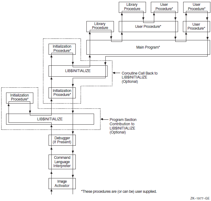
On Alpha and IA-64 systems, Figure 19.2, ''Sequence of Events During Image Initialization on Alpha and IA-64 systems'' shows the call instruction calling the debugger, if present, to set a breakpoint at the main program's entry point.
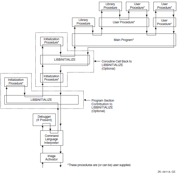
19.2. Initializing an Argument List
(start ,cli-coroutine [,image-info])
The start argument is the address of the entry in the
initialization vector that is used to perform the call.
The cli-coroutine argument is the address of a CLI coroutine to
obtain command arguments. For more information, see the VSI OpenVMS Utility Routines Manual.
The image-info argument is useful image information, such as
the program name.
. . . ADDL #4, 4(AP) ; Step to next initialization list entry MOVL @4(AP), R0 ; R0 = next address to call CALLG (AP), (R0) ; Call next initialization routine . . .
This coding sequence modifies the contents of an argument list entry. Thus, the sequence does not follow the OpenVMS calling standard. However, the argument list can be expanded in the future without requiring any change either to the debugger or to LIB$INITIALIZE.
19.3. Declaring Initialization Routines
Any library or user program module can declare an initialization routine. This routine is called when the image is started. The declaration is made by making a contribution to the LIB$INITIALIZE program section, which contains a list of routine entry point addresses to be called before the main program or main routine is called.
.EXTRN LIB$INITIALIZE ; Cause library initialization ; Dispatcher to be loaded .PSECT LIB$INITIALIZE, NOPIC, USR, CON, REL, GBL, NOSHR, NOEXE, RD, NOWRT, LONG .LONG INIT_PROC ; Contribute entry point address of ; initialization routine. .PSECT ...
The .EXTRN declaration links the initialization routine dispatcher, LIB$INITIALIZE, into your program's image. The reference contains a definition of the special global symbol LIB$INITIALIZE, which is the routine entry point address of the dispatcher. The linker stores the value of this special global symbol in the initialization list along with the starting address of the debugger and the main program. The GBL specification ensures that the PSECTLIB$INITIALIZE contribution is not affected by any clustering performed by the linker.
CLUSTER = <cluster name>,,,<module>, SYS$LIBRARY:STARLET.OLB/include = LIB$INITIALIZE COLLECT = <cluster name>, LIB$INITIALIZDZ, LIB$INITIALIZD_, LIB$INITIALIZE, LIB$INITIALIZE$
19.4. Dispatching to Initialization Routines
CALL init-proc (init-coroutine ,cli-coroutine [, image-info])
The init-coroutine argument is the address of a library
coroutine to be called to effect a coroutine linkage with
LIB$INITIALIZE.
The cli-coroutine is the address of a CLI coroutine used to
obtain command arguments.
The image-info argument is useful image information, such as
the program name.
19.5. Initialization Routine Options
Set up an exit handler by calling the Declare Exit Handler ($DCLEXH) system service, although exit handlers are generally set up by using a statically allocated first-time flag.
Initialize statically allocated storage, although this is done preferably at image activation time using compile-time and link-time data initialization declarations or by using a first-time call flag in its statically allocated storage.
Call the initialization dispatcher (instead of returning to it) by calling the
init-coroutineargument. This achieves a coroutine link. Control returns to the initialization routine when the main program returns control. Then the initialization routine should also return control to pass back the completion code returned by the main program (to the debugger or CLI, or both).Establish a condition handler in the current frame before performing the preceding actions. This leaves the initialization routine condition handler on the image stack for the duration of the image execution. This occurs after the CLI sets up the catchall stack frame handler and after the debugger sets up its stack frame handler. Thus, the initialization routine handler can override either of these handlers, because it will receive signals before they do.
19.6. Initialization Example
Establishes a handler
Calls the
init-coroutineargument routine, so that the coroutine calls the initialization dispatcherGains control after the main program returns
Returns to the normal exit processing
.ENTRY INIT_PROC, ^M<> ; No registers used
MOVAL HANDLER, (FP) ; Establish handler
... ; Perform any other initialization
CALLG (AP), @INIT_CO_ROUTINE(AP)
; Continue initialization which
10$: ; then calls main program or
; routine.
... ; Return here when main program
; returns with R0 = completion
RET ; Status return to normal exit
; processing with R0 = completion
; status
.ENTRY HANDLER, ^M<...> ; Register mask
... ; handle condition
; could unwind to 10$
MOVL #..., R0 ; Set completion status with a
; condition value
RET ; Resignal or continue depending
; on R0 being SS$_RESIGNAL or
; SS$_CONTINUE.Part III. Appendixes and Glossary
This part describes the generic macros used for calling system services, OpenVMS data types, and the distributed name services on OpenVMS VAX systems. It also includes a glossary of authentication terminology.
Appendix A. Generic Macros for Calling System Services
This appendix describes the use of generic macros to specify argument lists with appropriate symbols and conventions in the system services interface to MACRO assemblers.
The OpenVMS MACRO compiler compiles MACRO-32 source code written for OpenVMS VAX systems (the VAX MACRO assembler) into machine code that runs on OpenVMS Alpha and OpenVMS IA-64 systems. This Appendix also applies to MACRO-32 on OpenVMS Alpha and OpenVMS IA-64 systems.
System service macros generate argument lists and CALL instructions to call system services. These macros are located in the system library SYS$LIBRARY:STARLET.MLB. When you assemble a source program, this library is searched automatically for unresolved references.
Knowledge of VAX MACRO rules for assembly language programming is required for understanding the material presented in this appendix. The VAX MACRO and Instruction Set Reference Manual contains the necessary prerequisite information.
|
Macro |
Function |
|---|---|
|
$ |
Defines symbolic names for the argument list offsets |
|
$ |
Defines symbolic names for the argument list offsets and constructs the argument list |
|
$ |
Calls the system service and constructs the argument list |
|
$ |
Calls the system service and uses the argument list constructed by
$ |
A.1. Using Macros to Construct Argument Lists
- $
name - $
name_S
The macro you use depends on which macro you are going to use to call the system
service. If you use the $name_G macro to call a system service, you
should use the $name macro to construct the argument list. If you use
the $name_S macro to call a system service, you can also use it to
construct the argument list.
A.1.1. Specifying Arguments with the $name_S Macro and the
$name Macro
name_S or the $ name macro
to construct an argument list for a system service, you can specify arguments in any
one of three ways:By using keywords to describe the arguments. All keywords must be followed by an equals sign (=) and then by the value of the argument.
By using positional order, with omitted arguments indicated by commas in the argument positions. You can omit commas for optional trailing arguments.
By using both positional order and keyword names (positional arguments must be listed first).
$MYSERVICE arga ,[argb] ,[argc] ,argdFor purposes of this example, assume that arga and
argb require you to specify numeric values and that
argc and argd require you to
specify addresses.
name_S macro to call
$MYSERVICE.name_S MacroMYARGD: .LONG 100
.
.
.
$MYSERVICE_S ARGB=#0,ARGC=0,ARGA=#1,ARGD=MYARGDname_S MacroMYARGD: .LONG 100
.
.
.
$MYSERVICE_S #1,,,MYARGD PUSHAL MYARGD
PUSHL #0
PUSHL #0
PUSHL #1Note that all arguments, whether specified positionally or with keywords, must be valid assembler expressions because they are used as source operands in instructions.
name macro to construct an argument list for a later
call to $MYSERVICE.name MacroLIST: $MYSERVICE -
ARGB=0, -
ARGC=0, -
ARGA=1, -
ARGD=MYARGDname MacroLIST: $MYSERVICE -
1,,,MYARGDLIST: $MYSERVICE -
ARGB=0, -
ARGC=0, -
ARGA=1, -
ARGD=MYARGDNote that all arguments, whether specified positionally or by keyword, must be
expressions that the assembler can evaluate to generate .LONG or .ADDRESS data
directives. Contrast this to the arguments for the $name_S macro,
which must be valid assembler expressions because they are used as source operands
in instructions.
A.1.2. Conventions for Specifying Arguments to System Services
You must specify the arguments according to the VAX MACRO assembler rules for specifying and addressing operands.
Whether the system service requires an address or a value as the argument. In the VSI OpenVMS System Services Reference Manual, the descriptions of the arguments following a system service macro format always indicate whether the argument is an address. A Boolean value, number, or mask takes a value as the argument.
The system service macro being used. The expansions of the $
nameand $name_S macros in the examples in Section A.1.1, ''Specifying Arguments with the $name_S Macro and the $nameMacro '' show the code generated by each macro.
If you are unsure whether you specified a value or an address argument correctly, you can assemble the program with the .LIST MEB directive to check the macro expansion. See the VAX MACRO and Instruction Set Reference Manual for details.
A.1.3. Defining Symbolic Names for Argument List Offsets: $ name and
$ nameDEF
You can refer symbolically to arguments in the argument list. Each argument in an argument list has an offset from the beginning of the list; a symbolic name is defined for the numeric offset of each argument. If you use the symbolic names to refer to the arguments in a list, you do not have to remember the numeric offset (which is based on the position of the argument shown in the macro format).
Your program is easier to read.
If an argument list for a system service changes with a later release of a system, the symbols remain the same.
name is the name for the system service macro and
keyword is the keyword
argument:name$_keywordname$_NARGSname macro for a particular system service. You can
also define symbolic names for system service argument lists using the
$name DEF macro. This macro does not generate any executable
code; it merely defines the symbolic names so they can be used later in the program.
For example:$QIODEFThis macro defines the symbol QIO$_NARGS and the symbolic names for the $QIO argument list offsets.
You may need to use the $nameDEF macro either if you specify an
argument list to a system service without using the $name macro
or if a program refers to an argument list in a separately assembled module.
|
Symbolic Name |
Meaning |
|---|---|
|
READEF$_NARGS |
Number of arguments in the list (2) |
|
READEF$_EFN |
Offset of EFN argument (4) |
|
READEF$_STATE |
Offset of STATE argument (8) |
READLST: $READEF EFN=1,STATE=TEST1stateargument to call the service. The following lines
show how you can do this with a call to the $name_G
macro.MOVAL TEST2,READLST+READEF$_STATE $READEF_G READLST
The MOVAL instruction replaces the address TEST1 in the $READEF argument list with the address TEST2; the $READEF_G macro calls the system service with the modified list.
A.2. Using Macros to Call System Services
- $
name_S - $
name_G
The $
name_S macro requires you to supply the arguments to the system service in the system service macro. The macro generates code to push the argument list onto the call stack during program execution. With this macro, you can use registers to contain or point to arguments so that you can write reentrant programs.The $
name_G macro requires you to construct an argument list elsewhere int he program and specify the address of this list as an argument to the system service. (A macro is provided to create an argument list for each system service). With this macro, you can use the same argument list, with modifications if necessary, for more than one invocation of the macro.
The $name_S macro generates a CALLS instruction; the
$name_G macro generates a CALLG instruction. The services are
called according to the standard procedure-calling conventions. System services save all
registers except R0 and R1, and restore the saved registers before returning control to
the caller.
The following sections describe how to code system service calls using each of these macros.
A.2.1. The $name_S Macro
name_S macro call has the following
format:$name_S arg1, ..., argnIf the system service requires a value for an argument, either a PUSHL instruction or a MOVZWL to – (SP) instruction is generated.
If the system service requires an address for an argument, a PUSHAB, PUSHAW, PUSHAL, or PUSHAQ instruction is generated, depending on the context.
CALLS #n,@#SYS$name
In this format, n is the number of arguments on the
stack.
A.2.1.1. Example of $name_S Macro Call
name_S macro constructs the argument list at
execution time, you can supply addresses and values by using register addressing
modes. You can use the following line to execute the
$READEF_S
macro:$READEF_S EFN=#1,STATE=(R10)R10 contains the address of the longword that will receive the status of the flags.
PUSHAL (R10)
PUSHL #1
CALLS #2,@#SYS$READEFA.2.2. The $name_G Macro
name_G macro requires a single
operand:$name_G labelIn this format, label is the address of the argument list.
A.2.3. The $name Macro
name_G
macro. The $name_G macro (used with the $name
macro) is especially useful for doing the following:Making calls to system services that have long argument lists
Calling services repeatedly during the execution of a single program with the same, or essentially the same, argument list
label: $name arg1,...,argn
label Symbolic address of the generated argument list. This is the label given as an
argument in the $name_G macro.
$name The service macro name.
arg1,...,argn Arguments to be placed in successive longwords in the argument list.
A.2.4. Example of $name and $name_G Macro
Calls
The example that follows shows how you can write a call to the Read Event Flags
($READEF) system service using an argument list created
by $name.
$READEF efn ,stateThe efn argument must specify the number of an event flag
cluster, and the state argument must supply the address of a
longword that will receive the contents of the cluster.
name macro, as
follows:READLST:
$READEF EFN=1, - ; Argument list for $READEF
STATE=TESTFLAGREADLST:
.LONG 2 ; Argument list for $READEF
.ADDRESS 1
.ADDRESS -
TESTFLAG$READEF_G READLSTCALLG READLST,@#SYS$READEFSYS$READEF is the name of a vector to the entry point of the Read Event Flags system service. The linker automatically resolves the entry point addresses for all system services.
Appendix B. OpenVMS Data Types
As part of the OpenVMS common language environment, the OpenVMS system routine data types provide compatibility between procedure calls that support many different high-level languages. Specifically, the OpenVMS data types apply to the Alpha, I64, and VAX architectures as the mechanism for passing argument data between procedures. This appendix describes the context and structure of the OpenVMS system routine data types and identifies the associated declarations to each of the specific high-level language implementations.
B.1. OpenVMS Data Types
Note
The OpenVMS usage entry is not a traditional data type such as the OpenVMS standard data types—byte, word, longword, and so on. It is significant only within the OpenVMS operating system environment and is intended solely to expedite data declarations within application programs.
Find the data type in Table B.1, ''OpenVMS Usage Data Type Entries'' and read its definition.
Find the same OpenVMS data type in the appropriate high-level language implementation table (Table B.2 through Table B.13) and its corresponding source-language type declaration.
Use this code as your type declaration in your application program. Note that, in some instances, you might have to modify the declaration.
|
Data Type |
Definition | ||
|---|---|---|---|
|
access_bit_names |
Homogeneous array of 32 quadword descriptors; each descriptor defines the name of one of the 32 bits in an access mask. The first descriptor names bit <0>, the second descriptor names bit <1>, and so on. | ||
|
access_mode |
Unsigned byte denoting a hardware access mode. This unsigned byte can contain one of four values: 0, kernel mode; 1, executive mode; 2, supervisor mode; and 3, user mode. | ||
|
address |
Unsigned value denoting a position in virtual memory. On VAX systems the value is an unsigned longword. On Alpha and IA-64 systems the value is an unsigned quadword that can either be a 32-bit, sign-extended value (the high-order 33 bits are the same) to represent 32-bit addresses or a 64-bit value to represent 64-bit addresses. | ||
|
address_range |
Unsigned quadword denoting a range of virtual addresses that identifies an area of memory. The first longword specifies the beginning address in the range; the second longword specifies the ending address in the range. | ||
|
arg_list |
Vector in memory representing a procedure call argument list containing a sequence of entries together with a count of the number of argument entries. On VAX systems, and Alpha and IA-64 systems when passing 32-bit
arguments, an argument list (shown in the following figure) is
represented as a vector of longwords, where the first longword
contains the count and each remaining longword contains one
argument. On Alpha and IA-64 systems when passing 64-bit
arguments, an argument list is represented as a vector of
quadwords, where the first quadword contains the count and each
remaining quadword contains one argument.
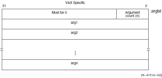 | ||
|
ast_procedure |
The procedure value of a procedure to be called at asynchronous system trap (AST) level. (Procedures that are not to be called at AST level are of type procedure). | ||
|
boolean |
Unsigned longword denoting a Boolean truth value flag. This longword can have one of two values: 1 (true) or 0 (false). | ||
|
buffer |
Generic term for temporary memory. | ||
|
buffer_length |
Generic term for temporary memory that indicates the size of a buffer. | ||
|
byte_signed |
Same as the data type byte integer (signed) in Table 1.3, ''Standard Data Types and Their Descriptor Field Symbols''. | ||
|
byte_unsigned |
Same as the data type byte (unsigned) in Table 1.3, ''Standard Data Types and Their Descriptor Field Symbols''. | ||
|
channel |
Unsigned word integer that is an index to an I/O channel. | ||
|
char_string |
String of from 0 to 65535 eight-bit characters. This OpenVMS
data type is the same as the data type character string in Table 1.3, ''Standard Data Types and Their Descriptor Field Symbols''. The following diagram shows
the character string XYZ:
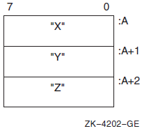 | ||
|
complex_number |
One of the OpenVMS standard complex floating-point data types. The six complex floating point numbers are F_floating complex, D_floating complex, G_floating complex, S_floating, T_floating, and X_floating. As shown in the following figure, an F_floating point complex
number (real, imaginary) is composed of two F_floating
point numbers: the first is the real part of the complex number;
the second is the imaginary part. For more structure detail, see
floating_point described later in this table.
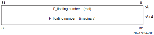 | ||
|
As shown in the following figure, a D_floating point complex number (real, imaginary) is composed of two D_floating point numbers: the first is the real part of the complex number; the second is the imaginary part. For more structure detail, see
floating_point described later in this table.
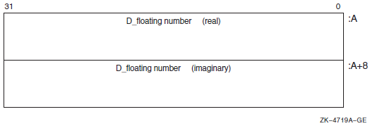 | |||
|
As shown in the following figure, a G_floating point complex number (real, imaginary) is composed of two G_floating point numbers:the first is the real part of the complex number; the second is the imaginary part. For more structure detail, see
floating_point described later in this table.
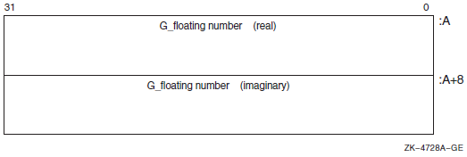 | |||
|
On VAX systems only, as shown in the following figure, an H_floating complex number (real, imaginary) is composed of two H_floating point numbers: the first is the real part of the complex number; the second is the imaginary part. Note that H_float numbers apply to VAX environments only. For more structure detail, see
floating_point described later in this table.
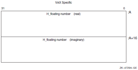 | |||
|
On Alpha and IA-64 systems only, as shown in the following figure, an S_floating point complex number (real, imaginary) is composed of two S_floating point numbers: the first is the real part of the complex number; the second is the imaginary part. For more structure detail, see
floating_point described later in this table.
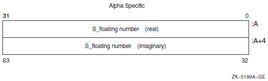 | |||
|
On Alpha and IA-64 systems only, as shown in the following figure, a T_floating complex number (real, imaginary) is composed of two T_floating point numbers: the first is the real part of the complex number; the second is the imaginary part. For more structure detail, see
floating_point described later in this table.
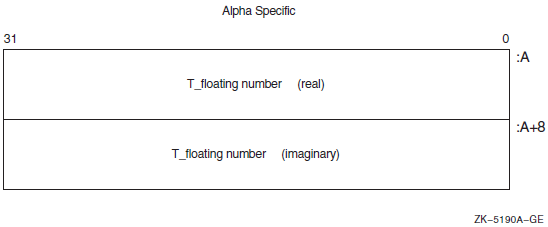 | |||
|
On Alpha and IA-64 systems only, as shown in the following figure, an X_floating complex number (real, imaginary) is composed of two X_floating point numbers: the first is the real part of the complex number; the second is the imaginary part. For more structure detail, see
floating_point described later in this table.
| |||
|
cond_value |
Longword integer for VAX or quadword sign-extended integer for
Alpha and I64 denoting a condition value (a return status or
system condition code) that is typically returned by a procedure
in R0 on VAX and Alpha and R8 on IA-64. Each numeric condition
value has a unique symbolic name in the following format, where
the severity condition code is a mnemonic describing the return condition:
| ||
|
Depending on your specific needs, you can test just the
low-order bit, the low-order three bits, or the entire value.
| |||
|
context |
Unsigned longword used by a called procedure to maintain position over an iterative sequence of calls. The data type is usually initialized by the caller but thereafter is manipulated by the called procedure. | ||
|
date_time |
Unsigned 64-bit binary integer denoting a date and time as the number of elapsed 100-nanosecond units since 00:00 o'clock, November 17, 1858. This OpenVMS data type is the same as the data type absolute date and time in Table 1.3, ''Standard Data Types and Their Descriptor Field Symbols''. | ||
|
device_name |
Character string denoting the 1- to 15-character name of a device. This string can be a logical name, but if it is, it must translate to a valid device name. If the device name contains a colon (:), the colon and the characters following it are ignored. An underscore (_) preceding the device name string indicates that the string is a physical device name. | ||
|
ef_cluster_name |
Character string denoting the 1- to 15-character name of an event flag cluster. This string can be a logical name, but if it is, it must translate to a valid event-flag cluster name. | ||
|
ef_number |
Unsigned longword integer denoting the number of an event flag. Local event flags numbered 32 to 63 are available to your programs. | ||
|
exit_handler_block |
Variable-length structure denoting an exit-handler control
block. This control block, which describes the exit handler, is
depicted in the following diagram:
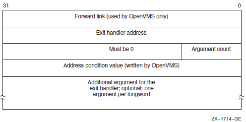 | ||
|
fab |
Structure denoting an RMS file access block. | ||
|
file_protection |
Unsigned word that is a 16-bit mask that specifies file protection. The mask contains four 4-bit fields, each of which specifies the protection (access protected when a bit is 1) to be applied to file access attempts by one of the four categories of users, from rightmost field to leftmost field: (1) system users, (2) file owner, (3) users in the same UIC group as the owner, and (4) all other users (the world). Each field specifies, from rightmost bit to leftmost bit: (1) read access, (2) write access, (3) execute access, (4) delete access. Set bits indicate that access is denied. The following diagram depicts the 16-bit file-protection mask:
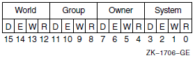 | ||
|
floating_point |
One of the Alpha, I64, or VAX standard floating-point data types. VAX systems support F_floating, D_floating, G_floating, or H_floating data types. In addition, Alpha systems support S_floating, T_floating, or X_floating types. IPF systems support S_floating and T_floating in hardware but the compilers can generate code to support F_floating, D_floating, and G_floating data types. The following paragraphs briefly describe these data types: The structure of an F_floating datum follows. It contains two
fraction fields. Note that the field 2 extension holds the least
significant portion of the fractional number.
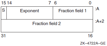 | ||
|
The structure of a D_floating datum follows. It contains four fraction fields. Note that the field 4 extension holds the least significant portion of the fractional number. While OpenVMS Alpha and I64 support the manipulation of
D_floating and D_floating complex data, compiled-code support
invokes conversion from D_floating to G_floating for Alpha and
I64 arithmetic operations. Also, the conversion of G_floating
intermediate results are converted back to D_floating when
needed either for stores to memory or for passing parameters.
However, use of D_floating data in arithmetic operations on
Alpha and I64 produces results that are limited to G_float precision.
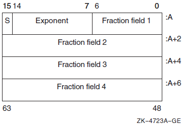 | |||
|
The structure of a G_floating datum follows. It contains four
fraction fields. Note that the field 4 extension holds the least
significant portion of the fractional number.
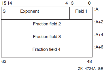 | |||
|
The structure of an H_floating datum follows (VAX systems
only). It contains seven fraction fields. Note that the field 7
extension holds the least significant portion of the fractional number.
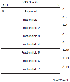 | |||
|
The structure of an S_floating datum follows (Alpha and IA-64 systems only). It contains two fraction fields. Note that the
field 2 extension holds the least significant portion of the
fractional number.
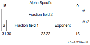 | |||
|
The structure of a T_floating datum follows (Alpha and IA-64 systems only). It contains four fraction fields. Note that
fraction field 1 holds the most significant bits, and the field
4 extension holds the least significant portion of the
fractional number.
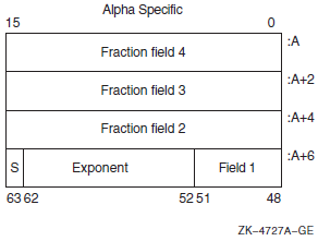 | |||
|
The structure of an X_floating datum follows (Alpha and IA-64 systems only). An X_floating datum occupies 16 contiguous bytes
in memory or two consecutive floating-point registers. It
contains seven fraction fields (0–6). Note that fraction
field 6 holds the most significant bits and the field 0
extension holds the least significant portion of the fractional number.
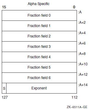 | |||
|
function_code |
Unsigned longword specifying the exact operations a procedure is to perform. This longword has two word-length fields:the first field is a number specifying the major operation; the second field is a mask or bit vector specifying various suboperations within the major operation. | ||
|
identifier |
Unsigned longword that identifies an object returned by the system. | ||
|
invo_context_blk? |
Structure that contains the context information of a specific procedure invocation in a call chain. For information describing the invocation context block, see the VSI OpenVMS Calling Standard. | ||
|
invo_handle? |
Unsigned longword that refers to a specific procedure invocation at run time. The invo_handle longword defines the invocation handle of a procedure in a call chain. | ||
|
io_status_block |
Quadword structure containing information returned by a procedure that completes asynchronously. The information returned varies depending on the procedure. | ||
|
The following figure illustrates the format of the information
written in the IOSB for SYS$QIO:
| |||
|
The first word contains a condition value indicating the success or failure of the operation. The condition values used are the same as for all returns from system services; for example, SS$_NORMAL indicates successful completion. The second word contains the number of bytes actually transferred in the I/O operation. Note that for some devices this word contains only the low-order word of the count. The second longword contains device-dependent return information. To ensure successful I/O completion and the integrity of data transfers, you should check the IOSB following I/O requests, particularly for device-dependent I/O functions. | |||
|
item_list_2 |
Structure that consists of one or more item descriptors and is terminated by a longword containing 0. Each item descriptor is a 2-longword structure that contains three fields. The following diagram depicts a single-item descriptor:
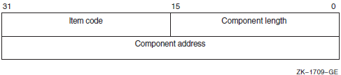 | ||
|
The first field is a word in which the service writes the length (in characters) of the requested component. If the service does not locate the component, it returns the value 0 in this field and in the component address field. The second field contains a user-supplied, word-length symbolic code that specifies the component desired. The item codes are defined by the macros specific to the service. The third field is a longword in which the service writes the starting address of the component. This address is within the input string itself. | |||
|
item_list_3 |
Structure that consists of one or more item descriptors and is terminated by a longword containing 0. Each item descriptor is a 3-longword structure that contains four fields. | ||
|
The following diagram depicts the format of a single-item descriptor:
| |||
|
The first field is a word containing a user-supplied integer specifying the length (in bytes) of the buffer in which the service writes the information. The length of the buffer needed depends on the item code specified in the item code field of the item descriptor. If the value of buffer length is too small, the service truncates the data. The second field is a word containing a user-supplied symbolic code specifying the item of information that the service is to return. These codes are defined by macros specific to the service. The third field is a longword containing the user-supplied address of the buffer in which the service writes the information. The fourth field is a longword containing the user-supplied address of a word in which the service writes the length in bytes of the information it actually returned. | |||
|
item_list_pair |
Structure that consists of one or more longword pairs, or doublets, and is terminated by a longword containing 0. Typically, the first longword contains an integer value such as a code. The second longword can contain a real or integer value. | ||
|
item_quota_list |
Structure that consists of one or more quota descriptors and is terminated by a byte containing a value defined by the symbolic name PQL$_LISTEND. Each quota descriptor consists of a 1-byte quota name followed by an unsigned longword containing the value for that quota. | ||
|
lock_id |
Unsigned longword integer denoting a lock identifier. This lock identifier is assigned to a lock by the lock manager when the lock is granted. | ||
|
lock_status_block |
Structure into which the lock manager writes status information about a lock. A lock status block always contains at least two longwords: the first word of the first longword contains a condition value; the second word of the first longword is reserved for OpenVMS. The second longword contains the lock identifier. The lock status block receives the final condition value plus the lock identification, and optionally contains a lock value block. When a request is queued, the lock identification is stored in the lock status block even if the lock has not been granted. This allows a procedure to dequeue locks that have not been granted. The condition value is placed in the lock status block only when the lock is granted (or when errors occur in granting the lock). | ||
|
The following diagram depicts a lock status block that
includes the optional 16-byte (VAX or Alpha) or 64-byte (Alpha
or I64) lock value block:
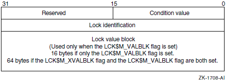 | |||
|
lock_value_block |
A 16-byte block (VAX and Alpha) or a 64-byte block(Alpha and I64) that the lock manager includes in a lock status block if the user requests it. The contents of the lock value block are user-defined and are not interpreted by the lock manager. | ||
|
logical_name |
Character string of from 1 to 255 characters that identifies a logical name or equivalence name to be manipulated by OpenVMS logical name system services. Logical names that denote specific OpenVMS objects have their own OpenVMS types; for example, a logical name identifying a device has the OpenVMS type device_name. | ||
|
longword_signed |
Same as the data type longword integer (signed) in Table 1.3, ''Standard Data Types and Their Descriptor Field Symbols''. | ||
|
longword_unsigned |
Same as the data type longword (unsigned) in Table 1.3, ''Standard Data Types and Their Descriptor Field Symbols''. | ||
|
mask_byte |
Unsigned byte in which each bit is interpreted by the called procedure. A mask is also referred to as a set of flags or as a bit mask. | ||
|
mask_longword |
Unsigned longword in which each bit is interpreted by the called procedure. A mask is also referred to as a set of flags or as a bit mask. | ||
|
mask_quadword |
Unsigned quadword in which each bit is interpreted by the called procedure. A mask is also referred to as a set of flags or as a bit mask. | ||
|
mask_word |
Unsigned word in which each bit is interpreted by the called procedure. A mask is also referred to as a set of flags or as a bit mask. | ||
|
mechanism_args |
Structure (array) of mechanism argument vectors that contain information about the machine state when an exception occurs or when a condition is signaled. For more information concerning mechanism argument vectors, see the VSI OpenVMS Calling Standard. | ||
|
null_arg |
Unsigned longword denoting a null argument. (A null argument is one whose only purpose is to hold a place in the argument list.) | ||
|
octaword_signed |
Same as the data type octaword integer (signed) in Table 1.3, ''Standard Data Types and Their Descriptor Field Symbols''. | ||
|
octaword_unsigned |
Same as the data type octaword (unsigned) in Table 1.3, ''Standard Data Types and Their Descriptor Field Symbols''. | ||
|
page_protection |
Unsigned longword specifying page protection to be applied by the Alpha and I64 or VAX hardware. Protection values are specified using bits <3:0>; bits <31:4> are ignored. If you specify the protection as 0, the protection defaults to kernel read only. The $PRTDEF macro defines the following symbolic names for the protection codes: | ||
|
Symbol |
Description | ||
|
PRT$C_NA |
No access | ||
|
PRT$C_KR |
Kernel read only | ||
|
PRT$C_KW |
Kernel write | ||
|
PRT$C_ER |
Executive read only | ||
|
PRT$C_EW |
Executive write | ||
|
PRT$C_SR |
Supervisor read only | ||
|
PRT$C_SW |
Supervisor write | ||
|
PRT$C_UR |
User read only | ||
|
PRT$C_UW |
User write | ||
|
PRT$C_ERKW |
Executive read; kernel write | ||
|
PRT$C_SRKW |
Supervisor read; kernel write | ||
|
PRT$C_SREW |
Supervisor read; executive write | ||
|
PRT$C_URKW |
User read; kernel write | ||
|
PRT$C_UREW |
User read; executive write | ||
|
PRT$C_URSW |
User read; supervisor write | ||
|
procedure |
Procedure value of a procedure that is not to be called at AST level. (Arguments specifying procedures to be called at AST level have the OpenVMS type ast_procedure). A procedure value is an address that represents a procedure. On VAX systems, a procedure value is the address of the procedure entry mask. On Alpha and IA-64 systems, a procedure value is the address of the procedure descriptor for the procedure. For more information, see the VSI OpenVMS Calling Standard. | ||
|
process_id |
Unsigned longword integer denoting a process identification (PID). This process identification is assigned to a process by the operating system when the process is created. | ||
|
process_name |
Character string containing 1 to 15 characters that specifies the name of a process. | ||
|
quadword_signed |
Same as the data type quadword integer (signed) in Table 1.3, ''Standard Data Types and Their Descriptor Field Symbols''. | ||
|
quadword_unsigned |
Same as the data type quadword (unsigned) in Table 1.3, ''Standard Data Types and Their Descriptor Field Symbols''. | ||
|
rights_holder |
Unsigned quadword specifying a user's access rights to a
system object. This quadword consists of two fields: the first
is an unsigned longword identifier (OpenVMS type rights_id), and the second is a
longword bit mask in which each bit specifies an access right.
The following diagram depicts the format of a rights holder:
| ||
|
rights_id |
Unsigned longword denoting a rights identifier, which identifies an interest group in the context of the OpenVMS security environment. This rights environment might consist of all or part of a user's identification code (UIC). Identifiers have two formats in the rights database: UIC
format (OpenVMS type uic) and
ID format. The high-order bits of the identifier value specify
the format of the identifier. Two high-order zero bits identify
a UIC format identifier; bit <31>, set to
1, identifies an ID format identifier.
Bits <30:28> are reserved for OpenVMS. The remaining bits
specify the identifier value. The following diagram depicts the
ID format of a rights identifier:
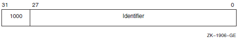 | ||
|
To the system, an identifier is a binary value; however, to make identifiers easy to use, the system translates the binary identifier value into an identifier name. The binary value and the identifier name are associated in the rights database. | |||
|
An identifier name consists of 1 to 31 alphanumeric characters and contains at least one nonnumeric character. An identifier name cannot consist entirely of numeric characters. It can include the characters A through Z, dollar signs ($), and underscores (_), as well as the numbers 0 through 9. Any lowercase characters are automatically converted to uppercase. | |||
|
rab |
Structure denoting an RMS record access block. | ||
|
section_id |
Unsigned quadword denoting a global section identifier. This identifier specifies the version of a global section and the criteria to be used in matching that global section. | ||
|
section_name |
Character string denoting a 1- to 43-character global-section name. This character string can be a logical name, but it must translate to a valid global section name. | ||
|
system_access_id |
Unsigned quadword that denotes a system identification value to be associated with a rights database. | ||
|
time_name |
Character string specifying a time value in an OpenVMS format. | ||
|
transaction_id |
Unsigned octaword that denotes a unique transaction identifier. | ||
|
uic |
Unsigned longword denoting a user identification code(UIC).
Each UIC is unique and represents a system user. The UIC
identifier contains two high-order bits that designate format, a
member field, and a group field. Member numbers range from 0 to
65534; group numbers range from 1 to 16382. The following
diagram depicts the UIC format:
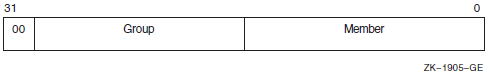 | ||
|
user_arg |
On VAX systems, an unsigned longword, and on Alpha and IA-64 systems, an unsigned quadword denoting a user-defined argument. The longword (VAX) or quadword (Alpha and I64) is passed to a procedure as an argument, but the contents of the longword or quadword are defined and interpreted by the user. | ||
|
varying_arg |
On VAX systems, an unsigned longword, and on Alpha and IA-64 systems, an unsigned quadword denoting a varying argument. A variable argument can have variable types, depending on specifications made for other arguments in the call. | ||
|
vector_byte_signed |
Homogeneous array whose elements are all signed bytes. | ||
|
vector_byte_unsigned |
Homogeneous array whose elements are all unsigned bytes. | ||
|
vector_longword_signed |
Homogeneous array whose elements are all signed longwords. | ||
|
vector_longword_unsigned |
Homogeneous array whose elements are all unsigned longwords. | ||
|
vector_quadword_signed |
Homogeneous array whose elements are all signed quadwords. | ||
|
vector_quadword_unsigned |
Homogeneous array whose elements are all unsigned quadwords. | ||
|
vector_word_signed |
Homogeneous array whose elements are all signed words. | ||
|
vector_word_unsigned |
Homogeneous array whose elements are all unsigned words. | ||
|
word_signed |
Same as the data type word integer (signed) in Table 1.3, ''Standard Data Types and Their Descriptor Field Symbols''. | ||
|
word_unsigned |
Same as the data type word (unsigned) in Table 1.3, ''Standard Data Types and Their Descriptor Field Symbols''. | ||
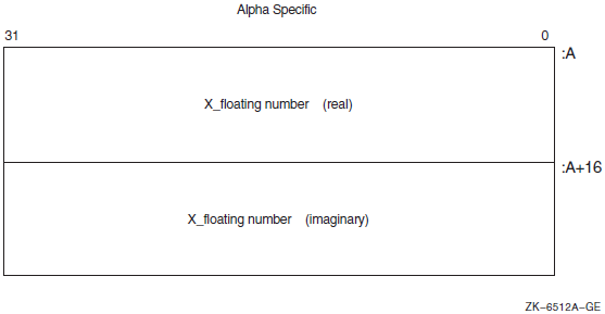
B.2. Ada Implementations
|
OpenVMS Data Types |
Ada Declarations |
|---|---|
|
access_bit_names |
STARLET.ACCESS_BIT_NAMES_TYPE |
|
access_mode |
STARLET.ACCESS_MODE_TYPE |
|
address |
SYSTEM.ADDRESS |
|
address_range |
STARLET.ADDRESS_RANGE_TYPE |
|
arg_list |
STARLET.ARG_LIST_TYPE |
|
ast_procedure |
SYSTEM.AST_HANDLER |
|
boolean |
STANDARD.BOOLEAN |
|
byte_signed |
STANDARD.SHORT_SHORT_INTEGER |
|
byte_unsigned |
SYSTEM.UNSIGNED_BYTE |
|
channel |
STARLET.CHANNEL_TYPE |
|
char_string |
STANDARD.STRING |
|
complex_number |
User-defined record |
|
cond_value |
CONDITION_HANDLING.COND_VALUE_TYPE |
|
context |
STARLET.CONTEXT_TYPE |
|
date_time |
STARLET.DATE_TIME_TYPE |
|
device_name |
STARLET.DEVICE_NAME_TYPE |
|
ef_cluster_name |
STARLET.EF_CLUSTER_NAME_TYPE |
|
ef_number |
STARLET.EF_NUMBER_TYPE |
|
exit_handler_block |
STARLET.EXIT_HANDLER_BLOCK_TYPE |
|
fab |
STARLET.FAB_TYPE |
|
file_protection |
STARLET.FILE_PROTECTION_TYPE |
|
floating_point | |
|
function_code |
STARLET.FUNCTION_CODE_TYPE |
|
identifier |
SYSTEM.UNSIGNED_LONGWORD |
|
invo_context_blk? |
User-defined record |
|
invo_handle? |
SYSTEM.UNSIGNED_LONGWORD |
|
io_status_block |
STARLET.IOSB_TYPE |
|
item_list_pair |
SYSTEM.UNSIGNED_LONGWORD |
|
item_list_2 |
STARLET.ITEM_LIST_2_TYPE |
|
item_list_3 |
STARLET.ITEM_LIST_3_TYPE |
|
item_quota_list |
User-defined record |
|
lock_id |
STARLET.LOCK_ID_TYPE |
|
lock_status_block |
STARLET.LOCK_STATUS_BLOCK_TYPE |
|
lock_value_block |
STARLET.LOCK_VALUE_BLOCK_TYPE |
|
logical_name |
STARLET.LOGICAL_NAME_TYPE |
|
longword_signed |
STANDARD.INTEGER |
|
longword_unsigned |
SYSTEM.UNSIGNED_LONGWORD |
|
mask_byte |
SYSTEM.UNSIGNED_BYTE |
|
mask_longword |
SYSTEM.UNSIGNED_LONGWORD |
|
mask_quadword |
SYSTEM.UNSIGNED_QUADWORD |
|
mask_word |
SYSTEM.UNSIGNED_WORD |
|
mechanism_args |
STARLET.CHFDEF2_TYPE |
|
null_arg |
SYSTEM.UNSIGNED_LONGWORD |
|
octaword_signed |
array (1..4) of SYSTEM.UNSIGNED_LONGWORD |
|
octaword_unsigned |
array (1..4) of SYSTEM.UNSIGNED_LONGWORD |
|
page_protection |
STARLET.PAGE_PROTECTION_TYPE |
|
procedure |
SYSTEM.ADDRESS |
|
process_id |
STARLET.PROCESS_ID_TYPE |
|
process_name |
STARLET.PROCESS_NAME_TYPE |
|
quadword_signed |
SYSTEM.UNSIGNED_QUADWORD |
|
quadword_unsigned |
SYSTEM.UNSIGNED_QUADWORD |
|
rights_holder |
STARLET.RIGHTS_HOLDER_TYPE |
|
rights_id |
STARLET.RIGHTS_ID_TYPE |
|
rab |
STARLET.RAB_TYPE |
|
section_id |
STARLET.SECTION_ID_TYPE |
|
section_name |
STARLET.SECTION_NAME_TYPE |
|
system_access_id |
STARLET.SYSTEM_ACCESS_ID_TYPE |
|
time_name |
STARLET.TIME_NAME_TYPE |
|
transaction_id |
array (1..4) of SYSTEM.UNSIGNED_LONGWORD |
|
uic |
STARLET.UIC_TYPE |
|
user_arg |
STARLET.USER_ARG_TYPE |
|
varying_arg |
SYSTEM.UNSIGNED_LONGWORD |
|
vector_byte_signed |
array (1..n) of STANDARD.SHORT_SHORT_INTEGER |
|
vector_byte_unsigned |
array (1..n) of SYSTEM.UNSIGNED_BYTE |
|
vector_longword_signed |
array (1..n) of STANDARD.INTEGER |
|
vector_longword_unsigned |
array (1..n) of SYSTEM.UNSIGNED_LONGWORD |
|
vector_quadword_signed |
array (1..n) ofSYSTEM.UNSIGNED_QUADWORD |
|
vector_quadword_unsigned |
array (1..n) of SYSTEM.UNSIGNED_QUADWORD |
|
vector_word_signed |
array (1..n) of STANDARD.SHORT_INTEGER |
|
vector_word_unsigned |
array(1..n) of SYSTEM.UNSIGNED_WORD |
|
word_signed |
STANDARD.SHORT_INTEGER |
|
word_unsigned |
SYSTEM.UNSIGNED_WORD |
B.3. Application Programming Language (APL) Implementations
|
OpenVMS Data Types |
APL Declarations |
|---|---|
|
access_bit_names |
na |
|
access_mode |
/TYPE=BU |
|
address |
na |
|
address_range |
na |
|
arg_list |
na |
|
ast_procedure |
na |
|
boolean |
/TYPE=V |
|
byte_signed |
/TYPE=B |
|
byte_unsigned |
/TYPE=BU |
|
channel |
/TYPE=WU |
|
char_string |
/TYPE=T |
|
complex_number |
|
|
cond_value |
/TYPE=LU |
|
context |
na |
|
date_time |
na |
|
device_name |
/TYPE=T |
|
ef_cluster_name |
/TYPE=T |
|
ef_number |
/TYPE=LU |
|
exit_handler_block |
na |
|
fab |
na |
|
file_protection |
/TYPE=WU |
|
floating_point |
|
|
function_code |
na |
|
identifier |
na |
|
io_status_block |
na |
|
item_list_2 |
na |
|
item_list_3 |
na |
|
item_list_pair |
na |
|
item_quota_list |
na |
|
lock_id |
/TYPE=LU |
|
lock_status_block |
na |
|
lock_value_block |
na |
|
logical_name |
/TYPE=T |
|
longword_signed |
/TYPE=L |
|
longword_unsigned |
/TYPE=LU |
|
mask_byte |
/TYPE=BU |
|
mask_longword |
/TYPE=LU |
|
mask_quadword |
na |
|
mask_word |
/TYPE=WU |
|
null_arg |
/TYPE=LU |
|
octaword_signed |
na |
|
octaword_unsigned |
na |
|
page_protection |
/TYPE=LU |
|
procedure |
na |
|
process_id |
/TYPE=LU |
|
process_name |
/TYPE=T |
|
quadword_signed |
na |
|
quadword_unsigned |
na |
|
rights_holder |
na |
|
rights_id |
/TYPE=LU |
|
rab |
na |
|
section_id |
na |
|
section_name |
/TYPE=T |
|
system_access_id |
na |
|
time_name |
/TYPE=T |
|
transaction_id |
na |
|
uic |
/TYPE=LU |
|
user_arg |
/TYPE=LU |
|
varying_arg |
na |
|
vector_byte_signed |
/TYPE=B |
|
vector_byte_unsigned |
/TYPE=BU |
|
vector_longword_signed |
/TYPE=L |
|
vector_longword_unsigned |
/TYPE=LU |
|
vector_quadword_signed |
na |
|
vector_quadword_unsigned |
na |
|
vector_word_signed |
/TYPE=W |
|
vector_word_unsigned |
/TYPE=WU |
|
word_signed |
/TYPE=W |
|
word_unsigned |
/TYPE=WU |
B.4. BASIC Implementations
|
OpenVMS Data Type |
BASIC Declarations |
|---|---|
|
access_bit_names |
na |
|
access_mode |
BYTE (signed) |
|
address |
LONG |
|
address_range |
LONG address_range (1) |
|
arg_list |
na |
|
ast_procedure |
EXTERNAL LONG ast_proc |
|
boolean |
LONG |
|
byte_signed |
BYTE |
|
byte_unsigned |
BYTE? |
|
channel |
WORD |
|
char_string |
STRING |
|
complex_number |
RECORD complex |
|
cond_value |
LONG |
|
context |
LONG |
|
date_time |
RECORD date_time |
|
device_name |
STRING |
|
ef_cluster_name |
STRING |
|
ef_number |
LONG |
|
exit_handler_block |
RECORD EHCB |
|
fab |
na |
|
file_protection |
LONG |
|
floating_point |
|
|
function_code |
RECORD function-code |
|
identifier |
LONG |
|
io_status_block |
RECORD iosb |
|
item_list_2 |
RECORD item_list_two |
|
item_list_3 |
RECORD item_list_3 |
|
item_list_pair |
RECORD item_list_pair |
|
item_quota_list |
RECORD item_quota_list |
|
lock_id |
LONG |
|
lock_status_block |
na |
|
lock_value_block |
na |
|
logical_name |
STRING |
|
longword_signed |
LONG |
|
longword_unsigned |
LONG? |
|
mask_byte |
BYTE |
|
mask_longword |
LONG |
|
mask_quadword |
RECORD quadword |
|
mask_word |
WORD |
|
null_arg |
A null argument is indicated by a comma used as a placeholder in the argument list. |
|
octaword_signed |
na |
|
octaword_unsigned |
na |
|
page_protection |
LONG |
|
procedure |
EXTERNAL LONG proc |
|
process_id |
LONG |
|
process_name |
STRING |
|
quadword_signed |
RECORD quadword |
|
quadword_unsigned |
RECORD quadword |
|
rights_holder |
RECORD quadword |
|
rights_id |
LONG |
|
rab |
na |
|
section_id |
RECORD quadword |
|
section_name |
STRING |
|
system_access_id |
RECORD quadword |
|
time_name |
STRING |
|
transaction_id |
na |
|
uic |
LONG |
|
user_arg |
LONG |
|
varying_arg |
Depends on the application. |
|
vector_byte_signed |
BYTE array n |
|
vector_byte_unsigned |
BYTE array n? |
|
vector_longword_signed |
LONG array n |
|
vector_longword_unsigned |
LONG array n? |
|
vector_quadword_signed |
na |
|
vector_quadword_unsigned |
na |
|
vector_word_signed |
WORD array n |
|
vector_word_unsigned |
WORD array n? |
|
word_signed |
WORD |
|
word_unsigned |
WORD? |
B.5. BLISS Implementations
|
OpenVMS Data Types |
BLISS Declarations |
|---|---|
|
access_bit_names |
BLOCKVECTOR[32,8,BYTE] |
|
access_mode |
UNSIGNED BYTE |
|
address |
UNSIGNED LONG |
|
address_range |
VECTOR[2,LONG,UNSIGNED] |
|
arg_list |
|
|
ast_procedure |
UNSIGNED LONG |
|
boolean |
UNSIGNED LONG |
|
byte_signed |
SIGNED BYTE |
|
byte_unsigned |
UNSIGNED BYTE |
|
channel |
UNSIGNED WORD |
|
char_string |
VECTOR[65536,BYTE,UNSIGNED] |
|
complex_number |
|
|
cond_value |
UNSIGNED LONG |
|
context |
UNSIGNED LONG |
|
date_time |
VECTOR[2,LONG,UNSIGNED] |
|
device_name |
|
|
ef_cluster_name |
|
|
ef_number |
UNSIGNED LONG |
|
exit_handler_block |
|
|
fab |
$FAB_DECL (from STARLET.REQ) |
|
file_protection |
BLOCK[2,BYTE] |
|
floating_point |
|
|
function_code |
BLOCK[2,WORD] |
|
identifier |
UNSIGNED LONG |
|
io_status_block |
BLOCK[8,BYTE] |
|
item_list_2 |
|
|
item_list_3 |
|
| |
|
item_list_pair |
|
|
item_quota_list |
|
|
lock_id |
UNSIGNED_LONG |
|
lock_status_block |
|
|
lock_value_block |
BLOCK[16,BYTE] |
|
logical_name |
VECTOR[255,BYTE,UNSIGNED] |
|
longword_signed |
SIGNED LONG |
|
longword_unsigned |
UNSIGNED LONG |
|
mask_byte |
BITVECTOR[8] |
|
mask_longword |
BITVECTOR[32] |
|
mask_quadword |
BITVECTOR[64] |
|
mask_word |
BITVECTOR[16] |
|
null_arg |
UNSIGNED LONG |
|
octaword_signed |
VECTOR[4,LONG,UNSIGNED] |
|
octaword_unsigned |
VECTOR[4,LONG,UNSIGNED] |
|
page_protection |
UNSIGNED LONG |
|
procedure |
UNSIGNED LONG |
|
process_id |
UNSIGNED LONG |
|
process_name |
|
|
quadword_signed |
VECTOR[2,LONG,UNSIGNED] |
|
quadword_unsigned |
VECTOR[2,LONG,UNSIGNED] |
|
rights_holder |
BLOCK[8,BYTE] |
|
rights_id |
UNSIGNED LONG |
|
rab |
|
|
section_id |
VECTOR[2,LONG,UNSIGNED] |
|
section_name |
|
|
system_access_id |
VECTOR[2,LONG,UNSIGNED] |
|
time_name |
|
|
transaction_id |
VECTOR[4,LONG,UNSIGNED] |
|
uic |
UNSIGNED LONG |
|
user_arg |
UNSIGNED LONG |
|
varying_arg |
UNSIGNED LONG |
|
vector_byte_signed |
|
|
vector_byte_unsigned |
|
|
vector_longword_signed |
|
|
vector_longword_unsigned |
|
|
vector_quadword_signed |
|
|
vector_quadword_unsigned |
|
|
vector_word_signed |
|
|
vector_word_unsigned |
|
|
word_signed |
SIGNED WORD |
|
word_unsigned |
UNSIGNED WORD |
B.6. C and C++ Implementations
|
OpenVMS Data Types |
C and C++ Declarations |
|---|---|
|
access_bit_names |
User defined? |
|
access_mode |
unsigned char |
|
address | |
|
address_range | |
|
arg_list |
User defined? |
|
ast_procedure |
Pointer to function? |
|
boolean |
unsigned long int |
|
byte_signed |
char |
|
byte_unsigned |
unsigned char |
|
channel |
unsigned short int |
|
char_string |
char array[n]? |
|
complex_number |
User defined? |
|
cond_value |
unsigned long int |
|
context |
unsigned long int |
|
date_time |
User defined? |
|
device_name | |
|
ef_cluster_name | |
|
ef_number |
unsigned long int |
|
exit_handler_block |
User defined? |
|
fab |
|
|
file_protection |
unsigned short int or user defined? |
|
floating_point |
float, double, or long double |
|
function_code |
unsigned long int or user defined? |
|
identifier | |
|
invo_context_blk? |
|
|
invo_handle ? |
unsigned long int |
|
io_status_block |
User defined? |
|
item_list_2 |
User defined? |
|
item_list_3 |
User defined? |
|
item_list_pair |
User defined? |
|
item_quota_list |
User defined? |
|
lock_id |
unsigned long int |
|
lock_status_block |
User defined? |
|
lock_value_block |
User defined? |
|
logical_name | |
|
longword_signed |
long int |
|
longword_unsigned |
unsigned long int |
|
mask_byte |
unsigned char |
|
mask_longword |
unsigned long int |
|
mask_quadword |
User defined? |
|
mask_word |
unsigned short int |
|
mechanism_args |
|
|
null_arg |
unsigned long int |
|
octaword_signed |
User defined? |
|
octaword_unsigned |
User defined? |
|
page_protection |
unsigned long int |
|
procedure |
Pointer to function? |
|
process_id |
unsigned long int |
|
process_name | |
|
quadword_signed |
User defined? |
|
quadword_unsigned |
User defined? |
|
rights_holder |
User defined? |
|
rights_id |
unsigned long int |
|
rab |
|
|
section_id |
User defined? |
|
section_name | |
|
system_access_id |
User defined? |
|
time_name | |
|
transaction_id |
User defined? |
|
uic |
unsigned long int |
|
user_arg |
User defined? |
|
varying_arg |
User defined? |
|
vector_byte_signed | |
|
vector_byte_unsigned | |
|
vector_longword_signed | |
|
vector_longword_unsigned | |
|
vector_quadword_signed |
User defined? |
|
vector_quadword_unsigned |
User defined? |
|
vector_word_signed | |
|
vector_word_unsigned | |
|
word_signed |
short int |
|
word_unsigned |
unsigned short int |
B.7. COBOL Implementations
|
OpenVMS Data Types |
COBOL Declarations |
|---|---|
|
access_bit_names |
na … PIC X(128)? |
|
access_mode |
|
|
address |
USAGE POINTER |
|
address_range |
01 ADDRESS-RANGE |
|
arg_list |
na ... Constructed by the compiler as a result of using the COBOL CALL statement. An argument list may be created as follows, but cannot be referenced by the COBOL CALL statement.
|
|
ast_procedure |
01 AST-PROC PIC 9(5) COMP? |
|
boolean |
01 BOOLEAN-VALUE PIC 9(5) COMP? |
|
byte_signed |
na … PIC X? |
|
byte_unsigned |
na … PIC X? |
|
channel |
01 CHANNEL PIC 9(4) COMP? |
|
char_string |
01 CHAR-STRING PIC X to PIC X(65535) |
|
complex_number |
na … PIC X(n), where
|
|
cond_value |
01 COND-VALUE PIC 9(5) COMP ? |
|
context |
01 CONTEXT PIC 9(5) COMP? |
|
date_time |
na … PIC X(16)? |
|
device_name |
01 DEVICE-NAME PIC X(n),
where |
|
ef_cluster_name |
01 CLUSTER-NAME PIC X(n),
where |
|
ef_number |
01 EF-NO PIC 9(5) COMP? |
|
exit_handler_block |
na … PIC X(n), where
|
|
fab |
na … Too complex for general COBOL use. Most of a FAB structure can be described by a lengthy COBOL record description, but such a FAB cannot then be referenced by a COBOL I-O statement. It is much simpler to do the I-O completely within COBOL, and let the COBOL compiler generate the FAB structure or do the I-O in another language. |
|
file_protection |
01 FILE-PROT PIC 9(4) COMP? |
|
floating_point |
|
|
function_code | |
|
identifier |
01 ID PIC 9(5) COMP ? |
|
invo_context_blk? |
na |
|
invo_handle? |
na |
|
io_status_block | |
|
item_list_2 |
01 ITEM-LIST-TWO |
|
item_list_3 |
01 ITEM-LIST-3 |
|
item_list_pair |
01 ITEM-LIST-PAIR |
|
item_quota_list |
na |
|
lock_id |
01 LOCK-ID PIC 9(5) COMP? |
|
lock_status_block |
na |
|
lock_value_block |
na |
|
logical_name |
01 LOG-NAME PIC X TO X(255) |
|
longword_signed |
01 LWS PIC S9(5) COMP |
|
longword_unsigned |
01 LWU PIC 9(5) COMP? |
|
mask_byte |
na … PIC X? |
|
mask_longword |
01 MLW PIC 9(5) COMP? |
|
mask_quadword |
01 MQW PIC 9(18) COMP? |
|
mask_word |
01 MW PIC 9(4) COMP? |
|
mechanism_args |
na |
|
null_arg |
|
|
octaword_signed |
na |
|
octaword_unsigned |
na |
|
page_protection |
01 PAGE-PROT PIC 9(5) COMP? |
|
procedure |
01 ENTRY-MASK PIC 9(5) COMP? |
|
process_id |
01 PID PIC 9(5) COMP? |
|
process_name |
01 PROCESS-NAME PIC X TO X(15) |
|
quadword_signed |
01 QWS PIC S9(18) COMP |
|
quadword_unsigned |
01 QWU PIC 9(18) COMP? |
|
rights_holder | |
|
rights_id |
01 RIGHTS-ID PIC 9(5) COMP ? |
|
rab |
na … Too complex for general COBOL use. Most of a RAB structure can be described by a lengthy COBOL record description, but such a RAB cannot then be referenced by a COBOL I-O statement. It is much simpler to do the I-O completely within COBOL, and let the COBOL compiler generate the RAB structure, or do the I-O in another language. |
|
section_id |
01 SECTION-ID PIC 9(18) COMP? |
|
section_name |
01 SECTION-NAME PIC X to X(43) |
|
system_access_id |
01 SECTION-ACCESS-ID PIC 9(18) COMP? |
|
time_name |
01 TIME-NAME PIC X( n),
where |
|
transaction_id |
na |
|
uic |
01 UIC PIC 9(5) COMP? |
|
user_arg |
01 USER-ARG PIC 9(5) COMP? |
|
varying_arg |
Depends on the application. |
|
vector_byte_signed |
na …? |
|
vector_byte_unsigned |
na …? |
|
vector_longword_signed |
na …? |
|
vector_longword_unsigned |
na …? |
|
vector_quadword_signed |
na …? |
|
vector_quadword_unsigned |
na …? |
|
vector_word_signed |
na …? |
|
vector_word_unsigned |
na …? |
|
word_signed |
01 WS PIC S9(4) COMP |
|
word_unsigned |
01 WS PIC 9(4) COMP? |
B.8. FORTRAN Implementations
|
OpenVMS Data Types |
FORTRAN Declarations |
|---|---|
|
access_bit_names |
INTEGER*4(2,32) |
|
access_mode |
BYTE |
|
address |
INTEGER*4 |
|
address_range |
INTEGER*4(2) |
|
arg_list |
INTEGER*4(n) |
|
ast_procedure |
EXTERNAL |
|
boolean |
LOGICAL*4 |
|
byte_signed |
BYTE |
|
byte_unsigned | |
|
channel |
INTEGER*2 |
|
char_string |
CHARACTER*n |
|
complex_number |
|
|
cond_value |
INTEGER*4 |
|
context |
INTEGER*4 |
|
date_time |
INTEGER*4(2) |
|
device_name |
CHARACTER*n |
|
ef_cluster_name |
CHARACTER*n |
|
ef_number |
INTEGER*4 |
|
exit_handler_block |
STRUCTURE /exhblock/ |
|
fab |
|
|
file_protection |
INTEGER*4 |
|
floating_point | |
|
function_code |
INTEGER*4 |
|
identifier |
INTEGER*4 |
|
invo_context_blk? |
|
|
invo_handle? |
INTEGER*4 |
|
io_status_block |
STRUCTURE /iosb/ |
|
item_list_2 |
STRUCTURE /itmlst/ (Allocate n records, where n is the number of item codes plus an extra element for the end-of-list item.) |
|
item_list_3 |
STRUCTURE /itmlst/ (Allocate n records, where n is the number of item codes plus an extra element for the end-of-list item.) |
|
item_list_pair |
STRUCTURE /itmlist_pair/ (Allocate n records, where n is the number of item codes plus an extra element for the end-of-list item.) |
|
item_quota_list |
STRUCTURE /item_quota_list/ |
|
lock_id |
INTEGER*4 |
|
lock_status_block |
STRUCTURE/lksb/ |
|
lock_value_block |
BYTE(16) |
|
logical_name |
CHARACTER*n |
|
longword_signed |
INTEGER*4 |
|
longword_unsigned |
INTEGER*4? |
|
mask_byte |
BYTE |
|
mask_longword |
INTEGER*4 |
|
mask_quadword |
INTEGER*4(2) |
|
mask_word |
INTEGER*2 |
|
mechanism_args |
INCLUDE '($CHFDEF)' |
|
null_arg |
%VAL(0) |
|
octaword_signed |
INTEGER*4(4) |
|
octaword_unsigned |
INTEGER*4(4)? |
|
page_protection |
INTEGER*4 |
|
procedure |
INTEGER*4 |
|
process_id |
INTEGER*4 |
|
process_name |
CHARACTER*n |
|
quadword_signed |
INTEGER*4(2) |
|
quadword_unsigned | |
|
rights_holder |
INTEGER*4(2) |
|
rights_id |
INTEGER*4 |
|
rab |
INCLUDE '($RABDEF)' |
|
section_id |
INTEGER*4(2) |
|
section_name |
CHARACTER*n |
|
system_access_id |
INTEGER*4(2) |
|
time_name |
CHARACTER*23 |
|
transaction_id |
INTEGER*4(4)? |
|
uic |
INTEGER*4 |
|
user_arg |
Any longword quantity |
|
varying_arg |
INTEGER*4 |
|
vector_byte_signed |
BYTE(n) |
|
vector_byte_unsigned |
BYTE(n)? |
|
vector_longword_signed |
INTEGER*4(n) |
|
vector_longword_unsigned |
INTEGER*4(n)? |
|
vector_quadword_signed |
INTEGER*4(2,n) |
|
vector_quadword_unsigned | |
|
vector_word_signed |
INTEGER*2(n) |
|
vector_word_unsigned |
INTEGER*2(n)? |
|
word_signed |
INTEGER*2(n) |
|
word_unsigned |
INTEGER*2(n)? |
B.9. Pascal Implementations
|
OpenVMS Data Types |
Pascal Declarations |
|---|---|
|
access_bit_names | |
|
access_mode |
[BYTE] 0..3;? |
|
address |
^ base-type { 32-bit address } |
|
address_range |
PACKED ARRAY [1..2] OF UNSIGNED;? |
|
arg_list |
PACKED ARRAY [1..n] OF UNSIGNED;? |
|
ast_procedure |
UNSIGNED; |
|
boolean |
BOOLEAN;? |
|
byte_signed |
[BYTE] −128..127;? |
|
byte_unsigned |
[BYTE] 0..255;? |
|
channel |
[WORD] 0..65535;? |
|
char_string |
[CLASS_S] PACKED ARRAY [L..U:INTEGER] OFCHAR;? |
|
complex_number | |
|
cond_value |
UNSIGNED; |
|
context |
UNSIGNED; |
|
date_time | |
|
device_name |
[CLASS_S] PACKED ARRAY [L..U:INTEGER] OFCHAR;? |
|
ef_cluster_name |
[CLASS_S] PACKED ARRAY [L..U:INTEGER] OFCHAR;? |
|
ef_number |
UNSIGNED; |
|
exit_handler_block |
PACKED ARRAY [1..n] OF UNSIGNED;? |
|
fab |
FAB$TYPE;? |
|
file_protection | |
|
floating_point | |
|
function_code |
UNSIGNED; |
|
identifier |
UNSIGNED; |
|
invo_context_blk ? |
LIBICB$INFO_CONTEXT_BLK? |
|
invo_handle ? |
[UNSAFE]INTEGER; |
|
io_status_block | |
|
item_list_2 |
PACKED ARRAY [1.. n] OF PACKED RECORD 2 |
|
item_list_3 |
PACKED ARRAY [1.. n] OF PACKED RECORD 2 |
|
item_list_pair |
PACKED ARRAY [1.. n] OF PACKED RECORD 2 |
|
item_quota_list |
PACKED ARRAY [1.. n] OF PACKED RECORD 2 |
|
lock_id |
UNSIGNED; |
|
lock_status_block | |
|
lock_value_block | |
|
logical_name |
[CLASS_S] PACKED ARRAY [L..U:INTEGER] OFCHAR;? |
|
longword_signed |
INTEGER; |
|
longword_unsigned |
UNSIGNED; |
|
mask_byte |
[BYTE,UNSAFE] PACKED ARRAY [1..8] OF BOOLEAN;? |
|
mask_longword |
[LONG,UNSAFE] PACKED ARRAY [1..32] OFBOOLEAN;? |
|
mask_quadword |
[QUAD,UNSAFE] PACKED ARRAY [1..64] OFBOOLEAN;? |
|
mask_word |
[WORD,UNSAFE] PACKED ARRAY [1..16] OF BOOLEAN;? |
|
mechanism_args |
CHF$TYPE;? |
|
null_arg |
UNSIGNED; |
|
octaword_signed | |
|
octaword_unsigned | |
|
page_protection |
[LONG] 0..7;? |
|
procedure |
UNSIGNED; |
|
process_id |
UNSIGNED; |
|
process_name |
[CLASS_S] PACKED ARRAY [L..U:INTEGER] OFCHAR;? |
|
quadword_signed | |
|
quadword_unsigned | |
|
rights_holder | |
|
rights_id |
UNSIGNED; |
|
rab |
RAB$TYPE;? |
|
section_id | |
|
section_name |
[CLASS_S] PACKED ARRAY [L..U:INTEGER] OFCHAR;? |
|
system_access_id | |
|
time_name |
[CLASS_S] PACKED ARRAY [L..U:INTEGER] OF CHAR;? |
|
transaction_id | |
|
uic |
UNSIGNED; |
|
user_arg |
[UNSAFE] UNSIGNED; |
|
varying_arg |
[UNSAFE,REFERENCE] PACKED ARRAY [L..U:INTEGER] OF[BYTE] 0..255; |
|
vector_byte_signed |
PACKED ARRAY [1..n] OF [BYTE] − 128..127;? |
|
vector_byte_unsigned |
PACKED ARRAY [1..n] OF [BYTE]0..255;? |
|
vector_longword_signed |
PACKED ARRAY [1..n] OF INTEGER;? |
|
vector_longword_unsigned |
PACKED ARRAY [1.. n] OF UNSIGNED;? |
|
vector_quadword_signed | |
|
vector_quadword_unsigned | |
|
vector_word_signed |
PACKED ARRAY [1..n] OF [WORD] − 32768..32767;? |
|
vector_word_unsigned |
PACKED ARRAY [1..n] OF [WORD]0..65535;? |
|
word_signed |
[WORD] − 32768..32767;? |
|
word_unsigned |
[WORD] 0..65535;? |
B.10. PL/I Implementations
|
OpenVMS Data Types |
PL/I Declarations |
|---|---|
|
access_bit_names |
1 ACCESS_BIT_NAMES(32), |
|
The length of the LENGTH field in each element of the array should correspond to the length of a string of characters pointed to by the CHAR_PTR field. The constants DSC$K_CLASS_S and DSC$K_DTYPE_T can be used by including the module $DSCDEF from PLI$STARLET. | |
|
access_mode |
FIXED BINARY(7) (The constants for this type—PSL$C_KERNEL, PSL$C_EXEC, PSL$C_SUPER, PSL$C_USER—are declared in module $PSLDEF in PLI$STARLET.) |
|
address |
POINTER |
|
address_range |
(2) POINTER? |
|
arg_list |
1 ARG_LIST BASED, |
|
If the arguments are passed by value, you may need to change the type of the ARGUMENT field of the structure. Alternatively, you can use the POSINT, INT, or UNSPEC built-in functions and pseudovariables to access the data. X should be an expression with a value in the range 0 to 255 when the structure is allocated. | |
|
ast_procedure |
PROCEDURE or ENTRY? |
|
boolean |
BIT ALIGNED? |
|
byte_signed |
FIXED BINARY(7) |
|
byte_unsigned |
FIXED BINARY(7)? |
|
channel |
FIXED BINARY(15) |
|
char_string |
CHARACTER(n)? |
|
complex_number |
(2) FLOAT BINARY(n) (See
floating_point for values of |
|
cond_value |
See STS$VALUE in module $STSDEF in PLI$STARLET.? |
|
context |
FIXED BINARY(31) |
|
date_time | |
|
device_name |
CHARACTER(n)? |
|
ef_cluster_name |
CHARACTER(n)? |
|
ef_number |
FIXED BINARY(31) |
|
exit_handler_block |
1 EXIT_HANDLER_BLOCK BASED, (Replace n with an expression that yields a value between 0 and 255 when the structure is allocated.) |
|
fab |
See module $FABDEF in PLI$STARLET. |
|
file_protection |
BIT(16) ALIGNED? |
|
floating_point |
FLOAT BINARY( n) |
|
function_code |
BIT(32) ALIGNED |
|
identifier |
POINTER |
|
invo_context_blk? |
%INCLUDE LIBICB |
|
invo_handle? |
FIXED BINARY(31) |
|
io_status_block |
Because the format for I/O status blocks differs with the system service, you can vary the definitions accordingly. Some of the common formats are as follows: 1 IOSB_SYS$GETSYI, |
|
item_list_2 |
1 ITEM_LIST_2, (Replace SIZE with the number of items you want.) |
|
item_list_3 |
1 ITEM_LIST_3, (Replace SIZE with the number of items you want.) |
|
item_list_pair |
1 ITEM_LIST_PAIR, (Replace SIZE with the number of items you want.) |
|
item_quota_list |
ITEM_QUOTA_LIST, (Replace SIZE with the number of quota entries you want to use. The constant PQL$_LISTEND can be used by including the module $PQLDEF from PLI$STARLET or by declaring it GLOBALREF FIXED BINARY(31) VALUE.) |
|
lock_id |
FIXED BINARY(31) |
|
lock_status_block |
1 LOCK_STATUS_BLOCK, |
|
lock_value_block |
The declaration of an item of this structure depends on the use of the structure because the OpenVMS operating system does not interpret the value.? |
|
logical_name |
CHARACTER(n)? |
|
longword_signed |
FIXED BINARY(31) |
|
longword_unsigned |
FIXED BINARY(31)? |
|
mask_byte |
BIT(8) ALIGNED |
|
mask_longword |
BIT(32) ALIGNED |
|
mask_quadword |
BIT(64) ALIGNED |
|
mask_word |
BIT(16) ALIGNED |
|
mechanism_args |
INCLUDE $CHFDEF |
|
null_arg |
Omit the corresponding parameter in the call. For example, FOO(A,,B) would omit the second parameter. |
|
octaword_signed | |
|
octaword_unsigned | |
|
page_protection |
FIXED BINARY(31) (The constants for this type are declared in module $PRTDEF in PLI$STARLET.) |
|
procedure |
PROCEDURE or ENTRY? |
|
process_id |
FIXED BINARY(31) |
|
process_name |
CHARACTER(n)? |
|
quadword_signed | |
|
quadword_unsigned | |
|
rights_holder |
1 RIGHTS_HOLDER, |
|
rights_id |
FIXED BINARY(31) |
|
rab |
See module $RABDEF in PLI$STARLET.? |
|
section_id |
BIT(64) ALIGNED |
|
section_name |
CHARACTER(n)? |
|
system_access_id |
BIT(64) ALIGNED |
|
time_name |
CHARACTER(n)? |
|
transaction_id | |
|
uic |
FIXED BINARY(31) |
|
user_arg |
ANY |
|
varying_arg |
ANY with OPTIONS(VARIABLE) on the routine declaration or with OPTIONAL on the parameter declaration. |
|
vector_byte_signed |
(n) FIXEDBINARY(7)? |
|
vector_byte_unsigned | |
|
vector_longword_signed |
(n) FIXED BINARY(31)? |
|
vector_longword_unsigned | |
|
vector_quadword_signed | |
|
vector_quadword_unsigned | |
|
vector_word_signed |
(n) FIXED BINARY(15)? |
|
vector_word_unsigned | |
|
word_signed |
FIXED BINARY(15) |
|
word_unsigned |
FIXED BINARY(15)? |
Note
All system services and many system constants and data structures are declared in PLI$STARLET.TLB.
While the current version of PL/I does not support unsigned fixed binary numbers or fixed binary numbers with a precision greater than 31, future versions may support these features. If PL/I is extended to support these types, declarations in PLISTARLET may change to use the new data types where appropriate.
B.11. VAX MACRO Implementations
|
OpenVMS Data Type |
VAX MACRO Declarations |
|---|---|
|
access_bit_names |
.ASCID /name_for_bit0/ |
|
access_mode |
.BYTE PSL$C_xxxx |
|
address |
.ADDRESSS virtual_address |
|
address_range |
.ADDRESS start_address, end_address |
|
arg_list |
.LONG n_args, arg1, arg2, … |
|
ast_procedure |
.ADDRESS ast_procedure |
|
boolean |
.LONG 1 or .LONG 0 |
|
byte_signed |
.SIGNED_BYTE byte_value |
|
byte_unsigned |
.BYTE byte_value |
|
channel |
.WORD channel_number |
|
char_string |
.ASCID /string/ |
|
complex_number |
na |
|
cond_value |
.LONG cond_value |
|
context |
.LONG 0 |
|
date_time |
.QUAD date_time |
|
device_name |
.ASCID /ddcu:/ |
|
ef_cluster_name |
.ASCID /ef_cluster_name/ |
|
ef_number |
.LONG ef_number |
|
exit_handler_block |
.LONG 0 |
|
fab |
MYFAB: $FAB |
|
file_protection |
.WORD prot_value |
|
floating_point |
.FLOAT, .G_FLOAT, or .H_FLOAT |
|
function_code |
.LONG code_mask |
|
identifier |
.ADDRESSS virtual_address |
|
invo_context_blk? |
$LIBICBDEF |
|
invo_handle ? |
.LONG |
|
io_status_block |
.QUAD 0 |
|
item_list_2 |
.WORD component_length |
|
item_list_3 |
.WORD buffer_length |
|
item_list_pair |
.LONG item_code |
|
item_quota_list |
.BYTE PQL$_ xxxx |
|
lock_id |
.LONG lock_id |
|
lock_status_block |
.QUAD 0 |
|
lock_value_block |
.BLKB 16 |
|
logical_name |
.ASCID /logical_name/ |
|
longword_signed |
.LONG value |
|
longword_unsigned |
.LONG value |
|
mask_byte |
.BYTE mask_byte |
|
mask_longword |
.LONG mask_longword |
|
mask_quadword |
.QUAD mask_quadword |
|
mask_word |
.WORD mask_word |
|
mechanism_args |
MECH_ARGS: $CHFDEF |
|
null_arg |
.LONG 0 |
|
octaword_signed |
na |
|
octaword_unsigned |
.OCTA value |
|
page_protection |
.LONG page_protection |
|
procedure |
.ADDRESS procedure |
|
process_id |
.LONG process_id |
|
process_name |
.ASCID /process_name/ |
|
quadword_signed |
na |
|
quadword_unsigned |
.QUAD value |
|
rights_holder |
.LONG identifier, access_rights_bitmask |
|
rights_id |
.LONG rights_id |
|
rab |
MYRAB: $RAB |
|
section_id |
.LONG sec$k_matxxx, version_number |
|
section_name |
.ASCID /section_name/ |
|
system_access_id |
.QUAD system_access_id |
|
time_name |
.ASCID /dd-mmm-yyyy:hh:mm:ss.cc/ |
|
transaction_id |
.OCTA value |
|
uic |
.LONG uic |
|
user_arg |
.LONG data |
|
varying_arg |
Depends on the application. |
|
vector_byte_signed |
.SIGNED_BYTE val1,val2, … val n |
|
vector_byte_unsigned |
.BYTE val1,val2, … val n |
|
vector_longword_signed |
.LONG val1,val2, … val n |
|
vector_longword_unsigned |
.LONG val1,val2, … val n |
|
vector_quadword_signed |
na |
|
vector_quadword_unsigned |
.QUAD val1, val2, … val n |
|
vector_word_signed |
.SIGNED_WORD val1,val2, … val n |
|
vector_word_unsigned |
.WORD val1,val2, … val n |
|
word_signed |
.SIGNED_WORD value |
|
word_unsigned |
.WORD value |
B.12. RPG II Implementations
|
OpenVMS Data Type |
RPG II Declarations |
|---|---|
|
access_bit_names |
na |
|
access_mode |
Declare as text string of 1 byte. When using this data structure, you must interpret the ASCII contents of the string to determine access_mode. |
|
address |
L? |
|
address_range |
Q? |
|
arg_list |
na |
|
ast_procedure |
L? |
|
boolean |
na |
|
byte_signed |
Declare as text string of 1 byte. When using this data structure, you must interpret the ASCII contents of the string. |
|
byte_unsigned |
Same as for |
|
channel |
W ? |
|
char_string |
TEXT STRING |
|
complex_number |
DATA STRUCTURE |
|
cond_value |
cond_value GIVNG OPCODE |
|
context |
L? |
|
date_time |
Q? |
|
device_name |
TEXT STRING |
|
ef_cluster_name |
TEXT STRING |
|
ef_number |
L? |
|
exit_handler_block |
DATA STRUCTURE |
|
fab |
Implicitly generated by the compiler on your behalf. You cannot access the fab data structure from an RPG II program. |
|
file_protection |
W? |
|
floating_point |
|
|
function_code |
F |
|
identifier |
L? |
|
io_status_block |
Q |
|
item_list_pair |
DATA STRUCTURE |
|
item_list_2 |
DATA STRUCTURE |
|
item_list_3 |
DATA STRUCTURE |
|
item_quota_list |
na |
|
lock_id |
L? |
|
lock_status_block |
DATA STRUCTURE |
|
lock_value_block |
DATA STRUCTURE |
|
logical_name |
TEXT STRING |
|
longword_signed |
L |
|
longword_unsigned |
L? |
|
mask_byte |
Same as for byte_signed? |
|
mask_longword |
L? |
|
mask_quadword |
Q? |
|
mask_word |
W? |
|
null_arg |
na |
|
octaword_signed |
DATA STRUCTURE |
|
octaword_unsigned |
DATA STRUCTURE |
|
page_protection |
L? |
|
procedure |
L? |
|
process_id |
L? |
|
process_name |
TEXT STRING |
|
quadword_signed |
Q |
|
quadword_unsigned |
Q? |
|
rights_holder |
Q? |
|
rights_id |
L? |
|
rab |
Implicitly generated by the compiler on your behalf. You cannot access the rab data structure from an RPG II program. |
|
section_id |
Q? |
|
section_name |
TEXT STRING |
|
system_access_id |
Q? |
|
time_name |
TEXT STRING |
|
transaction_id |
DATA STRUCTURE |
|
uic |
L? |
|
user_arg |
L? |
|
varying_arg |
Depends on the application. |
|
vector_byte_signed |
ARRAY OF TEXT STRING |
|
vector_byte_unsigned |
ARRAY OF TEXT STRING? |
|
vector_longword_signed |
ARRAY OF LONGWORD INTEGER (SIGNED) L |
|
vector_longword_unsigned |
RAY OF LONGWORD INTEGER L? |
|
vector_quadword_signed |
na |
|
vector_quadword_unsigned |
na |
|
vector_word_signed |
ARRAY OF WORD INTEGER (SIGNED) W |
|
vector_word_unsigned |
ARRAY OF WORD INTEGER W? |
|
word_signed |
W |
|
word_unsigned |
W? |
B.13. SCAN Implementations
|
OpenVMS Data Type |
SCAN Declarations |
|---|---|
|
access_bit_name |
FILL(8*32)? |
|
access_mode |
FILL(1)? |
|
address |
POINTER |
|
address_range |
RECORD |
|
arg_list |
RECORD |
|
ast_procedure |
POINTER |
|
boolean |
BOOLEAN? |
|
byte_signed |
FILL(1)? |
|
byte_unsigned |
FILL(1)? |
|
channel |
FILL(2)? |
|
char_string |
FIXED STRING( |
|
complex_number |
FILL( |
|
cond_value |
INTEGER |
|
context |
INTEGER |
|
date_time |
FILL(8)? |
|
device_name |
FIXED STRING( |
|
ef_cluster_name |
FIXED STRING( |
|
ef_number |
INTEGER |
|
exit_handler_block |
FILL( |
|
fab |
A FAB data type is too large a structure to include in this table (see the VSI OpenVMS Record Management Services Reference Manual); most of the fields can be described with a SCAN record. However, fab data structures are simpler to use with less coding errors when accessed from other languages that have the record predefined. |
|
file_protection |
FILL(2)? |
|
floating_point |
FILL( |
|
function_code |
INTEGER |
|
identifier |
POINTER |
|
io_status_block |
FILL(8)? |
|
item_list_2 |
RECORD |
|
item_list_3 |
RECORD |
|
item_list_pair |
RECORD |
|
item_quota_list |
RECORD |
|
lock_id |
INTEGER |
|
lock_status_block |
RECORD |
|
lock_value_block |
FILL(16) ? |
|
logical_name |
FIXED STRING( |
|
longword_signed |
INTEGER |
|
longword_unsigned |
INTEGER |
|
mask_byte |
FILL(1)? |
|
mask_longword |
INTEGER |
|
mask_quadword |
RECORD |
|
mask_word |
FILL(2)? |
|
null_arg |
Use asterisk (*) for argument. |
|
octaword_signed |
FILL(16)? |
|
octaword_unsigned |
FILL(16)? |
|
page_protection |
INTEGER |
|
procedure |
POINTER |
|
process_id |
INTEGER |
|
process_name |
FIXED STRING( |
|
quadword_signed |
FILL(8)? |
|
quadword_unsigned |
FILL(8)? |
|
rights_holder |
RECORD |
|
rights_id |
INTEGER |
|
rab |
A rab data type is too large a structure to include in this table (see the VSI OpenVMS Record Management Services Reference Manual); most of the fields can be described with a SCAN record. However, RAB data structures are simpler to use with less coding errors when accessed from other languages that have the record predefined. |
|
second_name |
FILL(8)? |
|
section_name |
FIXED STRING( |
|
system_access_id |
FILL(8)? |
|
time_name |
FIXED STRING( |
|
transaction_id |
FILL(16)? |
|
uic |
INTEGER |
|
user_arg |
INTEGER |
|
varying_arg |
INTEGER |
|
vector_byte_signed |
FILL( |
|
vector_byte_unsigned |
FILL( |
|
vector_longword_signed |
FILL(4* |
|
vector_longword_unsigned |
FILL(4* |
|
vector_quadword_signed |
FILL(8* |
|
vector_quadword_unsigned |
FILL(8* |
|
vector_word_signed |
FILL(2* |
|
vector_word_unsigned |
FILL(2* |
|
word_signed |
FILL(2)? |
|
word_unsigned |
FILL(2)? |
Appendix C. Distributed Name Service Clerk (VAX Only)
This chapter describes the DIGITAL Distributed Name Service (DECdns) Clerk by introducing the functions of the DECdns (SYS$DNS) system service and various run-time library routines.
C.1. DECdns Clerk System Service
The DECdns Clerk (SYS$DNS) system service provides applications with a means of assigning networkwide names to system resources. Applications can use DECdns to name such resources as printers, files, disks, nodes, servers, and application databases. Once an application has named a resource using DECdns, the name is available for all users of the application.
Portable application programming interface
System service and run-time library (RTL)
Portable Application Interface
Application designers should select an interface for their application based on programming language, application base, and the specific requirements of their application.
The portable interface provides support for applications written in the C programming language, and it provides a high-level interface with easy-to-use methods of creating and maintaining DECdns names. Use the portable interface for applications that must be portable between VAX systems and the Tru64 UNIX operating system.
The portable interface is documented in the Guide to Programming with DECdns.
VAX System Services and RTL Routines
The application needs the full capabilities, flexibility, and functions of asynchronous support.
The application will run as part of a privileged shareable image on the operating system.
The application is not written in the C programming language.
DECdns component operation
Namespace directories, objects, soft links, groups, and clearinghouses
DECdns name syntax
Attributes
Clerk caching
Setting confidence and timeouts
Recommendations for DECdns application programmers
Functions provided by the service and routines
How to use the SYS$DNS system service
C.1.1. Using the DECdns System Service and Run-Time Library Routines
You can use the SYS$DNS system service and run-time library routines together to assign, maintain, and retrieve DECdns names. This section describes the capabilities of each interface.
C.1.1.1. Using the SYS$DNS System Service
DECdns provides a single system service call (SYS$DNS) to create, delete, modify, and retrieve DECdns names from a namespace. The SYS$DNS system service completes asynchronously; that is, it returns to the client immediately after making a name service call. The status returned to the client indicates whether are quest was queued successfully to the name service.
The SYS$DNSW system service is the synchronous equivalent of SYS$DNS. The SYS$DNSW call is identical to SYS$DNS in every way except that SYS$DNSW returns to the caller after the operation completes.
A function code that identifies the particular service to perform
An item list that specifies all the parameters for the required function
Create and delete DECdns names in the namespace
Enumerate DECdns names in a particular directory
Add, read, remove, and test attributes and attribute values
Add, create, remove, restore, and update directories
Create, remove, and resolve soft links
Create and remove groups
Add, remove, and test members in a group
Parse names to convert string format names to DECdns opaque format names and back to string
You specify item codes as either input or output parameters in the item list. Input parameters modify functions, set context, or describe the information to be returned. Output parameters return the requested information.
An attribute name and type
The class of a DECdns name and, optionally, a class filter
The class version of a DECdns name
A confidence setting to indicate whether the request should be serviced from the clerk's cache or from a server
An indication that the application will repeat a read call, which forces caching of recently read data
A name or timestamp that sets the context from which to begin or restart enumerating or reading
The name and type of an object, directory, group, member, clearinghouse, or soft link, and the ability to suppress the namespace nickname from the full name
A simple or full name in opaque or string format
A request to search subgroups for a member
An operation, either adding or deleting an attribute
A value for an attribute
A pointer to the address of the next character in a full or simple name
A timeout period to wait for a call to complete
An expiration time and extension time for soft links
A creation timestamp for an object
A set of child directories, soft links, attribute names, attribute values, or object names
An opaque simple or full name
A string name and length
A resolved soft link
A name or timestamp context variable that indicates the last directory, object, soft link, or attribute that was enumerated or read
C.1.1.2. Using the Run-Time Library Routines
Remove a value from a set returned by an enumeration or read system service function
Compare, append, concatenate, and count opaque names that were created with the system service
Convert addresses
DNS$_ENUMERATE_OBJECTS function code to enumerate objects
DNS$REMOVE_FIRST_SET_VALUE run-time library routine to remove the first set value
DNS$_READ_ATTRIBUTE function code to read the first set value
Obtain a string full name from a user.
Use the system service DNS$_PARSE_FULLNAME_STRING function code to convert the string name to opaque format.
Use the DNS$_APPEND_SIMPLE_TO_RIGHT run-time library routine to add an opaque simple name to the end of the full name.
C.2. Using the SYS$DNS System Service Call
The following sections describe how to create and modify an object, and then how to read attributes and enumerate names and attributes in the namespace.
Each section contains a code example. These code examples are all contained in the sample program that resides on your distribution medium under the file name SYS$EXAMPLES:SYS$DNS_SAMPLE.C.
C.2.1. Creating Objects
Applications that use DECdns can create an object in the namespace for each resource used by the application. You can create objects using either the SYS$DNS or the SYS$DNSW system service.
A DECdns object consists of a name and its associated attributes. When you create the object, you must assign a class and a class version. You can modify the object to hold additional attributes, such as class-specific attributes, on an as-needed basis.
Note that applications can use objects that are created by other applications.
Prompt the user for a name.
The name that an application assigns to an object should come from a user, a configuration file, a system logical name, or some other source. The application never assigns an object's name because the namespace structure is uncertain. The name the application receives from the user is in string format.
Use the SYS$DNS parse function to convert the full name string into an opaque format. Specify the DNS$_NEXTCHAR_PTR item code to obtain the length of the opaque name.
Optionally, reserve an event flag so you can check for completion of the service.
- Build an item list that contains the following elements:
The opaque name for the object (resulting from the translation in step 2)
The class name given by the application, which should contain the facility code
The class version assigned by the application
An optional timeout value that specifies when the call expires
Optionally, provide the address of the DECdns status block to receive status information from the name service.
Optionally, provide the address of the asynchronous system trap (AST) service routine. AST routines allow a program to continue execution while waiting for parts of the program to complete.
Optionally, supply a parameter to pass to the AST routine.
Call the create object function and provide all the parameters supplied insteps 1 through 7.
If a clerk call is not complete when timeout occurs, then the call completes with an error. The error is returned in the DECdns status block.
An application should check for errors that are returned; it is not enough to check the return of the SYS$DNS call itself. You need to check the DECdns status block to be sure no errors are returned by the DECdns server.
#include <dnsdef.h>
#include <dnsmsg.h>
/*
* Parameters:
* class_name = address of the opaque simple name of the class
* to assign to the object
* class_len = length (in bytes) of the class opaque simple name
* object_name= address of opaque full name of the object
* to create in the namespace.
* object_len = length (in bytes) of the opaque full name of the
* object to create
*/
create_object(class_name, class_len, object_name, object_len)
unsigned char *class_name; /*Format is a DECdns opaque simple name*/
unsigned short class_len;
unsigned char *object_name; /*Format is a DECdns opaque simple name*/
unsigned short object_len;
{
struct $dnsitmdef createitem[4];/* Item list used by system service */
struct $dnscversdef version; /* Version assigned to the object */
struct $dnsb iosb; /* Used to determine DECdns server status */
int status; /* Status return from system service */
/*
* Construct the item list that creates the object:
*/
createitem[0].dns$w_itm_size = class_len;
createitem[0].dns$w_itm_code = dns$_class;
createitem[0].dns$a_itm_address = class_name;
createitem[1].dns$w_itm_size = object_len;
createitem[1].dns$w_itm_code = dns$_objectname;
createitem[1].dns$a_itm_address = object_name;
version.dns$b_c_major = 1;
version.dns$b_c_minor = 0;
createitem[2].dns$w_itm_size = sizeof(struct $dnscversdef);
createitem[2].dns$w_itm_code = dns$_version;
createitem[2].dns$a_itm_address = &version;
*((int *)&createitem[3]) = 0;
status = sys$dnsw(0, dns$_create_object, &createitem, &iosb, 0, 0);
if(status == SS$_NORMAL)
{
status = iosb.dns$l_dnsb_status;
}
return(status);
}
| The first entry in the item list is the address of the opaque simple name that represents the class of the object. |
| The second entry is the address of the opaque full name for the object. |
| The next step is to build a version structure that indicates the version of the object. In this case, the object is version 1.0. |
| The third entry is the address of the version structure that was just built. |
| A value of 0 terminates the item list. |
| The next step is to call the system service to create the object. |
| Check to see that both the system service and DECdns were able to perform the operation without error. |
C.2.2. Modifying Objects and Their Attributes
After you create objects that identify resources, you can add or modify attributes that describe properties of the object. There is no limit imposed on the number of attributes an object can have.
You modify an object whenever you need to add an attribute or attribute value, change an attribute value, or delete an attribute or attribute value. When you modify an attribute, DECdns updates the timestamp contained in the DNS$UTS attribute for that attribute.
DNS$_ATTRIBUTETYPE to specify a set-valued (DNS$K_SET) or single-valued (DNS$K_SINGLE) attribute
DNS$_MODOPERATION to specify that the value is being added (DNS$K_PRESENT) or deleted (DNS$K_ABSENT)
If the attribute exists and you specify an attribute value, the attribute value is removed from a set-valued attribute. All other values are unaffected. For a single-valued attribute, DECdns removes the attribute and its value from the name.
If you do not specify an attribute value, DECdns removes the attribute and all values of the attribute for both set-valued and single-valued attributes.
To delete an attribute, use the DNS$_MODOPERATION item code.
Specify the group object (DNS$_ENTRY) and type (DNS$_LOOKINGFOR). The type should be specified as object (DNS$K_OBJECT).
Use DNS$_MODOPERATION to add a member to the DNS$Members attribute (DNS$_ATTRIBUTENAME), which is a set-valued attribute (DNS$_ATTRIBUTETYPE).
Specify the new member object name in DNS$_MODVALUE.
Use another DNS$_MODIFY_ATTRIBUTE call to assign access rights for the new member to the DNS$ACS attribute of the member object.
- Build an item list that contains the following elements:
Opaque name of the object you are modifying
Type of object
Operation to perform
Type of attribute you are modifying
Attribute name
Value being added to the attribute
Supply any of the optional parameters described in Section C.2.1, ''Creating Objects''.
Call the modify attribute function, supplying the parameters established in steps 1 and 2.
#include <dnsdef.h>
#include <dnsmsg.h>
/*
* Parameters:
* obj_name = address of opaque full name of object
* obj_len = length of opaque full name of object
* att_name = address of opaque simple name of attribute to create
* att_len = length of opaque simple name of attribute
* att_value= value to associate with the attribute
* val_len = length of added value (in bytes)
*/
add_attribute(obj_name, obj_len, att_name, att_len, att_value, val_len)
unsigned char *obj_name;
unsigned short obj_len;
unsigned char *att_name;
unsigned short att_len;
unsigned char *att_value;
unsigned short val_len;
main() {
struct $dnsitmdef moditem[7]; /* Item list for $DNSW */
unsigned char objtype = dns$k_object; /* Using objects */
unsigned char opertype = dns$k_present;/* Adding an object */
unsigned char attype = dns$k_set; /* Attribute will be type set */
struct $dnsb iosb; /* Used to determine DECdns status */
int status; /* Status of system service */
/*
* Construct the item list to add an attribute to an object.
*/
moditem[0].dns$w_itm_size = obj_len;
moditem[0].dns$w_itm_code = dns$_entry;
moditem[0].dns$a_itm_address = obj_name;
moditem[1].dns$w_itm_size = sizeof(char);
moditem[1].dns$w_itm_code = dns$_lookingfor;
moditem[1].dns$a_itm_address = &objtype;
moditem[2].dns$w_itm_size = sizeof(char);
moditem[2].dns$w_itm_code = dns$_modoperation;
moditem[2].dns$a_itm_address = &opertype;
moditem[3].dns$w_itm_size = sizeof(char);
moditem[3].dns$w_itm_code = dns$_attributetype;
moditem[3].dns$a_itm_address = &attype;
moditem[4].dns$w_itm_size = att_len;
moditem[4].dns$w_itm_code = dns$_attributename;
moditem[4].dns$a_itm_address = att_name;
moditem[5].dns$w_itm_size = val_len;
moditem[5].dns$w_itm_code = dns$_modvalue;
moditem[5].dns$a_itm_address = att_value;
*((int *)&moditem[6]) = 0;
/*
* Call $DNSW to add the attribute to the object.
*/
status = sys$dnsw(0, dns$_modify_attribute, &moditem, &iosb, 0, 0);
if(status == SS$_NORMAL)
{
status = iosb.dns$l_dnsb_status;
}
return(status);
}
| The first entry in the item list is the address of the opaque full name of the object. |
| The second entry shows that this is an object, not a soft link or child directory pointer. |
| The third entry is the operation to perform. The program adds an attribute with its value to the object. |
| The fourth entry is the attribute type. The attribute has a set of values rather than a single value. |
| The fifth entry is the opaque simple name of the attribute being added. |
| The sixth entry is the value associated with the attribute. |
| A value of 0 terminates the item list. |
| A call is made to the SYS$DNSW system service to perform the operation. |
| A check is made to see that both the system service and DECdns performed the operation without error. |
C.2.3. Requesting Information from DECdns
Once an application adds its objects to the namespace and modifies the names to contain all necessary attributes, the application is ready to use the namespace. An application can request that the DECdns Clerk either read attribute information stored with an object or list all the application's objects that are stored in a particular directory. An application might also need to resolve all soft links in a name in order to identify a target.
The DNS$_READ_ATTRIBUTE function reads and returns a set whose members are the values of the specified attribute.
The DNS$_ENUMERATE functions return a list of names for attributes, child directories, objects, and soft links.
C.2.3.1. Using the Distributed File Service (DFS)
The VAX Distributed File Service (DFS) uses DECdns for resource naming. This section gives an example of the DNS$_READ_ATTRIBUTE call as used by DFS. The DFS application uses DECdns to give the operating system's users the ability to use remote operating system disks as if the disks were attached to their local VAX system. The DFS application creates DECdns names for the operating system's directory structures (a directory and all of its subdirectories). Each DFS object in the namespace references a particular file access point. DFS creates each object with a class attribute of DFS$ACCESSPOINT and modifies the address attribute (DNS$Address) of each object to hold the DECnet node address where the directory structures reside. As a final step in registering its resources, DFS creates a database that maps DECdns names to the appropriate operating system directory structures.
MOUNT ACCESS_POINT dns-name vms-logical-name
Translates the DECdns name that is supplied through the user to opaque format using the SYS$DNS parse function
Reads the class attribute of the object with the $DNS read attribute function, indicating that there is a second call to read other attributes of the object
Makes a second call to the SYS$DNS read attribute function to read the address attribute of the object
Sends the DECdns name to the DFS server, which looks up the disk on which the access point is located
Verifies that the DECdns name is valid on the DFS server
The DFS client and DFS server now can communicate to complete the mount function.
C.2.3.2. Reading Attributes from DNS
When requesting information from DNS, an application always takes an object name from the user, translates the name into opaque format, and passes it in an item list to the DECdns Clerk.
Each read request returns a set of attribute values. The DNS$_READ_ATTRIBUTE service uses a context item code called DNS$_CONTEXTVARTIME to maintain context when reading the attribute values. The context item code saves the last member that is read from the set. When the next read call is issued, the item code sets the context to the next member in the set, reads it, and returns it. The context item code treats single-valued attributes as though they were a set of one.
If an enumeration call returns DNS$_MOREDATA, not all matching names or attributes have been enumerated. If you receive this message, you should make further calls, setting DNS$_CONTEXTVARTIME to the last value returned until the procedure returns SS$_NORMAL.
#include <dnsdef.h>
#include <dnsmsg.h>
/*
* Parameters:
* opaque_objname = address of opaque full name for the object
* containing the attribute to be read
* obj_len = length of opaque full name of the object
* opaque_attname = address of the opaque simple name of the
* attribute to be read
* attname_len = length of opaque simple name of attribute
*/
read_attribute(opaque_objname, obj_len, opaque_attname, attname_len)
unsigned char *opaque_objname;
unsigned short obj_len;
unsigned char *opaque_attname;
unsigned short attname_len;
{
struct $dnsb iosb; /* Used to determine DECdns status */
char objtype = dns$k_object; /* Using objects */
struct $dnsitmdef readitem[6]; /* Item list for system service */
struct dsc$descriptor set_dsc, value_dsc, newset_dsc, cts_dsc;
unsigned char attvalbuf[dns$k_maxattribute];
/* To hold the attribute values returned from extraction routine. */
unsigned char attsetbuf[dns$k_maxattribute];
/* To hold the set of attribute values after the return from $DNSW. */
unsigned char ctsbuf[dns$k_cts_length];
/* Needed for context of multiple reads */
int read_status; /* Status of read attribute routine */
int set_status; /* Status of remove value routine */
int xx; /* General variable used by print routine */
unsigned short setlen; /* Contains current length of set structure */
unsigned short val_len;/* Contains length of value extracted from set */
unsigned short cts_len;/* Contains length of CTS extracted from set */
/* Construct an item list to read values of the attribute. */
readitem[0].dns$w_itm_code = dns$_entry;
readitem[0].dns$w_itm_size = obj_len;
readitem[0].dns$a_itm_address = opaque_objname;
readitem[1].dns$w_itm_code = dns$_lookingfor;
readitem[1].dns$w_itm_size = sizeof(char);
readitem[1].dns$a_itm_address = &objtype;
readitem[2].dns$w_itm_code = dns$_attributename;
readitem[2].dns$a_itm_address = opaque_attname;
readitem[2].dns$w_itm_size = attname_len;
readitem[3].dns$w_itm_code = dns$_outvalset;
readitem[3].dns$a_itm_ret_length = &setlen;
readitem[3].dns$w_itm_size = dns$k_maxattribute;
readitem[3].dns$a_itm_address = attsetbuf;
*((int *)&readitem[4]) = 0;
do
{
read_status = sys$dnsw(0, dns$_read_attribute, &readitem, &iosb, 0, 0);
if(read_status == SS$_NORMAL)
{
read_status = iosb.dns$l_dnsb_status;
}
if((read_status == SS$_NORMAL) || (read_status == DNS$_MOREDATA))
{
do
{
set_dsc.dsc$w_length = setlen;
set_dsc.dsc$a_pointer = attsetbuf; /* Address of set */
value_dsc.dsc$w_length = dns$k_simplenamemax;
value_dsc.dsc$a_pointer = attvalbuf;
/* Buffer to hold attribute value */
cts_dsc.dsc$w_length = dns$k_cts_length;
cts_dsc.dsc$a_pointer = ctsbuf;
/* Buffer to hold value's CTS*/
newset_dsc.dsc$w_length = dns$k_maxattribute;
newset_dsc.dsc$a_pointer = attsetbuf;
/* Same buffer for each call */
set_status = dns$remove_first_set_value(&set_dsc, &value_dsc,
&val_len, &cts_dsc,
&cts_len, &newset_dsc,
&setlen);
if(set_status == SS$_NORMAL)
{
readitem[4].dns$w_itm_code = dns$_contextvartime;
readitem[4].dns$w_itm_size = cts_len;
readitem[4].dns$a_itm_address = ctsbuf;
*((int *)&readitem[5]) = 0;
printf("\tValue: ");
for(xx = 0; xx < val_len; xx++)
printf("%x ", attvalbuf[xx]);
printf("\n");
}
else if (set_status != 0)
{
printf("Error %d returned when removing value from set\n",
set_status);
exit(set_status);
}
} while(set_status == SS$_NORMAL);
}
else
{
printf("Error reading attribute = %d\n", read_status);
exit(read_status);
}
} while(read_status == DNS$_MOREDATA);
}
| The item list contains five entries:
|
| The loop repeatedly calls the SYS$DNSW service to read the values of the attribute because the first call might not return all the values. The loop executes until $DNSW returns something other than DNS$_MOREDATA. |
| The DNS$REMOVE_FIRST_SET_VALUE routine extracts a value from the set. |
| This attribute name may be the context the routine uses to read additional attributes. The attribute's creation timestamp (CTS), not its value, provides the context. |
| Finally, display the value in hexadecimal format. (You could also take the attribute name and convert it to a printable format before displaying the result). |
See the discussion about setting confidence in the Guide to Programming with DECdns for information about obtaining up-to-date data on read requests.
C.2.3.3. Enumerating DECdns Names and Attributes
The enumerate functions return DECdns names for objects, child directories, soft links, groups, or attributes in a specific directory. Use either the asterisk (*) or question mark (?) wildcard to screen enumerated items. DECdns matches any single character against the specified wildcard.
Enumeration calls return a set of simple names or attributes. If an enumeration call returns DNS$_MOREDATA, not all matching names or attributes have been enumerated. If you receive this message, use the context-setting conventions that are described for the DNS$_READ_ATTRIBUTE call. You should make further calls, setting DNS$_CONTEXTVARNAME to the last value returned until the procedure returns SS$_NORMAL. For more information, see the SYS$DNS system service in the VSI OpenVMS System Services Reference Manual: A–GETUAI.
#include <dnsdef.h> #include <dnsmsg.h> /* * Parameters: * fname_p : opaque full name of the directory to enumerate * fname_len : length of full name of the directory */ struct $dnsitmdef enumitem[4]; /* Item list for enumeration */ unsigned char setbuf[100]; /* Values from enumeration */ struct $dnsb enum_iosb; /* DECdns status information */ int synch_event; /* Used for synchronous AST threads */ unsigned short setlen; /* Length of output in setbuf */ enumerate_objects(fname_p, fname_len) unsigned char *fname_p; unsigned short fname_len; { int enumerate_objects_ast(); int status; /* General routine status */ int enum_status; /* Status of enumeration routine */ /* Set up item list */ enumitem[0].dns$w_itm_code = dns$_directory; /* Opaque directory name */ enumitem[0].dns$w_itm_size = fname_len; enumitem[0].dns$a_itm_address = fname_p; enumitem[1].dns$w_itm_code = dns$_outobjects; /* output buffer */ enumitem[1].dns$a_itm_ret_length = &setlen; enumitem[1].dns$w_itm_size = 100; enumitem[1].dns$a_itm_address = setbuf; *((int *)&enumitem[2]) = 0; /* Zero terminate item list */ status = lib$get_ef(&synch_event);
| Get an event flag to synchronize the execution of AST threads. |
| Use the system service to enumerate the object names. |
| Check the status of the system service itself before waiting for threads. |
| Use the SYS$SYNCH call to make sure the DECdns Clerk has completed and that all threads have finished executing. |
| After enumerating objects, SYS$DNS calls an AST routine. The routine shows how DNS$REMOVE_FIRST_SET_VALUE extracts object names from the set returned by the DNS$_ENUMERATE_OBJECTS function. |
| Use an item list to convert the opaque simple name to a string
name so you can display it to the user. The item list contains the
following entries:
|
| This object name may provide the context for continuing the enumeration. Append the context variable to the item list so the enumeration can continue from this name if there is more data. |
| Use the system service to enumerate the object names as long as there is more data. |
| Set the event flag to indicate that all AST threads have completed and that the program can terminate. |
C.3. Using the DCL Command DEFINE with DECdns Logical Names
When the DECdns Clerk is started on the operating system, the VAX system creates a unique logical name table for DECdns to use in translating full names. This logical name table, called DNS$SYSTEM, prevents unintended interaction with other system logical names.
$ DEFINE/TABLE=DNS$SYSTEM RESEARCH "ENG.RESEARCH"When parsing a name, the SYS$DNS service specifies the logical name DNS$LOGICAL as the table it uses to translate a simple name into a full name. This name translates to DNS$SYSTEM (by default) to access the systemwide DECdns logical name table.
$ CREATE /NAME_TABLE DNS_PROCESS_TABLE $ DEFINE /TABLE=LNM$PROCESS_DIRECTORY DNS$LOGICAL - _$DNS_PROCESS_TABLE, DNS$SYSTEM
$ DEFINE /TABLE=DNS_PROCESS_TABLE RESEARCH "ENG.RESEARCH.MYGROUP"
Authentication Glossary
- ACM
Authentication and Credential Management.
- ACM client process
A process that calls the SYS$ACM[W] system service.
- ACM client program
A program that calls the SYS$ACM[W] system service.
- ACM communications buffer
A protected area provided by the SYS$ACM[W] system service by the ACM context argument containing an itemset to specify required user interaction when using dialogue mode.
- ACM context argument
An argument to the SYS$ACM[W] system service that passes a pointer variable. If the SYS$ACM[W] system service requires additional information in dialogue mode, it will fill in that variable so it points to an ACM communications buffer.
- ACME
Authentication and Credential Management Extension.
- ACME agent
ACME agent shareable image.
- ACME agent shareable image
A shareable image used within the ACME server process to implement one or more forms of authentication and optionally provide credentials to the process that called the SYS$ACM[W] system service. The VMS ACME is an example of an ACME agent shareable image that ships with the OpenVMS operating system.
- ACME server process
A detached process that performs backend operations in support of the SYS$ACM[W] system service. It is sometimes refereed to as the ACM Dispatcher.
- ACME status
- The fourth longword returned in the structure to which the ACMSB argument to the SYS$ACM[W] system service points. The symbolic name of this cell is ACMESB$L_ACME_STATUS. The ACME status contains a status encoded in a format specific to a particular ACME agent unless the primary status contains one of the following values:
SS$_BADITMCOD
SS$_BADBUFLEN
SS$_BADPARAM
When the primary status contains one of those values, the ACME status indicates what item code was in error.
- authentication policy
A set of rules determining how users are authenticated on a system. A system can have different authentication policies defined at the same time.
- credentials
A set of items used to represent the user's security profile attributes for a particular DOI. The SYS$ACM[W] system service returns credentials to the ACM client program as an attachment to a persona in the form of a persona extension.
- deferred confirmation
A pattern of dialogue mode operation in which an ACM client program confirms a no-echo prompt (such as for a new password) only after the initial response has been at least partially qualified by an ACME agent. This presents a more hospital interface to users than immediate confirmation.
- designated DOI
The Domain of Interpretation (DOI) chosen to prevail in processing a particular Authenticate Principal or Change Password request. Interaction between the various ACME agents on a system, in accordance with policy controls set by the system manager, leads to one of the ACME agents becoming the designated DOI. Other DOIs may contribute to authentication and may provide credentials. When the call to the SYS$ACM[W] system service specifies a target DOI, that DOI becomes the designated DOI.
- dialogue mode
A form of operation whereby the ACM client program calls the SYS$ACM[W] system service successively to complete a full Authenticate Principal or Change Password operation. You specify dialogue mode by providing the context argument when calling the SYS$ACM[W] system service.
- DOI
A Domain of Interpretation is an authentication policy implemented by an ACME agent shareable image or by several in combination. In addition, a DOI defines the set of credentials that represents a user in its security environment.
- event
Information an ACM client program transmits to an ACME agent for use in some fashion specific to a particular DOI. It might be recorded in a log or used to trigger some mode of operation. Requirements for sending an event, including any required privilege, are specific to the DOI.
- immediate confirmation
A pattern of dialogue mode operation in which an ACM client program confirms a no-echo prompt (such as for a new password) before returning the initial response to the ACME server process (and thus before any qualification of the new password regarding acceptability). This presents a lighter system load than deferred confirmation.
- item list
A chain of item list segments, with each segment terminated by the item ACME$_CHAIN except for the final segment, which is terminated by a zero item. Each ACME$_CHAIN item points to the successor segment.
- item list segment
An array of standard VMS item_list_3 or item list entry B descriptors.
- itemset
An array of itemset entries provided by the SYS$ACM[W] system service within its ACM communications buffer to specify required user interaction.
- itemset entry
An element within an itemset describing a single user interaction request from an ACME agent.
- LGI callout
A mechanism introduced in OpenVMS Version 5.5 for customizing LOGINOUT interaction. This was the predecessor to the ACME mechanism.
- login type
Also known as login class. One of the five types of authentication supported by the SYS$ACM[W] system service (local, dialup, remote, network, and batch).
- nondialogue mode
Nondialogue mode is a form of operation whereby the ACM client program calls the SYS$ACM[W] system service once with all items required. You can specify that your call to the SYS$ACM[W] system service is to be handled in nondialogue mode by not providing any ACM context argument when calling the SYS$ACM[W] system service.
- persona
A kernel data structure (PSB) associated with a process forming the basis for identity within the operating system.
- persona extension
A kernel data structure (PSB) attached to a persona associated with a process for the purpose of holding credentials for a particular DOI.
- persona ID
A longword value representing a persona held by a particular process.
- primary status
The first longword returned in the structure to which the ACMSB argument to the SYS$ACM[W] system service points. The symbolic name of this cell is ACMESB$L_STATUS. It indicates the overall status of the request.
- principal name
The initial name used to claim an identity, expressed in a syntax appropriate for a particular DOI. Note that the traditional input prompt Username: is actually requesting a principal name been tered. In simple cases, the spelling of the principal name is the same as the spelling of the VMS user name to which it maps.
- principal name mapping
The transformation performed by an ACME agent that determines what VMS use name is associated with a particular principal name.
- message category
The code value indicating the purpose of output dialogue text.
- request
The collection of data within the ACME server process pertaining to a particular call or related set of calls to the SYS$ACM[W] system service by a client process.
- return status
The value returned by the SYS$ACM[W] system service. Success indicates only that the request was sent to the ACME server process. Success does not indicate the final result of processing.
- secondary status
The second longword returned in the structure to which the ACMSB argument to the SYS$ACM[W] system service points. The symbolic name of this cell is ACMESB$L_SECONDARY_STATUS. It indicates a more detailed explanation of the primary status.
- status ACME ID
The third longword returned in the structure to which the ACMSB argument to the SYS$ACM[W] system service points. The symbolic name of this cell is ACMESB$L_ACME_ID. It indicates the identity of the ACME agent that provided status information.
- SYS$ACM[W] system service
The Authentication and Credential Management system service.
- target DOI
The DOI specified on the initial call to the SYS$ACM[W] system service to be the one to handle the request.
- targeted request
A request where the caller of the SYS$ACM[W] system service specifies item code ACME$_TARGET_DOI_ID or item code ACME$_TARGET_DOI_NAME to indicate which DOI should handle the request.
- TCB
Trusted Computing Base. The set of components on a system that must be trusted for secure operation of the system.
- UCS encoding
Unicode Character Set encoding. This uses the character set under which characters are represented in 16 bits. OpenVMS uses UCS2-4, in which each 16-bit character is stored in a 32-bit cell (4 bytes).
- VMS ACME
The ACME agent that implements the traditional OpenVMS authentication policy.
- VMS user name
The name used to identify a user to the OpenVMS operating system after a user is logged in. It is case-blind and limited to 12 alphanumeric characters making it considerable less flexible than the principal name.
- well-known item
The seven common input text items that might be requested by any ACME agent: ACME$_PASSWORD_SYSTEM, ACME$_PRINCIPAL_NAME, ACME$_PASSWORD_1, ACME$_PASSWORD_2, ACME$_NEW_PASSWORD_SYSTEM, ACME$_NEW_PASSWORD_1, or ACME$_NEW_PASSWORD_2.
VAX specific.
Alpha and I64 specific.
%xmm15—%xmm31 are only available
with Intel AVX-512.
%ymm15—%ymm31 are only available
with Intel AVX-512.
OpenVMS also provides symbols of the form DSC64$K_DTYPE_xxx for each type designator.
its class has no virtual functions and no virtual base classes, and
all the direct base classes of its class have trivial de/constructors, and
for all the nonstatic data members of its class that are of class type (or array thereof), each such class has a trivial de/constructor.
An object whose type is non-trivial for the purpose of calls cannot be passed by value because such objects must have the same address in the caller and the callee. Similar issues apply when returning an object from a function.
Right-to-left order on the stack makes the handling of functions that take a variable number of arguments simpler. The location of the first argument can always be computed statically, based on the type of that argument. It would be difficult to compute the address of the first argument if the arguments were pushed in left-to-right order.
OpenVMS also provides symbols of the form DSC64$K_DTYPE_xxx for each type designator.
This consists of both real and imaginary parts in the same register.
In many cases, the Argument Info Offset is so
small that it fits in 16 bits. This means that the
MOVL instruction can be used to set
%rax rather than the MOVABSQ
instruction. Since the MOVL instruction
sign-extends its 32-bit immediate operand, bits
63:48 could contain either value.
Use of this structure type is not required by the function prototypes in starlet.h. This structure type is provided as a convenience and can be used where it is appropriate.
See the VSI OpenVMS User's Manual for a summary of the device names.
On VAX systems, read access is required when certain restrictions are present (for example, if the identifiers have the name hidden or holder hidden attributes).
File creation access.
Earlier versions of OpenVMS contained base support for the persona. The base support was provided by the SYS$PERSONA_CREATE, SYS$PERSONA_ASSUME, and SYS$PERSON_DELETE system services. VAX support is limited to these base services.
Exists only on systems with vector processors
See Authentication Glossary for an explanation of this and other terminology.
The letter x represents a
numeral in an 8-digit hexadecimal number that
uniquely identifies the job logical name
table.
The letter g represents a
numeral in a 6-digit octal number that contains
the user's group number.
Alpha and I64 specific.
Alpha specific.
Although unsigned data types are not directly supported in BASIC, you may substitute the signed equivalent provided you do not exceed the range of the signed data type.
The declaration of a user-defined data structure depends on how the data will be used. Such data structures can be declared in a variety of ways, each of which is suitable only to specific applications.
C and C++ pointers are declared with special syntax and are associated with the data type of the object being pointed to. This object is often user defined.
The data type specified can be changed to any valid C or C++ data type.
The term array denotes the syntax of a C or C++ array declaration.
The size of the array must be substituted for
n.
Alpha and I64 specific.
Most OpenVMS data types not directly supported in COBOL can be represented as an alphanumeric data item of a certain number of bytes. While COBOL does not interpret the data type, you can use it to pass objects from one language to another.
Although unsigned computational data structures are not directly supported in COBOL, you may substitute the signed equivalent provided you do not exceed the range of the signed data structure.
Alpha and I64 specific.
COBOL does not permit the passing of variable-length data structures.
Alpha and I64 specific.
Unsigned data types are not directly supported by FORTRAN. However, in most cases you can substitute the signed equivalent as long as you do not exceed the range of the signed data structure.
The format used by floating-point data in memory is determined by the FORTRAN command qualifier /FLOAT.
The REAL*16 type is used for both H_floating on VAX systemsand X_floating on Alpha and IA-64 systems.
This type is not available in Pascal when an empty record has been inserted. To manipulate the contents, declare with explicit field components. If you pass an empty record as a parameter to a Pascal routine, you must use the VAR keyword.
Pascal expects either a type identifier or conformant schema. Declare this under the TYPE declaration and use the type identifier in the formal parameter declaration.
Alpha and I64 specific.
Pascal allocates a byte for a BOOLEAN variable. Use the [LONG] attribute when passing to routines that expect a longword.
This parameter declaration accepts VARYING OF CHAR or PACKED ARRAYOF CHAR and produces the CLASS_S descriptor required by system services.
The program must inherit the STARLET environment file located in SYS$LIBRARY:STARLET.PEN.
The mapping of these types is controlled by the /FLOAT DCL qualifier and the [FLOAT] module attribute.
QUADRUPLE maps to H floating on OpenVMS VAX and maps to X floating on OpenVMS Alpha and OpenVMS IA-64.
Available only on OpenVMS VAX.
System routines are often written so the parameter passed occupies more storage than the object requires. For example, some system services have parameters that return a bit value as a longword. These variables must be declared BIT(32) ALIGNED (not BIT(n)ALIGNED) so that adjacent storage is not overwritten by return values or used incorrectly as input. (Longword parameters are always declared BIT(32) ALIGNED).
AST procedures and those passed as parameters of type ENTRY VALUE or ANY VALUE must be external procedures. This applies to all system routines that take procedure parameters.
This is actually an unsigned integer. This declaration is interpreted as a signed number; use the POSINT function to determine the actual value.
System services require CHARACTER string
representation for parameters. Most other system
routines allow either CHARACTER or CHARACTERVARYING. For
parameter declarations, n should be
an asterisk (*).
PL/I does not support FIXED BINARY numbers with precisions greater than 31. To use larger values, declare variables to be BIT variables of the appropriate size and use the POSINT and SUBSTR bits as necessary to access the values, or declare the item as a structure. The RTL routines LIB$ADDX and LIB$SUBX may be useful if you need to perform arithmetic on these types.
Routines declared in PLI$STARLET often use ANY, so you are free to declare the data structure in the most convenient way for the application. ANY may be necessary in some cases because PL/I does not allow parameter declarations for some data types used by OpenVMS. (In particular, PL/I parameters with arrays passed by reference cannot be declared to have nonconstant bounds.)
Alpha and I64 specific.
For parameter declarations, the bounds must be constant for arrays passed by reference. For arrays passed by descriptor, *s should be used for the array extent instead. (OpenVMS system routines almost always take arrays by reference.)
Alpha and I64 specific.
Technically, RPG II does not support unsigned data structures. However, unsigned information may be passed using the signed equivalent, provided the contents do not exceed the range of the signed data structure.
FILL is a data type that can always be used. A FILL is an object between 0 and 65K bytes in length. SCAN does not interpret the contents of an object. Thus, it can be used to pass or return the object to another language that does understand the type.
SCAN Boolean is just 1 byte.