System Management Utilities Reference Manual, Volume II: M–Z
- Operating System and Version:
- VSI OpenVMS Alpha Version 8.4-2L1 or higher
VSI OpenVMS IA-64 Version 8.4-1H1 or higher
VSI OpenVMS x86-64 Version 9.2-2 or higher
Preface
The VSI OpenVMS System Management Utilities Reference Manual, Volume II: M–Z contains reference information about the utilities that are used to manage the OpenVMS Alpha, IA-64, and x86-64 system management utility and provides examples for frequently used commands and qualifiers. The utilities appear alphabetically.
See the VSI OpenVMS System Management Utilities Reference Manual, Volume I: A–L for the utilities not discussed in this manual. In addition to system management utilities, a description and usage summary of the AUTOGEN command procedure is presented in the VSI OpenVMS System Management Utilities Reference Manual, Volume I: A–L.
All commands follow standard rules of grammar as specified in the VSI OpenVMS DCL Dictionary: A–M and VSI OpenVMS DCL Dictionary: N–Z.
For further information on using these system management utilities and AUTOGEN, refer to the VSI OpenVMS System Manager's Manual, Volume 1: Essentials and VSI OpenVMS System Manager's Manual, Volume 2: Tuning, Monitoring, and Complex Systems.
1. About VSI
VMS Software, Inc. (VSI) is an independent software company licensed by Hewlett Packard Enterprise to develop and support the OpenVMS operating system.
2. Intended Audience
This manual is intended for programmers and general users of the OpenVMS operating system.
3. Document Structure
|
Part |
Utility |
|---|---|
|
1 |
Monitor (MONITOR) |
|
2 |
MSA Utility (MSAUTIL) |
|
3 |
Point-to-Point Protocol Utility (PPPD) |
|
4 |
POLYCENTER Software Installation utility (PRODUCT) |
|
5 |
HP 8 Internal Port Serial Attached SCSI Host Bus Adapter (SAS Controller) |
|
6 |
SCA Control Program utility (SCACP) |
|
7 |
Show Cluster (SHOW CLUSTER) |
|
8 |
System Generation (SYSGEN) |
|
9 |
System Management (SYSMAN) |
|
10 |
USB Configuration Manager (UCM) |
|
11 |
XA Gateway Control Program utility (XGCP) |
4. Related Documents
For more information about the OpenVMS system management utilities, refer to the following documents:
VSI OpenVMS System Management Utilities Reference Manual, Volume I: A–L
VSI OpenVMS System Manager's Manual, Volume 1: Essentials and VSI OpenVMS System Manager's Manual, Volume 2: Tuning, Monitoring, and Complex Systems
VSI OpenVMS DCL Dictionary: A–M and VSI OpenVMS DCL Dictionary: N–Z
VSI OpenVMS Programming Concepts Manual, Volume I and VSI OpenVMS Programming Concepts Manual, Volume II
VSI OpenVMS System Services Reference Manual: A–GETUAI and VSI OpenVMS System Services Reference Manual: GETUTC–Z
VSI POLYCENTER Software Installation Utility Developer's Guide
5. VSI Encourages Your Comments
You may send comments or suggestions regarding this manual or any VSI document by sending electronic mail to the following Internet address: <docinfo@vmssoftware.com>. Users who have VSI OpenVMS support contracts through VSI can contact <support@vmssoftware.com> for help with this product.
6. OpenVMS Documentation
The full VSI OpenVMS documentation set can be found on the VMS Software Documentation webpage at https://docs.vmssoftware.com.
7. Conventions
The following conventions are used in this manual:
| Convention | Meaning |
|---|---|
| Ctrl/x | A sequence such as Ctrl/x indicates that you must hold down the key labeled Ctrl while you press another key or a pointing device button. |
| … |
A horizontal ellipsis in examples indicates one of the
following possibilities:
|
| ⁝ | A vertical ellipsis indicates the omission of items from a code example or command format; the items are omitted because they are not important to the topic being discussed. |
| () | In command format descriptions, parentheses indicate that you must enclose choices in parentheses if you specify more than one. |
| [] | In command format descriptions, brackets indicate optional choices. You can choose one or more items or no items. Do not type the brackets on the command line. However, you must include the brackets in the syntax for OpenVMS directory specifications and for a substring specification in an assignment statement. |
| | | In command format descriptions, vertical bars separate choices. Do not type the vertical bars on the command line. |
| Bold type | Bold type represents the name of an argument, an attribute, or a reason. Bold type also represents the introduction of a new term. |
| Italic type | Italic type indicates important information, complete
titles of manuals, or variables. Variables include information that
varies in system output (Internal error
number), in command lines
(/PRODUCER=name),
and in command parameters in text (where dd
represents the predefined code for the device type). |
| UPPERCASE TYPE | Uppercase type indicates the name of a routine, the name of a file, or the abbreviation for a system privilege. |
Monospace type |
Monospace type indicates code examples, command examples, and interactive screen displays. In text, this type also identifies URLs, UNIX commands and pathnames, PC-based commands and folders, and certain elements of the C programming language. |
| Bold monospace type indicates a DCL command or command qualifier. |
| - | A hyphen at the end of a command format description, command line, or code line indicates that the command or statement continues on the following line. |
| _$ | An underscore and dollar sign at the beginning of a command line or code line indicates that the command or statement has been continued from the previous line. The underscore and dollar sign will appear automatically when continuing a command from the previous line using a hyphen; do not type them on the command line. |
| Numbers | All numbers in text are assumed to be decimal unless otherwise noted. Nondecimal radixes—binary, octal, or hexadecimal—are explicitly indicated. |
Chapter 1. Monitor Utility
1.1. MONITOR Description
The Monitor utility (MONITOR) is a system management tool used to obtain information about operating system performance. MONITOR allows you to monitor classes of system wide performance data (such as system I/O statistics, page management statistics, and time spent in each of the processor modes) at specifiable intervals, and produce several types of output.
A disk recording file in binary format
Statistical terminal displays
A disk file containing statistical summary information in ASCII format
MONITOR [/qualifier[,...]] classname[,...] [/qualifier[,...]]
- PROCESSES
- STATES
- MODES
- PAGE
- IO
- FCP
- LOCK
- DECNET
- FILE_SYSTEM_CACHE
- DISK
- DLOCK
- SCS
- SYSTEM
- CLUSTER
- RMS
- MSCP_SERVER
- TRANSACTION
- VECTOR
- TIMER
- RLOCK
Depending on the command qualifiers specified, MONITOR collects system performance data from the running system or plays back data recorded previously in a recording file. When you play back data, you can display it, summarize it, and even rerecord it to reduce the amount of data in the recording file.
1.2. MONITOR Usage Summary
The Monitor utility (MONITOR) is a system management tool that enables you to obtain information about operating system performance.
Format
MONITOR
Parameters
None.
Description
$MONITORMONITOR>
Note
%MONITOR-E-SRVMISMATCH, MONITOR server on remote node is an incompatible version
If you receive this message, contact your VSI support representative for a remedial kit that corrects this problem.
Before you install the remedial kit, you can still use MONITOR to obtain data about the remote node. To do this, record the data on the remote node, and then run the MONITOR playback feature to examine the data on the local node.
Generally, each MONITOR request runs until the time specified or implied by the /ENDING qualifier. To exit from MONITOR, enter the EXIT command at the MONITOR> prompt or press Ctrl/Z. To terminate a MONITOR request without exiting from the utility, press Ctrl/C.
Information that MONITOR collect is usually displayed as ASCII screen images. You can use the optional /DISPLAY qualifier to specify a disk file to contain the information. If you omit the file specification, output is directed to SYS$OUTPUT. See the Monitor utility MONITOR command for a discussion of the /DISPLAY qualifier.
You can also initiate MONITOR requests from command level by entering the DCL command MONITOR with the desired qualifiers and parameters. However, in terms of conserving system resources, it is preferable to initiate requests in response to the MONITOR> prompt.
1.3. MONITOR Commands
This section describes and provides examples of MONITOR commands. For commands that specify classname parameters (other than ALL_CLASSES), a sample display or summary of each class is provided, with a brief description of the items in the class.
MONITOR recognizes the exclamation point (!) as a comment character. Thus, full- or partial-line comments are acceptable in command files specified as input to MONITOR.
Note that in MONITOR, rateindicates the number of occurrences per second. For example, the Page Fault rate indicates the number of page faults per second.
|
Command |
Description |
|---|---|
|
ALIGIN |
Integrity server systems, displays information about alignment faults. |
|
CONVERT |
Converts a pre-Version 5.0 MONITOR recording file to the current format. |
|
EXECUTE (@) |
Executes a series of MONITOR commands contained in a file. |
|
EXIT |
Terminates MONITOR, returning control to command level. |
|
HELP |
Displays information about MONITOR. |
|
INITIALIZE |
Reestablishes initial default settings for parameters and qualifiers altered by the SET DEFAULT command. |
|
MONITOR |
Initiates monitoring of statistics for the classes of information you specify. |
|
SET DEFAULT |
Sets command qualifier, classname parameter, and classname qualifier defaults for the MONITOR command. |
|
SHOW DEFAULT |
Displays the defaults established by the SETDEFAULT command. |
ALIGN (Integrity servers only)
ALIGN (Integrity servers only) — On Integrity server systems, the ALIGN command displays information about alignment faults, thereby helping troubleshoot VSI Integrity server systems.
Syntax
ALIGN
Description
The MONITOR ALIGN class displays a rate of alignment faults for each mode (kernel, executive, supervisor and user), along with the total alignment faults per second. If the alignment fault rate is very high, VSI recommends that you use the Alignment Fault Utility (FLT) to analyze the cause of the alignment faults.
On Integrity server systems, the operating system handles all alignment faults. Therefore, you can increment counters to track the alignment fault rate. On Alpha systems, PALcode in the console corrects alignment faults. Therefore, you cannot tick counters without incurring much overhead. For this reason, the MONITOR command ALIGN is available only on Integrity servers.
Example
MONITOR> ALIGN


                         ALIGNMENT FAULT STATISTICS
                            on node MTDIB9
                        11-JAN-2006 16:58:07.25
                                   CUR        AVE        MIN        MAX
      Kernel Fault Rate       19529.00   19529.00   19529.00   19529.00
      Exec   Fault Rate        7581.00    7581.00    7581.00    7581.00
      Super  Fault Rate           0.00       0.00       0.00       0.00
      User   Fault Rate      164972.00  164972.00  164972.00  164972.00
      Total  Fault Rate      192082.00  192082.00  192082.00  192082.00
CONVERT
CONVERT — The CONVERT command converts a pre-Version 5.0 MONITOR recording file to the current format.
Syntax
CONVERT file-spec
Parameter
file-spec
Specifies the file to be converted. The default file specification is MONITOR.DAT.
Qualifier
/OUTPUT
The file specification of the converted file. The default specification is MONITOR.DAT.
Description
You must convert pre-Version 5.0 recording files to the current format before attempting to play them back with the current MONITOR version.
Example
MONITOR>CONVERT 24MAY_MONITOR.DAT/OUTPUT=24MAY_NEWMON.DAT
This command converts the file 24MAY_MONITOR.DAT to the current format and names the output file 24MAY_NEWMON.DAT.
EXECUTE (@)
EXECUTE (@) — The EXECUTE command or the at sign (@) executes a series of MONITOR commands contained in a file.
Syntax
EXECUTE (@) file-spec
Parameter
file-spec
Specifies a command file to be executed by the EXECUTE (@) command.
Qualifiers
None.
Description
With the EXECUTE command, you can direct MONITOR to obtain command input from a specified file rather than from the terminal. The file can contain any valid MONITOR command except an EXECUTE (@) command. Commands in the file are executed sequentially. If you omit the optional file specification, the default is MONITOR.MON.
After the file has executed, subsequent commands are obtained from the terminal.
Example
MONITOR>EXECUTE INQMEM.MON. . .MONITOR>MONITOR /RECORD
    ! This file sets defaults for a memory management inquiry using
    ! INTERVAL=5, PAGE, IO, and PROCESSES/TOPFAULT
    !
       .
       .
       .
    SET DEFAULT /INTERVAL=5 PAGE, IO, PROCESSES/TOPFAULT
In this example, appropriate default values for a memory management investigation are established in the file INQMEM.MON, and the file is executed with the EXECUTE command. Then a subsequent MONITOR command uses those defaults, adding the /RECORD qualifier, to display and record the selected classes with a 5-second interval.
Note that the defaults established when the file INQMEM.MON is executed remain in effect until changed explicitly or until you exit from the utility.
EXIT
EXIT — The EXIT command terminates MONITOR, returning control to command level.
Syntax
EXIT
Parameters
None.
Qualifiers
None.
HELP
HELP — The HELP command displays information about MONITOR.
Syntax
HELP [command]
Parameter
command
Specifies the name of a MONITOR command for which HELP is desired.
Example
MONITOR>HELP MONITOR INITIALIZEThe INITIALIZE command reestablishes initial default settings for parameters and qualifiers previously altered by the SET DEFAULT command.
The command in this example requests help information about the INITIALIZE command.
INITIALIZE
INITIALIZE — The INITIALIZE command reestablishes initial default settings for parameters and qualifiers altered by the SET DEFAULT command.
Syntax
INITIALIZE
Parameters
None.
Qualifiers
None.
MONITOR
MONITOR — The MONITOR command initiates monitoring of statistics for the classes of information you specify.
Syntax
MONITOR [/command qualifier[,...]] classname[,...]
                                    [/classname qualifier[,...]]
Parameter
classname[,...]
Specifies the class of performance data to be monitored. To monitor all classes, specify the ALL_CLASSES parameter. When you specify several classes, separate the classname parameters with commas or plus signs. You cannot specify the CLUSTER class name with any other class name. Cluster monitoring functions require that DECnet for OpenVMS be installed.
|
Parameter |
Description |
|---|---|
|
ALL_CLASSES |
Statistics for all classes |
|
CLUSTER |
Clusterwide performance statistics |
|
DECNET |
DECnet for OpenVMS statistics |
|
DISK |
Disk I/O statistics |
|
DLOCK |
Distributed lock management statistics |
|
FCP |
File control primitive statistics |
|
FILE_SYSTEM_CACHE |
File system cache statistics |
|
IO |
System I/O statistics |
|
LOCK |
Lock management statistics |
|
MODES |
Time spent in each of the processor modes |
|
MSCP_SERVER |
MSCP server statistics |
|
PAGE |
Page management statistics |
|
PROCESSES |
Statistics on all processes |
|
RLOCK |
Dynamic lock remastering statistics |
|
RMS |
Record Management Services statistics |
|
SCS |
System Communications Services statistics |
|
STATES |
Number of processes in each of the scheduler states |
|
SYSTEM |
Summary of statistics from other classes |
|
TIMER |
Timer Queue Entry (TQE) statistics |
|
TRANSACTION |
DECdtm services statistics |
|
VECTOR |
Vector processor scheduled usage |
Command Qualifier Descriptions
This section describes qualifiers for the MONITOR and SET DEFAULT commands. Note that these commands accept the same qualifiers. As these qualifiers follow the standard rules of DCL grammar as specified in the VSI OpenVMS DCL Dictionary, you can abbreviate any qualifier or keyword as long as the abbreviation is not ambiguous. Use the asterisk (*) and the percent sign (%) as wildcard characters unless otherwise noted.
- /BEGINNING=time
Specifies the time that monitoring begins, by using a combination of absolute and delta times. Observe the syntax rules for time values described in the online help topic DCL_Tips (subtopic Date_Time).
If you are monitoring a running system, and you omit the /BEGINNING qualifier, monitoring begins when you enter the MONITOR command. However, if you have specified the /INPUT qualifier to playback data from an input recording file, /BEGINNING defaults to the beginning time recorded in the input file. If you specify/BEGINNING with a time but are playing back a recording file, MONITOR selects either the beginning time of the file or the beginning time you specify, whichever is later. If you are monitoring a remote node, the local node time is used to determine beginning time.
If you specify a future time for a request to monitor a running system, MONITOR issues an informational message, and the process issuing the request hibernates until the specified time. This feature can be useful when you run MONITOR from a batch job.
- /BY_NODE
/NOBY_NODE Specifies that performance class data in a multifile summary be displayed as a single column of AVERAGE statistics for each node.
The /BY_NODE qualifier displays data in a multifile summary. If you specify only one input file, MONITOR ignores the /BY_NODE qualifier because you are not performing a multifile summary.
You can specify the /BY_NODE qualifier only in combination with the /SUMMARY qualifier. One column of AVERAGE statistics per node appears for each class requested.
By default, multifile summaries include one column of AVERAGE statistics for each node requested in each input file.
- /COMMENT=string
/NOCOMMENT (default) Specifies an ASCII string to be stored in the output recording file. The string can contain up to 60 characters.
The /COMMENT qualifier is valid only when /RECORD is also specified. (MONITOR ignores the /COMMENT qualifier if you do not use the /RECORD qualifier in the command line.) If you omit the qualifier or specify /NOCOMMENT, a string consisting of 60 blanks is stored in the recording file by default.
When a recording file containing a comment is played back, the comment is included in the heading of the display or single-file summary. Note that comment text is not displayed on playback for the CLUSTER class unless either the /SUMMARY or the /ALL qualifier is also used.
- /DISPLAY[=file-spec] (default)
/NODISPLAY Specifies whether information collected by MONITOR is to be displayed as ASCII screen images. Optionally names the disk file to contain the output.
If you omit the optional file specification, output is written to SYS$OUTPUT.
Note that although display output is produced by default, display output is never produced when a multifile summary is requested.
- /ENDING=time
Specifies the time that monitoring ends, by using a combination of absolute and delta times. Observe the syntax rules for time values described in the online help topic DCL_Tips (subtopic Date_Time).
If you are monitoring a running system and omit the /ENDING qualifier, monitoring continues until you terminate the request with Ctrl/C or Ctrl/Z. If you have also specified the /INPUT qualifier to play back data from an input recording file, /ENDING defaults to the ending time recorded in the input file. If you specify /ENDING with a time, but are playing back a recording file, MONITOR selects the earlier of the ending time of the file and the ending time you specify. For live requests, the local node's time-stamp is used to determine ending time.
You can prematurely terminate a request, regardless of the value of the/ENDING qualifier, by pressing Ctrl/C or Ctrl/Z. To prematurely terminate a request running in a non-interactive process (that is, a batch job or a detached process or sub-process), enter the appropriate DCL command to terminate the process.
- /FLUSH_INTERVAL=seconds
Specifies the interval, in seconds, at which data collected by MONITOR (contents of MONITOR buffers) is written to disk. Values must be in the range from 1 to 9,999. The default interval is 300 seconds.
If you are writing data to a shared recording file currently in use, specify a short interval to ensure that others accessing the file receive data that is as current as possible. The smaller the interval, the less data is lost if a system failure occurs while recording.
- /INPUT[=(file-spec,...)]
/NOINPUT (default) - Controls whether performance data is played back from one or more input files or collected from the running system. If you specify more than one file, enclose the list in parentheses, and separate the file specifications with commas. Wildcard characters are allowed in the file specification.
Caution
Data in all files in the list must have been collected by the same OpenVMS version.
With multiple input files, you must use the /SUMMARY qualifier. The maximum number of files MONITOR accepts for a multifile summary is5000. In a multifile summary request, the classes CLUSTER and PROCESSES are ignored. If these classes are the only classes specified on the command line, MONITOR does not recognize them and displays a "no classes specified" error message.
In a list of input files, any omitted segment of the file specification (name or type) is defaulted to the corresponding segment of the previous file specification.
If you omit the file type, and you have not specified the file type previously in an input file list, the default file type .DAT is used. If you omit the file specification, MONITOR assigns the default file name MONITOR.DAT. The current device and directory defaults are applied.
If you omit the qualifier, performance data is collected from the running system.
- /INTERVAL=seconds
Specifies the sampling interval between data collection events, recording events, and display events. Values can range from 1 to 9,999,999.
Collection events, recording events, and display events occur within a MONITOR request. Use the /INTERVAL qualifier to control the frequency of these events. A collection event causes raw data for all requested classes to be collected from the operating system or from a previously recorded file. A recording event causes data for all requested classes to be written to a recording file. A display event causes a screen image to be composed, for a single class, from the accumulated data collected for that class since the beginning of the MONITOR request.
For live collection requests, a collection event is always followed immediately by a recording event (if requested). The frequency of collection/recording event pairs is controlled by the /INTERVAL qualifier, which specifies the number of seconds that must elapse between occurrences of the event pair. Display events occur asynchronously to collection/recording event pairs at a frequency governed by the /VIEWING_TIME qualifier.
For playback requests, a collection event occurs each time a new interval is encountered in the input file of previously recorded data. A recording event (if requested) does not necessarily follow immediately as it does in live collection. Its frequency is still governed by the /INTERVAL qualifier; the specified /INTERVAL value is interpreted in terms of the /INTERVAL value specified when the input file was created. The new value must be an integral multiple of the original value. A recording event is then triggered every time an interval is encountered in the input file that is the appropriate multiple of the original interval.
For playback requests, occurrences of display events (if requested) are indicated in exactly the same way as recording events (with the /INTERVAL qualifier) and immediately follow recording events (if both are specified).The actual length of time a displayed image remains on the screen is still specified with the /VIEWING_TIME qualifier, but, unlike the live collection case, this qualifier is not used to signal a display event.
The following table summarizes which qualifiers cause the various MONITOR events:Event
Live Collection Qualifier
Playback Qualifier
Collection
/INTERVAL
Original /INTERVAL value (from file)
Recording
/INTERVAL
/INTERVAL
Display
/VIEWING_TIME
/INTERVAL
Note that, for live requests, the collection interval is defined as the number of seconds from the end of one collection event to the beginning of the next. A collection event includes collection for all requested classes on all nodes specified. (For multiple-node requests, a collection event must complete on all nodes before a new event is initiated.) Therefore, the elapsed time from the beginning of one collection event to the beginning of the next is the interval value plus the time it takes to do the collection. For some requests, notably those including many classes or the PROCESSES, RMS, CLUSTER, or SYSTEM classes, collection time can be significant.
For /INPUT requests, the interval value defaults to the value specified in the input recording file. The default for monitoring the running system is 3 seconds for all classes except ALL_CLASSES, CLUSTER, and SYSTEM, which have a default of 6 seconds.
- /NODE=(nodename,...)
Specifies the nodes (up to 48 in a cluster) for which data is to be collected. If you specify more than one name, separate the names with commas, and enclose the list in parentheses.
Remote monitoring in an OpenVMS Cluster environment might not be compatible for nodes that are running different OpenVMS versions. The following table shows the compatibility of versions for remote monitoring:OpenVMS Alpha and VAX Version 6.0 and later
OpenVMS Alpha Version 1.5 and VAX Version 5. n
OpenVMS Alpha and VAX Version 6.0 or later
Yes
No
OpenVMS Alpha Version 1.5 and VAX Version 5. n
No
Yes
To obtain data from an incompatible remote node, record the data on the remote node and then use the MONITOR playback feature to examine the data on the local node. The VSI OpenVMS System Manager's Manual describes remote monitoring. If you specify multiple node names with multiple system classes, MONITOR displays one class at a time for each node. For example, the command MONITOR/NODE=(NODE_A,NODE_B) STATES,MODES generates STATES data for NODE_A and NODE_B and then MODES data.
- /OUTPUT=file-spec
Used with the CONVERT command, this qualifier specifies the name of the converted recording file. The default specification is MONITOR.DAT. File lists are not permitted.
Recording files produced using MONITOR prior to VMS Version 5.0 must be converted to the current format before they can be played back by the current MONITOR version.
- /RECORD[=file-spec]
/NORECORD (default) Specifies that a binary disk file be created containing all collected data for the request. Note that recording is restricted to files on disks. No wildcard characters are allowed in the file specification. If you omit the file type, the default file type is .DAT. If you omit the file specification, output is generated to a file named MONITOR.DAT in the current default device and directory. If you specify an existing file but omit the version number, a new version of the file is created.
The output consists of all data for the requested classes, regardless of the classname qualifiers specified. Note that recording file output is not produced when a multifile summary is requested.
- /SUMMARY[=file-spec]
/NOSUMMARY (default) Specifies that an ASCII disk file be created containing summary statistics on all data collected for this request. If the optional file specification is omitted, it defaults to MONITOR.SUM.
The summary file, generated at the end of monitoring, contains one or more pages of output for each requested class. The format of each page is similar to that of display output and is determined by the classname qualifiers. The /ALL qualifier is applied to all class names for which no other qualifier is specified.
- /VIEWING_TIME=seconds
Specifies the duration for each screen image display for /DISPLAY requests. Values can range from 1 to 9,999,999.
If you are monitoring the running system, /VIEWING_TIME defaults to the/INTERVAL value. If you specify /INPUT, and you are monitoring a recording file, /VIEWING_TIME defaults to 3 seconds.
Effective viewing time varies, however, depending on whether you are running MONITOR on your local system or on a remote node. (Remote in this context refers to the use of the SET HOST command to access another node.) For remote access, the time required to display the screen is included in the viewing time, while for local access, this time is not included. Therefore, use a larger viewing time than the 3-second default when running MONITOR on a remote system. The value appropriate for remote access depends on your terminal baud rate. For a 9600–baud terminal line, 6 seconds is a reasonable viewing time.
Note also that the time between full screens of data for the PROCESSES display is controlled by this qualifier.
MONITOR ALL_CLASSES
MONITOR ALL_CLASSES — The MONITOR ALL_CLASSES command initiates monitoring of statistics for all classes except the CLUSTER and RMS classes.
Syntax
MONITOR ALL_CLASSES
Command Qualifiers
- /qualifier[,...]
One or more qualifiers as described in the Command Qualifier Descriptions section.
Classname Qualifiers
- /ALL
Specifies that a table of all available statistics (current, average, minimum, and maximum) is to be included in the display and summary output. For summary output, this qualifier is the default for all classes; otherwise, it is the default for all classes except CLUSTER, MODES, PROCESSES, STATES, SYSTEM, and VECTOR.
- /AVERAGE
Specifies that a bar graph of average statistics is to be included in the display and summary outputs.
- /CURRENT
Specifies that a bar graph of current statistics is to be included in the display and summary outputs. The /CURRENT qualifier is the default for the CLUSTER, MODES, STATES, SYSTEM, and VECTOR classes.
- /MAXIMUM
Specifies that a bar graph of maximum statistics is to be included in the display and summary outputs.
- /MINIMUM
Specifies that a bar graph of minimum statistics is to be included in the display and summary outputs.
Description
If you do not specify any qualifiers with the ALL_CLASSES parameter, normal default output is produced for each class. The qualifiers have no effect on display of the PROCESSES class.
Note that the default interval is 6 seconds.
The MONITOR ALL_CLASSES command is particularly useful for playback of recording files because it eliminates the need to specify the particular classes of performance data the recording file contains. To override any of the default qualifiers, specify the class name with the qualifier after specifying ALL_CLASSES.
Example
MONITOR>MONITOR/INPUT=SYS$MANAGER:LOADBAL.DAT ALL_CLASSES,PROCESSES/TOPCPU
This command initiates playback of the recording file SYS$MANAGER:LOADBAL.DAT. All data contained in the file will be displayed.
MONITOR CLUSTER
MONITOR CLUSTER — The MONITOR CLUSTER command initiates monitoring of the CLUSTER statistics class, which shows cluster wide CPU, memory, disk, and locking activity.
Syntax
MONITOR CLUSTER
Command Qualifiers
- /qualifier[,...]
One or more qualifiers as described in the Command Qualifier Descriptions section.
Classname Qualifiers
- /ALL
Specifies that a table of all available statistics (current, average, minimum, and maximum) is to be included in the display and summary output. For summary output, this qualifier is the default for all classes; otherwise, it is the default for all classes except CLUSTER, MODES, PROCESSES, STATES, SYSTEM, and VECTOR.
- /AVERAGE
Specifies that a bar graph of average statistics is to be included in the display and summary outputs.
- /CURRENT
Specifies that a bar graph of current statistics is to be included in the display and summary outputs. The /CURRENT qualifier is the default for the CLUSTER, MODES, STATES, SYSTEM, and VECTOR classes.
- /MAXIMUM
Specifies that a bar graph of maximum statistics is to be included in the display and summary outputs.
- /MINIMUM
Specifies that a bar graph of minimum statistics is to be included in the display and summary outputs.
Description
MONITOR is capable of using both TCP/IP and DECnet as a transport mechanism. For more information about MONITOR Cluster for TCP/IP, see Section 6.7.10 of the VSI OpenVMS System Manager's Manual, Volume 2: Tuning, Monitoring, and Complex Systems.
For the CLUSTER class, MONITOR collects data items for up to 48 nodes in a cluster. Because this class combines the most significant clusterwide performance statistics in a single display, it is particularly useful to cluster managers and other users seeking an overview of cluster activity.
MONITOR does not recognize nodes that enter the cluster while a request is active. MONITOR, therefore, does not collect data for these nodes.
You cannot specify the CLUSTER class in the same request with any other class.
In a multifile summary request, the classes CLUSTER and PROCESSES are ignored. If these classes are the only classes specified on the command line, MONITOR does not recognize them and displays a "no classes specified" error message. MONITOR does not recognize these classes if they are the only classes specified on the command line, and displays a "no classes specified" error message.
|
Data Item |
Description |
|---|---|
|
CPU Busy |
Percentage of CPU in use; includes activity in all processor modes (except Idle Time) for each node. |
|
Percent Memory In Use |
Memory in use on each node; calculated by dividing the Free List Size by total available memory and subtracting the result from 100%. |
|
I/O Operation Rate |
Total rate of disk I/O operations on each disk by all nodes currently active in the request. In cluster configurations, the MSCP server software makes locally attached and HSC disks available to other nodes. A node uses remoteaccess to a disk when it accesses the disk through another VAX node (using the MSCP server). A node uses direct access to a disk when it directly accesses a locally attached or HSC disk. An "R" following the device name indicates that the displayed statistics represent I/O operations requested by nodes using remote access. If an "R" does not appear after the device name, the displayed statistics represent I/O operations issued by nodes with direct access. These I/O operations might include those issued by the MSCP server on behalf of remote requests. |
|
Total ENQ/DEQ Rate |
Sum of all local, incoming, and outgoing ENQs, DEQs, and conversions. |
A tabular style format for the /ALL qualifier
A bar graph style format for the /AVERAGE, /CURRENT, /MAXIMUM, and/MINIMUM qualifiers
|
Rate Name |
Old Rate |
New Rate |
|---|---|---|
|
I/O Operation |
0 - 25 - 50 - 75 - 100 |
0 - 125 - 250 - 375 - 500 |
|
Lock |
Scale from 0 to 500 |
Scale from 0 to 1000 |
Note to Cluster Managers on MONITOR_SERVER Process
When users enter the MONITOR CLUSTER command, MONITOR activates the image SYS$SYSTEM:VPM.EXE, which creates a process called MONITOR_SERVER on each remote cluster node. (If users specify the/NODE qualifier with the MONITOR CLUSTER command or with any command of the form MONITOR class name, MONITOR creates the process only on the specified nodes.) The server process gathers data from remote nodes for live display or to record on the local node. To ensure accurate and timely data collection, the process is started at priority 15. Because server processes consume minimal resources, they have no significant effect on system performance.
By default, MONITOR_SERVER processes are started in the system DECnet account, which is created when the NETCONFIG.COM command procedure executes at bootstrap time. If this account is not present on your system, you must either create it by executing NETCONFIG.COM, or specify another account in which the server processes can be started.
$SET PROCESS/PRIVILEGE=SYSPRV$RUN SYS$SYSTEM:NCPNCP>DEFINE OBJECT VPM NUMBER 51 -_FILE SYS$SYSTEM:VPM.EXE -_PROXY NONE -_ACCOUNT account -_USER user-id -_PASSWORD passwordNCP>SET OBJECT VPM NUMBER 51 -_FILE SYS$SYSTEM:VPM.EXE -_PROXY NONE -_ACCOUNT account -_USERNAME user-id -_PASSWORD passwordNCP>EXIT$SET PROCESS/PRIVILEGE=NOSYSPRV
For each server process, MONITOR creates a log file on the local node to which information about server connection activity, including error messages, is written. Note that error messages are written to the file only when errors occur. A single version is maintained for the life of the system. The default file specification has the form SYS$COMMON:[SYSMGR]VPM$nodename.LOG. The node name portion of the specification identifies the node on which the MONITOR_SERVER process has been started.
$DEFINE/SYSTEM/EXECUTIVE_MODE VPM$LOG_FILE -_$WRKD:[MONSERVER]VPM_ERRORS.LOG
To direct to a single file data for all MONITOR_SERVER processes on the cluster, you could assign the logical name the same value on each member system. Note that because the log files are created as shared sequential files, multiple server processes can access them simultaneously.
$ DEFINE/SYSTEM/EXECUTIVE_MODE VPM$SERVER_LIVE TRUE$ RUN/DETACH/PAGE_FILE=10000 SYS$SYSTEM:VPM.EXE
You can enter these commands interactively at any time if you have the following privileges: ALTPRI, NETMBX, PSWAPM, SYSNAM, SYSPRV, and TMPMBX.
Example
MONITOR>MONITOR CLUSTER/ALLOpenVMS Monitor Utility CLUSTER STATISTICS on node CURLEY 29-APR-2003 12:25:13 CPU Busy CUR AVE MIN MAX LARRY 100.00 100.00 100.00 100.00 CURLEY 100.00 99.83 100.00 100.00 MOE 8.52 8.50 8.52 8.52 OpenVMS Monitor Utility CLUSTER STATISTICS on node CURLEY 29-APR-2003 12:25:19 %Memory In Use CUR AVE MIN MAX MOE 88.00 88.00 88.00 88.00 LARRY 78.00 78.00 77.00 78.00 CURLEY 72.00 72.50 72.00 72.00 OpenVMS Monitor Utility CLUSTER STATISTICS on node CURLEY 29-APR-2003 12:25:25 I/O Operation Rate CUR AVE MIN MAX $111$DUA7: (DECEIT) SQMCLUSTERV4 0.48 6.53 0.48 10.41 $111$DUA6: (DECEIT) QUALD 1.93 1.07 0.00 1.93 $111$DUA4: (DECEIT) PAGESWAPDISK 1.44 0.96 0.00 1.44 $111$DUA2: (DECEIT) TSDPERF 0.32 0.53 0.16 1.12 LARRY$DRA3: QUALQUEST 0.00 0.21 0.00 0.64 MOE$DMA1: UVMSQAR 0.00 0.00 0.00 0.00 MOE$DRA5: USER01 0.00 0.00 0.00 0.00 LARRY$DRA4: TIMEDEV 0.00 0.00 0.00 0.00 LARRY$DBB3: REGLIB 0.00 0.00 0.00 0.00 $111$DUA3: (DECEIT) DUMPDISK 0.00 0.00 0.00 0.00 $111$DUA5: (DECEIT) BPMDISK 0.00 0.00 0.00 0.00 $111$DJA8: (DECEIT) ORLEAN 0.00 0.00 0.00 0.00 $111$DJA10: (DECEIT) QMISDATABASE 0.00 0.00 0.00 0.00 $111$DJA9: (DECEIT) MPI$DATA 0.00 0.00 0.00 0.00OpenVMS Monitor Utility CLUSTER STATISTICS on node CURLEY 29-APR-2003 12:25:56 Tot ENQ/DEQ Rate CUR AVE MIN MAX MOE 7.90 14.92 0.00 43.12 LARRY 20.48 14.64 0.00 46.92 CURLEY 1.93 13.29 0.00 57.30The preceding example shows the tabular style format for the CLUSTER display.
MONITOR>MONITOR CLUSTER/CURRENTStatistic: CURRENT OpenVMS Monitor Utility 5-JUN-2003 10:46:53 CLUSTER STATISTICS CPU | MEMORY | CPU Busy 0 25 50 75 100|%Memory In Use 0 25 50 75 100 +----+----+----+----+| +---+---+---+---+ BRS004 100 |********************|BRS004 37 |******* | | | | | | | | | | | | | | | ------------------------------------+---------------------------------- DISK | LOCK | I/O Operation Rate 0 125 250 375 500|Tot ENQ/DEQ Rate 0 250 500 750 1000 +---+---+---+---+| +---+---+---+----+ $1$DIA1: 52 |** |BRS004 183 |*** | | | | | | | | | | | | | | |The preceding example shows the bar graph style format for a CLUSTER/CURRENT display.
MONITOR DECNET
MONITOR DECNET — The MONITOR DECNET command initiates monitoring of the DECNET class, which includes information about DECnet for OpenVMS network activity.
Syntax
MONITOR DECNET
Command Qualifiers
- /qualifier[,...]
One or more qualifiers as described in the Command Qualifier Descriptions section.
Classname Qualifiers
- /ALL
Specifies that a table of all available statistics (current, average, minimum, and maximum) is to be included in the display and summary output. For summary output, this qualifier is the default for all classes; otherwise, it is the default for all classes except CLUSTER, MODES, PROCESSES, STATES, SYSTEM, and VECTOR.
- /AVERAGE
Specifies that a bar graph of average statistics is to be included in the display and summary outputs.
- /CURRENT
Specifies that a bar graph of current statistics is to be included in the display and summary outputs. The /CURRENT qualifier is the default for the CLUSTER, MODES, STATES, SYSTEM, and VECTOR classes.
- /MAXIMUM
Specifies that a bar graph of maximum statistics is to be included in the display and summary outputs.
- /MINIMUM
Specifies that a bar graph of minimum statistics is to be included in the display and summary outputs.
Description
|
Data Item |
Description |
|---|---|
|
Arriving Local Packet Rate |
Rate at which local packets are being received. |
|
Departing Local Packet Rate |
Rate at which local packets are being sent. |
|
Arriving Transit Packet Rate |
Rate at which transit packets are arriving. |
|
Transit Congestion Loss Rate |
Rate of transit congestion loss. |
|
Receiver Buffer Failure Rate |
Rate of receiver buffer failures. |
Example
MONITOR>MONITOR DECNET
                           OpenVMS Monitor Utility
                               DECNET STATISTICS
                                 on node SAMPLE
                              29-APR-2003 22:22:44
                                       CUR        AVE        MIN        MAX
     Arriving Local Packet Rate       9.54       5.08       0.00      11.25
     Departing Local Packet Rate      9.22       4.66       0.00      10.92
     Arriving Trans Packet Rate       0.00       0.00       0.00       0.00
     Trans Congestion Loss Rate       0.00       0.00       0.00       0.00
     Receiver Buff Failure Rate       0.00       0.00       0.00       0.00
This example shows that arriving and departing network packet rates (including control packets) are roughly equivalent, and that network activity is currently at a level higher than the average since monitoring began, but not at its highest point.
MONITOR DISK
MONITOR DISK — The MONITOR DISK command initiates monitoring of the DISK statistics class. The maximum number of disks that can be monitored for record output is 909, and for display and summary output is 1817.
Syntax
MONITOR DISK
Command Qualifiers
- /qualifier[,...]
One or more qualifiers as described in the Command Qualifier Descriptions section.
Classname Qualifiers
- /ALL
Specifies that a table of all available statistics (current, average, minimum, and maximum) is to be included in the display and summary output. For summary output, this qualifier is the default for all classes; otherwise, it is the default for all classes except CLUSTER, MODES, PROCESSES, STATES, SYSTEM, and VECTOR.
- /AVERAGE
Specifies that a bar graph of average statistics is to be included in the display and summary outputs.
- /CURRENT
Specifies that a bar graph of current statistics is to be included in the display and summary outputs. The /CURRENT qualifier is the default for the CLUSTER, MODES, STATES, SYSTEM, and VECTOR classes.
- /ITEM=(keyword[,...])
Selects one or more data items for inclusion in display and summary outputs. If you specify two or more keywords, enclose them in parentheses, and separate them with commas. When the /ITEM qualifier is omitted, the default is /ITEM=OPERATION_RATE.
The following table describes /ITEM qualifier keywords:Keyword
Description
ALL
Specifies that statistics on all data items collected for the disks are displayed on successive screens.
OPERATION_RATE
Specifies that I/O operation rate statistics are displayed for each disk.
QUEUE_LENGTH
Specifies that the number of I/O request packets being serviced (current or waiting) is displayed for each disk.
- /MAXIMUM
Specifies that a bar graph of maximum statistics is to be included in the display and summary outputs.
- /MINIMUM
Specifies that a bar graph of minimum statistics is to be included in the display and summary outputs.
- /PERCENT
/NOPERCENT (default) Controls whether statistics are expressed as percent values in display and summary outputs. The /PERCENT qualifier is applicable only to the DISK, MODES, SCS, and STATES classes.
Description
|
Data Item |
Description |
|---|---|
|
I/O Operation Rate |
Rate at which I/O operations occur on each disk. By comparing operation rates for all disks in the system, you can tell which disks are busy and which are idle. However, because this statistic does not provide information about the time required for individual operations, use discretion in interpreting it. |
|
I/O Request Queue Length |
Number of outstanding I/O request packets. Includes the request currently being serviced and those awaiting service. Note that, for greater precision, this item is always sampled at a 1-second interval, regardless of the value specified with the /INTERVAL command qualifier. The maximum number of disks that can be monitored is 909 for record output and 1817 for display or summary output. In previous versions, the limit was 799 disks for both types of output. |
Disk name ending in a colon.
Name of the cluster node through which the disk is accessed. This field appears only in the multiple-statistic display; it is not included in single-statistic displays or multifile summaries.
Volume label.
In cluster configurations, the MSCP server software makes locally attached and HSC disks available to other nodes. A node uses remoteaccess to a disk when it accesses the disk through another VAX node (using the MSCP server). A node uses direct access to a disk when it directly accesses a locally attached or HSC disk.
An "R" following the device name indicates that the displayed statistics represent I/O operations requested by nodes using remote access.
If an "R" does not appear after the device name, the displayed statistics represent I/O operations issued by nodes with direct access. These I/O operations might include those issued by the MSCP server on behalf of remote requests.
Example
MONITOR>MONITOR DISK/ITEM=QUEUE_LENGTH
                       OpenVMS Monitor Utility
                         DISK I/O STATISTICS
                            on node SAMPLE
                         29-APR-2003 14:19:56
I/O Request Queue Length              CUR        AVE        MIN        MAX
SAMPLE$DBA0:          SAMPLE09APR    0.00       0.00       0.00       0.00
SAMPLE$DRA2:          SAMPLEPAGE     2.00       1.43       0.00       4.00
SAMPLE$DRB1:          ACCREG         0.00       0.00       0.00       0.00
$1$DRA5:     (MOE)    MOE$$PAGE      0.00       0.00       0.00       0.00
$1$DBA3:     (CURLEY) UMASTER        0.00       0.00       0.00       0.00
$1$DBA5:     (CURLEY) MIDNITE        0.00       0.00       0.00       0.00
$2$DRA7:     (LARRY)  RES26APR       0.00       0.00       0.00       0.00
$2$DRB6:     (LARRY)  CLUSTERDUMP1   0.00       0.00       0.00       0.00
$255$DUA4:   (SHEMP)  RES06AUG       0.00       0.00       0.00       0.00
$255$DUA5:   (SHEMP)  VMSDOCLIB      0.00       0.00       0.00       0.00
This example, typical of a cluster environment, shows the number of I/O packets awaiting service or in service for each disk. Note that the device SAMPLE$DRA2 is the only device with a nonzero queue length. Because MONITOR samples queue lengths every second, regardless of the collection interval value, the precision of the data does not depend on the collection interval.
MONITOR DLOCK
MONITOR DLOCK — The MONITOR DLOCK command initiates monitoring of the DLOCK (distributed lock management) statistics class.
Syntax
MONITOR DLOCK
Command Qualifiers
- /qualifier[,...]
One or more qualifiers as described in the Command Qualifier Descriptions section.
Classname Qualifiers
- /ALL
Specifies that a table of all available statistics (current, average, minimum, and maximum) is to be included in the display and summary output. For summary output, this qualifier is the default for all classes; otherwise, it is the default for all classes except CLUSTER, MODES, PROCESSES, STATES, SYSTEM, and VECTOR.
- /AVERAGE
Specifies that a bar graph of average statistics is to be included in the display and summary outputs.
- /CURRENT
Specifies that a bar graph of current statistics is to be included in the display and summary outputs. The /CURRENT qualifier is the default for the CLUSTER, MODES, STATES, SYSTEM, and VECTOR classes.
- /MAXIMUM
Specifies that a bar graph of maximum statistics is to be included in the display and summary outputs.
- /MINIMUM
Specifies that a bar graph of minimum statistics is to be included in the display and summary outputs.
Description
|
Data Item |
Description |
|---|---|
|
New ENQ Rate (Local) |
Rate of new lock (ENQ) requests that originate and are performed on this system |
|
New ENQ Rate (Incoming) |
Rate of new lock requests that originate on other systems and are performed on this system |
|
New ENQ Rate (Outgoing) |
Rate of new lock requests that originate on this system and are performed on another system |
|
Converted ENQ Rate (Local) |
Rate of lock (ENQ) conversion requests that originate and are performed on this system |
|
Converted ENQ Rate (Incoming) |
Rate of lock conversion requests that originate on other systems and are performed on this system |
|
Converted ENQ Rate (Outgoing) |
Rate of lock conversion requests that originate on this system and are performed on another system |
|
DEQ Rate (Local) |
Rate of unlock (DEQ) requests that originate and are performed on this system |
|
DEQ Rate (Incoming) |
Rate of unlock requests that originate on other systems and are performed on this system |
|
DEQ Rate (Outgoing) |
Rate of unlock requests that originate on this system and are performed on another system |
|
Blocking AST Rate (Local) |
Rate of lock manager blocking ASTs that originate and are performed on this system |
|
Blocking AST Rate (Incoming) |
Rate of lock manager blocking ASTs that originate on other systems and are performed on this system |
|
Blocking AST Rate (Outgoing) |
Rate of lock manager blocking ASTs that originate on this system and are performed on another system |
|
Directory Function Rate (Incoming) |
Rate of requests for locks being managed by this node |
|
Directory Function Rate (Outgoing) |
Rate of requests for locks being managed by other nodes |
|
Deadlock Message Rate |
Rate of incoming and outgoing messages required for deadlock detection |
Example
MONITOR>MONITOR DLOCK
                             OpenVMS Monitor Utility
                     DISTRIBUTED LOCK MANAGEMENT STATISTICS
                                 on node SAMPLE
                              29-APR-2003 11:02:20
                                       CUR        AVE        MIN        MAX
    New ENQ Rate       (Local)       15.84      11.59       1.54      26.88
                    (Incoming)        1.67       2.62       0.11      25.05
                    (Outgoing)        0.05       0.63       0.00       5.99
    Converted ENQ Rate (Local)       23.67       9.13       0.99      41.22
                    (Incoming)        4.48       5.71       0.00      70.19
                    (Outgoing)        0.00       1.43       0.00      15.90
    DEQ Rate           (Local)       15.86      11.58       1.64      26.68
                    (Incoming)        1.66       2.59       0.00      24.85
                    (Outgoing)        0.05       0.63       0.00       5.99
    Blocking AST Rate  (Local)        0.00       0.00       0.00       0.01
                    (Incoming)        0.00       0.00       0.00       0.00
                    (Outgoing)        0.00       0.00       0.00       0.00
    Dir Functn Rate (Incoming)        8.00       7.33       4.66      11.00
                    (Outgoing)        1.00       0.77       0.00       2.66
    Deadlock Message Rate             0.00       0.00       0.00       0.00
This example shows that most of the current lock management activity occurs locally, but that, at some point during the monitoring period, a significant amount of incoming activity occurred.
MONITOR FCP
MONITOR FCP — The MONITOR FCP command initiates monitoring of the File Control Primitive statistics class, which includes information about all Files-11 ancillary control processes (ACPs) and extended QIO processors (XQPs) on the local node.
Syntax
MONITOR FCP
Command Qualifiers
- /qualifier[,...]
One or more qualifiers as described in the Command Qualifier Descriptions section.
Classname Qualifiers
- /ALL
Specifies that a table of all available statistics (current, average, minimum, and maximum) is to be included in the display and summary output. For summary output, this qualifier is the default for all classes; otherwise, it is the default for all classes except CLUSTER, MODES, PROCESSES, STATES, SYSTEM, and VECTOR.
- /AVERAGE
Specifies that a bar graph of average statistics is to be included in the display and summary outputs.
- /CURRENT
Specifies that a bar graph of current statistics is to be included in the display and summary outputs. The /CURRENT qualifier is the default for the CLUSTER, MODES, STATES, SYSTEM, and VECTOR classes.
- /MAXIMUM
Specifies that a bar graph of maximum statistics is to be included in the display and summary outputs.
- /MINIMUM
Specifies that a bar graph of minimum statistics is to be included in the display and summary outputs.
Description
|
Data Item |
Description |
|---|---|
|
FCP Call Rate |
Rate of QIO requests received by the file system. |
|
Allocation Rate |
Rate of calls that caused allocation of disk space. |
|
Create Rate |
Rate at which new files were created. |
|
Disk Read Rate |
Rate of read I/O operations from disk by the file system. |
|
Disk Write Rate |
Rate of write I/O operations to disk by the file system. |
|
Volume Lock Wait Rate |
Rate of entry into a wait state due to contention for a volume synchronization lock. Volume synchronization locks are removed by the XQP during file creation, deletion, extension, and truncation operations. |
|
CPU Tick Rate |
Rate at which CPU time was used by the file system (in 10-millisecond ticks). |
|
File System Page Fault Rate |
Rate at which page faults occurred in the file system. |
|
Window Turn Rate |
Rate of file-map window misses. |
|
File Lookup Rate |
Rate of file name lookup operations in file directories. |
|
File Open Rate |
Rate at which files were opened. |
|
Erase Rate |
Rate of erase operations issued by the file system. |
Example
MONITOR>MONITOR /INTERVAL=10 FCP
                            OpenVMS Monitor Utility
                           FILE PRIMITIVE STATISTICS
                                 on node SAMPLE
                              29-APR-2003 16:13:38
                                      CUR        AVE        MIN        MAX
     FCP Call Rate                    4.62      3.80       0.33       7.61
     Allocation Rate                  0.99      0.24       0.00       0.99
     Create Rate                      2.31      0.57       0.00       2.31
     Disk Read Rate                   1.98      2.48       0.33       6.95
     Disk Write Rate                  3.30      2.39       0.33       5.62
     Volume Lock Wait Rate            4.62      3.06       0.00       6.95
     CPU Tick Rate                    3.63      3.88       0.33      10.26
     File Sys Page Fault Rate         0.00      0.00       0.00       0.00
     Window Turn Rate                 1.98      0.99       0.00       1.98
     File Lookup Rate                 0.33      1.40       0.00       4.63
     File Open Rate                   2.00      3.54       2.00       5.10
     Erase Rate                       0.00      0.00       0.00       0.00
This example shows that the rate of files opened during the last 10-second collection interval was 2.0 (for a total of 20).The average rate since the MONITOR command was entered is 3.54; the highest rate achieved during any 10-second interval is 5.10, and the lowest rate of 2.0 occurred during the last interval.
MONITOR FILE_SYSTEM_CACHE
MONITOR FILE_SYSTEM_CACHE — The MONITOR FILE_SYSTEM_CACHE command initiates monitoring of the FILE_SYSTEM_CACHE statistics class.
Syntax
MONITOR FILE_SYSTEM_CACHE
Command Qualifiers
- /qualifier[,...]
One or more qualifiers as described in the Command Qualifier Descriptions section.
Classname Qualifiers
- /ALL
Specifies that a table of all available statistics (current, average, minimum, and maximum) is to be included in the display and summary output. For summary output, this qualifier is the default for all classes; otherwise, it is the default for all classes except CLUSTER, MODES, PROCESSES, STATES, SYSTEM, and VECTOR.
- /AVERAGE
Specifies that a bar graph of average statistics is to be included in the display and summary outputs.
- /CURRENT
Specifies that a bar graph of current statistics is to be included in the display and summary outputs. The /CURRENT qualifier is the default for the CLUSTER, MODES, STATES, SYSTEM, and VECTOR classes.
- /MAXIMUM
Specifies that a bar graph of maximum statistics is to be included in the display and summary outputs.
- /MINIMUM
Specifies that a bar graph of minimum statistics is to be included in the display and summary outputs.
Description
|
Data Item |
Description |
|---|---|
|
Directory FCB Hit% |
Percentage of directory file control block hits on the directory cache. The percentage value shown is the ratio of hits to the sum of hits plus misses. |
|
Directory FCB Attempt Rate |
Rate at which attempts were made to find directory file control blocks in the directory cache. |
|
Directory Data Hit% |
Percentage of directory data hits on the directory cache. The percentage value shown is the ratio of hits to the sum of hits plus misses. |
|
Directory Data Attempt Rate |
Rate at which attempts were made to find directory data in the directory cache. |
|
File Header Hit% |
Percentage of file header hits on the file header cache. The percentage value shown is the ratio of hits to the sum of hits plus misses. |
|
File Header Attempt Rate |
Rate at which attempts were made to find file headers in the file header cache. |
|
File ID Hit% |
Percentage of file identifier hits on the file ID cache. The percentage value shown is the ratio of hits to the sum of hits plus misses. |
|
File ID Cache Attempt Rate |
Rate at which attempts were made to find file identifiers in the file ID cache. |
|
Extent Cache Hit% |
Percentage of appropriate size extent hits on the extent cache. The percentage value shown is the ratio of hits to the sum of hits plus misses. |
|
Extent Cache Attempt Rate |
Rate at which attempts were made to find appropriate size extents in the extent cache. |
|
Quota Cache Hit% |
Percentage of quota entry hits on the quota cache. The percentage value shown is the ratio of hits to the sum of hits plus misses. |
|
Quota Cache Attempt Rate |
Rate at which attempts were made to find entries in the quota cache. |
|
Bitmap Cache Hit% |
Percentage of entry hits on the bitmap cache. The percentage value shown is the ratio of hits to the sum of hits plus misses. |
|
Bitmap Cache Attempt Rate |
Rate at which attempts were made to find entries in the bitmap cache. |
Note that all items shown in the FILE_SYSTEM_CACHE display except Dir FCB apply only to XQPs. The Dir FCB item applies to both XQPs and the ODS-1 ACP.
Example
MONITOR>MONITOR FILE_SYSTEM_CACHE
                             OpenVMS Monitor Utility
                         FILE SYSTEM CACHING STATISTICS
                                 on node SAMPLE
                              29-APR-2003 13:08:53
                                       CUR        AVE        MIN        MAX
    Dir FCB    (Hit %)              100.00     100.00       0.00     100.00
               (Attempt Rate)         1.66       0.49       0.00       1.66
    Dir Data   (Hit %)              100.00     100.00       0.00     100.00
               (Attempt Rate)         4.66       1.24       0.00       4.66
    File Hdr   (Hit %)               66.00      80.00       0.00     100.00
               (Attempt Rate)         1.00       0.41       0.00       1.00
    File ID    (Hit %)                0.00       0.00       0.00       0.00
               (Attempt Rate)         0.00       0.00       0.00       0.00
    Extent     (Hit %)                0.00     100.00       0.00     100.00
               (Attempt Rate)         0.00       0.24       0.00       1.00
    Quota      (Hit %)                0.00     100.00       0.00     100.00
               (Attempt Rate)         0.00       0.16       0.00       0.66
    Bitmap     (Hit %)                0.00       0.00       0.00       0.00
               (Attempt Rate)         0.00       0.00       0.00       0.00
The cache hits and misses reflect the effectiveness of file system caching. Generally, the size of the cache affects the hit rate. The Attempt Rate is the sum of hits plus misses; the Hit% is the percentage of attempts that were successful.
Unlike other MONITOR data items, the averages for the hit percentages are not calculated based on previous hit percentages. Instead, these values are calculated based on the total number of hits and the total number of attempts on a cache since the beginning of the Monitor request. This provides more accurate average values for the hit percentage items.
The directory FCB cache is checked whenever a directory lookup is performed. Directory lookups can be performed on file open, creation, deletion, extension, or truncation. If the file control block associated with the directory is found in the cache, a hit is recorded. Otherwise, a miss is recorded. Both hits and misses are counted as attempts.
The directory data cache is checked whenever a file lookup is performed. Directory lookups may be performed on file open, creation, deletion, extension, or truncation. If an entry for the file being accessed is found in the directory data cache, a hit is recorded. Otherwise, a miss is recorded. Both hits and misses are counted as attempts.
The file header cache is checked on file open, close, creation, deletion, extension, or truncation. If the file header for the file being accessed is found in the file header cache, a hit is recorded. Otherwise, amiss is recorded. Both hits and misses are counted as attempts.
The file identification cache is a list of file identifiers that are removed on file creation and returned on file deletion. The File ID hits indicate file numbers successfully removed or returned to the file ID cache. Otherwise, a miss is recorded. Both hits and misses are counted as attempts.
The extent cache is checked on file creation, deletion, extension, and truncation. An attempt is made to allocate space from the extent cache during file creation or extension. During file creation, if sufficient size is found, a hit is recorded. If the desired size is not found, or an entry is forced to be split, an attempt is recorded. During file deletion, if the blocks were returned to the cache without the extent cache becoming too large, a hit is recorded. Otherwise, a miss is recorded. Both hits and misses are counted as attempts.
If quota checking is enabled, the quota cache is checked on file creation, deletion, extension, and truncation. If the desired entry (the identifier matching that of the requester) is found in the quota cache, a hit is recorded. Otherwise, a miss is recorded. Both hits and misses are counted as attempts.
The bitmap cache contains blocks from the storage bitmap file. This cache is accessed when the extent cache cannot satisfy requests for disk space. High rates indicate fragmented volumes.
|
FILE_SYSTEM_CACHE Item |
ACP/XQP Parameters |
|---|---|
|
Dir FCB |
ACP_SYSACC |
|
ACP_DINDXCACHE | |
|
Dir Data |
ACP_DIRCACHE |
|
File Hdr |
ACP_HDRCACHE |
|
File ID |
ACP_FIDCACHE |
|
Extent |
ACP_EXTCACHE |
|
ACP_EXTLIMIT | |
|
Quota |
ACP_QUOCACHE |
|
Bitmap |
ACP_MAPCACHE |
When you change the ACP/XQP cache parameters, remember to reboot the system to make the changes effective. For more information about these parameters, see Appendix C, "System Parameters".
MONITOR IO
MONITOR IO — The MONITOR IO command initiates monitoring of the I/O class.
Syntax
MONITOR IO
Command Qualifiers
- /qualifier[,...]
One or more qualifiers as described in the Command Qualifier Descriptions section.
Classname Qualifiers
- /ALL
Specifies that a table of all available statistics (current, average, minimum, and maximum) is to be included in the display and summary output. For summary output, this qualifier is the default for all classes; otherwise, it is the default for all classes except CLUSTER, MODES, PROCESSES, STATES, SYSTEM, and VECTOR.
- /AVERAGE
Specifies that a bar graph of average statistics is to be included in the display and summary outputs.
- /CURRENT
Specifies that a bar graph of current statistics is to be included in the display and summary outputs. The /CURRENT qualifier is the default for the CLUSTER, MODES, STATES, SYSTEM, and VECTOR classes.
- /MAXIMUM
Specifies that a bar graph of maximum statistics is to be included in the display and summary outputs.
- /MINIMUM
Specifies that a bar graph of minimum statistics is to be included in the display and summary outputs.
Description
|
Data Item |
Description |
|---|---|
|
Direct I/O Rate |
Rate of direct I/O (for example, disk and tape) operations |
|
Buffered I/O Rate |
Rate of buffered I/O (for example, terminal and line printer) operations |
|
Mailbox Write Rate |
Rate of write-to-mailbox requests received by the system |
|
Split Transfer Rate |
Rate at which transfers were split into multiple I/Os |
|
Log Name Translation Rate |
Rate of logical name translations |
|
File Open Rate |
Rate at which files were opened |
|
Page Fault Rate |
Rate of occurrence of page faults for all working sets |
|
Page Read Rate |
Rate of pages read from disk as a result of page faults |
|
Page Read I/O Rate |
Rate of read I/O operations from disk as a result of page faults |
|
Page Write Rate |
Rate of pages written to the page file |
|
Page Write I/O Rate |
Rate of write I/O operations to the page file |
|
Inswap Rate |
Rate at which working sets were read into memory from the swap file |
|
Free List Size |
Number of pages on the free page list |
|
Modified List Size |
Number of pages on the modified page list |
Example
MONITOR>MONITOR /RECORD IO
                            OpenVMS Monitor Utility
                             I/O SYSTEM STATISTICS
                                 on node SAMPLE
                              29-APR-2003 22:22:44
                                       CUR        AVE        MIN        MAX
     Direct I/O Rate                 15.33       4.46       0.33      15.33
     Buffered I/O Rate               24.91      47.47      24.91      69.00
     Mailbox Write Rate               0.00       0.45       0.00       2.95
     Split Transfer Rate              1.66       1.56       0.33       3.97
     Log Name Translation Rate       13.28      10.75       3.66      27.66
     File Open Rate                   1.66       1.26       0.33       2.98
     Page Fault Rate                 24.58      52.31      17.33     178.00
     Page Read Rate                  12.29       9.00       0.00      26.88
     Page Read I/O Rate               2.65       2.43       0.00       6.22
     Page Write Rate                  0.00       6.69       0.00      58.66
     Page Write I/O Rate              0.00       0.27       0.00       1.66
     Inswap Rate                      0.00       0.00       0.00       0.00
     Free List Size                3621.00    3604.09    3392.00    3771.00
     Modified List Size              49.00      73.36       4.00     181.00
                                                                  RECORDING
This example shows that the direct I/O rate is currently at its highest level since the MONITOR command was entered and is significantly higher than the average rate. Termination of this command by Ctrl/C and entry of a MONITOR PROCESSES/TOPDIO command would show the top users of direct I/Os. Note that if I/O monitoring is begun at a later time, a new MONITOR request is defined. That is, it is not a continuation of the original request; the average, minimum, and maximum statistics are reinitialized. However, because the original request specified recording, that data can be played back for redisplay or summarization.
MONITOR LOCK
MONITOR LOCK — The MONITOR LOCK command initiates monitoring of the LOCK class.
Syntax
MONITOR LOCK
Command Qualifiers
- /qualifier[,...]
One or more qualifiers as described in the Command Qualifier Descriptions section.
Classname Qualifiers
- /ALL
Specifies that a table of all available statistics (current, average, minimum, and maximum) is to be included in the display and summary output. For summary output, this qualifier is the default for all classes; otherwise, it is the default for all classes except CLUSTER, MODES, PROCESSES, STATES, SYSTEM, and VECTOR.
- /AVERAGE
Specifies that a bar graph of average statistics is to be included in the display and summary outputs.
- /CURRENT
Specifies that a bar graph of current statistics is to be included in the display and summary outputs. The /CURRENT qualifier is the default for the CLUSTER, MODES, STATES, SYSTEM, and VECTOR classes.
- /MAXIMUM
Specifies that a bar graph of maximum statistics is to be included in the display and summary outputs.
- /MINIMUM
Specifies that a bar graph of minimum statistics is to be included in the display and summary outputs.
Description
|
Data Item |
Description |
|---|---|
|
New ENQ Rate |
Rate of new lock (ENQ) requests (as opposed to conversions) |
|
Converted ENQ Rate |
Rate of lock (ENQ) conversion requests |
|
DEQ Rate |
Rate of unlock (DEQ) requests |
|
Blocking AST Rate |
Rate of lock manager blocking ASTs delivered |
|
ENQs Forced To Wait Rate |
Rate of occurrence of locks that could not be granted immediately, thus causing a wait |
|
ENQs Not Queued Rate |
Rate of occurrence of locks that could not be granted immediately but requested not to be queued, and thus received an error status instead |
|
Deadlock Search Rate |
Rate at which a deadlock search was performed |
|
Deadlock Find Rate |
Rate at which deadlocks were found |
|
Total Locks |
Total number of locks in the system |
|
Total Resources |
Total number of resources in the system |
Example
MONITOR>MONITOR /RECORD IOMONITOR>MONITOR /INPUT=LOCKSTATS.DAT/SUMMARY/NODISPLAY LOCK/AVERAGE. . .MONITOR>Ctrl/Z$TYPE MONITOR.SUM
                        OpenVMS Monitor Utility
       +-----+        LOCK MANAGEMENT STATISTICS
       | AVE |            on node SAMPLE    From: 29-APR-2003 08:00:00
       +-----+            SUMMARY           To: 29-APR-2003 17:00:00
                                0         5         10        15        20
                                + - - - - + - - - - + - - - - + - - - - -+
 New ENQ Rate                 2 |****
 Converted ENQ Rate           1 |**
                                |         |         |         |          |
 DEQ Rate                     3 |******
 Blocking AST Rate              |
                                |         |         |         |          |
 ENQs Forced To Wait Rate       |
 ENQs Not Queued Rate           |
                                |         |         |         |          |
 Deadlock Search Rate           |
 Deadlock Find Rate             |
                                |         |         |         |          |
 Total Locks                  3 |******
 Total Resources              3 |******
                                |         |         |         |          |
                                + - - - - + - - - - + - - - - + - - - - -+
 PLAYBACK                    SUMMARIZING
This example shows the average use of the lock management subsystem during a typical workday, based on data that was previously recorded.
MONITOR MODES
MONITOR MODES — The MONITOR MODES command initiates monitoring of the MODES class, which includes a data item for each mode of processor operation.
Syntax
MONITOR MODES
Command Qualifiers
- /qualifier[,...]
One or more qualifiers as described in the Command Qualifier Descriptions section.
Classname Qualifiers
- /ALL
Specifies that a table of all available statistics (current, average, minimum, and maximum) is to be included in the display and summary output. For summary output, this qualifier is the default for all classes; otherwise, it is the default for all classes except CLUSTER, MODES, PROCESSES, STATES, SYSTEM, and VECTOR.
- /AVERAGE
Specifies that a bar graph of average statistics is to be included in the display and summary outputs.
- /CPU
/NOCPU [=(x[,...])] (default) In multiprocessor configurations, selects the CPU-specific form of output, where x specifies the CPU identification. If you specify /CPU without specifying a CPU identification, MONITOR displays MODES class statistics for each successive CPU until information for all active CPUs has been displayed. MONITOR then repeats the cycle beginning with the first CPU. If you specify one CPU identification, MONITOR displays statistics for that CPU only. If you specify multiple CPU identifications, MONITOR displays statistics for each successive CPU specified, then repeats the cycle beginning with the first specified CPU.
Note that if you specify multiple CPU identifications, MONITOR does not notify you if one or more of the specified CPUs is unavailable. If all of the CPU identifications that you specify do not exist, then MONITOR will behave as if /CPU were specified without any arguments.
For multiprocessor systems, /NOCPU produces a single modes screen that reflects the combined time that all CPUs spent in each mode.
For non-multiprocessor systems, the /CPU qualifier displays the CPU ID; /NOCPU does not display the CPU ID.
- /CURRENT
Specifies that a bar graph of current statistics is to be included in the display and summary outputs. The /CURRENT qualifier is the default for the CLUSTER, MODES, STATES, SYSTEM, and VECTOR classes.
- /MAXIMUM
Specifies that a bar graph of maximum statistics is to be included in the display and summary outputs.
- /MINIMUM
Specifies that a bar graph of minimum statistics is to be included in the display and summary outputs.
- /PERCENT
/NOPERCENT (default) Controls whether statistics are expressed as percent values in display and summary outputs. The[NO]PERCENT qualifier is applicable only to the DISK, MODES, SCS, and STATES classes.
Description
|
Data Item |
Description |
|---|---|
|
Interrupt State |
Time spent on the interrupt state on a kernel stack. |
|
MP Synchronization |
Time spent synchronizing multiple CPUs (applicable to multiprocessor systems only). |
|
Kernel Mode |
Time spent in kernel mode, but not in an interrupt state. |
|
Executive Mode |
Time spent in executive mode. |
|
Supervisor Mode |
Time spent in supervisor mode. |
|
User Mode |
Time spent in user mode executing instructions. |
|
Idle Time |
Time not spent in any of the other modes. |
For multiprocessor systems, when you enter the MONITOR MODES command without using the /CPU qualifier to select specific CPUs, MONITOR produces a single modes screen similar to those produced for non-multiprocessor systems. However, the statistics produced for multiprocessor systems reflect the combined time that all CPUs spent in each mode.
Examples
MONITOR>MONITOR MODES /PERCENTOpenVMS Monitor Utility TIME IN PROCESSOR MODES (%) +-----+ on node SAMPLE | CUR | 29-APR-2003 22:52:42 +-----+ 0% 25% 50% 75% 100% + - - - + - - - + - - - + - - - -+ Interrupt Stack 4 |* | | | | | MP Synchronization | | | | | | Kernel Mode 6 |** | | | | | Executive Mode 2 | | | | | | Supervisor Mode | | | | | | User Mode 72 |*************************** | | | | | Compatibility Mode | | | | | | Idle Time 16 |****** | | | | | + - - - + - - - + - - - + - - - -+This display shows that, over the last collection interval, the processor spent 72 percent of its time executing user code, 8 percent executing system code to service user requests in executive and kernel modes, and 4 percent processing interrupts on the interrupt stack. It was idle 16 percent of the time. Time spent executing OpenVMS RMS code is included in executive-mode time. Time spent executing DCL code is included in supervisor-mode time.
If you omit the /PERCENT qualifier or specify /NOPERCENT, MONITOR displays mode times as rates of clock ticks per second, where a clock tick is 10 milliseconds. On a uniprocessor, the rate value is equivalent to the percent value.
MONITOR>MONITOR MODESOpenVMS Monitor Utility +-----+ TIME IN PROCESSOR MODES | CUR | on node SAMPLE +-----+ 29-APR-2003 15:02:36 Combined for 2 (of 4) CPUs 0 50 100 150 200 + - - - + - - - + - - - + - - - -+ Interrupt Stack | | | | | | MP Synchronization | | | | | | Kernel Mode 2 |* | | | | | Executive Mode 1 |* | | | | | Supervisor Mode | | | | | | User Mode 101 |******************** | | | | | Compatibility Mode | | | | | | Idle Time 96 |****************** + - - - + - - - + - - - + - - - -+This example demonstrates output of the MONITOR MODES command for a multiprocessor system. Displayed statistics represent rates of clock ticks per second. Information in the upper left corner of the screen indicates that node SAMPLE has four CPUs, two of which are active. Because the command line does not include the /CPU qualifier, statistics reflect the combined time that all CPUs spent in each mode.
MONITOR MSCP_SERVER
MONITOR MSCP_SERVER — The MONITOR MSCP_SERVER command initiates monitoring of the mass storage control protocol (MSCP) server class.
Syntax
MONITOR MSCP_SERVER
Command Qualifiers
- /qualifier[,...]
One or more qualifiers as described in the Command Qualifier Descriptions section.
Classname Qualifiers
- /ALL
Specifies that a table of all available statistics (current, average, minimum, and maximum) is to be included in the display and summary output. For summary output, this qualifier is the default for all classes; otherwise, it is the default for all classes except CLUSTER, MODES, PROCESSES, STATES, SYSTEM, and VECTOR.
- /AVERAGE
Specifies that a bar graph of average statistics is to be included in the display and summary outputs.
- /CURRENT
Specifies that a bar graph of current statistics is to be included in the display and summary outputs. The /CURRENT qualifier is the default for the CLUSTER, MODES, STATES, SYSTEM, and VECTOR classes.
- /MAXIMUM
Specifies that a bar graph of maximum statistics is to be included in the display and summary outputs.
- /MINIMUM
Specifies that a bar graph of minimum statistics is to be included in the display and summary outputs.
Description
|
Data Item |
Description |
|---|---|
|
Server I/O Request Rate |
The rate at which remote processors request I/O transfers. |
|
Read Request Rate |
The rate at which remote processors request Read I/O transfers. |
|
Write Request Rate |
The rate at which remote processors request Write I/O transfers. |
|
Extra Fragment Rate |
The rate at which the server issues extra fragments. One or more extra fragments are created when, due to buffering constraints, the MSCP server issues multiple I/Os in order to fulfill a single I/O request. For example, if the MSCP server breaks up a 64-block request into 4 fragments of 16 blocks, 3 extra fragments are created. |
|
Fragmented Request Rate |
The rate at which fragmented requests occur. A fragmented request is a transfer request that the server fragments due to buffering constraints. For example, one fragmented request occurs when the server splits a 36-block request into 3 fragments of 16 blocks, 16 blocks, and 4 blocks. In this example, the server creates two extra fragments. |
|
Buffer Wait Rate |
The rate at which "buffer waits" occur in the server. A buffer wait occurs when a request must wait for MSCP buffer memory. |
|
Request Size Rates |
A histogram that displays the rate of requests for various block sizes. |
Example
MONITOR>MONITOR MSCP_SERVER
                            OpenVMS Monitor Utility
                             MSCP SERVER STATISTICS
                                 on node GLOBBO
                              29-APR-2003 09:51:43
                                       CUR        AVE        MIN        MAX
    Server I/O Request Rate           0.00       0.71       0.00       6.22
    Read Request Rate                 0.00       0.54       0.00       6.22
    Write Request Rate                0.00       0.16       0.00       6.16
    Extra Fragment Rate               0.00       0.00       0.00       0.00
    Fragmented Request Rate           0.00       0.00       0.00       0.00
    Buffer Wait Rate                  0.00       0.00       0.00       0.00
    Request Size Rates  1             0.00       0.07       0.00       0.98
     (Blocks)           2-3           0.00       0.03       0.00       0.65
                        4-7           0.00       0.03       0.00       0.65
                        8-15          0.00       0.10       0.00       1.63
                        16-31         0.00       0.46       0.00       5.51
                        32-63         0.00       0.00       0.00       0.00
                        64+           0.00       0.00       0.00       0.00
This example demonstrates use of the MONITOR MSCP_SERVER command to generate MSCP statistics on node GLOBBO.
MONITOR PAGE
MONITOR PAGE — The MONITOR PAGE command initiates monitoring of the PAGE class.
Syntax
MONITOR PAGE
Command Qualifiers
- /qualifier[,...]
One or more qualifiers as described in the Command Qualifier Descriptions section.
Classname Qualifiers
- /ALL
Specifies that a table of all available statistics (current, average, minimum, and maximum) is to be included in the display and summary output. For summary output, this qualifier is the default for all classes; otherwise, it is the default for all classes except CLUSTER, MODES, PROCESSES, STATES, SYSTEM, and VECTOR.
- /AVERAGE
Specifies that a bar graph of average statistics is to be included in the display and summary outputs.
- /CURRENT
Specifies that a bar graph of current statistics is to be included in the display and summary outputs. The /CURRENT qualifier is the default for the CLUSTER, MODES, STATES, SYSTEM, and VECTOR classes.
- /MAXIMUM
Specifies that a bar graph of maximum statistics is to be included in the display and summary outputs.
- /MINIMUM
Specifies that a bar graph of minimum statistics is to be included in the display and summary outputs.
Description
|
Data Item |
Description |
|---|---|
|
Page Fault Rate |
Rate of page faults for all working sets |
|
Page Read Rate |
Rate of pages read from disk as a result of page faults |
|
Page Read I/O Rate |
Rate of read I/O operations from disk as a result of page faults |
|
Page Write Rate |
Rate at which pages were written to the page file |
|
Page Write I/O Rate |
Rate of write I/O operations to the page file |
|
Free List Fault Rate |
Rate at which pages were read from the free-page list as a result of page faults |
|
Modified List Fault Rate |
Rate of pages read from the modified-page list as a result of page faults |
|
Demand Zero Fault Rate |
Rate at which zero-filled pages were allocated as a result of page faults |
|
Global Valid Fault Rate |
Rate of page faults for pages that are not in the process's working set, but are in physical memory and are indicated as valid pages in the system wide global page tables |
|
Writes In Progress Fault Rate |
Rate of pages read that were in the process of being written back to disk when faulted |
|
System Fault Rate |
Rate of page faults for pages in system space |
|
Free List Size |
Number of pages on the free-page list |
|
Modified List Size |
Number of pages on the modified-page list |
Example
MONITOR>MONITOR PAGE
                            OpenVMS Monitor Utility
                           PAGE MANAGEMENT STATISTICS
                                 on node SAMPLE
                              29-APR-2003 22:22:44
                                       CUR        AVE        MIN        MAX
     Page Fault Rate                 26.82      18.27       9.66      26.82
     Page Read Rate                   3.97       2.65       1.33       3.97
     Page Read I/O Rate               1.32       0.99       0.66       1.32
     Page Write Rate                  0.00       0.00       0.00       0.00
     Page Write I/O Rate              0.00       0.00       0.00       0.00
     Free List Fault Rate            13.90      10.96       8.00      13.90
     Modified List Fault Rate         5.62       2.99       0.33       5.62
     Demand Zero Fault Rate           4.63       2.65       0.66       4.63
     Global Valid Fault Rate          1.32       0.66       0.00       1.32
     Wrt In Progress Fault Rate       0.00       0.00       0.00       0.00
     System Fault Rate                2.31       1.99       1.66       2.31
     Free List Size                3164.00    3176.00    3164.00    3188.00
     Modified List Size             155.00     131.00     107.00     155.00
This example shows that the current rate of pages read per read I/O operation is approximately 3 per second (Page Read Rate divided by Page Read I/O Rate). Note that while the page fault rate is currently at the highest point of the monitoring session, the majority of the pages are faulted from memory, not from disk.
MONITOR PROCESSES
MONITOR PROCESSES — The MONITOR PROCESSES command initiates monitoring of the PROCESSES class, which displays information about all processes in the system. In a multifile summary request, the classes CLUSTER and PROCESSES are ignored. If these classes are the only classes specified on the command line, MONITOR does not recognize them and displays a "no classes specified" error message. Beginning in OpenVMS Version 8.3, four new qualifiers (/TOPKERNEL, /TOPEXECUTIVE, /TOPSUPERVISOR, and /TOPUSER) allow you to monitor per-process-based modes usage. These qualifiers are useful in helping to identify the top consumers of the various CPU modes. For example, if the MONITOR MODES command reveals that an excessive amount of supervisor mode is being used, the new MONITORPROCESSES/TOPSUPERVISOR display reveals which process – and therefore, which user – is responsible.
Syntax
MONITOR PROCESSES
Command Qualifiers
- /qualifier[,...]
One or more qualifiers as described in the Command Qualifier Descriptions section.
Classname Qualifiers
- /TOPBIO
Specifies that a bar graph listing the top buffered I/O users be produced instead of the standard display and summary output. Values are expressed in units of buffered I/Os per second.
- /TOPCPU
Specifies that a bar graph listing the top CPU time users be produced instead of the standard display and summary output. Values are expressed in units of clock ticks (10 milliseconds) per second.
Prior to OpenVMS Version 7.3, the MONITOR PROCESSES/TOPCPU display showed only a maximum of 8 processes on one screen. In OpenVMS Version 7.3 and later versions, the choice of which one of three screens is displayed is determined by the number of CPUs on the system. (See the examples in this section.)
- /TOPDIO
Specifies that a bar graph listing the top direct I/O users be produced instead of the standard display and summary output. Values are expressed in units of direct I/Os per second.
- /TOPEXECUTIVE
Specifies that a bar graph listing the top executive-mode users be produced instead of the standard display and summary output. Values are expressed in clock ticks (10 ms) per second.
- /TOPFAULT
Specifies that a bar graph listing the top page-faulting processes be produced instead of the standard display and summary output. Values are expressed in number of page faults per second.
- /TOPKERNEL
Specifies that a bar graph listing the top kernel-mode users be produced instead of the standard display and summary output. Values are expressed in clock ticks (10 ms) per second.
- /TOPSUPERVISOR
Specifies that a bar graph listing the top supervisor-mode users be produced instead of the standard display and summary output. Values are expressed in clock ticks (10 ms) per second.
- /TOPUSER
Specifies that a bar graph listing the top user-mode users be produced instead of the standard display and summary output. Values are expressed in clock ticks (10 ms) per second.
Description
|
Data Item |
Description |
|---|---|
|
PID |
Process identifier as assigned by the system, in hexadecimal |
|
STATE |
Process's scheduler state (see the description of the MONITORSTATES command for an explanation and a tabular summary of the STATES codes) |
|
PRI |
Current (as opposed to base) priority of the process |
|
NAME |
Process name |
|
PAGES |
Number of shareable pages and total number of pages currently in use by the process |
|
DIOCNT |
Cumulative direct I/O operations performed by the process since its creation; not displayed if the process is swapped out |
|
FAULTS |
Cumulative page faults since the process was created; not displayed if the process is swapped out |
|
CPU TIME |
Cumulative CPU time used by the process
since its creation, in the format
|
The top corners of the display contain the number of processes in the system and the time in days, hours, minutes, and seconds since the system was last booted. Processes that are swapped out are so noted.
If more processes are in the system than can be displayed on the terminal screen at once, the display consists of multiple screens. Screens are presented one at a time at intervals specified with the/VIEWING_TIME qualifier. The five /TOP bar graph displays provide the PID and process name of each of the top eight users.
As with the other bar graph displays, examples in the displays of top users are rounded to the nearest whole number. Up to 16 processes with nonzero values are displayed. To be eligible for inclusion in the list of top users, a process must be present and swapped in at the beginning and end of the display interval. This eligibility requirement also applies to the beginning and ending of the entire period covered by a summary.
Note that only one of the displays of top users or the regular PROCESSES display can be selected in a single MONITOR request.
Examples
MONITOR>MONITOR/INPUT=PROCS.DAT/INTERVAL=6 PROCESSESProcess Count: 20 OpenVMS Monitor Utility Uptime: 1 23:26:10 PROCESSES on node SAMPLE 29-APR-2003 12:39:09 PID STATE PRI NAME PAGES DIOCNT FAULTS CPU TIME 00000081 HIB 16 SWAPPER 0/0 0 0 00:00:15.8 00000102 LEFO 4 SAMPLE1001 87/232 SWAPPED OUT 00000103 COM 4 SAMPLE1101 16/100 7127 51298 00:05:11.0 00000084 HIB 8 ERRFMT 64/174 2750 125 00:00:43.9 00000086 LEF 8 OPCOM 73/272 283 178 00:00:07.7 00000087 HIB 9 JOB_CONTROL 57/293 707 167 00:00:10.5 00000088 HIB 8 CONFIGURE 43/205 22 123 00:00:00.6 0000008A HIB 6 SYMBIONT_0001 5/56 50 617 00:03:15.1 0000008B HIB 8 JNLACP 75/580 15149 4922 00:21:51.1 0000008C HIB 8 NETACP 5/954 11 1057 00:25:06.8 0000008D HIB 5 EVL 7/56 44 34384 00:00:20.5 0000008E HIB 9 REMACP 5/54 13 107 00:00:01.3 00000112 COM 4 SAMPLE1601 45/111 13131 39992 00:06:39.1 0000011E CUR 9 SMITH 89/298 138 830 00:00:07.1This example illustrates a PROCESSES display generated from the input file PROCS.DAT. One line is displayed for each process in the system. This display shows current values only—average, minimum, and maximum statistics are not available. Also for swapped-out processes, the words SWAPPED OUT replace the three rightmost items, because those items are not available for swapped-out processes. Because this example is a playback request, the system uptime displayed is that of the system at the time the MONITOR data was recorded.
Non-displayable characters in process names are represented by periods.
MONITOR>MONITOR/INPUT=PROCS.DAT PROCESSES/TOPDIOOpenVMS Monitor Utility TOP DIRECT I/O RATE PROCESSES on node SAMPLE 29-APR-2003 16:13:38 0 25 50 75 100 + - - - + - - - + - - - + - - - -+ 000000C7 SAMPLE0901 25 |******** | | | | | 00000112 SAMPLE1601 17 |****** | | | | | 00000102 SAMPLE1001 14 |**** | | | | | 00000103 SAMPLE1101 12 |**** | | | | | 00000080 NULL 12 |**** | | | | | 0000011E SMITH 4 |* | | | | | 0000008C NETACP 1 | | | | | | | + - - - + - - - + - - - + - - - -+This example shows that the process SAMPLE0901, with a rate of 25 per second, was the top consumer of direct I/Os during the most recent interval between displays.
MONITOR>MONITOR PROCESSES/TOPCPUOpenVMS Monitor Utility TOP CPU TIME PROCESSES on node BRS004 5-JUN-2003 10:47:49.21 0 25 50 75 100 + - - - + - - - + - - - + - - - -+ 00000121 BATCH_36 6 ** | | | | | 0000012A BATCH_45 6 ** | | | | | 00000117 BATCH_26 6 ** | | | | | 0000011D BATCH_32 5 ** | | | | | 0000011A BATCH_29 5 ** | | | | | 0000012B BATCH_46 5 ** | | | | | 00000125 BATCH_40 5 ** | | | | | 0000011F BATCH_34 5 ** + - - - + - - - + - - - + - - - -+This example shows a MONITOR PROCESSES/TOPCPU screen display on a single CPU system.
MONITOR>MONITOR PROCESSES/TOPCPUOpenVMS Monitor Utility TOP CPU TIME PROCESSES on node BRS012 5-JUN-2003 10:48:39.38 0 25 50 75 100 + - - - + - - - + - - - + - - - -+ 0000012B BATCH_46 7 ** 00000128 BATCH_43 6 ** 0000012A BATCH_45 5 ** 00000125 BATCH_40 5 ** 00000123 BATCH_38 5 ** 00000121 BATCH_36 5 ** 00000129 BATCH_44 5 ** 0000011F BATCH_34 5 ** 0000011E BATCH_33 5 ** 0000011D BATCH_32 5 ** 00000117 BATCH_26 5 ** 00000127 BATCH_42 5 ** 00000120 BATCH_35 5 ** 0000011B BATCH_30 5 ** 00000119 BATCH_28 5 **This example shows s MONITOR PROCESSES/TOPCPU screen display on a 12-CPU system.
MONITOR>MONITOR PROCESSES/TOPCPUOpenVMS Monitor Utility TOP CPU TIME PROCESSES on node BRS01 5-JUN-2003 10:51:10.89 0 25 50 75 100 + - - - + - - - + - - - + - - - -+ 00000127 BATCH_42 6 ** 00000125 BATCH_40 6 ** 00000124 BATCH_39 5 ** 00000118 BATCH_27 5 ** 00000129 BATCH_44 5 ** 00000122 BATCH_37 5 ** 00000120 BATCH_35 5 ** 0000011F BATCH_34 5 ** 0000011D BATCH_32 5 ** 0000011C BATCH_31 5 ** 00000119 BATCH_28 5 ** 00000128 BATCH_43 5 ** 00000123 BATCH_38 5 ** 0000011B BATCH_30 4 * 0000012B BATCH_46 4 * 00000126 BATCH_41 4 *This example shows a MONITOR PROCESSES/TOPCPU screen display on a 16-CPU system.
MONITOR> MONITOR PROCESSES/TOPSUPERVISOR

                           OpenVMS Monitor Utility
                         TOP SUPERVISOR MODE PROCESSES
                                 on node QUEBIT
                             7-DEC-2005 14:04:24.19

                                     0         25        50        75       100
                                     + - - - - + - - - - + - - - - + - - - - +
 74E000AD  BATCH_3                 5  **
 74E000AC  BATCH_2                 4  *
 74E000AA  BATCH_1                 3  *
 74E000AB  _RTA3:                  3  *


                                     + - - - - + - - - - + - - - - + - - - - +
The command in this example displays a bar graph that shows the 16 processes that are top consumers of CPU time in supervisor mode. Values are expressed in clock ticks (10 ms) per second.
MONITOR RLOCK
MONITOR RLOCK — The MONITOR RLOCK command initiates monitoring of the RLOCK (dynamic lock remastering) statistics class.
Syntax
MONITOR RLOCK
Command Qualifiers
- /qualifier[,...]
One or more qualifiers as described in the Command Qualifier Descriptions section.
Classname Qualifiers
- /ALL
Specifies that a table of all available statistics (current, average, minimum and maximum) is to be included in the display and summary outputs. For summary output, this qualifier is the default for all classes; otherwise, it is the default for all classes except CLUSTER, MODES, PROCESSES, STATES, SYSTEM, and VECTOR.
- /AVERAGE
Specifies that a bar graph of average statistics is to be included in the display and summary outputs.
- /CURRENT
Specifies that a bar graph of current statistics is to be included in the display and summary outputs. The /CURRENT qualifier is the default for the CLUSTER, MODES, STATES, SYSTEM, and VECTOR classes.
- /MAXIMUM
Specifies that a bar graph of maximum statistics is to be included in the display and summary outputs.
- /MINIMUM
Specifies that a bar graph of minimum statistics is to be included in the display and summary outputs.
Description
Another node in the cluster is much more active on the tree than the current master.
A node with a higher LOCKDIRWT enqueues a lock to a resource that a node with a lower LOCKDIRWT masters.
Only one node in the cluster has locks on this resource and should, therefore, become the master.
|
Data Item |
Description |
|---|---|
|
Lock Tree Outbound Rate |
Rate at which lock trees are moved from this node. |
|
Higher Activity |
Rate for trees moved due to higher locking activity on another node in the cluster. |
|
Higher LOCKDIRWT |
Rate at which trees are moved to anode with a higher value of the SYSGEN parameter LOCKDIRWT. |
|
Sole Interest |
Rate at which trees are moved to another node because that node is the only one with locks remaining on the tree. |
|
Remaster Msg Send Rate |
Rate at which remaster messages are sent from this node. |
|
Lock Tree Inbound Rate |
Rate at which trees are moved to this node. |
|
Remaster Msg Receive Rate |
Rate at which remaster messages are received on this node. |
Example
MONITOR>MONITOR RLOCK
                    DYNAMIC LOCK REMASTERING STATISTICS
                                 on node JYGAL2
                            30-OCT-2003 12:19:55.27
                                       CUR        AVE        MIN        MAX
    Lock Tree Outbound Rate           0.33       0.02       0.00       0.33
      (Higher Activity)               0.33       0.02       0.00       0.33
      (Higher LCKDIRWT)               0.00       0.00       0.00       0.00
      (Sole Interest)                 0.00       0.00       0.00       0.00
    Remaster Msg Send Rate            2.66       0.25       0.00       2.66
    Lock Tree Inbound Rate            0.00       0.01       0.00       0.33
    Remaster Msg Receive Rate         0.00       0.09       0.00       1.66
In this example, the outbound numbers are quite low; in most cases, these numbers are never very large. Remastering is attempted only once every 8 seconds; then a maximum of 5 trees are processed at once. The exception is during orderly shutdown, when the system attempts to force all trees off the node shutting down.
MONITOR RMS
MONITOR RMS — The MONITOR RMS command initiates monitoring of the OpenVMS Record Management Services (OpenVMS RMS) statistics class for a specific file.
Syntax
MONITOR RMS
Command Qualifiers
- /qualifier[,...]
One or more qualifiers as described in the Command Qualifier Descriptions section.
Classname Qualifiers
- /ALL
Specifies that a table of all available statistics (current, average, minimum, and maximum) is to be included in the display and summary output. For summary output, this qualifier is the default for all classes; otherwise, it is the default for all classes except CLUSTER, MODES, PROCESSES, STATES, SYSTEM, and VECTOR.
- /AVERAGE
Specifies that a bar graph of average statistics is to be included in the display and summary outputs.
- /CURRENT
Specifies that a bar graph of current statistics is to be included in the display and summary outputs. The /CURRENT qualifier is the default for the CLUSTER, MODES, STATES, SYSTEM, and VECTOR classes.
- /FILE=(file-name[,...])
Specifies a list of one or more files to which the MONITOR RMS command applies. If you include a node name as part of the file specification, MONITOR ignores the node name. Use the /NODE command qualifier to select specific nodes for MONITOR RMS requests. If you use the /NODE command qualifier to specify multiple nodes, the file must exist on all specified nodes. You can list up to 5,000 files. Do not specify wildcard characters.
- /ITEM=(keyword[,...])
Selects one or more data items for inclusion in display and summary outputs. If you specify two or more keywords, enclose them in parentheses, and separate them with commas. When the /ITEM qualifier is omitted, the default is /ITEM=OPERATIONS.
The following table describes /ITEM qualifier keywords:Keyword
Description
OPERATIONS
Specifies that RMS basic operations statistics are displayed for the selected file.
DATA_RATES
Specifies that RMS data rate statistics are displayed for the selected file.
LOCKING
Specifies that RMS locking statistics are displayed for the selected file.
CACHING
Specifies that RMS caching statistics are displayed for the selected file.
- /MAXIMUM
Specifies that a bar graph of maximum statistics is to be included in the display and summary outputs.
- /MINIMUM
Specifies that a bar graph of minimum statistics is to be included in the display and summary outputs.
Description
When you enter the MONITOR RMS command, you must use the /FILE qualifier to specify an input file. MONITOR displays RMS statistics for the input file that you specify. MONITOR displays statistics only for the input file if statistics are enabled for the file, and the file is open. For information about enabling statistics for a file, see the SET FILE command in the VSI OpenVMS DCL Dictionary and the VSI OpenVMS Record Management Services Reference Manual.
- Basic operations (produced by specifying the OPERATIONS item)
- Data rates per operation (produced by specifying the DATA_RATES item)
- File locking (produced by specifying the LOCKING item)
- Caching (produced by specifying the CACHING item)
- Sequential $Get Call Rate
- Keyed $Get Call Rate
- RFA $Get Call Rate
- Sequential $Find Call Rate
- Keyed $Find Call Rate
- RFA $Find Call Rate
- Sequential $Put Call Rate
- Keyed $Put Call Rate
- $Read Call Rate
- $Write Call Rate
- $Update Call Rate
- $Delete Call Rate
- $Truncate Call Rate
- $Extend Call Rate
- $Flush Call Rate
- Total $GET Call Rate
- Bytes per $GET
- Total $PUT Call Rate
- Bytes Per $PUT
- Total $UPDATE Call Rate
- Bytes per $UPDATE
- $READ Call Rate
- Bytes per $READ
- $WRITE Call Rate
- Bytes per $WRITE
- $TRUNCATE Call Rate
- Blocks per $TRUNCATE
- $EXTEND Call Rate
- Blocks per $EXTEND
- New ENQ Rate
- DEQ Rate
- Converted ENQ Rate
- Blocking AST Rate
- Bucket Split Rate
- Multi-Bucket Split Rate
- Local Cache Hit Percent
- Local Cache Attempt Rate
- Global Cache Hit Percent
- Global Cache Attempt Rate
- Global Buffer Read I/O Rate
- Global Buffer Write I/O Rate
- Local Buffer Read I/O Rate
- Local Buffer Write I/O Rate
Note
Values produced by the MONITOR RMS command do not include I/Os generated by the recovery mechanisms of RMS Journaling.
For more information about OpenVMS RMS, OpenVMS RMS services, and file applications, see the VSI OpenVMS Record Management Services Reference Manual, VSI OpenVMS System Services Reference Manual, and the Guide to OpenVMS File Applications.
Example
MONITOR>MONITOR RMS /ITEM=OPERATIONS /FILE=SYS$COMMON:[SYSEXE]SYSUAF.DAT
                            OpenVMS Monitor Utility
                              RMS FILE OPERATIONS
                                 on node SAMPLE
                              29-APR-2003 11:03:06
(Index)  _$254$DUA213:[SYS0.SYSEXE]SYSUAF.DAT;2
Active Streams:   17                   CUR     AVE     MIN     MAX
    $GET Call Rate    (Seq)           0.00    0.00    0.00    0.00
                      (Key)           4.30    2.15    0.00    6.76
                      (RFA)           0.00    0.00    0.00    0.00
    $FIND Call Rate   (Seq)           0.00    0.00    0.00    0.00
                      (Key)           0.00    0.00    0.00    0.00
                      (RFA)           0.00    0.00    0.00    0.00
    $PUT Call Rate    (Seq)           0.00    0.00    0.00    0.00
                      (Key)           0.20    0.14    0.00    0.30
    $READ Call Rate                   0.00    0.00    0.00    0.00
    $WRITE Call Rate                  0.00    0.00    0.00    0.00
    $UPDATE Call Rate                 0.00    0.00    0.00    0.00
    $DELETE Call Rate                 0.00    0.00    0.00    0.00
    $TRUNCATE Call Rate               0.00    0.00    0.00    0.00
    $EXTEND Call Rate                 0.00    0.00    0.00    0.00
    $FLUSH Call Rate                  0.00    0.00    0.00    0.00
This example demonstrates the use of the MONITOR RMS command to generate basic operations statistics for the file SYSUAF.DAT.
MONITOR SCS
MONITOR SCS — The MONITOR SCS command initiates monitoring of the System Communications Services (SCS) class.
Syntax
MONITOR SCS
Command Qualifiers
- /qualifier[,...]
One or more qualifiers as described in the Command Qualifier Descriptions section.
Classname Qualifiers
- /ALL
Specifies that a table of all available statistics (current, average, minimum, and maximum) is to be included in the display and summary output. For summary output, this qualifier is the default for all classes; otherwise, it is the default for all classes except CLUSTER, MODES, PROCESSES, STATES, SYSTEM, and VECTOR.
- /AVERAGE
Specifies that a bar graph of average statistics is to be included in the display and summary outputs.
- /CURRENT
Specifies that a bar graph of current statistics is to be included in the display and summary outputs. The /CURRENT qualifier is the default for the CLUSTER, MODES, STATES, SYSTEM, and VECTOR classes.
- /ITEM=(keyword[,...])
Selects one or more data items for inclusion in display and summary outputs. If you specify two or more keywords, enclose them in parentheses, and separate them with commas. When the /ITEM qualifier is omitted, the default is /ITEM=KB_MAP.
The following table describes /ITEM qualifier keywords:Keyword
Description
ALL
Specifies that statistics on all data items collected for the disks are displayed on successive screens.
BUFFER_DESCRIPTOR
Specifies that statistics on the queued-for-buffer-descriptor (on the local node) rate are displayed for each node.
D_DISCARD
Specifies that datagram discard rate statistics are displayed for each node.
D_RECEIVE
Specifies that datagram receive rate statistics are displayed for each node.
D_SEND
Specifies that datagram send rate statistics are displayed for each node.
KB_MAP
Specifies that kilobyte map rate statistics are displayed for each node.
KB_REQUEST
Specifies that kilobyte request (via request datas) rate statistics are displayed for each node.
KB_SEND
Specifies that kilobyte send (via send datas) rate statistics are displayed for each node.
M_RECEIVE
Specifies that message receive rate statistics are displayed for each node.
M_SEND
Specifies that message send rate statistics are displayed for each node.
REQUEST_DATA
Specifies that request data (initiated on the local node) rate statistics are displayed for each node.
SEND_CREDIT
Specifies that queued-for-send-credit (on the local node) rate statistics are displayed for each node.
SEND_DATA
Specifies that send data (initiated on the local node) rate statistics are displayed for each node.
- /MAXIMUM
Specifies that a bar graph of maximum statistics is to be included in the display and summary outputs.
- /MINIMUM
Specifies that a bar graph of minimum statistics is to be included in the display and summary outputs.
- /PERCENT
/NOPERCENT (default) Controls whether statistics are expressed as percent values in display and summary outputs. The /PERCENT qualifier is applicable only to the DISK, MODES, SCS, and STATES classes.
Description
|
Data Item |
Description |
|---|---|
|
Datagram Send Rate |
Rate at which datagrams are sent to another node. |
|
Datagram Receive Rate |
Rate at which datagrams are received from another node. |
|
Datagram Discard Rate |
Rate at which datagrams are discarded. |
|
Message Send Rate |
Rate at which sequenced messages are sent to another node. Sequenced messages are exchanged between nodes to communicate with mass storage control protocol (MSCP) disks and the lock manager. |
|
Message Receive Rate |
Rate at which sequenced messages are received from another node. Sequenced messages are exchanged between nodes to communicate with MSCP disks and the lock manager. |
|
Send Data Rate |
Rate at which block send datas are initiated on the local node. |
|
Kbytes Send Rate |
Rate at which kilobytes are sent, as a result of send datas initiated on the local node. |
|
Request Data Rate |
Rate at which request datas are initiated on the local node. |
|
Kbytes Request Rate |
Rate at which kilobytes are received, as a result of request datas initiated on the local node. |
|
Kbytes Map Rate |
Rate at which kilobytes are mapped for block transfers. This is a rough measure of the data transfer rate between the local node and a remote node. Before any transfer can take place, a buffer must be mapped. The size of the accumulated buffers that were mapped is displayed by the Kbytes Map Rate. If request datas or send datas are initiated on the local or a remote node, then the Kbytes Map Rate reflects the number of kilobytes actually transferred between the two nodes. |
|
Send Credit Queued Rate |
Rate at which connections are queued for a send credit. A connection is queued for a send credit whenever all of the buffers that were allocated by the remote node have been used. |
|
Buffer Descriptor Queued Rate |
Rate at which connections are queued for a buffer descriptor. A connection is queued for a buffer descriptor whenever all of the buffer descriptors have been allocated by the local node. You can increase the number of buffer descriptors allocated on the local system by adjusting the system parameter SCSBUFFCNT. |
Example
MONITOR>MONITOR SCS
                             OpenVMS Monitor Utility
                                 SCS STATISTICS
                                 on node CURLEY
                               29-APR-2003 10:21:46
    Kbytes Map Rate                    CUR        AVE        MIN        MAX
    CURLEY                            0.00       0.00       0.00       0.00
    MOE                               0.00       0.00       0.00       0.00
    LARRY                             0.00       0.00       0.00       0.00
    SHEMP                             5.64       3.81       1.98       5.64
The command in this example requests that kilobyte map rate statistics collected for SCS be displayed for each node in the cluster. The display shows block transfer map activity between the node CURLEY and the hierarchical storage controller (HSC) SHEMP. Note that each node in the cluster is identified by its SCS node name.
MONITOR STATES
MONITOR STATES — The MONITOR STATES command initiates monitoring of the PROCESS STATES class, which shows the number of processes in each of the 14 scheduler states.
Syntax
MONITOR STATES
Command Qualifiers
- /qualifier[,...]
One or more qualifiers as described in the Command Qualifier Descriptions section.
Classname Qualifiers
- /ALL
Specifies that a table of all available statistics (current, average, minimum, and maximum) is to be included in the display and summary output. For summary output, this qualifier is the default for all classes; otherwise, it is the default for all classes except CLUSTER, MODES, PROCESSES, STATES, SYSTEM, and VECTOR.
- /AVERAGE
Specifies that a bar graph of average statistics is to be included in the display and summary outputs.
- /CURRENT
Specifies that a bar graph of current statistics is to be included in the display and summary outputs. The /CURRENT qualifier is the default for the CLUSTER, MODES, STATES, SYSTEM, and VECTOR classes.
- /MAXIMUM
Specifies that a bar graph of maximum statistics is to be included in the display and summary outputs.
- /MINIMUM
Specifies that a bar graph of minimum statistics is to be included in the display and summary outputs.
- /PERCENT
/NOPERCENT (default) Controls whether statistics are expressed as percent values in display and summary outputs. The /PERCENT qualifier is applicable only to the DISK, MODES, SCS, and STATES class names.
Description
|
Scheduler State |
Description | |
|---|---|---|
|
Collided Page Wait (COLPG) |
Waiting for a faulted page in transition. | |
|
Mutex & Miscellaneous Resource Wait (MWAIT) |
Waiting for the availability of a mutual exclusion semaphore or a dynamic resource. The following table contains a summary of Mutex and Miscellaneous Resource Wait states and identifying codes, as they appear in the PROCESSES class display: | |
|
MUTEX |
Mutual exclusion semaphore | |
|
RWAST |
AST wait (wait for system or special kernel AST) | |
|
RWBRK |
Breakthrough (wait for broadcast message) | |
|
RWCAP |
CPU capability required | |
|
RWCLU |
Cluster state transition wait | |
|
RWCSV |
Cluster server | |
|
RWIMG |
Image activation lock | |
|
RWLCK |
Lock database | |
|
RWMBX |
Mailbox full | |
|
RWMPB |
Modified page writer busy | |
|
RWMPE |
Modified page list empty | |
|
RWNPG |
Non-paged dynamic memory | |
|
RWPAG |
Paged dynamic memory | |
|
RWPGF |
Page file full | |
|
RWQUO |
Job quota | |
|
RWSCS |
System Communications Services wait | |
|
RWSNP |
System snapshot | |
|
RWSWP |
Swap file space | |
|
Common Event Flag Wait (CEF) |
Waiting for a combination of event flags to be set in a common event block. | |
|
Page Fault Wait (PFW) |
Waiting for a page to be read as a result of a page fault; resident processes. | |
|
Local Event Flag Wait (LEF) |
Waiting for one or more local event flags to be posted; resident processes. | |
|
Local Event Flag (Outswapped) (LEFO) |
Waiting for one or more local event flags to be posted; out swapped processes. | |
|
Hibernate (HIB) |
Hibernating, or process has executed a hibernate request; resident processes. | |
|
Hibernate (Outswapped) (HIBO) |
Hibernating, or process has executed a hibernate request; outswapped processes. | |
|
Suspended (SUSP) |
Process has executed a suspend request; resident processes. | |
|
Suspended (Outswapped) (SUSPO) |
Process has executed a suspend request; outswapped processes. | |
|
Free Page Wait (FPW) |
Waiting for a free page of memory. | |
|
Compute (COM) |
Ready to use the processor; resident processes. | |
|
Compute (Outswapped) (COMO) |
Ready to use the processor; outswapped processes. | |
|
Current Process (CUR) |
Using the processor. | |
The data items can also be displayed as percentages of all processes.
Note that the Current Process is always the process running MONITOR, because MONITOR is running when each measurement is made.
For performance reasons, MONITOR does not synchronize the scanning of process state data structures with operating system use of those structures. It is therefore possible that MONITOR will display certain anomalous state indications.
Example
$MONITOR/INPUT/SUMMARY/NODISPLAY -_$/BEGINNING=29-APR-2003:13:00 -_$/ENDING=29-APR-2003:14:00 STATES/PERCENT/ALL$TYPE MONITOR.SUM
                            OpenVMS Monitor Utility
                                 PROCESS STATES (%)
                                 on node SAMPLE       From: 29-APR-2003 13:00:00
                                    SUMMARY           To:   29-APR-2003 14:00:00
                                       CUR%       AVE%       MIN%       MAX%
     Collided Page Wait                0.0        0.0        0.0        0.0
     Mutex & Misc Resource Wait        0.0        0.0        0.0        0.0
     Common Event Flag Wait            0.0        0.0        0.0        0.0
     Page Fault Wait                   4.3        1.4        0.0        4.3
     Local Event Flag Wait            34.7       31.7       34.7       42.8
     Local Evt Flg (Outswapped)        0.0        9.0        0.0       19.4
     Hibernate                        43.4       40.7       43.4       52.1
     Hibernate (Outswapped)            0.0        4.3        0.0       15.4
     Suspended                         0.0        0.0        0.0        0.0
     Suspended (Outswapped)            0.0        0.0        0.0        0.0
     Free Page Wait                    0.0        0.0        0.0        0.0
     Compute                          13.0        7.3        4.3       13.0
     Compute (Outswapped)              0.0        0.8        0.0        3.2
     Current Process                   1.0        1.0        1.0        1.0
     PLAYBACK                     SUMMARIZING
The commands in this example generate and display a PROCESSSTATES summary. Note that since use of the Return key is not permitted within a single MONITOR command following the MONITOR>prompt, the MONITOR command is entered at DCL level. The summary shows that, on the average, 14.1 percent of processes were swapped out for the summarized period. Note that the summary was requested for data covering only the hour between 1 p.m. and 2 p.m., although the input file could have contained data covering a longer period.
MONITOR SYSTEM
MONITOR SYSTEM — The MONITOR SYSTEM command initiates monitoring of the SYSTEM statistics class, which shows several of the most important items from other classes.
Syntax
MONITOR SYSTEM
Command Qualifiers
- /qualifier[,...]
One or more qualifiers as described in the Command Qualifier Descriptions section.
Classname Qualifiers
- /ALL
Specifies that a table of all available statistics (current, average, minimum, and maximum) is to be included in the display and summary output. For summary output, this qualifier is the default for all classes; otherwise, it is the default for all classes except CLUSTER, MODES, PROCESSES, STATES, SYSTEM, and VECTOR.
- /AVERAGE
Specifies that a bar graph of average statistics is to be included in the display and summary outputs.
- /CURRENT
Specifies that a bar graph of current statistics is to be included in the display and summary outputs. The /CURRENT qualifier is the default for the CLUSTER, MODES, STATES, SYSTEM, and VECTOR classes.
- /MAXIMUM
Specifies that a bar graph of maximum statistics is to be included in the display and summary outputs.
- /MINIMUM
Specifies that a bar graph of minimum statistics is to be included in the display and summary outputs.
Description
- Interrupt State
- MP Synchronization
- Kernel Mode
- Executive Mode
- Supervisor Mode
- User Mode
- Idle Time
- Process Count
- Page Fault Rate
- Page Read I/O Rate
- Free List Size
- Modified List Size
- Direct I/O Rate
- Buffered I/O Rate
A tabular style format for the /ALL qualifier
A bar graph style format for the /AVERAGE, /CURRENT, /MAXIMUM, and/MINIMUM qualifiers
All of the CPU processor modes except Idle Time are summarized in the CPU Busy segment.
In the Page Fault segment, the page read I/O rate is indicated by a vertical bar. The bar provides a visual estimate of the proportion of the total page fault rate that caused read I/O operations (the hard fault rate). The hard fault rate appears to the left of the bar.
Four segments show the processes that are currently the top consumers of CPU (since the last screen update), page faults, direct I/Os, and buffered I/Os.
|
Rate Name |
Old Rate |
New Rate |
|---|---|---|
|
Page Fault |
100 |
500 |
|
Hard Page Fault (vertical line on Page Fault display) |
100 |
500 |
|
Direct I/O |
60 |
500 |
|
Free List Size |
Shown in K blocks |
Shown in K, M, or G blocks (whichever is appropriate) |
|
Mod (modified) List Size |
5 digits; K blocks |
8 digits; K, M, or G blocks (whichever is appropriate) |
|
Buffered I/O |
150 |
500 |
Any process that MONITOR designates as a top user process must be swapped in at the beginning and ending of the display interval or at the beginning and ending of the entire period covered by a summary.
SYSTEM is the only class being monitored (no other class names have been specified with the MONITOR command).
The CURRENT statistic is specified.
The /INTERVAL and /VIEWING_TIME values are equal.
Otherwise, exercise care in making such comparisons because the top user statistic is always CURRENT, while the overall system measure statistic may be CURRENT, AVERAGE, MAXIMUM, or MINIMUM.
Rates for top users are calculated based on the interval between two successive screen displays, while overall system rates are based on the collection interval. These two interval values can be different whenever one or more classes are being monitored with the SYSTEM class, or when /INTERVAL and /VIEWING_TIME values differ.
While other upper boundary figures for the SYSTEM class bar graphs are constants, the figures for Free List Size and Modified List Size are derived from the physical memory configuration and system parameters of individual systems. The upper boundary figure for the Free List is the number of pages available after deducting the pages permanently allocated to the operating system. This figure, sometimes referred to as balance set memory, is the number of page s that can be allocated to processes, the Free List, and the Modified List. The upper boundary figure for the Modified List is the value of the MPW_HILIMIT system parameter. Note that both upper boundary figures are calculated when the MONITOR request is initiated and do not change thereafter.
Examples
MONITOR>MONITOR SYSTEM/ALLOpenVMS Monitor Utility SYSTEM STATISTICS on node SAMPLE 29-APR-2003 12:43:28 CUR AVE MIN MAX Interrupt Stack 0.33 0.33 0.33 0.33 MP Synchronization 0.00 0.00 0.00 0.00 Kernel Mode 0.16 0.16 0.16 0.16 Executive Mode 0.00 0.00 0.00 0.00 Supervisor Mode 0.00 0.00 0.00 0.00 User Mode 0.50 0.49 0.50 0.50 Compatibility Mode 0.00 0.00 0.00 0.00 Idle Time 99.00 98.67 99.00 99.00 Process Count 14.00 14.00 14.00 14.00 Page Fault Rate 0.33 0.33 0.33 0.33 Page Read I/O Rate 0.00 0.00 0.00 0.00 Free List Size 4255.00 4255.00 4255.00 4255.00 Modified List Size 105.00 105.00 105.00 105.00 Direct I/O Rate 0.00 0.00 0.00 0.00 Buffered I/O Rate 0.16 0.16 0.16 0.16This example shows the tabular style format for the SYSTEM display.
MONITOR>MONITOR SYSTEMNode: BRS004 OpenVMS Monitor Utility 5-JUN-2003 10:45:32 Statistic: CURRENT SYSTEM STATISTICS Process States + CPU Busy (400) -+ LEF: 15 LEFO: 0 |**************************| HIB: 14 HIBO: 0 CPU 0 +--------------------------+ 400 COM: 8 COMO: 0 |* | PFW: 0 Other: 1 +--------------------------+ MWAIT: 0 Cur Top: BATCH_27 (6) Total: 38 + Page Fault Rate (1438) -+ + Free List Size (35173) + |****|*********************| |**************** | 54K MEMORY 0 +--------------------------+ 500 0 +-------------------------+ |**** | |************* | 5765 +--------------------------+ + Mod List Size (3078) + Cur Top: BATCH_29 (78) + Direct I/O Rate (442) -+ + Buffered I/O Rate (112)-+ |********************** | |***** | I/O 0 +--------------------------+ 500 0 +-------------------------+ 500 |* | | | +--------------------------+ +-------------------------+ Cur Top: BATCH_24 (23) Cur Top: BATCH_24 (6)This example shows the bar graph style format for the SYSTEM display.
MONITOR> MONITOR SYSTEM

Node: ADU26B         OpenVMS Monitor Utility  28-SEP-2004 16:05:29
Statistic: CURRENT      SYSTEM STATISTICS
                                                  Process States
            + CPU Busy (0)            -+        LEF:   1  LEFO:  0
            |                          |        HIB:  20  HIBO:  0
CPU       0 +--------------------------+  200   COM:   0  COMO:  0
            |                          |        PFW:   0  CUR:   1
            +--------------------------+        MWAIT: 0  Other: 0
            Cur Top: (0)                        Total: 22

            + Page Fault Rate (0)     -+        + Free List Size (98588)   +
            ||                         |        |*******************       | 128K
MEMORY   0  +--------------------------+ 500  0 +--------------------------+
            |                          |        |                          | 32K
            +--------------------------+        + Mod List Size (889)      +
            Cur Top: (0)

            + Direct I/O Rate (0)     -+        + Buffered I/O Rate (0)   -+
            |                          |        |                          |
I/O 0       +--------------------------+ 500  0 +--------------------------+ 500
            |                          |        |                          |
            +--------------------------+        +--------------------------+
            Cur Top: (0)                        Cur Top: (0)
This example shows format for the SYSTEM display on an Integrity servers system, including a CUR (current) field.
MONITOR TIMER
MONITOR TIMER — The MONITOR TIMER command initiates monitoring of the TIMER statistics class, which is the rate of processing Timer Queue Entries (TQEs) by the OpenVMS executive. A TQE is a data structure representing a timer request made by a user or by the system.
Syntax
MONITOR TIMER
Command Qualifiers
- /qualifier[,...]
One or more qualifiers as described in the Command Qualifier Descriptions section.
Classname Qualifiers
- /ALL
Specifies that a table of all available statistics (current, average, minimum and maximum) is to be included in the display and summary outputs. For summary output, this qualifier is the default for all classes; otherwise, it is the default for all classes except CLUSTER, MODES, PROCESSES, STATES, SYSTEM, and VECTOR.
- /AVERAGE
Specifies that a bar graph of average statistics is to be included in the display and summary outputs.
- /CURRENT
Specifies that a bar graph of current statistics is to be included in the display and summary outputs. The /CURRENT qualifier is the default for the CLUSTER, MODES, STATES, SYSTEM, and VECTOR classes.
- /MAXIMUM
Specifies that a bar graph of maximum statistics is to be included in the display and summary outputs.
- /MINIMUM
Specifies that a bar graph of minimum statistics is to be included in the display and summary outputs.
Description
|
Data Item |
Description |
|---|---|
|
Total TQE Rate |
Total Rate of TQEs processed per second. This statistic is a combined total of the three following TQE rates. |
|
SYSUB TQE Rate |
Rate of SYSUB TQEs processed per second. These system subroutine TQEs represent timer requests made by the OpenVMS operating system. |
|
Timer TQE Rate |
Rate of Timer TQEs processed per second. These TQEs represent timer requests made by users through the$SETIMR system service. |
|
Wakeup TQE Rate |
Rate of wakeup TQEs processed per second. These TQEs represent timer requests made by users through the $SCHDWK system service. |
Examples
MONITOR>MONITOR TIMER
                             OpenVMS Monitor Utility
                                TIMER STATISTICS
                                 on node EBJB28
                             6-OCT-2003 08:46:13.84
                                       CUR        AVE        MIN        MAX
    Total TQE Rate                   56.00      56.00      56.00      56.00
    SYSUB TQE Rate                   51.33      51.33      51.33      51.33
    Timer TQE Rate                    4.33       4.33       4.33       4.33
    Wakeup TQE Rate                   0.33       0.33       0.33       0.33
This example shows a relatively low over-all level of TQE processing, most of which has been requested by OpenVMS. Note that the last three rates approximately total the first rate.
MONITOR TRANSACTION
MONITOR TRANSACTION — The MONITOR TRANSACTION command initiates monitoring of the TRANSACTION class, which shows information about transactions coordinated by DECdtm services.
Syntax
MONITOR TRANSACTION
Command Qualifiers
- /qualifier[,...]
One or more qualifiers as described in the Command Qualifier Descriptions section.
Classname Qualifiers
- /ALL
Specifies that a table of all available statistics (current, average, minimum, and maximum) is to be included in the display and summary output. For summary output, this qualifier is the default for all classes; otherwise, it is the default for all classes except CLUSTER, MODES, PROCESSES, STATES, SYSTEM, and VECTOR.
- /AVERAGE
Specifies that a bar graph of average statistics is to be included in the display and summary outputs.
- /CURRENT
Specifies that a bar graph of current statistics is to be included in the display and summary outputs. The /CURRENT qualifier is the default for the CLUSTER, MODES, STATES, SYSTEM, and VECTOR classes.
- /MAXIMUM
Specifies that a bar graph of maximum statistics is to be included in the display and summary outputs.
- /MINIMUM
Specifies that a bar graph of minimum statistics is to be included in the display and summary outputs.
Description
|
Data Item |
Description | |
|---|---|---|
|
Start Rate |
The rate at which new transactions are started on the local node. | |
|
Prepare Rate |
The rate at which transactions on the local node are placed in the Prepared state by DECdtm services. | |
|
One-Phase Commit Rate |
The rate at which transactions on the local node complete using the one-phase commit operation. This operation, which consumes significantly fewer system resources, is used when there is only a single resource manager participating in the transaction. | |
|
Total Commit Rate |
The rate at which transactions on the local node are committed. This value is the combined total of one-phase and two-phase commit transactions. | |
|
Abort Rate |
The rate at which transactions on the local node are aborted. | |
|
End Rate |
The rate at which transactions that were started on the local node are committed. | |
|
Remote Start Rate |
The rate at which transaction branches are started on the local node. | |
|
Remote Add Rate |
The rate at which transaction branches are added on the local node. | |
|
Completion Rate |
The rate at which transactions complete, indexed by their duration in seconds. The following list shows the Completion Rate categories: | |
|
Completion Rate 0–1 |
The number of transactions completed in 0–1 seconds (1 second or less) | |
|
Completion Rate 1–2 |
The number of transactions completed in 1–2 seconds | |
|
Completion Rate 2–3 |
The number of transactions completed in 2–3 seconds | |
|
Completion Rate 3–4 |
The number of transactions completed in 3–4 seconds | |
|
Completion Rate 4–5 |
The number of transactions completed in 4–5 seconds | |
|
Completion Rate 5+ |
The number of transactions that took more than 5 seconds to complete | |
|
For example, a transaction that completes in 0.5 second is included in the statistics displayed for the Completion Rate 0–1 category. | ||
Examples
MONITOR>MONITOR TRANSACTION/ALLOpenVMS Monitor Utility DISTRIBUTED TRANSACTION STATISTICS on node SAMPLE 16-JAN-2003 14:52:34 CUR AVE MIN MAX Start Rate 34.76 34.76 34.76 34.76 Prepare Rate 33.77 33.77 33.77 33.77 One Phase Commit Rate 0.00 0.00 0.00 0.00 Total Commit Rate 35.09 35.09 35.09 35.09 Abort Rate 0.00 0.00 0.00 0.00 End Rate 35.09 35.09 35.09 35.09 Remote Start Rate 31.12 31.12 31.12 31.12 Remote Add Rate 31.45 31.45 31.45 31.45 Completion Rate 0-1 35.09 35.09 35.09 35.09 by Duration 1-2 0.00 0.00 0.00 0.00 in Seconds 2-3 0.00 0.00 0.00 0.00 3-4 0.00 0.00 0.00 0.00 4-5 0.00 0.00 0.00 0.00 5+ 0.00 0.00 0.00 0.00This example shows the status of all transactions on node SAMPLE.
MONITOR>MONITOR TRANSACTION/MAXIMUMOpenVMS Monitor Utility +-----+ DISTRIBUTED TRANSACTION STATISTICS | MAX | on node SAMPLE +-----+ 16-JAN-2003 14:51:04 0 25 50 75 100 + - - - + - - - + - - - + - - - -+ Start Rate 35 |************** Prepare Rate 37 |************** One Phase Commit Rate | Total Commit Rate 35 |************** Abort Rate | End Rate 35 |************** Remote Start Rate 33 |************* Remote Add Rate 32 |************ | | | | | Completion Rate 0-1 35 |************** by Duration 1-2 | in Seconds 2-3 | 3-4 | 4-5 | 5+ | + - - - + - - - + - - - + - - - -+This example shows the maximum statistics of all transactions on node SAMPLE.
MONITOR VECTOR
MONITOR VECTOR — The MONITOR VECTOR command displays the number of 10-millisecond clock ticks per second in which one or more vector consumers have been scheduled on each currently configured vector processor in the system.
Syntax
MONITOR VECTOR
Command Qualifiers
- /qualifier[,...]
One or more qualifiers as described in the Command Qualifier Descriptions section.
Classname Qualifiers
- /ALL
Specifies that a table of all available statistics (current, average, minimum, and maximum) is to be included in the display and summary output. For summary output, this qualifier is the default for all classes; otherwise, it is the default for all classes except CLUSTER, MODES, PROCESSES, STATES, SYSTEM, and VECTOR.
- /AVERAGE
Specifies that a bar graph of average statistics is to be included in the display and summary outputs.
- /CURRENT
Specifies that a bar graph of current statistics is to be included in the display and summary outputs. The /CURRENT qualifier is the default for the CLUSTER, MODES, STATES, SYSTEM, and VECTOR classes.
- /MAXIMUM
Specifies that a bar graph of maximum statistics is to be included in the display and summary outputs.
- /MINIMUM
Specifies that a bar graph of minimum statistics is to be included in the display and summary outputs.
Description
The MONITOR VECTOR command displays the number of 10-millisecond clock ticks per second in which one or more vector consumers have been scheduled on each currently configured vector processor in the system. Because the operating system schedules vector consumers only on those processors identified as "vector present," the VECTOR class output never displays vector CPU time for those processors that are "vector absent."
Note that, because vector consumers can use either the vector CPU, the scalar CPU, or both components of a vector-present processor, the vector CPU time in the VECTOR class display is not a strict measure of the actual usage of the processor's vector CPU component. Rather, it indicates the time during which a scheduled vector consumer has reserved both vector CPU and scalar CPU components of the vector-present processor for its own exclusive use.
The VECTOR class consists of the data item Vector Scheduled Rate, which is represented by a display of statistics that show the rates of 10-millisecond clock ticks per second during which vector consumers have been scheduled on each vector-present CPU.
Example
MONITOR>MONITOR VECTOR
                       OpenVMS Monitor Utility
                      VECTOR PROCESSOR STATISTICS
              +-----+         on node SAMPLE
              | CUR |      12-JUN-2003  22:52:42
              +-----+
 Vector Consumers Scheduled      0         25        50        75      100
                                 + - - - - + - - - - + - - - - + - - - - -+
 Vector Present CPU ID  0      13|*****
 Vector Absent  CPU ID  1        |
 Vector Absent  CPU ID  2        |
 Vector Present CPU ID  4      58|**********************
                                 |         |         |         |          |
                                 |         |         |         |          |
                                 |         |         |         |          |
                                 |         |         |         |          |
                                 |         |         |         |          |
                                 |         |         |         |          |
                                 + - - - - + - - - - + - - - - + - - - - -+
This example shows the VECTOR class display for a multiprocessing system containing two vector-present processors, CPU 0 and CPU 4. Displayed statistics represent rates of 10-millisecond clock ticks per second. For an average of 13ticks per second over the last collection interval, vector consumers have been scheduled on CPU 0. For an average of 58 ticks per second over the last collection interval, vector consumers have been scheduled on CPU 4.
SET DEFAULT
SET DEFAULT — The SET DEFAULT command sets command qualifier, classname parameter, and classname qualifier defaults for the MONITOR command. Each SET DEFAULT command sets only the command qualifiers you specify, but replaces the entire set of classname parameters and classname qualifiers. All qualifiers and class names are identical to those for the MONITOR command.
Syntax
SET DEFAULT [/qualifier[,...]] classname[,...]
                                    [/qualifier[,...]]
Parameters
classname[,...]
Specifies one or more class names.
Command Qualifiers
- /qualifier[,...]
One or more command qualifiers as described in the Command Qualifier Descriptions section.
Classname Qualifiers
- /qualifier[,...]
One or more classname qualifiers.
Description
Command and classname qualifiers are identical to those for the MONITOR classname commands.
Example
MONITOR>SET DEFAULT /INTERVAL=10 PAGE/AVERAGE+IO/MAXIMUM /NODE=(LARRY,MOE,CURLEY)
The command in this example selects PAGE and IO as the default classes for the MONITOR command and specifies an interval of 10 seconds for the statistics display. The command specifies that AVERAGE statistics be displayed for the PAGE class, and that MAXIMUM statistics be displayed for the IO class. Finally, the command requests that data be collected on nodes LARRY, MOE, and CURLEY. After establishing these defaults, you can enter the MONITOR command without any qualifiers or parameters to display the requested information.
SHOW DEFAULT
SHOW DEFAULT — The SHOW DEFAULT command displays the defaults established by the SET DEFAULT command.
Syntax
SHOW DEFAULT
Parameters
None.
Qualifiers
None.
Description
The SHOW DEFAULT command verifies the defaults you have set with the SET DEFAULT command.
Example
MONITOR>SHOW DEFAULT
/BEGINNING = current time               /INTERVAL     = 10
/ENDING    = indefinite                 /VIEWING_TIME = 10
/FLUSH_INTERVAL = 300
/NOINPUT
/NORECORD
/DISPLAY   = SYS$OUTPUT:.;
/NOSUMMARY
/NOFILENAME
/NOCOMMENT
Classes:
 PAGE/AVERAGE              IO/MAXIMUM
Nodes: LARRY                     MOE                       CURLEY
The command in this example displays the defaults specified by the previous SET DEFAULT command.
Chapter 2. MSA Utility
This chapter contains information about the MSA utility.
2.1. MSA Utility Usage Summary
VSI StorageWorks Smart Array Family of Storage Host Bus Adapters (5300 series, 6400 series, P400, P410i, P411, P700, and P800 with Native Command Queuing (NCQ) Firmware)
VSI StorageWorks Modular Smart Array Family of Storage Controllers (MSA1000 and MSA1500)
Support for SB40c blade storage and the disk numbering changes
These controllers connect to VSI StorageWorks Modular Smart Array storage array systems, and to Integrity servers internal SCSI or SAS drives.
2.1.1. Required Privileges
You must have the following privileges to run the MSA utility:
NETMBX, TMPMBX, SYSPRV, DIAGNOSE, PHY_IO.
$ RUN SYS$SYSTEM:MSA$UTIL
MSA>
At the MSA prompt, you can enter any MSA utility command described in the following sections.
2.1.2. Restrictions
The MSA_UTIL command SHOW CONNECTIONS is not applicable to or supported on the VSI StorageWorks Smart Array Controller.
EXTEND, MIGRATE, and EXPAND commands on Smart Array systems will fail if the controller cache is bad or the cache battery is less than 75%. These commands work on controllers that are designed to support volume expansion by using disk drives for backing up expand data stripe. This is in the absence of battery-backed memory on the controller.
RAID units that have spare disks (RAID 1, RAID 5, and so on) cannot be migrated to RAID 0 or JBOD units.
Multiple-capacity disks can be used by specifying the /SIZE qualifier. The maximum value of size specified with the /SIZE qualifier should be the size available on the disk with the lowest capacity.
2.2. MSA Utility Commands
The following sections describe MSA utility commands and provide examples of their use. Note that some qualifiers are shown as abbreviated in the examples.
ACCEPT UNIT
ACCEPT UNIT — Changes the state of the unit back to VOLUME_OK when all drives of a previously failed unit are in working order. This command accepts media exchange on a unit marked as failed. Note, that the ACCEPT UNIT command resets the status of all failed units to VOLUME_OK.
Syntax
ACCEPT UNIT <#>
where # represents the unit number.
Example
MSA> ACCEPT UNIT 2
ADD UNIT
ADD UNIT — Creates units (logical storage units that comprise one or more hard drives).
Syntax
ADD UNIT <unit_n> / <qualifiers> unit_n
Parameters
unit_n
The unit number can range from 0-31.
Note
Any two or a combination of all the following qualifiers cannot be used in conjunction with each other.
Qualifiers
- /ADG
Specifies the RAID type for the unit as Advanced Data Guard (ADG).
- /CACHE
Determines whether the controller's cache must be used for the UNIT. Caching is ON by default. To disable caching, use a /NOCACHE qualifier with SET UNIT or ADD UNIT commands.
- /DISK
- Specifies the disk numbers to be used to form the unit. Enclose multiple disks in parentheses. Use the following format:
/DISK=(disk-numbers[,...])
- /IDENTIFIER
- User-defined identifier for the unit. This identifier is used by OpenVMS to name the device. The value of the identifier n is between1 and 9999. Use the following format:
/IDENTIFIER= n
Note
The /IDENTIFIER qualifier is not required for Smart Array controllers.
- /JBOD
Specifies the RAID type as JBOD. Synonymous with RAID 0.
- /PARTITION
- Specifies the partition number to be used for a given unit. The first unit that is created on a disk/disk group is automatically assigned the partition number 0. Units that are subsequently created on this disk/disk group must be created with sequential partition numbers. Use the following format:
/PARTITION=(partition_number)
- /RAID_LEVEL
Specifies the RAID type of the unit. Supported values for this qualifier are 0 (data striping), 1 (data mirroring), 5 (data stripping with striped parity), 50 (data stripping with parity), and 60 (data stripping with parity).
Use the following format:/RAID=[(0 | 1 | 5 | 50 | 60)]
- /SIZE
- Specifies the size of the unit. If the size qualifier is not specified, the size defaults to the maximum capacity of the disks depending on the RAID level, as shown in the following example:
/SIZE=#(GB
| MB
| KB
| %)
- /SPARE
Specifies the disk numbers to be used as spare disks. Enclose multiple disks in parentheses. Assigning a spare disk to an unit in a drive group assigns the spare disk to all the configured units in the drive group.
If a unit is created on a disk group to which a spare disk is assigned, then the spare disk is configured to the new unit (if it is not a RAID 0 unit). One spare disk can be assigned to multiple drive groups.
Ensure that the size of the spare disk is equal at least to the size of the smallest drive in the drive group. Use the following format:/SPARE=(disk_number[,...])
- /STRIPE_SIZE
- Specifies the stripe size for a given RAID volume. Stripe size must be one of the following values: 8, 16, 32, 64, 128, or 256. Raid 5 and ADG are limited to a maximum 64 KB stripes. RAID 0 and 1 default to 128KB stripes, and RAID 5 and ADG default to 16 KB stripes. Use the following format:
/STRIPE_SIZE=(stripe_size)
- /VERBOSE
Provides logging that can be interpreted by engineering.
Restrictions
/RAID_LEVEL, /JBOD, /ADG
Examples
MSA> ADD UNIT 2
This command creates unit 2.
MSA> ADD UNIT 3/ID=1003/DISK=103/JBOD/PARTITION=0/SIZE=8GB
MSA> ADD UNIT 4/ID=1004/DISK=103/JBOD/PARTITION=1/SIZE=10GB
MSA> ADD UNIT 5/ID=1005/DISK=103/JBOD/PARTITION=2/SIZE=8GB
These commands create three units on disk 103. Notice that the partition numbers are provided in sequential order on the same disk/disk group.
MSA> ADD UNIT 3/ID=1003/DISK=103/JBOD/PARTITION=0/SIZE=8GB
MSA> ADD UNIT 4/ID=1004/DISK=103/JBOD/PARTITION=2/SIZE=10GB
In this command sequence, assume that there is no unit with partition number 1 on this disk, the creation of unit 4 will fail because the unit is assigned the partition number 2 and the assignment is not in sequential order.
DELETE UNIT
DELETE UNIT — Delete units from the drive. Regardless, whether the disk is mounted on OpenVMS, you are prompted for confirmation before proceeding to delete the selected unit. For example, if the disk is mounted on an OpenVMS node, in addition to the prompting for confirmation, you are informed that the disk is mounted. Note the following: after a unit is deleted, its unit number remains unused until manually assigned to a new unit; unit numbers are not automatically reassigned when a unit is deleted; if more than one unit has been created on a disk/disk group, only the last created unit can be deleted; be sure to maintain a record of the unit numbers and the order in which they are created on a disk/disk group.
Syntax
DELETE UNIT <unit_n> / <qualifiers> unit_n
Arguments
unit_n
The unit number can range from 0-31.
Qualifiers
- /VERBOSE
Provides logging that can be interpreted by engineering.
- /NOCONFIRM
Allows the specified unit to be deleted without prompting for confirmation.
Example
MSA> DELETE UNIT 4/NOCONFIRM
In this example, unit 4 is the unit to be deleted. This is the same number that is given to the unit when it was created using the ADD UNIT command. The /NOCONFIRM qualifier deletes unit 4 without prompting for confirmation.
FLASH FIRMWARE
FLASH FIRMWARE — Updates the firmware of a given controller. Specify the firmware filename to be used.
Syntax
FLASH FIRMWARE
Parameters
Firmware file name
Qualifiers
- /VERBOSE
Provides logging that can be interpreted by engineering.
Restrictions
The qualifiers /ONLINE and /TEST cannot be used in conjunction with each other at the same time.
EXIT
EXIT — Exits the MSA$UTIL program.
Syntax
EXIT
HELP
HELP — Describes all currently supported MSA$UTIL commands, their parameters, and their qualifiers. Use the following format, where verb is the specific description.
Syntax
HELP <verb> verb
Parameters
verb
Example
MSA> Help ADD

  ADD

    UNIT

     ADD UNIT is used to create UNITs (logical storage units comprising
     one or more hard drives).

Format: ADD UNIT <unit_n> <qualifiers>

Parameters   Qualifiers   Examples
This command describes the ADD command and its parameters.
LOCATE
LOCATE — Causes the LEDs of the requested drives to blink. These LEDs are visible from the front of the attached storage enclosures. Note: If time limit is not included with the LOCATE command, the LEDs blink for 30 seconds. In some cases, the LEDs may remain steady without blinking. Furthermore, the LOCATE command does not work from a STANDBY CONTROLLER.
Syntax
LOCATE/TIME=xxx <parameters> / <qualifiers>
                    ALL
Parameters
ALL
Causes all drives connected to the MSA storage subsystem to flash.
BOX
The LOCATE BOX command causes the disks connected to the specified box/enclosure number to flash.
BUS bus-number
Causes the disks connected to the specified bus to flash.
CANCEL
Cancels the current locate operation.
DISK disk-number
Note
The disk numbers for the existing disks can be obtained using the SHOW DISKS command.
UNIT unit-number
Causes the disks configured on the specified unit to flash.
Qualifiers
- /TIME=time
Specifies the number of seconds the disk's LED should flash. This is an optional qualifier whose default is 30 seconds.
- /VERBOSE
Provides logging that can be interpreted by engineering.
Examples
MSA> LOCATE ALL
This command locates all drives attached to the storage enclosure.
MSA> LOCATE BUS 1
This command locates all drives SCSI bus 1.
MSA> LOCATE UNIT 1
This command locates all drives in unit 1.
MSA> LOCATE DISK 102
This command locates drive 102.
MSA> LOCATE BOX 1
This command locates and flashes all the drives in the specified BOX 1.
READ FIRMWARE
READ FIRMWARE — Reads the firmware image on the controller. Note: supported only for Smart Array 5300 and Smart Array 6400 series controllers.
Syntax
READ FIRMWARE <firmware file-name> / <qualifiers> firmware file
                        name
Parameters
firmware file name
Specifies the file name of the firmware image.
Qualifiers
- /VERBOSE
Provides logging that can be interpreted by engineering.
RESET THIS_CONTROLLER
RESET THIS_CONTROLLER — Issues a controller reset to the specified controller.
Syntax
RESET THIS_CONTROLLER <parameters> / <qualifiers>
                        CONTROLLER_TYPE
Parameters
CONTROLLER_TYPE
Note
Applicable only for MSA1000/1500 controllers.
Qualifiers
- /VERBOSE
Provides logging that can be interpreted by engineering.
Example
MSA> RESET THIS_CONTROLLER
RESET OTHER_CONTROLLER
RESET OTHER_CONTROLLER — Issues a reset to the controller. The state of this controller can be either ACTIVE or STANDBY.
Syntax
RESET OTHER_CONTROLLER / <qualifiers>
                    CONTROLLER_TYPE
Parameters
CONTROLLER_TYPE
Note
Applicable only for MSA1000/1500 controllers.
Qualifiers
- /VERBOSE
Provides logging that can be interpreted by engineering.
Example
MSA> RESET OTHER_CONTROLLER
SCAN ALL
SCAN ALL — Sends a scan message to the Smart Array controller instructing it to scan SCSI buses and discover new or replaced disks. After the scan is complete, the rebuild operation for the logical volumes is initiated for all the units configured in the disk group. This command is applicable only for the internal disk enclosure connected to the Smart Array on Integrity server platforms. Note: For additional information on rebuild of volumes, see the START RECOVER command.
Syntax
SCAN ALL
Parameters
None.
Qualifiers
None.
Example
MSA> SCAN ALL
SET CONTROLLER
SET CONTROLLER — Selects the controller device-name as the default controller. The device name has the format ddcu:, where: dd is the device code, c is the controller designation (A through Z), u is the unit number (0 through 9999). This command is required before entering all SAS utility commands except SHOW CONTROLLER and SHOW VERSION. Note: SET CONTROLLER command is synonymous with the SET ADAPTER command.
Syntax
SET CONTROLLER [ddcu:] / <qualifiers>
Parameters
None.
Qualifiers
- /DEFAULT
Specifies the default controller.
- /VERBOSE
Provides logging that can be interpreted by engineering.
Example
MSA> SET CONTROLLER $1$GGA105:
This command sets controller $1$GGA105 as the default controller.
SET DISK
SET DISK — Modifies physical disk properties and specifies the unique device identifier (UDID) to external disk devices. This command is supported only on disks attached to P411 Smart Array controller in HBA mode.
Syntax
SET DISK disk_num
Parameters
None.
Qualifiers
- /IDENT
Specifies the unique device identifier (UDID), which is used as the unit number in the device name for an external disk. The device name is in the form $3$dgaxyz, where xyz is the UDID for external disks. Format:
/IDENT=udid. The value of the identifier can be between 1 and 9999. See the /REMOVE qualifier to remove a UDID.- /REMOVE
Removes the UDID for an external disk.
Example
MSA> SET DISK 205 /IDENT=1234
In this example, disk_num 205 is set with a UDID value 1234.
Note
MSA> SHOW DISK
SET GLOBALS
SET GLOBALS — Set the expand priority, the read/write ratio, and the system name.
Syntax
SET GLOBALS / <qualifiers>
Parameters
None.
Qualifiers
- /EXPAND_PRIORITY=(LOW | MEDIUM | HIGH)
Sets the default controller.
Specifies the expand priority. Use when expanding an array to set the priority of array expansions in relation to input/output (I/O) operations. Use in the following format:/EXPAND_PRIORITY=(LOW | MEDIUM | HIGH)
- /READ_CACHE= value
Specifies the percentage of cache to be used with the READ command.
This value must be between 0 and 100. Use the following format:/READ_CACHE=(AUTOMATIC | percent)
Note
Combined, the values of the /READ_CACHE and the /WRITE_CACHE qualifiers must equal 100.
- /REBUILD_PRIORITY=(LOW | MEDIUM | HIGH)
Specifies the rebuild priority of the RAID volume.
Use when rebuilding an array to set the priority of an array rebuild in relation to input/output (I/O) operations. Low expansion or rebuild applies only when the array controller is not busy handling normal I/O requests. This setting has minimal effect on normal I/O operations. However, there is an increased risk that data will be lost if another physical drive fails while the rebuild is in progress. Use the following format:/REBUILD_PRIORITY=(LOW | MEDIUM | HIGH)
- /WRITE_CACHE= value
Specifies the percentage of cache to be used with the WRITE command.
The value must be between 0 and 100.Note
Combined, the values of the /READ_CACHE and the /WRITE_CACHE qualifiers must equal 100.
- /SYSTEM_NAME= name
Specifies the name to be assigned to the controller.
The name represents any-user defined phrase, up to 20 alphanumeric characters long.Note
The /SYSTEM_NAME qualifier is not supported for Smart Array controllers.
- /VERBOSE
Provides logging that can be interpreted by engineering.
Example
MSA> SET GLOBALS/EXPAND_PRIORITY=HIGH/REBUILD_
                     PRIORITY=HIGH/SYSTEM_NAME="XXX"/READ_CACHE=50/
                     WRITE_CACHE=50
                     Example MSA$UTIL response for SHOW GLOBALS:
                         Controller: _$1$GGA1002: (DEFAULT)
                         Global Parameters:
                         System Name: ITA8.2-1
                         Rebuild Priority: high
                         Expand Priority: low
                         Total Cache: 256MB
                         25% Read Cache: 64MB
                         75% Write Cache: 192MB
SET UNIT
SET UNIT — Modifies the attributes of existing units.
Syntax
SET UNIT <unit_n> / <qualifiers> unit_n
Parameters
unit_n
The unit number can be in the range of 0-31.
Qualifiers
- /ADG
Specifies that the RAID type for the existing unit is Advanced Data Guard (ADG). Use only with the /MIGRATE qualifier to migrate from any existing RAID level to ADG.
- /CACHE
Specifies whether to use the controller's cache for the unit. Caching is On by default. To disable caching, use the /NOCACHE qualifier to the SET UNIT or ADD UNIT command.
- /DEL_SPARE
- Specifies the spare disks to be removed from use for a unit. Multiple disks must be enclosed in parentheses. Use the following format:
/DEL_SPARE=(disk numbers[,...])
Note
If you delete a spare disk (that is assigned to more than one LUN) from one unit, the disk specified in the DEL_SPARE qualifier deletes all the units in a disk group.
- /DISK
- Specifies the disks to be used to form the unit. Multiple disks must be enclosed in parentheses. Use only with the/EXPAND qualifier to expand the disks used by the existing unit, as shown in the following format:
/DISKS=(disk-numbers[,...])
Note
The /DISK qualifier can only be used with the /EXPAND qualifier.
- /EXPAND
Allows the specified logical unit and all units in the disk/disk group to utilize more disks. The /EXPAND qualifier does not increase the size of the logical unit; rather, it adds more disks and increases space on individual disks.
To increase the size of the logical unit use the /EXTEND qualifier after you expand the unit.
During expansion of units in a drive group, the RAID level of certain units might change. For example, if a RAID 1 unit with 2 disks is expanded to 3 disks, then the RAID level must change to RAID 5 because the RAID 1 unit does not support an odd number of disks.
When you expand a unit with other units present on the same set of drives, all units undergo volume expansion. Use the following format:SET UNIT <unit_n>/EXPAND/DISKS=<disk range>
Note
The value for disk range must include both pre-expansion disks and the additional disks, for example 101, (101, 112, 314, ...).
Only the /DISK qualifier should be used with the /EXPAND qualifier.
Note
The /EXTEND, /EXPAND, and /MIGRATE qualifiers can be used only with the SET UNIT command to change the attributes of an existing unit.
- /EXTEND
Increases the size of an existing logical unit. To specify a new size for the unit, use the /SIZE qualifier along with the /EXTEND qualifier. The size specified must be greater than the current unit size. When extending a unit with other units present on the same set of drives, some units might be moved (that is, undergo volume expansion) to make space for the additional size required.
Note that even though the SET UNIT/EXTEND command increases the unit size, you complete other command completing successfully, the increased size takes effect only after you complete other steps (such as SET VOLUME/EXTENSION) successfully at the DCL prompt. For more information, see the VSI OpenVMS System Manager's Volume 1: Essentials manual.
Use the following format:SET UNIT <unit_n> /EXTEND/SIZE=value
Note
The /EXTEND, /EXPAND, and /MIGRATE qualifiers can be used only with the SET UNIT command to change the attributes of an existing unit.
- /IDENTIFIER
- Specifies the unit number to be used by OpenVMS. The value of the identifier is between 0 and 9999.
Note
The /IDENTIFIER qualifier is not required for Smart Array controllers.
- /JBOD
Specifies the RAID type to be JBOD. This is synonymous with RAID 0.
- /MIGRATE
- Migrates the fault tolerance (RAID) level or stripe size, or both, of an existing logical unit. When migrating a unit with other units present on the same set of drives, some units might undergo volume expansion.
SET UNIT <unit_n>/MIGRATE [/RAID_LEVEL=R] [/STRIPE_SIZE=S]
where unit_n = (0-31), R=(0,1,5), and S =(8,16,32,64,128,256)Note
The /ADG or /JBOD qualifier can also be used instead of the /RAID_LEVEL qualifier.
Only RAID level and stripe size can be modified using the /MIGRATE qualifier.
Cannot migrate any RAID units (RAID 1, RAID 5 and so on) that have spare disks to RAID 0 or JBOD units.
Note
The /EXTEND, /EXPAND, and /MIGRATE qualifiers can be used only with the SET UNIT command to change the attributes of an existing unit.
- /RAID_LEVEL=level
- Specifies the RAID type of the unit. The supported values for this qualifier are 0 (data stripe), 1 (disk memory), and 5 (data striping with striped parity).
Note
The /RAID_LEVEL qualifier can be used only with the /MIGRATE qualifier.
See the following example for the correct format:/RAID_LEVEL=[(0 | 1 | 5 )]
- /SIZE=size
Specifies the new size of a unit.
Use the following format:/SIZE=size (GB | MB | KB | %)
Note
The /SIZE qualifier can only be used with the /EXTEND qualifier.
- /SPARE
/SPARE specifies the disks to be designated as the spare disks. Multiple disks must be enclosed in parentheses. Assigning a spare disk to an unit in a drive group will assign the spare disk to all the configured units in the drive group. If an unit is created on a disk group to which a spare disk is assigned, then the spare disk will be configured to the new unit (if it is not a RAID 0 unit). One spare disk can be assigned to multiple drive groups. Ensure that the size of the spare disk is at least equal to the size of the smallest drive in the drive group.
See the following example for the correct format:/SPARE=(disk_number[,...])
- /STRIPE_SIZE=size
- Specifies the new stripe size for a given RAID volume. Stripe size must be one of the following values: 8, 16, 32, 64, 128, and 256. Raid 5 and ADG are limited to a maximum 64 KB stripes.
Note
The /STRIPE_SIZE qualifier can be used only with the /MIGRATE qualifier.
- /VERBOSE
Provides logging that can be interpreted by engineering.
Restrictions
The /RAID_LEVEL and /STRIPE_SIZE qualifiers can be used only with the /MIGRATE qualifier.
The /DISK qualifier can be used only with the /EXPAND qualifier.
- The /SIZE qualifier can be used only with the /EXTEND qualifier.
Note
The /EXTEND, /EXPAND, and /MIGRATE qualifiers can be used only with SET UNIT command to change the attributes of an existing unit.
Examples
MSA> SET UNIT 0/CACHE
This command modifies unit 0 and enables the use of the array accelerator for unit 0.
SET UNIT 0/EXPAND/DISK=(0,1,2,3)
This command increases the number of disks used by unit 0 and all the other units on the disk group.
MSA> SET UNIT 0/SPARE=(100,101)
This command specifies that unit 0 and all the other units on the disk group are spares.
MSA> SET UNIT 0/MIGRATE/RAID_LEVEL=1/STRIPE_SIZE=64
This command migrates the RAID level and the stripe size to 64KB.
MSA> SET UNIT 0/EXTEND/SIZE=6GB
This command increases the size of Unit 0. The other units on the disk group may go into volume expansion state.Note
The size of a UNIT cannot be decreased using the SET UNIT command.
MSA> SET UNIT 0/ID=100
This command sets the identifier for unit 0 to 100.
MSA> SET UNIT 0/DEL_SPARE=(1,2)
If unit 0 has spare disks 1, 2, and 3, then this command removes the disks 1 and 2 from the spare disk list. Hence, unit 0 will have only disk 3 as spare disk.
MSA> SET UNIT 0/DEL_SPARE=(1,2,3)
If unit 0 has spare disks 1, 2, and 3, then this command removes all the specified disks 1, 2 and 3 from the spare disk list in a disk group.
SHOW CONNECTIONS
SHOW CONNECTIONS — Displays the worldwide name, connection name, and profile of each host bus adapter (HBA) attached to the controller. If connections between the HBAs and the MSA utility have been given user-defined names, these names are also displayed. Note: The SHOW CONNECTIONS command is applicable only to the MSA utility and not Smart Array controllers. Use the SHOW CONNECTIONS command to verify that all connections to the MSA utility are recognized and defined.
Syntax
SHOW CONNECTIONS / <qualifiers>
Parameters
None.
Qualifiers
- /VERBOSE
Provides logging that can be interpreted by engineering.
Example
MSA> SHOW CONNECTIONS

  Connection Name: abc
  Host WWNN = 50060b00-001d25b5
  Host WWPN = 50060b00-001d25b4
  Profile Name = Default  Unit Offset = 0
  Controller 1 Port 1 Status = Online
Controller 2 Port 1 Status = Online
This command shows the name of a specific connection to display.
SHOW CONTROLLER
SHOW CONTROLLER — Displays information about the specified controller. If the controller name is not provided, then information of all the connected controllers is displayed. The SHOW CONTROLLER command is synonymous with the SHOW ADAPTER command. Note: If the context is set to a specific controller and the controller name is not provided, then SHOW CONTROLLER displays information about only the controller to which the context is set.
Syntax
SHOW CONTROLLER (controller_name:) / <qualifiers>
                        controller_name:
Parameters
controller_name:
Qualifiers
- /BUS
Displays the bus number of the controller.
- /BRIEF
Displays limited information about the controller.
- /DEFAULT
Displays information about the default controller.
- /NODEFAULT
Displays information about all the controllers.
- /FULL
Displays extensive information about the controller.
- /REVISION
Displays the firmware version of the controller, along with the default information for the controller.
- /SUBSYSTEM
Displays the subsystem ID of the controller.
- /VERBOSE
Provides logging that can be interpreted by engineering.
Example
MSA> SHOW CONTROLLER

A default controller is not set.  All matching controllers
displayed

Controller: _$1$GGA201:
MSA1000     (c) COMPAQ      P56350B9IN2021 Software 4.42
Controller Identifer: 201
NODE_ID = 500805f3-0001b660
SCSI_VERSION = SCSI-3
Supported Redundancy Mode: Active/Standby
Current Redundancy mode: Active/Standby
Current Role: Standby
Device Port SCSI address 6
Host Port_1:
     REPORTED PORT_ID = 500805f3-0001b669
     PORT_1_TOPOLOGY = Not available to this program
Cache:
    102 megabyte read cache   154 megabyte write cache
    Cache is GOOD, and Cache is enabled.
    No unflushed data in cache.
Battery:
    Battery is fully charged.


Controller: _$1$GGA300:
MSA CONTROLLER   (c) HP      P56350GX3QN152 Software 6.72
Controller Identifier: 300
NODE_ID = 500508b3-00905ed0
SCSI_VERSION = SCSI-3
Supported Redundancy Mode: Asym Active/Active  Active/Standby
    Current Redundancy mode: Asymmetrical Active/Active
    Current Role: Active
    Device Port SCSI address 7
Host Port_1:
    REPORTED PORT_ID = 500508b3-00905ed1
    PORT_1_TOPOLOGY = Not available to this program
Cache:
    128 megabyte read cache   128 megabyte write cache
    Cache is GOOD, and Cache is enabled.
    No unflushed data in cache.
Battery:
    Battery is fully charged.


Controller: _$1$GGA301:
MSA CONTROLLER   (c) HP      P56350GX3QN0FS Software 6.72
Controller Identifier: 301
NODE_ID = 500508b3-00905ed0
SCSI_VERSION = SCSI-3
Supported Redundancy Mode: Asym Active/Active  Active/Standby
   Current Redundancy mode: Asymmetrical Active/Active
   Current Role: Active
   Device Port SCSI address 6
Host Port_1:
   REPORTED PORT_ID = 500508b3-00905ed9
   PORT_1_TOPOLOGY = Not available to this program
Cache:
   128 megabyte read cache   128 megabyte write cache
   Cache is GOOD, and Cache is enabled.
   No unflushed data in cache.
Battery:
   Battery is fully charged.


Controller: _$1$GGA1002:
MSA1000    (c) COMPAQ       P56350A9IMN06M Software 4.42
Controller Identifier: 1002
NODE_ID = 500805f3-0001b660
SCSI_VERSION = SCSI-3
Supported Redundancy Mode: Active/Standby
   Current Redundancy mode: Active/Standby
   Current Role: Active
   Device Port SCSI address 7
Host Port_1:
   REPORTED PORT_ID = 500805f3-0001b661
   PORT_1_TOPOLOGY = Not available to this program
Cache:
   102 megabyte read cache   154 megabyte write cache
   Cache is GOOD, and Cache is enabled.
   No unflushed data in cache.
Battery:
   Battery is fully charged.


Adapter: _PKD0:
SA6400      (c) HP       P57820FDAPHJE7 Software 1.92
SCSI_VERSION = X3.131:1994 (SCSI-2)
Not currently Redundant
Current Role: Active
(No redundant controller installed)
Cache:
   128 megabyte read/write cache
   Cache is not configured, and Cache is disabled.
   No unflushed data in cache.
Battery:
    Battery is not fully charged.

Adapter: _PKE0:
SA6400 EM     (c) HP      P577C0EDAPH3JK Software 1.92
SCSI_VERSION = X3.131:1994 (SCSI-2)
Not currently Redundant
Current Role: Active
(No redundant controller installed)
Cache:
    128 megabyte read/write cache
    Cache is not configured, and Cache is disabled.
    No unflushed data in cache.
Battery:
    Battery is not fully charged.
This command displays information about all the controllers because a default controller has not been set.
SHOW DISKS
SHOW DISKS — Displays the following information on all available physical disks:disk
number, enclosure bus number and ID, disk size, unit created on the disk, and
disks assigned as spares. Note: SHOW DISK
<disk_n> can be used to view information of a particular
disk, where disk_n is the disk number. Disks are identified by their
corresponding SCSI bus and SCSI IDs for all the controllers. For SAS
controllers, internally connected disks are numbered based on their bay numbers
and externally connected disks are numbered based on combination of their box
number and bay number as"disk_n" = box Number *100 + bay number". For the Smart
Array P400 series of controllers, the target ID, connector, and bay are also
displayed.
Syntax
SHOW DISKS / <qualifiers>
Parameters
None.
Qualifiers
- /AVAILABLE
Lists all the disks on which there are no units configured.
- /ENCLOSURE
- Displays all the disks connected to a particular enclosure.
SHOW DISKS/ENCLOSURE = <enclosure_n>
Note
/ENCLOSURE qualifier is supported only for SAS controllers.
- /FULL
- Displays the drive model and the drive serial number in addition to the disk information.
Note
For the Smart Array P400 series of controllers, the following information is displayed:Connector Location Connector Enclosure Bay WWID Device Type Disk Capacity Device Status Device Vendor ID Device Product ID Device Serial Number Device Firmware Version Reserved Area (cfg/status information) Block Size (bytes/sector) M&P Data Stamped Last Failure Reason Physical Disk Flags
- /MEMBER
Displays the disks on which the units are configured.
- /SPARE
Displays the disks that are configured as spares for logical units.
- /VERBOSE
Provides logging that can be interpreted by engineering.
Examples
MSA> SHOW DISKS
This command displays information about all available disks.
MSA> SHOW DISK/SPAREMSA> SHOW DISK/AVAILABLE
These commands display information about designated spare disks and all available disks on which no units are configured.
MSA> SHOW DISK 1
For SAS controllers, the output of SHOW DISK command will be similar to the following:SAS device [Disk] Disk 1: bus: 1, Target id: 7, Port: 3I, Box/Enclosure: 1, Bay: 1, size 68.37 [73.41]GB Disk 1, # 0, size 14329984 blocks, (6.83 [7.34] GB), Unit 3. Disk 1, # 1, size 128979218 blocks, (61.50 [66.04] GB), Unused. MSA>
MSA> SHOW DISK 201
For SATA controllers, the output of SHOW DISK command will be similar to the following:SATA device [Disk] Disk 201: bus: 1, Target id: 8, Port: 2E, Box/Enclosure: 2, Bay: 1, size 149.05 [160.04]GB Disk 201, # 0, size 312516272 blocks, (149.02 [160.01] GB), Unused. MSA>
MSA> SHOW DISK 201
For all other controllers, the output of SHOW DISK command will be similar to the following:SAS device [Disk] Disk 9: bus: 1, Target id: 9, Port: 1E, Box/Enclosure: 2, Bay: 5, size 68.37 [73.41]GB Disk 9, # 0, size 2096640 blocks, (1023.75 [1073.48] MB), Unit 1. Disk 9, # 1, size 1397664 blocks, (682.45 [715.60] MB), Unit 2. Disk 9, # 2, size 1044256 blocks, (509.89 [534.66] MB), Unit 3. Disk 9, # 3, size 1048320 blocks, (511.88 [536.74] MB), Unit 4. Disk 9, # 4, size 137722322 blocks, (65.67 [70.51] GB), Unused. MSA>
MSA> SHOW DISKS/ENCLOSURE
SHOW GLOBALS
SHOW GLOBALS — Displays the following global parameters for the specified controller: system name, rebuild and expand-priority settings, and read and write cache settings.
Syntax
SHOW GLOBALS / <qualifiers>
Parameters
None.
Qualifiers
- /BRIEF
Displays the global parameters information about the controller.
- /FULL
Displays the WWID information in addition to the global parameters.
- /VERBOSE
Provides logging that can be interpreted by engineering.
Examples
MSA> SHOW GLOBALS
Global Parameters:
System Name: ABC
Rebuild Priority: high
Expand Priority: high
Total Cache: 256MB
50% Read Cache: 128 MB
50% Write Cache: 128 MB
This command displays the global parameters for the controller.
MSA> SHOW GLOBALS/FULL
MSA> SHOW GLOBALS/BRIEF
These commands display the WWID parameters and the global parameters for the controller.
SHOW PROFILE
SHOW PROFILE — Displays all the profile names.
Syntax
SHOW PROFILE [profile_name] / <qualifiers>
                    profile_name
Parameters
profile_name
Displays the specified profile name.
Qualifiers
- /VERBOSE
Provides logging that can be interpreted by engineering.
Example
MSA> SHOW PROFILE
This command displays all profile names.
SHOW OTHER_CONTROLLER
SHOW OTHER_CONTROLLER — Display information about the controller. The state of this controller can be either ACTIVE or STANDBY. This is not supported on Smart Array controllers.
Syntax
SHOW OTHER_CONTROLLER
SHOW THIS_CONTROLLER
SHOW THIS_CONTROLLER — Displays information about the controller to which the context is set. The state of this controller can be either ACTIVE or STANDBY. This command applies to both Smart Array and MSA1000/MSA1500 series of controllers.
Syntax
SHOW THIS_CONTROLLER
SHOW UNIT
SHOW UNIT — Displays the following information for the specified unit: unit identifier (user-defined name), unit status, list of the disks assigned as data disks to the UNIT, list of the disks assigned as spares to the UNIT, RAID level, unit size.
Syntax
SHOW UNIT
SHOW UNITS
SHOW UNITS — Displays information about all the logical volumes configured on the controller. Note: From the command-line interface of MSA1000/MSA1500 controllers, if ACLs are enabled for the units with respect to the connections (HBAs to which these controllers are connected), then only those corresponding UNITs are visible to the respective HBAs. After the ACLs are enabled, if you create any units on these controllers (from either CLI or MSA$UTIL), then you must set the ACLs explicitly in order for these units to be visible.
Syntax
SHOW UNITS <unit_n> / <qualifiers> unit_n
Parameters
unit_n
The unit number can range from 0 to 31.
Qualifiers
- /BRIEF
Displays information about the unit.
- /FULL
Displays the physical configuration information of the unit in addition to the unit information.
- /VERBOSE
Provides logging that can be interpreted by engineering.
Example
MSA> SHOW UNIT 0/FULLMSA> SHOW UNIT 1/BRIEF
These commands display the physical configuration of the unit as well as the unit information.
SHOW VERSION
SHOW VERSION — Displays the MSA$UTIL version number.
Syntax
SHOW VERSION / <qualifiers>
Parameters
None.
Qualifiers
- /FULL
Displays the WWID, firmware version, and controller revision information in addition to the MSA$UTIL version.
- /VERBOSE
Provides logging that can be interpreted by engineering.
Example
MSA> SHOW VERSION/FULL
This command displays the WWID, firmware version, controller revision information, and the MSA$UTIL version.
START RECOVER
START RECOVER — Initiates the REBUILD operation for all the units configured in the disk group sequentially. Note that "hiding" the insertion of a new disk from the controller can result in the rebuild operation not starting automatically, even if the controller can detect hot-plug events (such as when connected to an MSA30). Removing a disk while the host system is running, and replacing the disk while the host system is powered off, effectively hides the insertion. The START RECOVER command initiates the rebuild operation in such scenarios also. This command is supported on both OpenVMS Alpha and OpenVMS Integrity server platforms. Note: For additional information about rebuilding volumes, see the SCAN ALL command.
Syntax
START RECOVER
Parameters
None.
Qualifiers
None.
Chapter 3. Point-to-Point Utility
3.1. PPPD Description
The Point-to-Point Protocol utility (PPPD) initiates and manages a Point-to-Point Protocol (PPP) network connection and its link parameters from an OpenVMS Alpha or Integrity host server. This chapter describes the PPPD commands, with their parameters and qualifiers, that support PPP connections.
For information about the PPP driver and its programming interface, see the files PPP_INTERFACES.TXT and PPP_INTERFACES.PS in SYS$SYSROOT:[SYSHLP.EXAMPLES.PPPD.DOC].
3.2. PPPD Usage Summary
The Point-to-Point Protocol utility (PPPD) allows you to initiate and control a Point-to-Point Protocol (PPP)-compliant network connection from an OpenVMS Alpha or Integrity servers host and define its physical link parameters.
Create an asynchronous (ASN) device. PPPD creates the device automatically if one is not currently associated with a serial port (such as TTA1).
Set both PPP and ASN device characteristics such as flow control and baud rate.
Inform the network stacks that there is a new physical transport that uses the PPP.
Act as a simple terminal emulator when establishing a connection to a new system (asynchronous only).
Display configuration information about the ASN and PPP device drivers as well as any ongoing PPPD sessions.
Format
$ PPPDPPPD>
Description
$PPPD CONNECT TTAO:
To exit from the Point-to-Point Protocol utility, enter the EXIT command at the PPPD> prompt or press Ctrl/Z. Either method returns control to the DCL command level.
For information about the PPPD utility, enter the HELP command at the PPPD> prompt.
3.3. PPPD Commands
This section describes and provides examples of the PPPD commands. If you need to customize your PPP settings, command qualifiers are provided. However, most users will be satisfied with the default settings.
|
Command |
Function |
|---|---|
|
CONNECT |
Establishes a network connection through the current physical port or a specified remote port. |
|
DIAL_OUT |
Allows direct access to a device to dial out over a modem or link to an external device. |
|
DISCONNECT |
Terminates the network connection and returns control to the terminal driver. |
|
EXIT |
Leaves the utility and returns you to the DCL command prompt ($). |
|
HELP |
Displays help text for PPPD commands. |
|
SET |
Determines the device and line characteristics for the specified terminal. |
|
SHOW |
Displays the device and line characteristics of the specified terminal. |
CONNECT
CONNECT — Establishes a network connection to a device located on the current physical port or specified remote port.
Format
CONNECT device-name[:]
Parameter
device-name[:]
Optional. Supplies the name of a device through which the network connection is made. The device name has the form ddcu where dd is the device code, c is the controller designation, and u is the unit number. LAN devices are specified as the name of the device that is unit 0. For example, the first terminal device on a LAN is specified as TTA0, the second as TTB0.
Qualifiers
None.
Description
The CONNECT command creates a link, or connection, to the device located on the current physical port or a specific remote port. When you enter this command, control passes to the PPP driver and an incoming transient network session is established. When the session is disconnected, the control of the host device returns to the terminal device driver.
Example
PPPD>CONNECT TTA1:%PPPD-I-CONNECTTERM, converting connection on device _TTA1: to a Point-to-Point connection
The command in this example creates a temporary network connection to the serial port TTA1. The port is ready to receive the PPP setup negotiations initiated by the host at the other end of the serial connection.
DIAL_OUT
DIAL_OUT — Provides access to a specific physical device to dial a modem or link to an external device.
Format
DIAL_OUT device-name[:]
Parameter
device-name[:]
Supplies the name of a device over which the network connection is made. The device name has the form ddcu where dd is the device code, c is the controller designation, and u is the unit number. LAN devices are specified as the name of the device that is unit 0. For example, the first terminal device on a LAN is specified as TTA0, the second as TTB0.
Qualifiers
- /BREAK= break-character
Specifies a character sequence that you can use to interrupt the signal being currently transmitted. To interrupt the signal, type Ctrl/ break-character. You can select any ASCII character from @ though Z, except C, M, Q, S, and Y. The default break character is ~.
- /DISCONNECT= disconnect-character
Specifies a character sequence that you can use to terminate DIAL_OUT mode. To disconnect the call, type Ctrl/ disconnect-character. You can select any ASCII character from @ though Z, except C, M, Q, S, and Y. The default disconnect character is \.
- /SWITCH= switch-character
Specifies a character sequence that you can use to switch the line to PPP mode. To activate PPP mode, type Ctrl/ switch-character. You can select any ASCII character from @ though Z, except C, M, Q, S, and Y. The default switch character is @.
Similar to the CONNECT command, this qualifier switches a line into PPP mode. If the packet negotiations fail, PPPD exits and the line is left in terminal mode. If line is set to /MODEM and /NOHANGUP, this can result in extraneous data, the ASCII representation of Internet Protocol (IP) packets, being transmitted across the open line.
Description
The DIAL_OUT command directs access to a specific physical device to dial a modem or access an external device.
Example
PPPD>DIAL_OUT TTA0:Type control-~ to send a break, control-/ to disconnect, and control-@ to switch to a point-to-point connection. UNIVRS - Unauthorized access is prohibited Username:SEBASTIANPassword: Welcome to OpenVMS (TM) Alpha Operating System, Version 7.3-1 on node UNIVRS Last interactive login on Tuesday, AUGUST 13, 2000 02:39 PM Last non-interactive login on Monday, AUGUST 12, 2000 02:16 PM$PPPD CONNECT%PPPD-I-CONNECTTERM, converting connection on device _TTB0: to a Point-to-Point connectionCtrl-@%PPPD-I-CONNECTTERM, converting connection on device _TTA1: to a Point-to-Point connection
This example illustrates using PPP with a direct serial link.
DISCONNECT
DISCONNECT — Terminates the current network connection.
Format
DISCONNECT device-name[:]
Parameter
device-name[:]
Optional. Indicates the name of a device over which the network connection occurred. The device name has the form ddcu where dd is the device code, c is the controller designation, and u is the unit number. LAN devices are specified as the name of the device that is unit 0. For example, the first terminal device on a LAN is specified as TTA0, the second as TTB0.
Qualifiers
None.
Description
The DISCONNECT command terminates the physical link to a network, independent of the state of the upper-level protocols. The physical device reverts to the appropriate terminal driver and the upper-level protocols receive a hang-up event. This command is often used to clear and reset port communication settings in the case of a system pause.
PPPD>DISCONNECT TTA1:
Note
A user must have the same UIC as the one on the ASNn: device for the connection, or have SYSPRV privilege to disconnect a serial port.
EXIT
EXIT — Stops the execution of PPPD and returns control to the DCL command level. You can enter Ctrl/Z only if the line has not already been switched to PPP mode.
Format
EXIT
Parameters
None.
Qualifiers
None.
Description
Use the EXIT command to exit the utility.
PPPD>EXIT
The command in this example leaves the PPPD utility and returns control to the DCL command level.
HELP
HELP — Provides online help information for using the PPPD commands.
Format
HELP [command-name...]
Parameter
command-name
The name of a PPPD command or PPPD command and command keyword. If you enter the HELP command with a command name only, such as HELP SET, PPPD displays a list of all of the command keywords used with the SET command.
Description
The HELP command is an online reference for PPPD commands. After you view an initial help display, press Return. The help display stops and the PPPD prompt is displayed. If you do not specify a command name, the HELP command displays general information on the commands for which help is available. Supplying a command name obtains syntax information for that command.
PPPD>HELP DISCONNECT
In this example, the HELP DISCONNECT command produces a description of the DISCONNECT command and shows the command format.
SET
SET — Sets the communication line characteristics for a specific terminal device.
Format
SET device-name[:]
Parameter
device-name
Indicates the name of the device whose characteristics are to be set. The device name has the form ddcu where dd is the device code, c is the controller designation, and u is the unit number. LAN devices are specified as the name of the device that is unit 0. For example, the first terminal device on a LAN is specified as TTA0, the second as TTB0.
Qualifiers
- /ADDRESS_COMPRESSION (default)
/NOADDRESS_COMPRESSION Indicates whether the address and control fields are compressed.
- /CLEAR_COUNTERS=(keyword,...)
- Determines which counters to clear when trying to resolve performance problems. The default is to clear all counters. With this qualifier, you can specify one or more of the following keywords:
Keyword
Description
ALL
Resets all counters.
BAD_FCS_PACKETS
Resets the count of packets with a bad frame check sequence (FCS).
DATA_LOST
Resets the count of lost characters that were reported by hardware.
DROPPED_CHARACTERS
Resets the count of all characters thrown away.
FRAMING_ERRORS
Resets the count of characters with framing errors.
LONG_PACKETS
Resets the count of packets longer than the current maximum receive unit (MRU) setting.
RECEIVED_PACKETS
Resets the count of total packets received.
RUNT_PACKETS
Resets the count of packets with too few characters.
TOTAL_CHARACTERS
Resets the count of all characters received.
TRANSMITTED_PACKETS
Resets the count of total packets transmitted.
- /CONNECT
Sets the line parameters and binds the ASN device to the physical terminal.
- /ECHO=(FAILURE= value, INTERVAL= value)
Specifies the number of Link Control Protocol (LCP) echo requests and the interval between requests that must be sent without response before the line is considered down. The default number of echo requests is 0.
- /FLOW_CONTROL= control-option
- Indicates the type of flow control used over the physical link. You can specify one of the following keywords with this qualifier:
Keyword
Description
HARDWARE
Uses RTS/CTS flow control. If using this control, the transmit Asynch Control Character Map (ACCM) can be 0x0, 0x0, 0x0, 0x60000000. Only valid for lines set to /MODEM or /COMMSYNCH.
XON_XOFF (default)
Uses band flow control. If using this control, the optimal transmit ACCM is 0xA0000, 0x0, 0x0, 0x60000000. Only valid for asynchronous lines.
- /HANGUP
/NOHANGUP Determines the action that occurs when a session is terminated. This qualifier notifies the ASN driver when a modem hangup is necessary due to an idle device. For example, when the last network connection is closed on a transient line that is set to /NOHANGUP, the line switches back to the terminal driver but the modem remains connected. This allows users to re-access the line and log in without having to redial and reestablish the connection.
To use this qualifier, you must have PHY_IO privilege, or the line must have TT2$M_MODHANGUP already set.
- /MAGIC_NUMBER_RETRIES= value
Specifies the number of attempts made to negotiate a magic number. Magic numbers are used to detect looped back connections. If you specify 0, no negotiations are made. If you specify 255, negotiation continues until a number is found. The default number of attempts is 5.
- /MAXCONFIGURE= value
Indicates the number of configure-request packets sent without receiving a valid configure-ack, configure-nak, or configure-reject before assuming the peer is unable to respond. Specify a value in the range of 0 to 255. The default number of packets sent is 10.
- /MAXFAILURE= value
Indicates the number of configure-nak packets sent without receiving a valid configure-ack before assuming that the configuration is not converging. Specify a value in the range of 0 to 255. The default number of packets sent is 5.
- /MAXTERMINATE= value
Indicates the number of terminate-request packets sent without receiving a terminate-ack before assuming that the peer is unable to respond. Specify a value in the range of 0 to 255. The default number of packets is 2.
- /MRU= size
Specifies the largest packet that can be received over the line. This value is used as part of the line negotiation, and the actual MRU setting can vary. Specify a value in the range of 6 to 1500. The default packet size is 1500.
- /MTU= size
Specifies the largest packet that can be transmitted over the line. This value is used as part of the line negotiation, and the actual maximum transfer unit (MTU) setting can vary. Specify a value in the range of 6 to 1500. The default packet size is 1500.
- /NETWORK_PROTOCOL=(protocol-name)
Specifies the protocol allowed over the link. The default network protocol is TCP/IP.
- /PASSIVE
/NOPASSIVE (default) Notifies the PPP driver how to handle the PPP connection. It can either actively initiate the connection or wait for the remote host to start the connection.
- /PERMANENT
/NOPERMANENT Determines how the link is handled when a connection is closed or lost. If you specify /PERMANENT, the link remains in place with the PPP driver in control. If you specify /NOPERMANENT, the link is treated as a transient connection, and the terminal reverts to the terminal driver.
- /PROTOCOL_COMPRESSION (default)
/NOPROTOCOL_COMPRESSION Specifies whether the two octet protocol fields are compressed into a single octet.
- /RECEIVE_ACCM= mask-value
Identifies the starting Asynch Control Character Map (ACCM). This mask is used by the PPP driver to negotiate the final ACCM for asynchronous ports. Specify a mask in the range of 0x0 to 0xFFFFFFFF. The default mask value is 0xFFFFFFFF, 0x0, 0x0, 0x60000000, 0x0, 0x0, 0x0. The masks are ordered from low-order longword to high-order longword. Specify the longword mask until the last mask bits are set. The remaining longwords are set to 0. With 8 longwords, there is 1 bit for every ASCII character position (from 0 to 255). The ASCII characters 0x20 through 0x3F and 0x5E cannot be quoted.
- /RESTART_TIMER= msecs
Interval in milliseconds (msecs) used to time the transmission of configure-request and terminate-request packets. Expiration of the restart timer results in a timeout event and retransmission of the packet. Specify a value from 1 to 90. The default is 30 milliseconds (.03 seconds), which is intended for relatively slow speed links. For smaller, faster links, specify a smaller value.
- /SPEED= (input-rate,output-rate)
Allows you to control the input and output speed of the line for asynchronous ports. To use this qualifier, you must have PHY_IO privilege, or the line must already have TT2$M_SETSPEED set.
Specify one of the following speeds: 50, 75, 100, 134, 150, 300, 600, 1200, 1800, 2400, 3600, 4800, 7200, 9600, 19200, 38400, 57600, 76800, or 115200. If your line allows split speed, you can specify different speeds for input and output. If you only specify one speed, it is used for both input and output.
- /TRANSMIT_ACCM= mask-value,...
Identifies the starting Asynch Control Character Map (ACCM). This mask is used by the PPP driver to negotiate the final transmit ACCM for asynchronous ports. Specify a mask in the range of 0x0 to 0xFFFFFFFF. The default mask value is 0xFFFFFFFF, 0x0, 0x0, 0x60000000, 0x0, 0x0, 0x0. The masks are ordered from low-order longword to high-order longword. Specify the longword mask until the last mask bits are set. The remaining longwords are set to 0. With 8 longwords, there is 1 bit for every ASCII character position (from 0 to 255). The ASCII characters 0x20 through 0x3F and 0x5E cannot be quoted.
Description
Note
If you invoke a SET command from the DCL command line (for example, PPPD SET/MTU=1000 tta0), the utility assumes you wish to connect and attempt to start a PPP connection on the specified device.
PPPD>SET/PERMANENT TTA0:%PPPD-I-CONNECTTERM, converting connection on device _TTA0: to a Point-to-Point connection
In this example, the SET command is setting up a permanent network connection over the serial port TTA0.
SHOW
SHOW — Allows you to display the communication characteristics for a specific terminal.
Format
SHOW device-name[:]
Parameter
device-name[:]
Supplies the name of the device whose characteristics are to be displayed. The device name has the form ddcu where dd is the device code, c is the controller designation, and u is the unit number. LAN devices are specified as the name of the device that is unit 0. For example, the first terminal device on a LAN is specified as TTA0, the second as TTB0.
Qualifiers
- /ADDRESS_COMPRESSION
Indicates whether the address compression is on or off.
- /ALL[=BRIEF] (default)
/ALL[=LONG] Displays all the current device and communication settings. BRIEF formats the output for the screen. LONG displays each setting on a separate line.
- /COUNTERS=( keyword,...)
- Shows the current values for the specified counter(s). You can specify one or more of the following keywords with this qualifier:
Keyword
Description
ALL
Displays all counters.
BAD_FCS_PACKETS
Displays the count of packets with bad frame check sequence (FCS).
DATA_LOST
Displays the count of lost characters that were reported by hardware.
DROPPED_CHARACTERS
Displays the count of all characters thrown away.
FRAMING_ERRORS
Displays the count of characters with framing errors.
LONG_PACKETS
Displays the count of packets longer than the current maximum receive unit setting (MRU).
RECEIVED_PACKETS
Displays the count of total packets received.
RUNT_PACKETS
Displays the count of packets with too few characters.
TOTAL_CHARACTERS
Displays the count of all characters received.
TRANSMITTED_PACKETS
Displays the count of total packets transmitted.
- /ECHO=(FAILURE= value, INTERVAL= value)
Specifies the number of Link Control Protocol (LCP) echo requests and the interval (in milliseconds) between requests that must be sent without response before the line is considered down.
- /FCS_SIZE
Shows the current receive and transmit FCS size in bits.
- /FLOW_CONTROL=(keyword,...)
- Shows the current flow control setting used over the asynchronous physical link. You can specify one of the following keywords with this qualifier:
Keyword
Description
HARDWARE
Uses RTS/CTS flow control. If using this control, the transmit Asynch Control Character Map (ACCM) can be 0x0, 0x0, 0x0, 0x60000000. Only valid for lines set to /MODEM or /COMMSYNCH.
XON_XOFF (default)
Uses band flow control. If using this control, the optimal transmit ACCM is 0xA0000, 0x0, 0x0, 0x60000000. Only valid for asynchronous lines.
- /HANGUP
Displays the action that occurs when a session is terminated.
- /MAGIC_NUMBER_RETRIES
Shows the number of attempts that are made to negotiate a magic number.
- /MAXCONFIGURE
Shows the number of configure-request packets sent without acknowledgment before assuming that the peer is not responding.
- /MAXFAILURE
Displays the number of configure-nak packets sent before sending a configure-ack and before assuming that the configuration is not converging.
- /MAXTERMINATE
Shows the number of terminate-request packets sent without acknowledgment before assuming the peer is unable to respond.
- /MRU
Displays the largest packet that the line can receive.
- /MTU
Displays the largest packet that the line can transmit.
- /NETWORK_PROTOCOL
Displays the current network protocol(s) allowed over the physical link.
- /PASSIVE
Indicates whether this is a passive or active line.
- /PERMANENT
Indicates whether this is a permanent or transient (non-permanent) line.
- /PROTOCOL_COMPRESSION
Shows the status of protocol field compression.
- /RECEIVE_ACCM
Displays the value of the current receive ACCM for asynchronous ports.
- /RESTART_TIMER
Displays the interval used to time transmission of request packets.
- /SPEED
Indicates the current input and output speeds of the line.
- /TRANSMIT_ACCM
Displays the value of the current transmit ACCM for asynchronous ports.
Description
The SHOW command allows you display the current terminal and communication settings. To display all available settings, use the /ALL qualifier.
PPPD>SHOW/ALL=BRIEF TTA0:Line TTA1: is being used for PPP connections Debug trace: OFF Debug mailbox: Address comp: OFF Max configure: 10 Restart timer: 30 ASN port name: ASN13 Max failure: 5 Echo failure: 0 Max terminate: 2 Receive ACCM: FFFFFFFF Echo intervals: 0 MRU: 1500 Transmit ACCM: FFFFFFFF Flow control: XON/XOFF MTU: 1500 00000000 Hangup: DEFAULT Mode: ACTIVE 00000000 Line type: TRANSIENT Net protocol: TCP/IP 60000000 Magic retries: 0 Protocol comp: OFF 00000000 Input speed: DEFAULT Receive FCS: 16 00000000 Output speed: DEFAULT Transmit FCS: 16 Counter totals for line TTA0: Bad FCS packets: 0 Packets received: 4 Data lost (chars): 0 Packets transmitted: 6 Dropped chars: 0 Runt packets: 0 Framing errors: 0 Total chars received: 179 Long packets: 0
The command in this example displays the current PPP characteristics assigned to port TTA1.
Chapter 4. POLYCENTER Software Installation Utility (PCSI)
4.1. PRODUCT Introduction
The DCL interface to the POLYCENTER Software Installation utility (PCSI) is the PRODUCT command.
PCSI creates, installs, and manages software products. You can use it to do the following:
Install and reconfigure software products.
Remove software products.
Display information from the software product database, such as the names of installed products, the names of patches applied, product dependencies, the names of files provided by product, and historical information about past operations.
Locate software product kits.
Create a software product kit in sequential, compressed, or reference format.
List the contents of a software product kit or extract files from the kit, such as release notes or files you specify.
Perform other operations such as establishing default configuration choices offered by a product, copying a product kit or converting it to a different format, and registering information about a product in the product database.
Uninstall the last patch or set of patches applied to a product.
Format
PRODUCT [subcommand product-name [/qualifiers]]
Description
$ PRODUCT INSTALL FORTRAN /VERSION=V7.2-3 /SOURCE=DISK1:[KITS]
This command installs FORTRAN V7.2-3 on your system from a product kit located in DISK1:[KITS].
Parameters
subcommand
Specifies an operation you want PCSI to perform. If you do not supply a subcommand, the utility prompts you to select one from a list.
product-name
Specifies the name of the product to which you want to apply the activity. Some
subcommands do not require the product-name parameter. You can use
wildcards (*) for all or part of the product-name
parameter, and you can include a list of products. activity. Some subcommands do not
require this parameter. You can use the asterisk (*) and the percent sign
(%) wildcard characters for all or part of the
product-name. You can specify a list of products separated by commas
(,).
The product name is the same as the third component of the file name of the product kit. For example, the product name parameter that you would use to refer to a kit named DEC-AXPVMS-FORTRAN-V0702-3-1.PCSI is FORTRAN. A product name can include an underscore character (_) but never a hyphen (-). For example, VMS73_DRIVER is the name of a remedial kit for OpenVMS whose file name is DEC-AXPVMS-VMS73_DRIVER-V0300–4.PCSI.
4.2. PRODUCT Commands
|
Subcommand |
Description |
|---|---|
|
CONFIGURE |
Creates a product configuration file (PCF). |
|
COPY |
Copies a software product kit or converts it to another format such as compressed format. |
|
DELETE RECOVERY_DATA |
Deletes one or more patch recovery data sets. |
|
EXTRACT FILE |
Retrieves a specified file or files from a software product kit. |
|
EXTRACT PDF |
Retrieves the product description file (PDF) from a software product kit. |
|
EXTRACT PTF |
Retrieves the product text file (PTF) from a software product kit. |
|
EXTRACT RELEASE_NOTES |
Retrieves the release notes from a software product kit. |
|
FIND |
Displays the name of product kits found in a specified directory. |
|
INSTALL |
Installs one or more software products and updates the product database. |
|
LIST |
Lists the files contained in a software product kit |
|
PACKAGE |
Creates a software product kit in either sequential or reference format. |
|
RECONFIGURE |
Modifies the configuration of an installed product and updates the product database. |
|
REGISTER PRODUCT |
Records information in the product database about one or more installed products that are not yet registered in the database. |
|
REGISTER VOLUME |
Records a change in volume label in the product database. |
|
REMOVE |
Uninstalls one or more software products and updates the product database. |
|
SHOW HISTORY |
Displays in chronological order the operations performed on software products. |
|
SHOW OBJECT |
Displays information about objects created during software product installation. |
|
SHOW PRODUCT |
Displays information about installed products. |
|
SHOW RECOVERY_DATA |
Displays patch recovery data sets in chronological order. |
|
SHOW UTILITY |
Displays version information about PCSI. |
|
UNDO PATCH |
Uninstalls one or more patches for which recovery data has been saved. |
ANALYZE PDB
ANALYZE PDB — Verifies the structural integrity of the product database and, in some circumstances, performs minor repairs on the files in the database.
Format
PRODUCT ANALYZE PDB [/qualifiers]
Description
The product database refers to an interrelated set of files named *.PCSI$DATABASE. These files ordinarily reside in SYS$SYSTEM.
Reads *.PCSI$DATABASE files referenced by the root database file PCSI$ROOT.PCSI$DATABASE and checks all fields for correct syntax.
Automatically performs minor repairs when a known corruption pattern can be identified and if a repair is feasible.
Provides instructions for rebuilding the database if an unrecoverable corruption is found.
The PRODUCT ANALYZE PDB command always reads the PCSI$ROOT.PCSI$DATABASE file, even if you also select a subset of the database files for analysis.
Parameters
None.
Qualifiers
- /LOCATION=device-name:[directory-name]
Specifies the location of the product database files to be analyzed. Include only a device and directory name. This qualifier is useful if you copy the product database to a temporary directory to perform verification and repair on the copy rather than on the original files.
If you do not use this qualifier, the default location of the product database files is SYS$SYSDEVICE:[VMS$COMMON.SYSEXE]. If you omit the device name, PCSI uses your current default device. If you omit the directory name, PCSI uses your current default directory.
- /PDB_TYPE=keyword
Specifies that a subset of the product database files is to be analyzed. By default, all database files referenced by the root database file PCSI$ROOT.PCSI$DATABASE are analyzed.
Keywords are as follows:FILE_SYSTEM
Selects the PCSI$FILE_SYSTEM.PCSI$DATABASE file for analysis.
PROCESSOR
Selects the PCSI$PROCESSOR.PCSI$DATABASE file for analysis.
PRODUCT=(product-name[,...])
Selects the product specific database files for the named products for analysis. Wildcard characters are permitted in the product name.
ROOT
Selects the PCSI$ROOT.PCSI$DATABASE file for analysis.
- /REMOTE
/NOREMOTE (default) Selects the product database located on a privately mounted system disk. By default, PCSI searches the currently booted system disk for the product database.
When you use /REMOTE, the following logical names must be defined:PCSI$SYSDEVICE must specify the physical disk name of the target system disk. This disk must be mounted and allocated to the process executing the PRODUCT command.
- PCSI$SPECIFIC must point to a system root on PCSI$SYSDEVICE. It must be defined in the following form, where x is a valid system root:
PCSI$SYSDEVICE:[SYSx.]
Examples
$ PRODUCT ANALYZE PDB

Analyzing product database files in DISK$V83SYS:[VMS$COMMON.][SYSEXE]

...scanned PCSI$ROOT.PCSI$DATABASE;1
...scanned PCSI$FILE_SYSTEM.PCSI$DATABASE;1
...scanned PCSI$PROCESSOR.PCSI$DATABASE;1
...scanned DEC-AXPVMS-DECNET_OSI-V0703-2.PCSI$DATABASE;1
...
...scanned DEC-AXPVMS-VMS-V0803-2.PCSI$DATABASE;1

Completed product database analysis with no errors detected
The command in this example verifies the active product database files in their usual location on the system disk in SYS$SYSTEM.
$ PRODUCT ANALYZE PDB /LOCATION=DKA300:[TEST] /PDB_TYPE=PRODUCT=TCPIP*)

Analyzing product database files in DKA300:[TEST]

...scanned DEC-AXPVMS-TCPIP-V0504-15.PCSI$DATABASE;1
...scanned DEC-AXPVMS-TCPIP_ECO-V0504-155.PCSI$DATABASE;1
...scanned DEC-AXPVMS-TCPIP_ECO-V0504-154.PCSI$DATABASE;1
...scanned DEC-AXPVMS-TCPIP_ECO-V0504-152.PCSI$DATABASE;1

Completed product database analysis with no errors detected
The command in this example analyzes the database files in the DKA300:[TEST] directory for the TCP/IP product and all the patch kits that have been applied to it. The root database file PCSI$ROOT.PCSI$DATABASE must also be in this directory.
CONFIGURE
CONFIGURE — Creates a product configuration file (PCF) for one or more products. Optionally uses the values in an existing PCF file to create the new PCF.
Format
PRODUCT CONFIGURE product-name[,...] [/qualifiers]
Parameter
product-name
Names the product, or list of products, for which product configuration files will be generated.
Qualifiers
- /BASE_SYSTEM=base-system-name
- Selects software products whose base system matches the one specified. The base system name identifies both a hardware platform and an operating system. Standard names are:
Name
Description
AXPVMS
Denotes an OpenVMS Alpha product.
I64VMS
Denotes an OpenVMS Integrity servers product.
VAXVMS
Denotes an OpenVMS VAX product.
VMS
Indicates a product that can be installed on more than one OpenVMS platform.
- /CONFIGURATION=(keyword[,...])
- Specifies how the configuration choices are used. Keywords are:
CURRENT
Uses values from the product database. These values are the configuration choices made when the product was installed or reconfigured.
PRODUCER
Uses values specified by the software manufacturer of the product.
INPUT=pcf-name
Uses values from the specified product configuration file.
OUTPUT=pcf-name
Writes configuration choices to the specified product configuration file. If no file name is supplied, creates a file named DEFAULT.PCSI$CONFIGURATION in the current default directory.
The keywords CURRENT, PRODUCER, and INPUT are mutually exclusive. (CURRENT is the default if none of these keywords is specified.)
The OUTPUT keyword can be used with the CURRENT, PRODUCER, or INPUT keyword.
If you specify only one keyword, you can omit the parentheses.
- /HELP
/NOHELP (default) Controls whether detailed explanations of product options and informational text are displayed. The first time you install a product, these explanations can help you decide which options to select. When you perform subsequent installations or upgrades, you might choose the brief explanations to save time.
When /NOHELP is selected, you can request a detailed explanation about a question by performing one of the following actions at the prompt:Press the Help key or PF2 key
Type ? and press the Return key
- /KIT_ATTRIBUTES=keyword([,...])
- Selects kits by kit type or kit format, or both. Keywords are:
FORMAT= format-type
Designates the format of the product kit as follows:
COMPRESSED
Compressed format in which a data compression technique has been applied to a sequential kit. A compressed kit has a .PCSI$COMPRESSED file type.
REFERENCE
Reference format in which product files exist in a directory tree. A .PCSI$DESCRIPTION file in the top level of the directory tree denotes a reference kit.
SEQUENTIAL
Sequential format in which product files are placed in a container file. A file type of .PCSI indicates a sequential kit.
TYPE= kit-type
Specifies the type of product kit as follows:
FULL
Layered product (application) software.
OPERATING_SYSTEM
Operating system software.
MANDATORY_UPDATE
A required correction to currently installed software. Functionally, this type of kit is the same as a patch kit.
PARTIAL
An upgrade to currently installed software. Installation of this kit changes the version of the product.
PATCH
A correction to currently installed software. Installation of this kit does not change the version of the product.
PLATFORM
An integrated set of software products (also called a product suite).
- /LOG
/NOLOG (default) Displays the file specification of the configuration file that is created.
- /OPTIONS=keyword
/NOOPTIONS (default) - Specifies PRODUCT command options. The keyword is:
NOCONFIRM
Omits the confirmation dialog that asks the user to verify the products that have been selected for the operation.
The NOCONFIRM and NODEFAULT_KIT keywords are mutually exclusive.
NODEFAULT_KIT
Directs the utility to query the user instead of choosing a default kit when more than one kit that matches the selection criteria for the product is found in the source directory path. The selection criteria include the producer, base system, product name, and product version strings that are embedded in the file name of a kit.
If multiple kits are found for a selected product, and NODEFAULT_KIT is not specified, the utility determines the default kit to use by applying the following rules:
The last character of the kit’s file name (1-7) is used to order the kits by kit type. In descending order, the precedence is as follows: full, operating system, partial, patch, platform, transition, and mandatory update.
The file type is used to order the kits by format. In descending order, the precedence is as follows: compressed (.PCSI$COMPRESSED), sequential (.PCSI), and reference (.PCSI$DESCRIPTION).
If multiple kits are found with the same file name and file type, but differ in their directory pathnames, the case of their file specifications, or their file versions, then the first file found by RMS search rules takes precedence.
The NODEFAULT_KIT and NOCONFIRM keywords are mutually exclusive.
NOVALIDATE_KIT
Disables validation of software product kits that are signed and have a manifest file in the source directory.
- /PRODUCER=producer-name
Selects software products that the specified manufacturer produces.
- /REMOTE
/NOREMOTE (default) Selects the product database located on a privately mounted system disk. By default, PCSI searches the currently booted system disk for the product database.
When you use /REMOTE, the following logical names must be defined:PCSI$SYSDEVICE must specify the physical disk name of the target system disk. This disk must be mounted and allocated to the process executing the PRODUCT command.
- PCSI$SPECIFIC must point to a system root on PCSI$SYSDEVICE. It must be defined in the following form, where x is a valid system root:
PCSI$SYSDEVICE:[SYSx.]
- /SOURCE=device-name:[directory-name]
Specifies the disk and directory where the utility searches for the software product kit or kits. If /SOURCE is not specified, the utility searches in the location defined by the logical name PCSI$SOURCE. If PCSI$SOURCE is not defined, and the /SOURCE qualifier is not specified, PCSI searches the current default directory.
- /SPAN_VERSIONS=keyword([,...])
- Selects software products whose versions match the specified version criteria. The keywords are:
ABOVE=version
Selects versions greater than the version specified
BELOW=version
Selects versions less than the version specified
MINIMUM=version
Selects versions greater than or equal to the version specified
MAXIMUM=version
Selects versions less than or equal to the version specified
The ABOVE, BELOW, MINIMUM, and MAXIMUM keywords can be used alone or in combination. For example,
/SPAN_VERSIONS=
                                    (MINIMUM=V2.1,BELOW=V3.0)
selects versions greater than or equal to V2.1 and less than (but not including) V3.0. Using the MAXIMUM keyword instead of BELOW would select versions that include V3.0. - /VERSION=version-number
Selects software products that have the specified version.
Example
$PRODUCT CONFIGURE EDITOR - _$ /CONFIGURATION=(INPUT=EDITOR_REV1.PCF,OUTPUT=EDITOR_REV2.PCF)
The command in this example reads an existing PCF file named EDITOR_REV1.PCF for a product named EDITOR to obtain default values for its configuration options. Then a configuration dialog allows the user to change and review all options. Finally, the modified configuration values are saved in , EDITOR_REV2.PCF.
COPY
COPY — Copies or converts one or more existing product kits that you specify to product kits in the format you request. For example, you can create a kit in reference format from a kit in sequential format, create a compressed kit from a kit in sequential format, or simply copy a kit to a new location without changing its format.
Format
PRODUCT COPY product-name /DESTINATION=device-name:[directory-name]
                        [/qualifiers]
Description
The PRODUCT COPY command allows you to compress a sequential kit. If you do not have a kit in sequential format, you must first use the PRODUCT PACKAGE command to create a sequential kit from the product materials. Then you can use the PRODUCT COPY command to convert it to compressed format. You cannot create a kit in compressed format directly from a kit in reference format.
Use the /FORMAT qualifier to determine the format of the product kits that you create. Use the /KIT_ATTRIBUTES=FORMAT qualifier to select kits of a particular format to be copied or converted.
If you copy a product kit that is signed and has an associated manifest file in the source directory, both the kit and its manifest are copied to the destination directory. A manifest file is used for product kit validation. It must have a file name and file type that match the file specification of the product kit, with _ESW appended to the file type.
Parameter
product-name
Names the product or list of products to copy.
Qualifiers
- /BASE_SYSTEM=base-system-name
- Selects software products whose base system matches the one specified. The base system name identifies both a hardware platform and an operating system. Standard names are:
Name
Description
AXPVMS
Denotes an OpenVMS Alpha product.
I64VMS
Denotes an OpenVMS Integrity servers product.
VAXVMS
Denotes an OpenVMS VAX product.
VMS
Indicates a product that can be installed on more than one OpenVMS platform.
- /DESTINATION=device-name:[directory-name]
Specifies the location where the utility will create the sequential or compressed kit. For a reference kit, specifies the top-level directory location where the utility will place files.
If you do not provide a device name, the default is the user's default device. If you omit the directory name, the default is the user's default directory.
The PRODUCT COPY command ignores the PCSI$DESTINATION logical name whether or not you use the /DESTINATION qualifier.
- /FORMAT=keyword
- Specifies the output format of the product kit. Keywords are:
COMPRESSED
Compressed format in which a data compression technique is applied to a sequential kit to produce a .PCSI$COMPRESSED file, which is the compressed form of a sequential kit.
REFERENCE
Reference format in which product files are placed in a directory tree for direct access. The utility creates a product description file, with a file type of .PCSI$DESCRIPTION, in the top level of the directory tree.
SEQUENTIAL
Sequential format in which product files are placed in a container file having a .PCSI file type.
The default is to preserve the format of the product kit. You must use this qualifier if you want to change the format of the product kit.
- /KIT_ATTRIBUTES=keyword([,...])
- Selects kits by kit type or kit format, or both. Keywords are:
FORMAT= format-type
Designates the format of the product kit as follows:
COMPRESSED
Compressed format in which a data compression technique has been applied to a sequential kit. A compressed kit has a .PCSI$COMPRESSED file type.
REFERENCE
Reference format in which product files exist in a directory tree. A .PCSI$DESCRIPTION file in the top level of the directory tree denotes a reference kit.
SEQUENTIAL
Sequential format in which product files are placed in a container file. A file type of .PCSI indicates a sequential kit.
TYPE= kit-type
Specifies the type of product kit as follows: FULL
Layered product (application) software.
OPERATING_SYSTEM
Operating system software.
MANDATORY_UPDATE
A required correction to currently installed software. Functionally, this type of kit is the same as a patch kit.
PARTIAL
An upgrade to currently installed software. Installation of this kit changes the version of the product.
PATCH
A correction to currently installed software. Installation of this kit does not change the version of the product.
PLATFORM
An integrated set of software products (also called a product suite).
TRANSITION
Used to register information about a product that is installed but not recorded in the product database (for example, a product installed by VMSINSTAL). This kit does not provide product material.
- /LOG
/NOLOG (default) Displays the file specification of the product kit file that is created and the files packaged in the kit.
- /OPTIONS=keyword
/NOOPTIONS (default) - Specifies PRODUCT command options. The keywords are:
NOCONFIRM
Omits the confirmation dialog that asks the user to verify the products that have been selected for the operation.
The NOCONFIRM and NODEFAULT_KIT keywords are mutually exclusive.
NODEFAULT_KIT
Directs the utility to query the user instead of choosing a default kit when more than one kit that matches the selection criteria for the product is found in the source directory path. The selection criteria include the producer, base system, product name, and product version strings that are embedded in the file name of a kit.
If multiple kits are found for a selected product, and NODEFAULT_KIT is not specified, the utility determines the default kit to use by applying the following rules:
The last character of the kit’s file name (1-7) is used to order the kits by kit type. In descending order, the precedence is as follows: full, operating system, partial, patch, platform, transition, and mandatory update.
The file type is used to order the kits by format. In descending order, the precedence is as follows: compressed (.PCSI$COMPRESSED), sequential (.PCSI), and reference (.PCSI$DESCRIPTION).
If multiple kits are found with the same file name and file type, but differ in their directory pathnames, the case of their file specifications, or their file versions, then the first file found by RMS search rules takes precedence.
The NODEFAULT_KIT and NOCONFIRM keywords are mutually exclusive.
NOVALIDATE_KIT
Disables validation of software product kits that are signed and have a manifest file in the source directory.
- /OWNER_UIC=uic
Specifies the owner user identification code (UIC) for files created during a copy operation. By default, the user executing the operation owns the software product files. For example, if you are logged in to your own account, you can use this qualifier during a copy operation to assign ownership of the product files to SYSTEM rather than to your own account. Specify the UIC in alphanumeric format (in the form [name]) or in octal group-member format (in the form [g,m]). UIC formats are described in the VSI OpenVMS User's Manual.
- /PRODUCER=producer-name
Selects software products that the specified manufacturer produces.
- /SOURCE=device-name:[directory-name]
Specifies the disk and directory where the utility searches for the software product kit or kits. If /SOURCE is not specified, the utility searches in the location defined by the logical name PCSI$SOURCE. If PCSI$SOURCE is not defined, and the /SOURCE qualifier is not specified, PCSI searches the current default directory.
- /SPAN_VERSIONS=keyword([,...])
- Selects software products whose versions match the specified version criteria. The keywords are:
ABOVE=version
Selects versions greater than the version specified
BELOW=version
Selects versions less than the version specified
MINIMUM=version
Selects versions greater than or equal to the version specified
MAXIMUM=version
Selects versions less than or equal to the version specified
The ABOVE, BELOW, MINIMUM, and MAXIMUM keywords can be used alone or in combination. For example,
/SPAN_VERSIONS=
                                    (MINIMUM=V2.1,BELOW=V3.0)
selects versions greater than or equal to V2.1 and less than (but not including) V3.0. Using the MAXIMUM keyword instead of BELOW would select versions that include V3.0. - /VERSION=version-number
Selects software products that have the specified version.
Example
$PRODUCT COPY ABC /SOURCE=[SHERMAN.ABC] -_$/DESTINATION=[KITS] /FORMAT=SEQUENTIAL
The command in this example converts product kit ABC, located in the [SHERMAN.ABC] directory on the user's default device, to a sequential copy in the [KITS] directory on the user's default device.
DELETE RECOVERY_DATA
DELETE RECOVERY_DATA — Deletes one or more patch recovery data sets in order of creation date, starting with the oldest one first. A recovery data set is created when a patch kit is successfully installed with the /SAVE_RECOVERY_DATA qualifier. Recovery data sets are used to uninstall patches when you use the PRODUCT UNDO PATCH command. Note that once patch recovery data is deleted, you cannot uninstall any patch that is associated with this data. Installed patches are not affected when you use the PRODUCT DELETE RECOVERY_DATA command.
Format
PRODUCT DELETE RECOVERY_DATA [/qualifiers]
Parameters
None.
Qualifiers
- /ALL (default)
Selects all patch recovery data sets to be deleted. The recovery data is deleted in the order it was created, starting with the oldest set first. If you omit this qualifier from the command line, the effect is the same as if you specified it.
- /BEFORE=time
- Selects patch recovery data sets created before the specified date and time. You can specify time as an absolute time, as a combination of absolute and delta times, or as one of the following keywords:
     TODAY (default)
     TOMORROW
     YESTERDAY
For information about specifying time values, see the VSI OpenVMS User's Manual.
- /OPTIONS=keyword
/NOOPTIONS (default) - Specifies PRODUCT command options. The keyword is:
NOCONFIRM
Omits the confirmation dialog that asks the user to verify the recovery data sets that have been selected for processing.
- /LOG
/NOLOG (default) Displays the file specifications of the files within the recovery data sets that are being deleted.
- /OLDEST=count
Specifies the number of oldest recovery data sets that you want to delete. For example, if you specify /OLDEST=2, the PRODUCT DELETE RECOVERY_DATA command deletes the two oldest recovery data sets. If you do not specify a number with this qualifier, the default value is 1.
- /REMOTE
/NOREMOTE (default) Selects recovery data sets located on a privately mounted system disk. By default, PCSI searches the currently booted system disk for recovery data sets.
When you use /REMOTE, the following logical names must be defined:PCSI$SYSDEVICE must specify the physical disk name of the target system disk. This disk must be mounted and allocated to the process executing the PRODUCT command.
- PCSI$SPECIFIC must point to a system root on PCSI$SYSDEVICE. It must be defined in the following form, where x is a valid system root:
PCSI$SYSDEVICE:[SYSx.]
Example
$PRODUCT DELETE RECOVERY_DATA /OLDEST=2
The command in this example deletes the two oldest recovery data sets starting with the one that was created first, followed by next oldest recovery data set. If, for example, three patch recovery data sets are on the system disk, you still have one set preserved after this operation completes.
Remember that once a patch recovery data set is deleted, you cannot uninstall the patch kit associated with the deleted recovery data. The installed patch kits, however, are not affected by this action.
EXTRACT FILE
EXTRACT FILE — Retrieves a user-specified file or files from a software product kit. The original name of the file is preserved when it is extracted.
Format
PRODUCT EXTRACT FILE product-name[,...]
                    [/qualifiers]
Parameter
product-name
Names the product, or list of products, from whose kits the selected file or files are to be retrieved. This parameter is required.
Qualifiers
- /BASE_SYSTEM=base-system-name
- Selects software products whose base system matches the one specified. The base system name identifies both a hardware platform and an operating system. Standard names are:
Name
Description
AXPVMS
Denotes an OpenVMS Alpha product.
I64VMS
Denotes an OpenVMS Integrity servers product.
VAXVMS
Denotes an OpenVMS VAX product.
VMS
Indicates a product that can be installed on more than one OpenVMS platform.
- /DESTINATION=device-name:[directory-name]
Specifies the location where the utility will place all of the files that the user indicates are to be retrieved. If the device name is not provided, the default is the user's default device. If the directory name is omitted, or the /DESTINATION qualifier is not specified, the default is the user's default directory. The PRODUCT EXTRACT FILE command ignores the PCSI$DESTINATION logical name whether or not you use the /DESTINATION qualifier.
- /KIT_ATTRIBUTES=keyword([,...])
- Selects kits by kit type or kit format, or both. Keywords are:
FORMAT= format-type
Designates the format of the product kit as follows:
COMPRESSED
Compressed format in which a data compression technique has been applied to a sequential kit. A compressed kit has a .PCSI$COMPRESSED file type.
REFERENCE
Reference format in which product files exist in a directory tree. A .PCSI$DESCRIPTION file in the top level of the directory tree denotes a reference kit.
SEQUENTIAL
Sequential format in which product files are placed in a container file. A file type of .PCSI indicates a sequential kit.
TYPE= kit-type
Specifies the type of product kit as follows:
FULL
Layered product (application) software.
OPERATING_SYSTEM
Operating system software.
MANDATORY_UPDATE
A required correction to currently installed software. Functionally, this type of kit is the same as a patch kit.
PARTIAL
An upgrade to currently installed software. Installation of this kit changes the version of the product.
PATCH
A correction to currently installed software. Installation of this kit does not change the version of the product.
PLATFORM
An integrated set of software products (also called a product suite).
TRANSITION
Used to register information about a product that is installed but not recorded in the product database (for example, a product installed by VMSINSTAL). This kit does not provide product material.
- /LOG
/NOLOG (default) Displays the file specifications of the files that are extracted from the kit.
- /OPTIONS=keyword
/NOOPTIONS (default) - Specifies PRODUCT command options. The keywords are:
NOCONFIRM
Omits the confirmation dialog that asks the user to verify the products that have been selected for the operation.
The NOCONFIRM and NODEFAULT_KIT keywords are mutually exclusive.
NODEFAULT_KIT
Directs the utility to query the user instead of choosing a default kit when more than one kit that matches the selection criteria for the product is found in the source directory path. The selection criteria include the producer, base system, product name, and product version strings that are embedded in the file name of a kit.
If multiple kits are found for a selected product, and NODEFAULT_KIT is not specified, the utility determines the default kit to use by applying the following rules:
The last character of the kit’s file name (1-7) is used to order the kits by kit type. In descending order, the precedence is as follows: full, operating system, partial, patch, platform, transition, and mandatory update.
The file type is used to order the kits by format. In descending order, the precedence is as follows: compressed (.PCSI$COMPRESSED), sequential (.PCSI), and reference (.PCSI$DESCRIPTION).
If multiple kits are found with the same file name and file type, but differ in their directory pathnames, the case of their file specifications, or their file versions, then the first file found by RMS search rules takes precedence.
The NODEFAULT_KIT and NOCONFIRM keywords are mutually exclusive.
NOVALIDATE_KIT
Disables validation of software product kits that are signed and have a manifest file in the source directory.
- /PRODUCER=producer-name
Selects software products that the specified manufacturer produces.
- /SELECT=filename[,...]
Specifies the name of a file, or a list of files, to be extracted from the specified product kit. You can use the asterisk (*) and the percent sign (%) wildcard characters for all or part of the file name. The file name can contain a directory specification that includes an ellipsis (...). If you omit this qualifier, all files will be extracted from the specified kit or kits.
- /SOURCE=device-name:[directory-name]
Specifies the disk and directory where the utility searches for the software product kit or kits. If /SOURCE is not specified, the utility searches in the location that the logical name PCSI$SOURCE defines. If PCSI$SOURCE is not defined, and the /SOURCE qualifier is not specified, PCSI searches the current default directory.
- /SPAN_VERSIONS=keyword([,...])
- Selects software products whose versions match the specified version criteria. The keywords are:
ABOVE=version
Selects versions greater than the version specified
BELOW=version
Selects versions less than the version specified
MINIMUM=version
Selects versions greater than or equal to the version specified
MAXIMUM=version
Selects versions less than or equal to the version specified
The ABOVE, BELOW, MINIMUM, and MAXIMUM keywords can be used alone or in combination. For example,
/SPAN_VERSIONS=
                                    (MINIMUM=V2.1,BELOW=V3.0)
selects versions greater than or equal to V2.1 and less than (but not including) V3.0. Using the MAXIMUM keyword instead of BELOW would select versions that include V3.0. - /VERSION=version-number
Selects software products that have the specified version.
Example
$PRODUCT EXTRACT FILE TEST /SELECT=TEST.EXE /SOURCE=[AL]
In this example, PCSI extracts the file TEST.EXE from the kit of the product TEST that is in the [AL] directory on the user's default disk. The extracted file TEST.EXE is placed in the user's current default directory.
EXTRACT PDF
EXTRACT PDF — Retrieves the product description file (PDF) from a software product. The file type of the extracted PDF file is .PCSI$DESCRIPTION. You can obtain the PDF from the software product kit or, if the product is already installed, from the product database.
Format
PRODUCT EXTRACT PDF product-name[,...] [/qualifiers]
Parameter
product-name
Names the product or list of products whose PDF file is to be retrieved from the kit.
Qualifiers
- /BASE_SYSTEM=base-system-name
- Selects software products whose base system matches the one specified. The base system name identifies both a hardware platform and an operating system. Standard names are:
Name
Description
AXPVMS
Denotes an OpenVMS Alpha product.
I64VMS
Denotes an OpenVMS Integrity servers product.
VAXVMS
Denotes an OpenVMS VAX product.
VMS
Indicates a product that can be installed on more than one OpenVMS platform.
- /DESTINATION=device-name:[directory-name]
Specifies the location where the utility will place the extracted product description file (PDF). If the device name is not provided, the default is the user's default device. If the directory name is omitted, or the /DESTINATION qualifier is not specified, the default is the user's default directory. The PRODUCT EXTRACT PDF command ignores the PCSI$DESTINATION logical name whether or not you use the /DESTINATION qualifier.
- /FROM=keyword
Specifies whether the PDF is to be extracted from a product kit or from the product database if the product is already installed.
Keywords are the following:KIT
Extract the PDF file from a product kit. This is the default.
PDB
Extract the PDF file of an installed product from the product database.
The /FROM=PDB and /SOURCE qualifiers are mutually exclusive.
- /KIT_ATTRIBUTES=keyword([,...])
- Selects kits by kit type or kit format, or both. Keywords are:
FORMAT= format-type
Designates the format of the product kit as follows:
COMPRESSED
Compressed format in which a data compression technique has been applied to a sequential kit. A compressed kit has a .PCSI$COMPRESSED file type.
REFERENCE
Reference format in which product files exist in a directory tree. A .PCSI$DESCRIPTION file in the top level of the directory tree denotes a reference kit.
SEQUENTIAL
Sequential format in which product files are placed in a container file. A file type of .PCSI indicates a sequential kit.
TYPE= kit-type
Specifies the type of product kit as follows:
FULL
Layered product (application) software.
OPERATING_SYSTEM
Operating system software.
MANDATORY_UPDATE
A required correction to currently installed software. Functionally, this type of kit is the same as a patch kit.
PARTIAL
An upgrade to currently installed software. Installation of this kit changes the version of the product.
PATCH
A correction to currently installed software. Installation of this kit does not change the version of the product.
PLATFORM
An integrated set of software products (also called a product suite).
TRANSITION
Used to register information about a product that is installed but not recorded in the product database (for example, a product installed by VMSINSTAL). This kit does not provide product material.
- /LOG
/NOLOG (default) Displays the file specification of the product description file that is created.
- /OPTIONS=keyword
/NOOPTIONS (default) - Specifies PRODUCT command options. The keywords are:
NOCONFIRM
Omits the confirmation dialog that asks the user to verify the products that have been selected for the operation.
The NOCONFIRM and NODEFAULT_KIT keywords are mutually exclusive.
NODEFAULT_KIT
Directs the utility to query the user instead of choosing a default kit when more than one kit that matches the selection criteria for the product is found in the source directory path. The selection criteria include the producer, base system, product name, and product version strings that are embedded in the file name of a kit.
If multiple kits are found for a selected product, and NODEFAULT_KIT is not specified, the utility determines the default kit to use by applying the following rules:
The last character of the kit’s file name (1-7) is used to order the kits by kit type. In descending order, the precedence is as follows: full, operating system, partial, patch, platform, transition, and mandatory update.
The file type is used to order the kits by format. In descending order, the precedence is as follows: compressed (.PCSI$COMPRESSED), sequential (.PCSI), and reference (.PCSI$DESCRIPTION).
If multiple kits are found with the same file name and file type, but differ in their directory pathnames, the case of their file specifications, or their file versions, then the first file found by RMS search rules takes precedence.
The NODEFAULT_KIT and NOCONFIRM keywords are mutually exclusive.
NOVALIDATE_KIT
Disables validation of software product kits that are signed and have a manifest file in the source directory.
- /PRODUCER=producer-name
Selects software products that the specified manufacturer produces.
- /SOURCE=device-name:[directory-name]
Specifies the disk and directory where the utility searches for the software product kit or kits. If /SOURCE is not specified, the utility searches in the location that the logical name PCSI$SOURCE defines. If PCSI$SOURCE is not defined, and the /SOURCE qualifier is not specified, PCSI searches the current default directory.
The /SOURCE and /FROM=PDB qualifiers are mutually exclusive.
- /SPAN_VERSIONS=keyword([,...])
- Selects software products whose versions match the specified version criteria. The keywords are:
ABOVE=version
Selects versions greater than the version specified
BELOW=version
Selects versions less than the version specified
MINIMUM=version
Selects versions greater than or equal to the version specified
MAXIMUM=version
Selects versions less than or equal to the version specified
The ABOVE, BELOW, MINIMUM, and MAXIMUM keywords can be used alone or in combination. For example,
/SPAN_VERSIONS=
                                    (MINIMUM=V2.1,BELOW=V3.0)
selects versions greater than or equal to V2.1 and less than (but not including) V3.0. Using the MAXIMUM keyword instead of BELOW would select versions that include V3.0. - /VERSION=version-number
Selects software products that have the specified version.
Example
$PRODUCT EXTRACT PDF TEST /SOURCE=[AL]
In this example, PCSI extracts the product description file (PDF) from the kit of the product TEST that is in the [AL] directory on the user's default disk and places it in the user's current default directory.
EXTRACT PTF
EXTRACT PTF — Retrieves the product text file (PTF) from a software product kit. The PTF file is stored in a product kit as a text library file. The file type of the extracted PTF is .PCSI$TLB. In addition, a text file version of this text library file is created with a file type of .PCSI$TEXT.
Format
PRODUCT EXTRACT PTF product-name[,...] [/qualifiers]
Parameter
product-name
Names the product, or list of products, whose PTF file is to be retrieved from the kit.
Qualifiers
- /BASE_SYSTEM=base-system-name
- Selects software products whose base system matches the one specified. The base system name identifies both a hardware platform and an operating system. Standard names are:
Name
Description
AXPVMS
Denotes an OpenVMS Alpha product.
I64VMS
Denotes an OpenVMS Integrity servers product.
VAXVMS
Denotes an OpenVMS VAX product.
VMS
Indicates a product that can be installed on more than one OpenVMS platform.
- /DESTINATION=device-name:[directory-name]
Specifies the location where the utility will place the extracted product text file (PTF). If the device name is not provided, the default is the user's default device. If the directory name is omitted, or the /DESTINATION qualifier is not specified, the default is the user's default directory. The PRODUCT EXTRACT PTF command ignores the PCSI$DESTINATION logical name whether or not you use the /DESTINATION qualifier.
- /KIT_ATTRIBUTES=keyword([,...])
- Selects kits by kit type or kit format, or both. Keywords are:
FORMAT= format-type
Designates the format of the product kit as follows:
COMPRESSED
Compressed format in which a data compression technique has been applied to a sequential kit. A compressed kit has a .PCSI$COMPRESSED file type.
REFERENCE
Reference format in which product files exist in a directory tree. A .PCSI$DESCRIPTION file in the top level of the directory tree denotes a reference kit.
SEQUENTIAL
Sequential format in which product files are placed in a container file. A file type of .PCSI indicates a sequential kit.
TYPE= kit-type
Specifies the type of product kit as follows:
FULL
Layered product (application) software.
OPERATING_SYSTEM
Operating system software.
MANDATORY_UPDATE
A required correction to currently installed software. Functionally, this type of kit is the same as a patch kit.
PARTIAL
An upgrade to currently installed software. Installation of this kit changes the version of the product.
PATCH
A correction to currently installed software. Installation of this kit does not change the version of the product.
PLATFORM
An integrated set of software products (also called a product suite).
TRANSITION
Used to register information about a product that is installed but not recorded in the product database (for example, a product installed by VMSINSTAL). This kit does not provide product material.
- /LOG
/NOLOG (default) Displays the file specifications of the product text and product text library files that are created.
- /OPTIONS=keyword
/NOOPTIONS (default) - Specifies PRODUCT command options. The keywords are:
NOCONFIRM
Omits the confirmation dialog that asks the user to verify the products that have been selected for the operation.
The NOCONFIRM and NODEFAULT_KIT keywords are mutually exclusive.
NODEFAULT_KIT
Directs the utility to query the user instead of choosing a default kit when more than one kit that matches the selection criteria for the product is found in the source directory path. The selection criteria include the producer, base system, product name, and product version strings that are embedded in the file name of a kit.
If multiple kits are found for a selected product, and NODEFAULT_KIT is not specified, the utility determines the default kit to use by applying the following rules:
The last character of the kit’s file name (1-7) is used to order the kits by kit type. In descending order, the precedence is as follows: full, operating system, partial, patch, platform, transition, and mandatory update.
The file type is used to order the kits by format. In descending order, the precedence is as follows: compressed (.PCSI$COMPRESSED), sequential (.PCSI), and reference (.PCSI$DESCRIPTION).
If multiple kits are found with the same file name and file type, but differ in their directory pathnames, the case of their file specifications, or their file versions, then the first file found by RMS search rules takes precedence.
The NODEFAULT_KIT and NOCONFIRM keywords are mutually exclusive.
NOVALIDATE_KIT
Disables validation of software product kits that are signed and have a manifest file in the source directory.
- /PRODUCER=producer-name
Selects software products that the specified manufacturer produces.
- /SOURCE=device-name:[directory-name]
Specifies the disk and directory where the utility searches for the software product kit or kits. If /SOURCE is not specified, the utility searches in the location that the logical name PCSI$SOURCE defines. If PCSI$SOURCE is not defined, and the /SOURCE qualifier is not specified, PCSI searches the current default directory.
- /SPAN_VERSIONS=keyword([,...])
- Selects software products whose versions match the specified version criteria. The keywords are:
ABOVE=version
Selects versions greater than the version specified
BELOW=version
Selects versions less than the version specified
MINIMUM=version
Selects versions greater than or equal to the version specified
MAXIMUM=version
Selects versions less than or equal to the version specified
The ABOVE, BELOW, MINIMUM, and MAXIMUM keywords can be used alone or in combination. For example,
/SPAN_VERSIONS=
                                    (MINIMUM=V2.1,BELOW=V3.0)
selects versions greater than or equal to V2.1 and less than (but not including) V3.0. Using the MAXIMUM keyword instead of BELOW would select versions that include V3.0. - /VERSION=version-number
Selects software products that have the specified version.
Example
$PRODUCT EXTRACT PTF TEST /SOURCE=[AL]
In this example, PCSI extracts the product text file (PTF) from the kit of the product TEST that is in the [AL] directory on the user's default disk and places two files in the user's current default directory: the extracted text library file (.PCSI$TLB) and a text file (.PCSI$TEXT) created from the library.
EXTRACT RELEASE_NOTES
EXTRACT RELEASE_NOTES — Retrieves the release notes for the selected product or group of products. The name of each release notes file is preserved unless you override it with the /FILE qualifier.
Format
PRODUCT EXTRACT RELEASE_NOTES product-name[,...]
                        [/qualifiers]
Parameter
product-name
Names the product, or list of products, from which to extract release notes.
Qualifiers
- /BASE_SYSTEM=base-system-name
- Selects software products whose base system matches the one specified. The base system name identifies both a hardware platform and an operating system. Standard names are:
Name
Description
AXPVMS
Denotes an OpenVMS Alpha product.
I64VMS
Denotes an OpenVMS Integrity servers product.
VAXVMS
Denotes an OpenVMS VAX product.
VMS
Indicates a product that can be installed on more than one OpenVMS platform.
- /DESTINATION=device-name:[directory-name]
Specifies the location where the utility will place the extracted release notes files. If the device name is not provided, the default is the user's default device. If the directory name is omitted, or the /DESTINATION qualifier is not specified, the default is the user's default directory.
The PRODUCT EXTRACT RELEASE_NOTES command ignores the PCSI$DESTINATION logical name whether or not you use the /DESTINATION qualifier.
The /DESTINATION and /FILE qualifiers are mutually exclusive.
- /FILE=filespec
Specifies the name of the output file that will contain the release notes. If no file name is given, the original name of the release notes file is preserved and the file is written to your default directory.
The /FILE qualifier has been superseded by /DESTINATION. VSI recommends that you use /DESTINATION in command procedures and operator instructions. See the description of /DESTINATION for more information.
The /FILE and /DESTINATION qualifiers are mutually exclusive.
- /KIT_ATTRIBUTES=keyword([,...])
- Selects kits by kit type or kit format, or both. Keywords are:
FORMAT= format-type
Designates the format of the product kit as follows:
COMPRESSED
Compressed format in which a data compression technique has been applied to a sequential kit. A compressed kit has a .PCSI$COMPRESSED file type.
REFERENCE
Reference format in which product files exist in a directory tree. A .PCSI$DESCRIPTION file in the top level of the directory tree denotes a reference kit.
SEQUENTIAL
Sequential format in which product files are placed in a container file. A file type of .PCSI indicates a sequential kit.
TYPE= kit-type
Specifies the type of product kit as follows:
FULL
Layered product (application) software.
OPERATING_SYSTEM
Operating system software.
MANDATORY_UPDATE
A required correction to currently installed software. Functionally, this type of kit is the same as a patch kit.
PARTIAL
An upgrade to currently installed software. Installation of this kit changes the version of the product.
PATCH
A correction to currently installed software. Installation of this kit does not change the version of the product.
PLATFORM
An integrated set of software products (also called a product suite).
- /LOG
/NOLOG (default) Displays the file specification of the release notes file that is created.
- /OPTIONS=keyword
/NOOPTIONS (default) - Specifies PRODUCT command options. The keywords are:
NOCONFIRM
Omits the confirmation dialog that asks the user to verify the products that have been selected for the operation.
The NOCONFIRM and NODEFAULT_KIT keywords are mutually exclusive.
NODEFAULT_KIT
Directs the utility to query the user instead of choosing a default kit when more than one kit that matches the selection criteria for the product is found in the source directory path. The selection criteria include the producer, base system, product name, and product version strings that are embedded in the file name of a kit.
If multiple kits are found for a selected product, and NODEFAULT_KIT is not specified, the utility determines the default kit to use by applying the following rules:
The last character of the kit’s file name (1-7) is used to order the kits by kit type. In descending order, the precedence is as follows: full, operating system, partial, patch, platform, transition, and mandatory update.
The file type is used to order the kits by format. In descending order, the precedence is as follows: compressed (.PCSI$COMPRESSED), sequential (.PCSI), and reference (.PCSI$DESCRIPTION).
If multiple kits are found with the same file name and file type, but differ in their directory pathnames, the case of their file specifications, or their file versions, then the first file found by RMS search rules takes precedence.
The NODEFAULT_KIT and NOCONFIRM keywords are mutually exclusive.
NOVALIDATE_KIT
Disables validation of software product kits that are signed and have a manifest file in the source directory.
- /PRODUCER=producer-name
Selects software products that the specified manufacturer produces.
- /SOURCE=device-name:[directory-name]
Specifies the disk and directory where the utility searches for the software product kit or kits. If /SOURCE is not specified, the utility searches in the location that the logical name PCSI$SOURCE defines. If PCSI$SOURCE is not defined, and the /SOURCE qualifier is not specified, PCSI searches the current default directory.
- /SPAN_VERSIONS=keyword([,...])
- Selects software products whose versions match the specified version criteria. The keywords are:
ABOVE=version
Selects versions greater than the version specified
BELOW=version
Selects versions less than the version specified
MINIMUM=version
Selects versions greater than or equal to the version specified
MAXIMUM=version
Selects versions less than or equal to the version specified
The ABOVE, BELOW, MINIMUM, and MAXIMUM keywords can be used alone or in combination. For example,
/SPAN_VERSIONS=
                                    (MINIMUM=V2.1,BELOW=V3.0)
selects versions greater than or equal to V2.1 and less than (but not including) V3.0. Using the MAXIMUM keyword instead of BELOW would select versions that include V3.0. - /VERSION=version-number
Selects software products that have the specified version.
- /WORK=device:[directory]
Specifies the name of the device and directory acting as a temporary work area. By default, temporary files are created in subdirectories of the user's login directory.
Example
$PRODUCT EXTRACT RELEASE_NOTES XYZ /VERSION=2.3/FILE=[RN]XYZ.TXT
The command in this example places the release notes for Version 2.3 of the product XYZ in a file named [RN]XYZ.TXT on your current default device.
FIND
FIND — Displays the names of software product kits located in the specified directory, along with kit type and kit format information.
Format
PRODUCT FIND product-name[,...] [/qualifiers]
Parameter
product-name
Names the product, or list of products to find.
Qualifiers
- /BASE_SYSTEM=base-system-name
- Selects software products whose base system matches the one specified. The base system name identifies both a hardware platform and an operating system. Standard names are:
Name
Description
AXPVMS
Denotes an OpenVMS Alpha product.
I64VMS
Denotes an OpenVMS Integrity servers product.
VAXVMS
Denotes an OpenVMS VAX product.
VMS
Indicates a product that can be installed on more than one OpenVMS platform.
- /FULL
/NOFULL (default) Displays information in 132-column format. The /NOFULL qualifier displays a subset of available information in 80-column format.
- /KIT_ATTRIBUTES=keyword([,...])
- Selects kits by kit type or kit format, or both. Keywords are:
FORMAT= format-type
Designates the format of the product kit as follows:
COMPRESSED
Compressed format in which a data compression technique has been applied to a sequential kit. A compressed kit has a .PCSI$COMPRESSED file type.
REFERENCE
Reference format in which product files exist in a directory tree. A .PCSI$DESCRIPTION file in the top level of the directory tree denotes a reference kit.
SEQUENTIAL
Sequential format in which product files are placed in a container file. A file type of .PCSI indicates a sequential kit.
TYPE= kit-type
Specifies the type of product kit as follows:
FULL
Layered product (application) software.
OPERATING_SYSTEM
Operating system software.
MANDATORY_UPDATE
A required correction to currently installed software. Functionally, this type of kit is the same as a patch kit.
PARTIAL
An upgrade to currently installed software. Installation of this kit changes the version of the product.
PATCH
A correction to currently installed software. Installation of this kit does not change the version of the product.
PLATFORM
An integrated set of software products (also called a product suite).
TRANSITION
Used to register information about a product that is installed but not recorded in the product database (for example, a product installed by VMSINSTAL). This kit does not provide product material.
- /PRODUCER=producer-name
Selects software products that the specified manufacturer produces.
- /SOURCE=device-name:[directory-name]
Specifies the disk and directory where the utility searches for the software product kit or kits. If /SOURCE is not specified, the utility searches in the location defined by the logical name PCSI$SOURCE. If PCSI$SOURCE is not defined, and the /SOURCE qualifier is not specified, PCSI searches the current default directory.
- /SPAN_VERSIONS=keyword([,...])
- Selects software products whose versions match the specified version criteria. The keywords are:
ABOVE=version
Selects versions greater than the version specified
BELOW=version
Selects versions less than the version specified
MINIMUM=version
Selects versions greater than or equal to the version specified
MAXIMUM=version
Selects versions less than or equal to the version specified
The ABOVE, BELOW, MINIMUM, and MAXIMUM keywords can be used alone or in combination. For example,
/SPAN_VERSIONS=
                                    (MINIMUM=V2.1,BELOW=V3.0)
selects versions greater than or equal to V2.1 and less than (but not including) V3.0. Using the MAXIMUM keyword instead of BELOW would select versions that include V3.0. - /VERSION=version-number
Selects software products that have the specified version.
Examples
$PRODUCT FIND TEST*/BASE_SYSTEM=VAXVMS$PRODUCT FIND TEST* /BASE_SYSTEM=VAXVMSThe command in this example locates all versions of products named TEST* in the user's default directory.
The command in this example searches for all software product kits located in the user's default directory and displays the names of all versions of products whose names begin with "TEST" and are intended to be installed on OpenVMS VAX.
INSTALL
INSTALL — Installs one or more software products on your system and updates the product database. You can also use this command to install patch and mandatory update kits that modify previously installed products.
Format
PRODUCT INSTALL product-name[,...] [/qualifiers]
Description
To uninstall complete products, including any patches or mandatory updates that might have been applied to them, use the PRODUCT REMOVE command.
To uninstall patches or mandatory updates while still retaining the original product that was installed, use the PRODUCT UNDO PATCH command. However, to use PRODUCT UNDO PATCH, you must have created and retained recovery data sets for these patches. (By default, the PRODUCT INSTALL command creates a recovery data set when patch kits are installed.)
For more information about the use of recovery data sets, see the description of the PRODUCT UNDO PATCH command.
Parameter
product-name
Names the product, or list of products, to install.
Qualifiers
- /BASE_SYSTEM=base-system-name
- Selects software products whose base system matches the one specified. The base system name identifies both a hardware platform and an operating system. Standard names are:
Name
Description
AXPVMS
Denotes an OpenVMS Alpha product.
I64VMS
Denotes an OpenVMS Integrity servers product.
VAXVMS
Denotes an OpenVMS VAX product.
VMS
Indicates a product that can be installed on more than one OpenVMS platform.
- /CONFIGURATION=(keyword[,...])
- Specifies how the configuration choices will be supplied. Keywords are:
CURRENT
Uses values from the product database. These values are the configuration choices made when the product was installed or reconfigured.
PRODUCER
Uses values specified by the software manufacturer of the product.
INPUT=pcf-name
Uses values from the specified product configuration file.
OUTPUT=pcf-name
Writes configuration choices to the specified product configuration file. If no file name is supplied, creates a file named DEFAULT.PCSI$CONFIGURATION in the current default directory.
The keywords CURRENT, PRODUCER, and INPUT are mutually exclusive. (CURRENT is the default if none of these keywords is specified.)
The OUTPUT keyword can be used with the CURRENT, PRODUCER, or INPUT keyword.
If you specify only one keyword, you can omit the parentheses.
- /DEBUG
/NODEBUG (default) - Specifies options useful to the product kit developer during kit testing. Keywords are:
CONFLICT_DATA
Displays supplemental information about file and module conflict resolution. This includes the generation numbers used in the comparison, whether the object is retained or replaced, and the name of the product that supplies the object.
Use /DEBUG=CONFLICT_DATA in conjunction with the /LOG qualifier to display all information about conflict resolution. For more information, see the VSI POLYCENTER Software Installation Utility Developer's Guide.
- /DESTINATION=device-name:[directory-name]
Specifies the top-level directory where the utility will install software product files. If you omit the device name, the utility uses your current default device. If you omit the directory name, the utility uses [VMS$COMMON] as the default directory.
If you do not use this qualifier to specify a destination, the utility installs the software in the location defined by logical name PCSI$DESTINATION. If this logical name is not defined, the utility installs the software in SYS$SYSDEVICE:[VMS$COMMON], the default top-level directory for software product files.
- /HELP
/NOHELP (default) Controls whether detailed explanations of product options and informational text are displayed. The first time you install a product, these explanations can help you decide which options to select. When you perform subsequent installations or upgrades, you might choose the brief explanations to save time.
When /NOHELP is selected, you can request a detailed explanation about a question by performing one of the following actions at the prompt:Press the Help key or PF2 key
Type ? and press the Return key
- /KIT_ATTRIBUTES=keyword([,...])
- Selects kits by kit type or kit format, or both. Keywords are:
FORMAT= format-type
Designates the format of the product kit as follows:
COMPRESSED
Compressed format in which a data compression technique has been applied to a sequential kit. A compressed kit has a .PCSI$COMPRESSED file type.
REFERENCE
Reference format in which product files exist in a directory tree. A .PCSI$DESCRIPTION file in the top level of the directory tree denotes a reference kit.
SEQUENTIAL
Sequential format in which product files are placed in a container file. A file type of .PCSI indicates a sequential kit.
TYPE= kit-type
Specifies the type of product kit as follows:
FULL
Layered product (application) software.
OPERATING_SYSTEM
Operating system software.
MANDATORY_UPDATE
A required correction to currently installed software. Functionally, this type of kit is the same as a patch kit.
PARTIAL
An upgrade to currently installed software. Installation of this kit changes the version of the product.
PATCH
A correction to currently installed software. Installation of this kit does not change the version of the product.
PLATFORM
An integrated set of software products (also called a product suite).
- /LOG
/NOLOG (default) Displays the file specification of each file processed. When logging is enabled, messages notify you whenever product files, libraries, directories, recovery data files, and product database files are created, deleted, or modified. Information about any file and module conflict resolution is also provided.
- /OPTIONS=(keyword[,...])
/NOOPTIONS (default) - Specifies PRODUCT command options. The keywords are:
NOCONFIRM
Omits the confirmation dialog that asks the user to verify the products that have been selected for the operation.
The NOCONFIRM and NODEFAULT_KIT keywords are mutually exclusive.
NODEFAULT_KIT
Directs the utility to query the user instead of choosing a default kit when more than one kit that matches the selection criteria for the product is found in the source directory path. The selection criteria include the producer, base system, product name, and product version strings that are embedded in the file name of a kit.
If multiple kits are found for a selected product, and NODEFAULT_KIT is not specified, the utility determines the default kit to use by applying the following rules:The last character of the kit's file name (1-7) is used to order the kits by kit type. In descending order, the precedence is as follows: full, operating system, partial, patch, platform, transition, and mandatory update.
The file type is used to order the kits by format. In descending order, the precedence is as follows: compressed (.PCSI$COMPRESSED), sequential (.PCSI), and reference (.PCSI$DESCRIPTION).
If multiple kits are found with the same file name and file type, but differ in their directory path names, the case of their file specifications, or their file versions, then the first file found by RMS search rules takes precedence.
The NODEFAULT_KIT and NOCONFIRM keywords are mutually exclusive.
NOVALIDATE_KIT
Disables validation of software product kits that are signed and have a manifest file in the source directory.
The NOVALIDATE_KIT and SIGNED_KIT keywords are mutually exclusive.
SHOW_DISK_USAGE
Displays estimated disk block usage. Both peak utilization and net change are shown in addition to the amount of free space available before and after the operation.
SIGNED_KIT
Requires all software product kits selected for the operation to be signed kits that have passed validation; otherwise, the operation is not performed.
The SIGNED_KIT and NOVALIDATE_KIT keywords are mutually exclusive.
- /PRODUCER=producer-name
Selects software products that the specified manufacturer produces.
- /RECOVERY_MODE (default)
/NORECOVERY_MODE Enables or disables product installation in recovery mode. The directories, files, and libraries that are modified or deleted in the installation process are saved in a directory tree on the system disk unless you specify /NORECOVERY_MODE. These files, along with a copy of the product database, comprise the recovery data set.
The recovery data set is handled somewhat differently when an installation ends successfully or if it terminates unsuccessfully.If an installation terminates in its execution phase, either voluntarily (by using Ctrl/Y or Ctrl/C) or involuntarily (because of a fatal error), the saved recovery data is used to roll back all the displaced objects in an attempt to reinstate the product environment prior to the interrupted operation. Then the recovery data set is deleted.
At the end of the successful installation of one or more full, platform, or partial kits, the recovery data set is deleted.
At the end of the successful installation of one or more patch or mandatory update kits, the recovery data set is automatically retained for possible future use with the PRODUCT UNDO PATCH command unless you specify the /NOSAVE_RECOVERY_DATA qualifier.
- /REMARK=string
Records a comment in the product database about the task you are performing. The PRODUCT SHOW HISTORY command displays the recorded comments. For each product, PCSI stores a chronological list of tasks you perform and the associated remarks. The default behavior is that no remark is recorded.
- /REMOTE
/NOREMOTE (default) Selects the product database located on a privately mounted system disk. By default, PCSI searches the currently booted system disk for the product database.
When you use /REMOTE, the following logical names must be defined:PCSI$SYSDEVICE must specify the physical disk name of the target system disk. This disk must be mounted and allocated to the process executing the PRODUCT command.
PCSI$SPECIFIC must point to a system root on PCSI$SYSDEVICE. It must be defined in the following form, where x is a valid system root:
PCSI$SYSDEVICE:[SYSx.]
- /SAVE_RECOVERY_DATA (default)
/NOSAVE_RECOVERY_DATA Enables or disables the retention of recovery data for the PRODUCT UNDO PATCH command to use.
This qualifier applies only to patch and mandatory update kits. It is ignored when full, operating system, platform, partial, or transition kits are installed.
The directories, files, and libraries that are modified or deleted in the process of installation are saved in a directory tree on the system disk unless you specify /NOSAVE_RECOVERY_DATA. These files, along with a copy of the product database, comprise the recovery data set. This recovery data set can be used later to uninstall patch and mandatory update kits.
- /SOURCE=device-name:[directory-name]
Specifies the disk and directory where the utility searches for the software product kit or kits. If /SOURCE is not specified, the utility searches in the location defined by the logical name PCSI$SOURCE. If PCSI$SOURCE is not defined, and the /SOURCE qualifier is not specified, PCSI searches the current default directory.
- /SPAN_VERSIONS=keyword([,...])
- Selects software products whose versions match the specified version criteria. The keywords are:
ABOVE=version
Selects versions greater than the version specified
BELOW=version
Selects versions less than the version specified
MINIMUM=version
Selects versions greater than or equal to the version specified
MAXIMUM=version
Selects versions less than or equal to the version specified
The ABOVE, BELOW, MINIMUM, and MAXIMUM keywords can be used alone or in combination. For example,
/SPAN_VERSIONS=
                                    (MINIMUM=V2.1,BELOW=V3.0)
selects versions greater than or equal to V2.1 and less than (but not including) V3.0. Using the MAXIMUM keyword instead of BELOW would select versions that include V3.0. - /TEST (default)
/NOTEST Requests that PCSI run the installation verification procedure (IVP) for the product.
- /TRACE
/NOTRACE (default) Identifies the creation and deletion of subprocesses and the DCL commands and command procedures submitted to these subprocesses for execution during the processing of the PRODUCT command. Also shows the creation and deletion of scratch directories and temporary files that the PCSI utility provides for the subprocess environment. Any output that DCL produces is also displayed.
This qualifier is primarily a debugging aid for product developers to trace the execution of command procedures included in their product kits. For more information, see the VSI POLYCENTER Software Installation Utility Developer's Guide.
- /VERSION=version-number
Selects software products that have the specified version.
- /WORK=device:[directory]
Specifies the name of the device and directory acting as a temporary work area. By default, temporary files are created in subdirectories of the user's login directory.
Example
$PRODUCT INSTALL POSIX/VERSION=3.0 /CONFIGURATION=OUTPUT=POSIX.PCF
The command in this example installs POSIX Version 3.0 and creates a product configuration file.
LIST
LIST — Lists the names of the files contained in a software product kit. All files are listed unless you use the /SELECT qualifier to specify a subset of the files.
Format
PRODUCT LIST product-name[,...] [/qualifiers]
Parameter
product-name
Names the product, or list of products, whose kit contents are to be listed. This parameter is required.
Qualifiers
- /BASE_SYSTEM=base-system-name
- Selects software products whose base system matches the one specified. The base system name identifies both a hardware platform and an operating system. Standard names are:
Name
Description
AXPVMS
Denotes an OpenVMS Alpha product.
I64VMS
Denotes an OpenVMS Integrity servers product.
VAXVMS
Denotes an OpenVMS VAX product.
VMS
Indicates a product that can be installed on more than one OpenVMS platform.
- /FULL
/NOFULL (default) Displays information about files contained in the kit in 132-column format. The /FULL qualifier shows the name of each file, gives its size in blocks, and provides a comment field that can provide additional information – for example, the file is a product description file, a temporary file, or a module file that updates a library file. The /NOFULL qualifier displays only the name of each file in the kit in 80-column format.
- /KIT_ATTRIBUTES=keyword([,...])
- Selects kits by kit type or kit format, or both. Keywords are:
FORMAT= format-type
Designates the format of the product kit as follows:
COMPRESSED
Compressed format in which a data compression technique has been applied to a sequential kit. A compressed kit has a .PCSI$COMPRESSED file type.
REFERENCE
Reference format in which product files exist in a directory tree. A .PCSI$DESCRIPTION file in the top level of the directory tree denotes a reference kit.
SEQUENTIAL
Sequential format in which product files are placed in a container file. A file type of .PCSI indicates a sequential kit.
TYPE= kit-type
Specifies the type of product kit as follows:
FULL
Layered product (application) software.
OPERATING_SYSTEM
Operating system software.
MANDATORY_UPDATE
A required correction to currently installed software. Functionally, this type of kit is the same as a patch kit.
PARTIAL
An upgrade to currently installed software. Installation of this kit changes the version of the product.
PATCH
A correction to currently installed software. Installation of this kit does not change the version of the product.
PLATFORM
An integrated set of software products (also called a product suite).
TRANSITION
Used to register information about a product that is installed but not recorded in the product database (for example, a product installed by VMSINSTAL). This kit does not provide product material.
- /OPTIONS=keyword
/NOOPTIONS (default) - Specifies PRODUCT command options. The keywords are:
NOCONFIRM
Omits the confirmation dialog that asks the user to verify the products that have been selected for the operation.
The NOCONFIRM and NODEFAULT_KIT keywords are mutually exclusive.
NODEFAULT_KIT
Directs the utility to query the user instead of choosing a default kit when more than one kit that matches the selection criteria for the product is found in the source directory path. The selection criteria include the producer, base system, product name, and product version strings that are embedded in the file name of a kit.
If multiple kits are found for a selected product, and NODEFAULT_KIT is not specified, the utility determines the default kit to use by applying the following rules:The last character of the kit's file name (1-7) is used to order the kits by kit type. In descending order, the precedence is as follows: full, operating system, partial, patch, platform, transition, and mandatory update.
The file type is used to order the kits by format. In descending order, the precedence is as follows: compressed (.PCSI$COMPRESSED), sequential (.PCSI), and reference (.PCSI$DESCRIPTION).
If multiple kits are found with the same file name and file type, but differ in their directory path names, the case of their file specifications, or their file versions, then the first file found by RMS search rules takes precedence.
The NODEFAULT_KIT and NOCONFIRM keywords are mutually exclusive.
NOVALIDATE_KIT
Disables validation of software product kits that are signed and have a manifest file in the source directory.
- /PRODUCER=producer-name
Selects software products that the specified manufacturer produces.
- /SELECT=filename[,...]
Specifies the name of a file, or a list of files; these files are in the specified product kit. You can use the asterisk (*) and the percent sign (%) wildcard characters for all or part of the file name. The file name can contain a directory specification that includes an ellipsis (...).
- /SOURCE=device-name:[directory-name]
Specifies the disk and directory where the utility searches for the software product kit or kits. If /SOURCE is not specified, the utility searches in the location that the logical name PCSI$SOURCE defines. If PCSI$SOURCE is not defined, and the /SOURCE qualifier is not specified, PCSI searches the current default directory.
- /SPAN_VERSIONS=keyword([,...])
- Selects software products whose versions match the specified version criteria. The keywords are:
ABOVE=version
Selects versions greater than the version specified
BELOW=version
Selects versions less than the version specified
MINIMUM=version
Selects versions greater than or equal to the version specified
MAXIMUM=version
Selects versions less than or equal to the version specified
The ABOVE, BELOW, MINIMUM, and MAXIMUM keywords can be used alone or in combination. For example,
/SPAN_VERSIONS=
                                    (MINIMUM=V2.1,BELOW=V3.0)
selects versions greater than or equal to V2.1 and less than (but not including) V3.0. Using the MAXIMUM keyword instead of BELOW would select versions that include V3.0. - /VERSION=version-number
Selects software products that have the specified version.
Example
$PRODUCT LIST TEST /SELECT=TEST.*/SOURCE=[AL]$PRODUCT LIST TEST /SELECT=TEST.* /SOURCE=[AL]In this example, the PCSI utility lists all the files that match the selection criteria TEST.*
In this example, PCSI lists all the files that match the selection criteria TEST.* from the kit of the product TEST that is in the [AL] directory on the user's default disk.
PACKAGE
PACKAGE — Creates a software product kit that can be installed by using the PRODUCT INSTALL command.
Format
PRODUCT PACKAGE product-name[,...] [/qualifiers] /SOURCE=file
                        specification /DESTINATION=device-name[:directory-name]
                        /MATERIAL=(path-name[,...])
Description
The PRODUCT PACKAGE command collects input from the source and material directories and creates the product kit in the destination directory. The source directory contains the required product description file (PDF) and an optional product text file (PTF) that the kit developer provides. The material directories contain the executable images and other files that make up the product. In addition, any command procedures that the product developer supplies to perform product specific installation tasks are in the material directories.
During a package operation, the PCSI utility stores the PDF and PTF in the kit in a modified format. Comments are removed from the PDF and information is added such as the size of each installed file. The PTF file is converted to text library format and given a file type of .PCSI$TLB.
The PRODUCT PACKAGE command can create a product kit in either sequential or reference format. To create a kit in compressed format, first enter the PRODUCT PACKAGE command to create a kit in sequential format. Then enter the PRODUCT COPY command to convert this sequential kit to a kit in compressed format.
The PRODUCT PACKAGE command requires the /SOURCE, /DESTINATION, and /MATERIAL qualifiers.
Parameter
product-name
Names the product or list of products to be packaged.
Qualifiers
- /BASE_SYSTEM=base-system-name
- Selects software products whose base system matches the one specified. The base system name identifies both a hardware platform and an operating system. Standard names are:
Name
Description
AXPVMS
Denotes an OpenVMS Alpha product.
I64VMS
Denotes an OpenVMS Integrity servers product.
VAXVMS
Denotes an OpenVMS VAX product.
VMS
Indicates a product that can be installed on more than one OpenVMS platform.
- /COPY(default)
/NOCOPY Specifies whether you want the product material files and associated directories included in the product kit when you are producing a kit in reference format. The /NOCOPY qualifier can save file processing time when you are debugging a PDF file and do not need to produce a complete product kit.
The /NOCOPY and /FORMAT=SEQUENTIAL qualifiers are mutually exclusive.
- /DESTINATION=device-name:[directory-name]
Specifies the location where the product kit will be created.
If /FORMAT=SEQUENTIAL is used, /DESTINATION specifies the directory where the utility creates the sequential kit. A sequential kit is a container file that includes the PDF, PTF, and all the images and other materials that make up the product. The file type of the sequential kit file is .PCSI.
If /FORMAT=REFERENCE is used (or defaulted), /DESTINATION specifies the directory where the utility creates the output PDF file and optional PTF file. The file types of the PDF and PTF files are .PCSI$DESCRIPTION and .PCSI$TLB, respectively. The images and other materials that make up the product are placed in a directory tree under this directory.
If the device name is not provided, the command defaults to the user's default device. If the directory name is omitted, the command defaults to the user's default directory.
The PRODUCT PACKAGE command ignores the PCSI$DESTINATION logical name whether or not you use the /DESTINATION qualifier.
- /FORMAT=keyword
- Specifies the output format of the product kit. Keywords are:The default is /FORMAT=REFERENCE.
REFERENCE
Reference format in which product files are placed in a directory tree for direct access. The utility creates a product description file, with a file type of .PCSI$DESCRIPTION, in the top level of the directory tree.
SEQUENTIAL
Sequential format in which product files are placed in a container file having a .PCSI file type.
You cannot use the PRODUCT PACKAGE command to create a kit in compressed format. Instead, use the PRODUCT COPY command to convert a kit in sequential format to a kit in compressed format.
- /LOG
/NOLOG (default) Displays the file specifications of the files that are packaged in the product kit and the name of the product kit file.
- /OPTIONS=keyword
/NOOPTIONS (default) - Specifies PRODUCT command options. The keyword is:
NOCONFIRM
Omits the confirmation dialog that asks the user to verify the products that have been selected for the operation.
- /MATERIAL=(path-name[,...])
Specifies one or more locations in which the utility can search for product material files to include in the software product kit. Material files represent the output of the producer's software engineering process, that is, all files that make up the software product, including any command procedures that might be used during installation.
Note that the location of the PDF and PTF are not specified with the /MATERIAL qualifier. See the /SOURCE qualifier for more information.
This is a required qualifier for the PRODUCT PACKAGE command. Parentheses (()) are optional only when you specify a single path name. They are required when you specify multiple path names.
The format for path-name is: device-name:[directory-name]
You can specify path-name as a:Specific directory
Only one directory is searched.
Wildcard directory
The directory name includes one or more of the wildcard characters asterisk (*), percent sign (%), or ellipsis (...). All directories that satisfy the wildcard specification are searched.
Root directory
A period (.) following the directory name indicates a root directory specification. For example, TEST$:[ABC.FT2.] is combined with the relative file specification from the FILE statement in the PDF to locate the file during packaging.)
When the path-name contains a root directory, the utility appends the relative file specification from the FILE statement in the PDF to the root directory to determine where to find the file. However, when either a specific directory or a wildcard directory is used in the path-name, the relative file specification from the FILE statement is not used to find the file. Instead, the directory as specified in the /MATERIAL qualifier is used to search for the file.
Note that when you use either a wildcard directory or a list of path names, if files in different directories have the same name, only the first file in the search path is packaged in the kit. As a result, the same file is packaged each time a FILE statement refers to the file name because the relative file specification is not used to identify the file uniquely. Therefore, if your product has different files with the same name in different directories, you must use the root directory form of the path-name to package these files correctly.
In general, using a specific directory or a root directory is more efficient than a wildcard directory. When packaging a product that contains hundreds of files, you might notice a significant difference in processing time, depending on the method you use to specify the path name. The choice of material path name does not affect the time required to install the kit.
- /OWNER_UIC=uic
Specifies the owner user identification code (UIC) for files created during a copy operation. By default, the user executing the operation owns the software product files. For example, if you are logged in to your own account, you can use this qualifier during a copy operation to assign ownership of the product files to SYSTEM rather than to your own account. Specify the UIC in alphanumeric format (in the form [name]) or in octal group-member format (in the form [g,m]). UIC formats are described in the VSI OpenVMS User's Manual.
- /PRODUCER=producer-name
Selects software products that the specified manufacturer produces.
- /SOURCE=file-specification
Specifies the location of the input PDF file. If the device name is omitted, it defaults to the user's default device. If the directory name is omitted, it defaults to the user's default directory. If the file name and file type components of the file specification are not provided, they default to .PCSI$DESCRIPTION.
The optional PTF file, if used, must be in the same directory and have the same file name as the PDF with a .PCSI$TEXT file type. If a file named .PCSI$TEXT is not found, the package operation does not use a PTF file.
This is a required qualifier for the PRODUCT PACKAGE command. The logical name PCSI$SOURCE is not used.
- /VERSION=version-number
Selects software products that have the specified version.
Example
$PRODUCT PACKAGE VIEWER -_$/PRODUCER=ABC /BASE_SYSTEM=AXPVMS -_$/FORMAT=SEQUENTIAL /LOG -_$/SOURCE=BUILD$:[TEST.PDF] -_$/DESTINATION=DKA200:[PCSI_KITS] -_$/MATERIAL=BUILD$:[TEST.VIEWER0201]
The directory [TEST.PDF] contains the PDF and PTF named ABC-AXPVMS-VIEWER-0201-1.PCSI$DESC and ABC-AXPVMS-VIEWER-0201-1.PCSI$TEXT, respectively. These files and the product material files from the BUILD$:[TEST.VIEWER0201] directory are used to create the kit for product VIEWER. When the PRODUCT PACKAGE command completes, a sequential kit named ABC-AXPVMS-VIEWER-0201-1.PCSI is created and placed in the DKA200:[PCSI_KITS] directory.
/MATERIAL=BUILD$:[TEST.VIEWER0201...]
In this case, the entire directory tree is searched to find the product files to package.
/MATERIAL=BUILD$:[TEST.VIEWER0201.]
In this case, each FILE statement in the PDF refers to a specific subdirectory. For example, if the FILE statement contains the relative file specification [DOC]CHAPTER1.HTML, the package operation looks up the file in BUILD$:[TEST.VIEWER0201.DOC]CHAPTER1.HTML. Using a root directory in the path-name allows more than one file named CHAPTER1.HTML to be in different subdirectories.
RECONFIGURE
RECONFIGURE — Modifies the configuration of an installed product by allowing a user to change installation options.
Format
PRODUCT RECONFIGURE product-name[,...] [/qualifiers]
Description
Reconfiguration of a product might result in the addition or deletion of files, or both, depending on the user's selection or deselection of options; that is, users can select options that were not selected when the product was installed, or they can deselect options that were selected when the product was installed. At the conclusion of the operation, the product database is updated to reflect the changes.
Access to the original software product kit that was used to install the product is required to perform the reconfigure operation.
Parameter
product-name
Names the product, or list of products, to reconfigure.
Qualifiers
- /BASE_SYSTEM=base-system-name
- Selects software products whose base system matches the one specified. The base system name identifies both a hardware platform and an operating system. Standard names are:
Name
Description
AXPVMS
Denotes an OpenVMS Alpha product.
I64VMS
Denotes an OpenVMS Integrity servers product.
VAXVMS
Denotes an OpenVMS VAX product.
VMS
Indicates a product that can be installed on more than one OpenVMS platform.
- /CONFIGURATION=(keyword[,...])
- Specifies how the configuration choices are used. Keywords are:
CURRENT
Uses values from the product database. These values are the configuration choices made when the product was installed or reconfigured.
PRODUCER
Uses values specified by the software manufacturer of the product.
INPUT=pcf-name
Uses values from the specified product configuration file.
OUTPUT=pcf-name
Writes configuration choices to the specified product configuration file. If no file name is supplied, creates a file named DEFAULT.PCSI$CONFIGURATION in the current default directory.
The keywords CURRENT, PRODUCER, and INPUT are mutually exclusive. (CURRENT is the default if none of these keywords is specified.)
The OUTPUT keyword can be used with the CURRENT, PRODUCER, or INPUT keyword.
If you specify only one keyword, you can omit the parentheses.
- /DEBUG
/NODEBUG (default) - Specifies options useful to the product kit developer during kit testing. Keywords are:
CONFLICT_DATA
Displays supplemental information about file and module conflict resolution. This includes the generation numbers used in the comparison, whether the object is retained or replaced, and the name of the product that supplies the object.
Use /DEBUG=CONFLICT_DATA in conjunction with the /LOG qualifier to display all information about conflict resolution. For more information, see the VSI POLYCENTER Software Installation Utility Developer's Guide.
- /HELP
/NOHELP (default) Controls whether detailed explanations of product options and informational text are displayed. The first time you install a product, these explanations can help you decide which options to select. When you perform subsequent installations or upgrades, you might choose the brief explanations to save time.
When /NOHELP is selected, you can request a detailed explanation about a question by performing one of the following actions at the prompt:Press the Help key or PF2 key
Type ? and press the Return key
- /KIT_ATTRIBUTES=keyword([,...])
- Selects kits by kit type or kit format, or both. Keywords are:
FORMAT= format-type
Designates the format of the product kit as follows: COMPRESSED
Compressed format in which a data compression technique has been applied to a sequential kit. A compressed kit has a .PCSI$COMPRESSED file type.
REFERENCE
Reference format in which product files exist in a directory tree. A .PCSI$DESCRIPTION file in the top level of the directory tree denotes a reference kit.
SEQUENTIAL
Sequential format in which product files are placed in a container file. A file type of .PCSI indicates a sequential kit.
TYPE= kit-type
Specifies the type of product kit as follows:
FULL
Layered product (application) software.
OPERATING_SYSTEM
Operating system software.
PARTIAL
An upgrade to currently installed software. Installation of this kit changes the version of the product.
PLATFORM
An integrated set of software products (also called a product suite).
- /LOG
/NOLOG (default) Displays the file specification of each file processed. When logging is enabled, messages notify you whenever product files, libraries, directories, recovery data files, and product database files are created, deleted, or modified. Information about any file and module conflict resolution is also provided.
- /OPTIONS=(keyword[,...])
/NOOPTIONS (default) - Specifies PRODUCT command options. The keywords are:
NOCONFIRM
Omits the confirmation dialog that asks the user to verify the products that have been selected for the operation.
The NOCONFIRM and NODEFAULT_KIT keywords are mutually exclusive.
NODEFAULT_KIT
Directs the utility to query the user instead of choosing a default kit when more than one kit that matches the selection criteria for the product is found in the source directory path. The selection criteria include the producer, base system, product name, and product version strings that are embedded in the file name of a kit.
If multiple kits are found for a selected product, and NODEFAULT_KIT is not specified, the utility determines the default kit to use by applying the following rules:The last character of the kit's file name (1-7) is used to order the kits by kit type. In descending order, the precedence is as follows: full, operating system, partial, patch, platform, transition, and mandatory update.
The file type is used to order the kits by format. In descending order, the precedence is as follows: compressed (.PCSI$COMPRESSED), sequential (.PCSI), and reference (.PCSI$DESCRIPTION).
If multiple kits are found with the same file name and file type, but differ in their directory path names, the case of their file specifications, or their file versions, then the first file found by RMS search rules takes precedence.
The NODEFAULT_KIT and NOCONFIRM keywords are mutually exclusive.
NOVALIDATE_KIT
Disables validation of software product kits that are signed and have a manifest file in the source directory.
The NOVALIDATE_KIT and SIGNED_KIT keywords are mutually exclusive.
SHOW_DISK_USAGE
Displays estimated disk block usage. Both peak utilization and net change are shown in addition to the amount of free space available before and after the operation.
SIGNED_KIT
Requires all software product kits selected for the operation to be signed kits that have passed validation; otherwise, the operation is not performed.
The SIGNED_KIT and NOVALIDATE_KIT keywords are mutually exclusive.
- /PRODUCER=producer-name
Selects software products that the specified manufacturer produces.
- /RECOVERY_MODE (default)
/NORECOVERY_MODE Enables or disables product reconfiguration in recovery mode. The directories, files, and libraries that are modified or deleted in the reconfiguration process are saved in a directory tree on the system disk unless you specify /NORECOVERY_MODE. These files, along with a copy of the product database, comprise the recovery data set.
The recovery data set is handled somewhat differently when a reconfiguration ends successfully or if it terminates unsuccessfully.If a reconfiguration terminates in its execution phase, either voluntarily (by using Ctrl/Y or Ctrl/C) or involuntarily (because of a fatal error), the saved recovery data is used to roll back all the displaced objects in an attempt to reinstate the product environment prior to the interrupted operation. Then the recovery data set is deleted.
At the end of a successful reconfiguration, the recovery data set is deleted.
- /REMARK=string
Records a comment in the product database about the task you are performing. The PRODUCT SHOW HISTORY command displays the recorded comments. For each product, PCSI stores a chronological list of tasks you perform and the associated remarks. The default behavior is that no remark is recorded.
- /REMOTE
/NOREMOTE (default) Selects the product database located on a privately mounted system disk. By default, PCSI searches the currently booted system disk for the product database.
When you use /REMOTE, the following logical names must be defined:PCSI$SYSDEVICE must specify the physical disk name of the target system disk. This disk must be mounted and allocated to the process executing the PRODUCT command.
- PCSI$SPECIFIC must point to a system root on PCSI$SYSDEVICE. It must be defined in the following form, where x is a valid system root:
PCSI$SYSDEVICE:[SYSx.]
- /SOURCE=device-name:[directory-name]
Specifies the disk and directory where the utility searches for the software product kit or kits. If /SOURCE is not specified, the utility searches in the location defined by the logical name PCSI$SOURCE. If PCSI$SOURCE is not defined, and the /SOURCE qualifier is not specified, PCSI searches the current default directory.
- /SPAN_VERSIONS=keyword([,...])
- Selects software products whose versions match the specified version criteria. The keywords are:
ABOVE=version
Selects versions greater than the version specified
BELOW=version
Selects versions less than the version specified
MINIMUM=version
Selects versions greater than or equal to the version specified
MAXIMUM=version
Selects versions less than or equal to the version specified
The ABOVE, BELOW, MINIMUM, and MAXIMUM keywords can be used alone or in combination. For example,/SPAN_VERSIONS= (MINIMUM=V2.1,BELOW=V3.0)
selects versions greater than or equal to V2.1 and less than (but not including) V3.0. Using the MAXIMUM keyword instead of BELOW would select versions that include V3.0. - /TRACE
/NOTRACE (default) Identifies the creation and deletion of subprocesses and the DCL commands and command procedures submitted to these subprocesses for execution during the processing of the PRODUCT command. Also shows the creation and deletion of scratch directories and temporary files that the PCSI utility provides for the subprocess environment. Any output that DCL produces is also displayed.
This qualifier is primarily a debugging aid for product developers to trace the execution of command procedures included in their product kits. See the VSI POLYCENTER Software Installation Utility Developer's Guide for more information.
- /VERSION=version-number
Selects software products that have the specified version.
- /WORK=device:[directory]
Specifies the name of the device and directory acting as a temporary work area. By default, temporary files are created in subdirectories of the user's login directory.
Example
$DEFINE PCSI$SOURCE DKA500:[DWMOTIF.KIT]$PRODUCT RECONFIGURE DWMOTIF /VERSION=V1.2-3
The command in this example enters into a dialog with the user to change the configuration options for the product DECwindows Motif Version 1.2-3.
REGISTER PRODUCT
REGISTER PRODUCT — Records information in the product database about one or more installed products that are not yet registered in the database.
Format
PRODUCT REGISTER PRODUCT product-name[,...]
                    [/qualifiers]
Description
The PRODUCT REGISTER PRODUCT command only updates the product database; it does not copy any files ' to your system.
You can use this command to add information to the product database about products that have been installed by a mechanism other than PCSI, such as VMSINSTAL. You can also use this command to store information about products previously installed by the PCSI utility if the product database needs to be rebuilt due to file corruption or deleted database files.
A complete product kit
The product description file (PDF) extracted from the product kit or database
A special transition kit that identifies files installed by a mechanism other than the PCSI utility.
If you do not have a kit available to provide detailed information about a product, you can use the command procedure SYS$UPDATE:PCSI$REGISTER_PRODUCT.COM to register the name of the product and its version, producer, and base system in the product database. After you register a product using the command procedure, other products can reference it, and the PRODUCT SHOW PRODUCT command displays it as an installed product.
Parameter
product-name
Names the product, or list of products, to register.
Qualifiers
- /BASE_SYSTEM=base-system-name
- Selects software products whose base system matches the one specified. The base system name identifies both a hardware platform and an operating system. Standard names are:
Name
Description
AXPVMS
Denotes an OpenVMS Alpha product.
I64VMS
Denotes an OpenVMS Integrity servers product.
VAXVMS
Denotes an OpenVMS VAX product.
VMS
Indicates a product that can be installed on more than one OpenVMS platform.
- /CHECK_ONLY
Concludes the action of the command after performing file conflict detection, searching the destination device for all files listed in the product description file, and displaying file lookup summary data. This option allows you to perform a "dry run" of the registration operation without modifying the product database.
- /DESTINATION=device-name:[directory-name]
Specifies the top-level directory where the product to be registered resides. If you omit the device name, the utility uses your current default device. If you omit the directory name, the utility uses [VMS$COMMON] as the default directory.
If you do not use this qualifier to specify a destination, the utility uses the location defined by logical name PCSI$DESTINATION. If this logical name is not defined, the utility registers the software in SYS$SYSDEVICE:[VMS$COMMON], the default top-level directory for software product files.
- /KIT_ATTRIBUTES=keyword([,...])
- Selects kits by kit type or kit format, or both. Keywords are:
FORMAT= format-type
Designates the format of the product kit as follows:
COMPRESSED
Compressed format in which a data compression technique has been applied to a sequential kit. A compressed kit has a .PCSI$COMPRESSED file type.
REFERENCE
Reference format in which product files exist in a directory tree. A .PCSI$DESCRIPTION file in the top level of the directory tree denotes a reference kit.
SEQUENTIAL
Sequential format in which product files are placed in a container file. A file type of .PCSI indicates a sequential kit.
TYPE= kit-type
Specifies the type of product kit as follows:
FULL
Layered product (application) software.
OPERATING_SYSTEM
Operating system software.
PARTIAL
An upgrade to currently installed software. Installation of this kit changes the version of the product.
PLATFORM
An integrated set of software products (also called a product suite).
TRANSITION
Used to register information about a product that is installed but not recorded in the product database (for example, a product installed by VMSINSTAL). This kit does not provide product material.
- /LOG
/NOLOG (default) Displays the file specifications of the product files and directories that are registered in the product database.
- /OPTIONS=keyword
/NOOPTIONS (default) - Specifies PRODUCT command options. The keywords are:
NOCONFIRM
Omits the confirmation dialog that asks the user to verify the products that have been selected for the operation.
The NOCONFIRM and NODEFAULT_KIT keywords are mutually exclusive.
NODEFAULT_KIT
Directs the utility to query the user instead of choosing a default kit when more than one kit that matches the selection criteria for the product is found in the source directory path. The selection criteria include the producer, base system, product name, and product version strings that are embedded in the file name of a kit.
If multiple kits are found for a selected product, and NODEFAULT_KIT is not specified, the utility determines the default kit to use by applying the following rules:The last character of the kit's file name (1-7) is used to order the kits by kit type. In descending order, the precedence is as follows: full, operating system, partial, patch, platform, transition, and mandatory update.
The file type is used to order the kits by format. In descending order, the precedence is as follows: compressed (.PCSI$COMPRESSED), sequential (.PCSI), and reference (.PCSI$DESCRIPTION).
If multiple kits are found with the same file name and file type, but differ in their directory path names, the case of their file specifications, or their file versions, then the first file found by RMS search rules takes precedence.
The NODEFAULT_KIT and NOCONFIRM keywords are mutually exclusive.
NOVALIDATE_KIT
Disables validation of software product kits that are signed and have a manifest file in the source directory.
The NOVALIDATE_KIT and SIGNED_KIT keywords are mutually exclusive.
REGISTER_ALL_FILES
Registers all files listed in the product description file of the kit, even if they are not currently present on the destination device.
SIGNED_KIT
Requires all software product kits selected for the operation to be signed kits that have passed validation; otherwise, the operation is not performed.
The SIGNED_KIT and NOVALIDATE_KIT keywords are mutually exclusive.
- /PRODUCER=producer-name
Selects software products that the specified manufacturer produces.
- /REMARK=string
Records a comment in the product database about the task you are performing. The PRODUCT SHOW HISTORY command displays the recorded comments. For each product, PCSI stores a chronological list of tasks you perform and the associated remarks. The default behavior is that no remark is recorded.
- /REMOTE
/NOREMOTE (default) Selects the product database located on a privately mounted system disk. By default, PCSI searches the currently booted system disk for the product database.
When you use /REMOTE, the following logical names must be defined:PCSI$SYSDEVICE must specify the physical disk name of the target system disk. This disk must be mounted and allocated to the process executing the PRODUCT command.
- PCSI$SPECIFIC must point to a system root on PCSI$SYSDEVICE. It must be defined in the following form, where x is a valid system root:
PCSI$SYSDEVICE:[SYSx.]
- /SOURCE=device-name:[directory-name]
Specifies the disk and directory where the utility searches for the software product kit or kits. If /SOURCE is not specified, the utility searches in the location defined by the logical name PCSI$SOURCE. If PCSI$SOURCE is not defined, and the /SOURCE qualifier is not specified, PCSI searches the current default directory.
- /SPAN_VERSIONS=keyword([,...])
- Selects software products whose versions match the specified version criteria. The keywords are:
ABOVE=version
Selects versions greater than the version specified
BELOW=version
Selects versions less than the version specified
MINIMUM=version
Selects versions greater than or equal to the version specified
MAXIMUM=version
Selects versions less than or equal to the version specified
The ABOVE, BELOW, MINIMUM, and MAXIMUM keywords can be used alone or in combination. For example,
/SPAN_VERSIONS=
                                    (MINIMUM=V2.1,BELOW=V3.0)
selects versions greater than or equal to V2.1 and less than (but not including) V3.0. Using the MAXIMUM keyword instead of BELOW would select versions that include V3.0. - /VERSION=version-number
Selects software products that have the specified version.
Example
$PRODUCT REGISTER PRODUCT TOOLCHEST /SOURCE=DKB500:[TOOLCHEST.KIT]
The command in this example registers the product TOOLCHEST in the product database. TOOLCHEST was installed by VMSINSTAL, and a special transition kit is in the source directory to supply details about the product.
REGISTER VOLUME
REGISTER VOLUME — For a volume containing installed products, records a change in volume label in the product database. For device independence, the product database identifies the destination device of an installed product by its logical volume name, not by its physical device name. The logical volume name (usually in the form DISK$labelname) is defined by the MOUNT command and associated with the device.
Format
PRODUCT REGISTER VOLUME old-volume-label device-name
                        [/qualifiers]
Description
$ WRITE SYS$OUTPUT F$GETDVI("device","LOGVOLNAM")When you use the SET VOLUME command to change the volume label of a nonsystem device that contains installed products, you must also use the PRODUCT REGISTER VOLUME command to update the product database with this information. Register the new volume label after you dismount and remount the volume so that the new logical volume name (DISK$labelname) is defined.
If you change the volume label of the system device, you do not need to use the PRODUCT REGISTER VOLUME command because PCSI automatically detects the change after the volume is remounted following a system reboot.
Parameters
old-volume-label
Names the old (existing) volume label.
device-name
Names the device for which the volume label is to be changed in the product database.
Qualifiers
- /LOG
/NOLOG (default) Displays the file specifications of the product database files that are created or modified.
- /REMOTE
/NOREMOTE (default) Selects the product database located on a privately mounted system disk. By default, PCSI searches the currently booted system disk for the product database.
When you use /REMOTE, the following logical names must be defined:PCSI$SYSDEVICE must specify the physical disk name of the target system disk. This disk must be mounted and allocated to the process executing the PRODUCT command.
- PCSI$SPECIFIC must point to a system root on PCSI$SYSDEVICE. It must be defined in the following form, where x is a valid system root:
PCSI$SYSDEVICE:[SYSx.]
Example
$PRODUCT REGISTER VOLUME AXPVMSV62 DKA0:
The command in this example replaces all occurrences of the old volume label in the PCSI database with the current volume label of the specified disk.
REMOVE
REMOVE — Uninstalls one or more software products from your system and updates the product database. This command operates on complete products. Any patches or mandatory updates that might have been applied to complete products are also removed. To uninstall patches or mandatory updates while still retaining the original product that was installed, use the PRODUCT UNDO PATCH command.
Format
PRODUCT REMOVE product-name[,...] [/qualifiers]
Parameter
product-name
Names the installed product or list of installed products to remove. Specify only the names of complete products, not the names of patches or mandatory updates applied to products.
Qualifiers
- /BASE_SYSTEM=base-system-name
- Selects software products whose base system matches the one specified. The base system name identifies both a hardware platform and an operating system. Standard names are:
Name
Description
AXPVMS
Denotes an OpenVMS Alpha product.
I64VMS
Denotes an OpenVMS Integrity servers product.
VAXVMS
Denotes an OpenVMS VAX product.
VMS
Indicates a product that can be installed on more than one OpenVMS platform.
- /LOG
/NOLOG (default) Displays the file specification of each file processed. When logging is enabled, messages notify you whenever product files, libraries, directories, and product database files are created, deleted, or modified.
- /OPTIONS=(keyword[,...])
/NOOPTIONS (default) - Specifies PRODUCT command options. Keywords are:
NOCONFIRM
Omits the confirmation dialog that asks the user to verify the products that have been selected for the operation.
SHOW_DISK_USAGE
Displays estimated disk block usage. Both peak utilization and net change are shown in addition to the amount of free space available before and after the operation.
- /PRODUCER=producer-name
Selects software products that the specified manufacturer produces.
- /REMARK=string
Records a comment in the product database about the task you are performing. The PRODUCT SHOW HISTORY command displays the recorded comments. For each product, PCSI stores a chronological list of tasks you perform and the associated remarks. The default behavior is that no remark is recorded.
- /REMOTE
/NOREMOTE (default) Selects the product database located on a privately mounted system disk. By default, PCSI searches the currently booted system disk for the product database.
When you use /REMOTE, the following logical names must be defined:PCSI$SYSDEVICE must specify the physical disk name of the target system disk. This disk must be mounted and allocated to the process executing the PRODUCT command.
- PCSI$SPECIFIC must point to a system root on PCSI$SYSDEVICE. It must be defined in the following form, where x is a valid system root:
PCSI$SYSDEVICE:[SYSx.]
- /TRACE
/NOTRACE (default) Identifies the creation and deletion of subprocesses and the DCL commands and command procedures submitted to these subprocesses for execution during the processing of the PRODUCT command. Also shows the creation and deletion of scratch directories and temporary files that the PCSI utility provides for the subprocess environment. Any output that DCL produces is also displayed.
This qualifier is primarily a debugging aid for product developers to trace the execution of command procedures included in their product kits. See the VSI POLYCENTER Software Installation Utility Developer's Guide for more information.
- /VERSION=version-number
Selects software products that have the specified version.
- /WORK=device:[directory]
Specifies the name of the device and directory acting as a temporary work area. By default, temporary files are created in subdirectories of the user's login directory.
Example
$PRODUCT REMOVE FTAM
The command in this example uninstalls the product named FTAM and updates the product database to remove all information about the product.
SHOW HISTORY
SHOW HISTORY — Displays a chronological log of operations performed on the specified products.
Format
PRODUCT SHOW HISTORY product-name[,...]
                    [/qualifiers]
Description
Name of the product
Type of product kit: full LP, operating system, mandatory update, partial, patch, platform, or transition
Kit validation status
Date of the operation
Complete date and time of the operation
Number of times the user chose to continue from an error
Account name from which the operation was performed
Any text found in the remark field
Code | Meaning |
|---|---|
Val | Kit was successfully validated. |
Sys | Kit was not validated, but it was installed from OS media as part of an OpenVMS installation or upgrade. |
(U) | Kit was not validated because it was an unsigned kit and therefore it did not have a manifest file created for it. |
(M) | Kit was not validated because its manifest file was not found in the source directory. |
(D) | Kit was not validated because the validation feature was explicitly disabled by the user. |
(C) | Kit was not validated because CDSA was not operational. |
- | Not applicable for the operation (such as product removal). |
Parameter
product-name
Names the product or list of products to include in the display. This is an optional parameter. If you omit it, operations performed on all products will be shown.
Qualifiers
- /BASE_SYSTEM=(base-system-name[,...])
- Selects software products whose base system matches the one specified. The base system name identifies both a hardware platform and an operating system. Standard names are:
Name
Description
AXPVMS
Denotes an OpenVMS Alpha product.
I64VMS
Denotes an OpenVMS Integrity servers product.
VAXVMS
Denotes an OpenVMS VAX product.
VMS
Indicates a product that can be installed on more than one OpenVMS platform.
Parentheses (()) are optional only when you specify a single base system name. They are required when you specify multiple base system names.
- /BEFORE=time
- Selects entries that were created before the specified date and time. You can specify time as an absolute time, as a combination of absolute and delta times, or as one of the following keywords:
- TODAY (default)
- TOMORROW
- YESTERDAY
For information about specifying time values, see the VSI OpenVMS User's Manual.
- /FULL
/NOFULL (default) Displays information in 132-column format. The /NOFULL qualifier displays a subset of available information in 80-column format.
- /OPERATION=(keyword[,...])
- Specifies one or more of the following operations as the value for keyword:
- INSTALL
- RECONFIGURE
- REGISTER_PRODUCT
- REGISTER_VOLUME
- REMOVE
Parentheses (()) are optional only when you specify a single keyword. They are required when you specify multiple keywords.
- /PRODUCER=(producer-name[,...])
Selects software products that the specified manufacturer produces.
Parentheses (()) are optional only when you specify a single producer name. They are required when you specify multiple producer names.
- /REMOTE
/NOREMOTE (default) Selects the product database located on a privately mounted system disk. By default, PCSI searches the currently booted system disk for the product database.
When you use /REMOTE, the following logical names must be defined:PCSI$SYSDEVICE must specify the physical disk name of the target system disk. This disk must be mounted and allocated to the process executing the PRODUCT command.
- PCSI$SPECIFIC must point to a system root on PCSI$SYSDEVICE. It must be defined in the following form, where x is a valid system root:
PCSI$SYSDEVICE:[SYSx.]
- /SINCE=time
- Selects entries that were created on or after the specified date and time. You can specify time as an absolute time, as a combination of absolute and delta times, or as one of the following keywords:
- TODAY (default)
- YESTERDAY
For information about specifying time values, the VSI OpenVMS User's Manual.
- /USER=(username[,...])
Displays information about the products installed, configured, or removed by the specified user.
Parentheses (()) are optional only when you specify a single user name. They are required when you specify multiple user names.
- /VERSION=(version-number[,...])
Selects software products that have the specified version.
Parentheses (()) are optional only when you specify one version number. They are required when you specify more than one version number.
Example
$PRODUCT SHOW HISTORY */OPERATION=INSTALL/BEFORE=22-JUN-1995$PRODUCT SHOW HISTORY */OPERATION=INSTALL/BEFORE=22-JUN-1996$PRODUCT SHOW HISTORY */OPERATION=INSTALL/BEFORE=22-MAY-1996$PRODUCT SHOW HISTORY */OPERATION=INSTALL/BEFORE=22-MAY-1998$PRODUCT SHOW HISTORY */OPERATION=INSTALL/BEFORE=22-MAY-2000$PRODUCT SHOW HISTORY * /OPERATION=INSTALL /BEFORE=22-MAY-2000$PRODUCT SHOW HISTORY * /OPERATION=INSTALL /BEFORE=22-MAY-2002The command in this example lists all the products that were installed before May 22, 2002.
SHOW OBJECT
SHOW OBJECT — Displays information about objects created during a software product installation. Examples of software objects are files, directories, and modules in libraries.
Format
PRODUCT SHOW OBJECT object-name [/qualifiers]
Description
The standard display lists the name, type, generation number, and status of each object. The expanded display, which you request by using the /FULL qualifier, includes the destination root directory and the product that owns the object.
Each file and library module object has an associated generation number, either explicit or implied. A generation number is an integer value in which the largest value in a comparison of generation numbers denotes the object that supersedes the others.
The product developer specifies generation numbers to aid PCSI in resolving conflict on installation when two or more products or patch kits supply the same object. An explicit or implicit value of zero means no generation information has been supplied. A tie of non-zero generation numbers means the objects are identical and that an object from a product kit should replace a previously installed object. If all generation numbers in a comparison are zero, the conflict cannot be resolved.
Each object has an installation status. A status of "OK" means that the object is currently installed. A status of "Conflict" indicates that the object lost a generation comparison with an object of the same name supplied by another product or patch. This is not an error condition. "OK/Adopt" indicates that a product inherited the object from another product. This happens only when a product loses an object conflict to another product, and, subsequently, the other product is removed, causing the file or module on the system to be adopted by the surviving product.
Parameter
object-name
Names the object or list of objects to include in the display. This is an optional parameter. If you omit it, all objects for the selected products will be shown. You can use the asterisk (*) and the percent sign (%) wildcard characters to specify the object-name.
The name of a file object includes its directory specification relative to the destination root directory for the installed product. For example, a file placed in DISK$ALPHA:[VMS$COMMON.SYSEXE]TEST.EXE is identified in the product database as the file object [SYSEXE]TEST.EXE.
Qualifiers
- /BASE_SYSTEM=(base-system-name[,...])
- Selects software products whose base system matches the one specified. The base system name identifies both a hardware platform and an operating system. Standard names are:
Name
Description
AXPVMS
Denotes an OpenVMS Alpha product.
I64VMS
Denotes an OpenVMS Integrity servers product.
VAXVMS
Denotes an OpenVMS VAX product.
VMS
Indicates a product that can be installed on more than one OpenVMS platform.
Parentheses (()) are optional only when you specify a single base system name. They are required when you specify multiple base system names.
- /FULL
/NOFULL (default) Displays information in 132-column format. The /NOFULL qualifier displays a subset of available information in 80-column format.
- /PRODUCER=(producer-name[,...])
Selects software products that the specified manufacturer produces.
Note that the PRODUCT SHOW HISTORY command allows you to specify both the /PRODUCER and /PRODUCT qualifiers, which you need to spell out because they are not unique within the first four characters.
Parentheses (()) are optional only when you specify a single producer name. They are required when you specify multiple producer names.
- /PRODUCT=(product-name[,...])
Selects products with the specified product name.
Note that the PRODUCT SHOW HISTORY command allows you to specify both the /PRODUCER and /PRODUCT qualifiers, which you need to spell out because they are not unique within the first four characters.
Parentheses (()) are optional only when you specify a single product name. They are required when you specify multiple product names.
- /REMOTE
/NOREMOTE (default) Selects the product database located on a privately mounted system disk. By default, PCSI searches the currently booted system disk for the product database.
When you use /REMOTE, the following logical names must be defined:PCSI$SYSDEVICE must specify the physical disk name of the target system disk. This disk must be mounted and allocated to the process executing the PRODUCT command.
- PCSI$SPECIFIC must point to a system root on PCSI$SYSDEVICE. It must be defined in the following form, where x is a valid system root:
PCSI$SYSDEVICE:[SYSx.]
- /TYPE=(object-type[,...])
- Selects one or more class of objects to display. Keywords are:
ACCOUNT
Selects account objects.
DIRECTORY
Selects directory objects.
FILE
Selects file objects.
IMAGE_LIBRARY
Selects image library objects.
LOADABLE_IMAGE
Selects loadable image objects.
MODULE
Selects module objects, including command definition, help, macro, object, and text library modules.
NETWORK
Selects network objects.
RIGHTS_IDENTIFIER
Selects rights identifier objects.
- /VERSION=(version-number[,...])
Selects software products that have the specified version.
Parentheses (()) are optional only when you specify one version number. They are required when you specify more than one version number.
Example
$PRODUCT SHOW OBJECT */DEVICE=WORKDISK/FULL$PRODUCT SHOW OBJECT */PRODUCT=ABC/FULL$PRODUCT SHOW OBJECT * /PRODUCT=ABC /FULLThe command in this example lists all objects such as files, directories, library modules, and other objects that were created when the product ABC was installed.
SHOW PRODUCT
SHOW PRODUCT — Displays a list of software products installed on your system. Use the /FULL qualifier to display additional information such as kit type, maintenance activity, and software dependencies.
Format
PRODUCT SHOW PRODUCT product-name[,...]
                    [/qualifiers]
Parameter
product-name
Names the product or list of products to include in the display. This is an optional parameter. If you omit it, the names of all installed products will be shown.
Qualifiers
- /BASE_SYSTEM=(base-system-name[,...])
- Selects software products whose base system matches the one specified. The base system name identifies both a hardware platform and an operating system. Standard names are:
Name
Description
AXPVMS
Denotes an OpenVMS Alpha product.
I64VMS
Denotes an OpenVMS Integrity servers product.
VAXVMS
Denotes an OpenVMS VAX product.
VMS
Indicates a product that can be installed on more than one OpenVMS platform.
Parentheses (()) are optional only when you specify a single base system name. They are required when you specify multiple base system names.
- /FULL
/NOFULL (default) Displays information in 132-column format. The /NOFULL qualifier displays a subset of available information in 80-column format.
- /MAINTENANCE
Displays the products to which the named maintenance products have been applied. A maintenance product is either a patch kit or a mandatory update kit.
Parentheses (()) are optional only when you specify a single product name. They are required when you specify multiple product names.
To list all maintenance products that have been applied to a particular product, use the following command:
PRODUCT SHOW PRODUCT product-name /FULL
- /PRODUCER=(producer-name[,...])
Selects software products that the specified manufacturer produces.
Parentheses (()) are optional only when you specify a single producer name. They are required when you specify multiple producer names.
- /REFERENCED_BY=(product-name[,...])
Displays products that are referenced by the named product. Use this qualifier to show if the product, specified in the /REFERENCED_BY qualifier, has a software dependency on the product or products specified in the product-name parameter of the SHOW PRODUCT command. If you specify an asterisk ( * ) as the product name, all referenced products are listed for the product named in the /REFERENCED_BY qualifier.
Parentheses (()) are optional only when you specify a single product name. They are required when you specify multiple product names.
To list all products that require a specified product to be installed, use the command:
PRODUCT SHOW PRODUCT product-name /FULL /REFERENCED_BY=*
To list all products that are referenced by (that is, required by) a particular product, use the command:
PRODUCT SHOW PRODUCT * /REFERENCED_BY=product-name
To list all products that are referenced by (that is, required by) other products, use the command:
PRODUCT SHOW PRODUCT * /REFERENCED_BY=*
- /REMOTE
/NOREMOTE (default) Selects the product database located on a privately mounted system disk. By default, this utility searches the currently booted system disk for the product database.
When you use /REMOTE, the following logical names must be defined:PCSI$SYSDEVICE must specify the physical disk name of the target system disk. This disk must be mounted and allocated to the process executing the PRODUCT command.
- PCSI$SPECIFIC must point to a system root on PCSI$SYSDEVICE. It must be defined in the following form, where x is a valid system root:
PCSI$SYSDEVICE:[SYSx.]
- /SPAN_VERSIONS=keyword([,...])
Selects software products whose versions match the specified version criteria. The keywords are:
ABOVE=version
Selects versions greater than the version specified
BELOW=version
Selects versions less than the version specified
MINIMUM=version
Selects versions greater than or equal to the version specified
MAXIMUM=version
Selects versions less than or equal to the version specified
- /VERSION=(version-number[,...])
Selects software products that have the specified version.
Parentheses (()) are optional only when you specify one version number. They are required when you specify more than one version number.
Example
$PRODUCT SHOW PRODUCT */REFERENCED_BY=DECNET_OSI
The command in this example lists all products on which the DECnet-Plus product is dependent.
SHOW RECOVERY_DATA
SHOW RECOVERY_DATA — Displays patch recovery data sets in chronological order, starting with the set created most recently and ending with the oldest one. Each recovery data set identifies one or more patches that can be uninstalled.
Format
PRODUCT SHOW RECOVERY_DATA [/qualifiers]
Parameters
None.
Qualifiers
- /BEFORE=time
- Selects recovery data sets created before the specified date and time. You can specify time as an absolute time, as a combination of absolute and delta times, or as one of the following keywords:
     TODAY (default)
     TOMORROW
     YESTERDAY
For information about specifying time values, see the VSI OpenVMS User's Manual.
- /FULL
/NOFULL (default) Displays information in 132-column format. The /NOFULL qualifier displays a subset of available information in 80-column format.
- /LOG
/NOLOG (default) Displays the file specifications of recovery data set files as they are accessed.
- /NEWEST=count
Displays the most recently created patch recovery data sets. For example, if you specify /NEWEST=2, the SHOW RECOVERY_DATA command displays the two newest recovery data sets. If you do not specify a number with this qualifier, the default value is 1.
- /OLDEST=count
Displays the oldest recovery data sets. For example, if you specify /OLDEST=2, the SHOW RECOVERY_DATA command displays the two oldest recovery data sets. If you do not specify a number with this qualifier, the default value is 1.
- /REMOTE
/NOREMOTE (default) Selects recovery data sets located on a privately mounted system disk. By default, PCSI searches the currently booted system disk for recovery data sets.
When you use /REMOTE, the following logical names must be defined:PCSI$SYSDEVICE must specify the physical disk name of the target system disk. This disk must be mounted and allocated to the process executing the PRODUCT command.
- PCSI$SPECIFIC must point to a system root on PCSI$SYSDEVICE. It must be defined in the following form, where x is a valid system root:
PCSI$SYSDEVICE:[SYSx.]
- /SINCE=time
- Selects recovery data sets that were created on or after the specified date and time. You can specify time as an absolute time, as a combination of absolute and delta times, or as one of the following keywords:
- TODAY (default)
- YESTERDAY
For information about specifying time values, see the VSI OpenVMS User's Manual.
Example
$PRODUCT SHOW RECOVERY_DATA /SINCE=10-DEC-2002
The command in this example displays the recovery data sets created on or after December 10, 2002, starting with the one created most recently.
SHOW UTILITY
SHOW UTILITY — Displays the version of the POLYCENTER Software Installation utility that you are using.
Format
PRODUCT SHOW UTILITY
Parameters
None.
Qualifiers
None.
Example
$ PRODUCT SHOW UTILITY
POLYCENTER Software Installation utility version: V7.3-10
   .
   .
   .
The command in this example shows the version of the utility that is executing the command.
UNDO PATCH
UNDO PATCH — Uninstalls patches or mandatory updates from your system. This command uses the recovery data sets that were created by the PRODUCT INSTALL command when these patches were installed. The associated recovery data sets are deleted at the conclusion of the operation.
Format
PRODUCT UNDO PATCH [/qualifiers]
Description
You can "undo" patches only in reverse chronological order of the creation dates of their recovery data sets. Thus, if you install patches A, B, and C with separate PRODUCT INSTALL commands, and you want to "undo" patch B, the PRODUCT UNDO PATCH command requires that patch C be removed along with patch B. To remove complete products, including any patches or mandatory updates that have been applied to them, use the PRODUCT REMOVE command instead.
A recovery data set contains a copy of the directories, files, and libraries that were modified or deleted by the execution of a PRODUCT INSTALL command. In addition, a snapshot of the product database is included, along with other information needed to restore the software environment. Each recovery data set is stored in a directory tree on the system device in [PCSI$UNDO_ nnn...], where nnn is a number from 001 to 999. The most recent data set is number 001; all data sets are renumbered when a new data set is added or deleted from the stack.
The PRODUCT INSTALL command creates a recovery data set when patches (also known as remedial kits or ECOs) are installed unless you disable this feature with the /NOSAVE_RECOVERY_DATA qualifier. A recovery data set contains information about all patches that are installed concurrently. The PRODUCT UNDO command removes all the patches that are in the selected recovery data sets. Therefore, if multiple patches are installed in one operation, they can be removed only as a group.
You can use the PRODUCT SHOW RECOVERY_DATA command to list all recovery data sets and find out which patches can be removed. To delete unwanted recovery data sets, use the DELETE RECOVERY_DATA command.
Parameters
None.
Qualifiers
- /ALL
Uninstalls all patch and mandatory updates for which recovery data has been saved. Once the operation completes, all the recovery data sets are deleted and cannot be reused. If you do not specify the /ALL, /NEWEST, or /SINCE qualifier, only the most recently created recovery data set is used to select patches and mandatory updates to uninstall.
- /LOG
/NOLOG (default) Displays the file specifications of files as they are accessed; also provides other information related to file activity. For example, when logging is enabled, messages notify you when product files, libraries, directories, and product database files are created, deleted, or modified.
- /NEWEST=count
Selects the most recently created patch recovery data sets. For example, if you specify /NEWEST=3, the PRODUCT UNDO PATCH command uninstalls patches using data from the three newest recovery data sets. If you do not specify a number with this qualifier, the default value is 1.
- /OPTIONS=keyword
/NOOPTIONS (default) - Specifies PRODUCT command options. The keyword is:
NOCONFIRM
Omits the confirmation dialog that asks the user to verify the recovery data sets that have been selected for processing.
- /REMOTE
/NOREMOTE (default) Selects recovery data sets located on a privately mounted system disk and restores the product database to this disk. By default, PCSI searches the currently booted system disk for recovery data sets.
When you use /REMOTE, the following logical names must be defined:PCSI$SYSDEVICE must specify the physical disk name of the target system disk. This disk must be mounted and allocated to the process executing the PRODUCT command.
- PCSI$SPECIFIC must point to a system root on PCSI$SYSDEVICE. It must be defined in the following form, where x is a valid system root:
PCSI$SYSDEVICE:[SYSx.]
- /SINCE=time
- Selects recovery data sets that were created on or after the specified date and time. You can specify time as an absolute time, as a combination of absolute and delta times, or as one of the following keywords:
- TODAY (default)
- YESTERDAY
For information about specifying time values, see the VSI OpenVMS User's Manual.
- /TRACE
/NOTRACE (default) Identifies DCL commands and command procedures that are run in a subprocess during the execution of the PRODUCT command. Any output from these commands is also displayed.
This qualifier is primarily a debugging aid for product developers to trace the execution of non-interactive command procedures embedded in their product kits. This qualifier is not useful for command procedures running in interactive mode. See the VSI POLYCENTER Software Installation Utility Developer's Guide for more information.
Example
$PRODUCT UNDO PATCH
The command in this example uninstalls all patch and mandatory update kits that were installed in the last INSTALL operation performed with the /SAVE_ RECOVERY_DATA qualifier. The recovery data set used in this operation is deleted at the end of the operation and cannot be reused.
Chapter 5. SAS Controller
5.1. SAS Description
Serial Attached SCSI (SAS) is a T10 standard serial interconnect for mass storage devices. SAS provides faster speeds, longer distances, simpler cables, and more compatible connectors than parallel SCSI transport.
Serial SCSI Protocol (SSP) for communicating with SAS devices
Serial ATA Tunneling Protocol (STP) for communicating with SATA devices
Serial Management Protocol (SMP) for communicating with expanders
Note
OpenVMS Version 8.3 supports only internal (direct-attached) SAS drives.
5.2. Integrated RAID
RAID is used where extra performance, storage capacity, or redundancy of a RAID configuration, or all three, are required. OpenVMS Version 8.3 supports only RAID 1 and its Global Hot Spare capability.
On Integrity server systems, the SAS utility (SAS$UTIL) is an OpenVMS system management and diagnostic tool that is capable of configuring Integrated RAID (IR) functionality for the VSI 8 Internal Port Serial Attached SCSI Host Bus Adapter (SAS Controller).
RAID 1 for the SAS Controller is called Integrated Mirroring. The following sections describe Integrated Mirroring and Global Hot Spare capability.
5.2.1. Integrated Mirroring
Integrated Mirroring (IM) is a simple sector-to-sector physical mirror of one drive to another drive. Each SAS controller supports up to two simultaneously mirrored volumes. Both disks in an IM volume must be connected to the same SAS controller.
IM provides fault-tolerant protection for critical data such as operating systems on servers and high-performance workstations. Usually, one of the IM volumes is the boot volume. If a disk in an IM volume fails, the hot spare and hot swap capability allows the volume to be restored easily simply by swapping disks. The firmware then automatically remirrors the swapped disk.
The advantage of IM is that a mirrored copy of the data is always available, and that reads performance is enhanced. The disadvantage is that write performance is diminished.
Data written to an IM volume is written simultaneously to both disks. The overall write operation is not complete until both disk writes complete; therefore, this operation is somewhat slower than a single disk write. Reads from an IM volume are load balanced between the primary and secondary disks for better performance.
5.2.2. Global Hot Spare Capability
Each SAS Controller can have a single Global Hot Spare disk available to both IM volumes, making them even more fault tolerant. This disk automatically replaces a failed IM disk. When the failed disk is replaced in the same physical location, the new disk automatically becomes the new hot spare.
5.3. SAS Utility Usage Summary
You must have SYSPRIV privilege to run the SAS utility.
$ RUN SYS$SYSTEM:SAS$UTIL
SAS>
At the SAS prompt, you can enter any SAS utility command described in the following sections.
5.4. Restrictions
All physical disks that are part of either an IR volume or a hot spare must be on the same SAS Controller.
A maximum of two IR volumes per controller can be created.
The total number of physical disks in a volume and hot spare disks cannot exceed eight for the SAS Controller. The total number of physical disks combined for two volumes cannot exceed ten.
A RAID 1 volume must have exactly two physical disks.
The size of an IR volume cannot exceed 2 TB.
Setting a unique device ID (UDID) is required for external SAS and SATA disks.
Note
OpenVMS Version 8.3 supports internal (direct-attached) SAS drives and RAID 1 only.
5.5. SAS Utility Commands
The following sections describe SAS utility commands and provide examples of their use.
ADD UNIT
ADD UNIT — Creates a new Integrated RAID (IR) volume. An IR volume ID is created whenever an IR volume is created.
Syntax
ADD UNIT /DISK=sas_id (,...) /RAID=1
Parameters
- /CACHE
/NOCACHE (default) Enables or disables write caching to the physical disk. Write caching to the physical disk is set to off by default.
- /DISK=sas_id(,...)
This qualifier is required. Specifies the SAS ID of the physical disk to be added to the IR volume set. The SAS ID is the ID shown when you enter the SAS command SHOW DISK. Enclose multiple SAS IDs in parentheses.
The effective size of the RAID volume is automatically determined and set to the maximum size available. The firmware supports disks of varying sizes; however, the excess space of a larger disk or disks is unusable. Volume expansion is not supported; once a volume is created, its size cannot be increased.
A physical disk must be dismounted in OpenVMS before it can be added to the IR volume set.
- /RAID=(0 | 1 | 10)
This qualifier is required. Specifies the RAID level of the IR volume set.
RAID levels are the following:RAID Level
Description
RAID 0
Integrated Striping
RAID 1
Integrated Mirroring
RAID 10
Integrated Mirroring Enhanced
Note
OpenVMS Version 8.3 supports RAID 1 (Integrated Mirroring).
- /SPARE=sas_id
Specifies the SAS ID of the physical disk to be added as the Global Hot Spare disk.
This qualifier is required when specifying a Global Hot Spare disk for a RAID 1 configuration.
You can configure one Global Hot Spare disk per controller. The spare drive can be shared between two RAID 1 IR volume sets per controller. The size of the disk specified as /SPARE should be greater than or equal to the size of at least one of the physical disks on the IR volume.
- /SYNCH
/NOSYNCH (default) This qualifier applies only to RAID 1 IR volumes. Specifies the use of high-priority or low-priority resynchronization. High-priority resynchronization is set to OFF by default.
- /UNSAFE
Overrides the restriction that limits OpenVMS support to RAID 1 only.
Example
SAS> SHOW DISK

Port _PKA0:
---- --- --- --- -------- ------- -------- ------------------ -----------------
 ID  Enc PHY Slt  Device   Type   Size(MB)    SAS Address       Product Name
---- --- --- --- -------- ------- -------- ------------------ -----------------
 01  DA  04  01   DKA100  SAS       34732  5000C500-00334CCD  HP  DG036.. HPD43
 02  DA  05  02   DKA200  SAS       70007  5000C500-00208185  HP  DG072.. HPD43
 03  DA  06  03   DKA300  SAS       34732  5000C500-0033D76D  HP  DG036.. HPD43
 04  DA  07  04   DKA400  SAS       34732  5000C500-0030B02D  HP  DG036.. HPD43

SAS> ADD UNIT /RAID=1 /DISK=(2,3) /SPARE=4
IR Volume 4 created.
   .
   .
   .
SAS> SHOW DISK

Port _PKA0:
---- --- --- --- -------- ------- -------- ------------------ -----------------
 ID  Enc PHY Slt  Device   Type   Size(MB)    SAS Address       Product Name
---- --- --- --- -------- ------- -------- ------------------ -----------------
 01  DA  04  01   DKA100  SAS       34732  5000C500-00334CCD  HP  DG036..HPD43
 04   -   -   -     DKA4  RAID 1    34332  9378ACB0-072A3D4E  LSIL Logic..3000L
In this example, a RAID 1 volume is created. It is comprised of physical disks with SAS IDs of 2 and 3, and a Global Hot Spare disk with an SAS ID of 4. The IR volume is assigned IR volume ID 4.
DELETE DISK
DELETE DISK — Deletes a Global Hot Spare disk that is part of an IR volume set.
Syntax
DELETE DISK /SPARE
Parameters
- /SPARE
This qualifier is required. Deletes the Global Hot Spare disk in the IR volume set.
Example
   SAS> DELETE DISK /SPARE
   Global Hot Spare disk deleted.
This example shows the deletion of the Global Hot Spare disk in the IR volume set.
DELETE UNIT
DELETE UNIT — Deletes the IR volume specified by the IR volume ID.
Syntax
DELETE UNIT volume_id
Parameters
volume_id
The IR volume ID number to be deleted. To display IR volume IDs, enter the SAS command SHOW DISK or SHOW UNIT.
The IR volume must be dismounted in OpenVMS before it can be deleted.
Qualifiers
- /CONFIRM (default)
/NOCONFIRM Controls whether a question about confirming the DELETE UNIT command is displayed.
Example
   SAS> DELETE UNIT 4

   WARNING: Proceeding with this operation may cause data loss.
   Would you like to continue (Yes/No) [NO]?  Yes
   IR Volume ID 4 deleted.
This example shows the deletion of IR Volume ID 4.
EXIT
EXIT — Exits the SAS utility and returns to the DCL prompt ($).
Syntax
EXIT
Example
   SAS> EXIT
   $
This command exits the SAS utility.
SET CONTROLLER
SET CONTROLLER — Selects the default controller specified by the device name. This command is required before entering all SAS utility commands except SHOW CONTROLLER and SHOW VERSION.
Syntax
SET CONTROLLER device_name
Parameters
device_name
|
dd |
is the device code. |
|
c |
is the controller designation A through Z. |
|
u |
is the unit number (0 through 9999). |
To display device names, enter the SAS command SHOW CONTROLLER.
Example
   SAS> SET CONTROLLER PKA0
   Selected Controller _PKA0: is a LSISAS10XX device.
   SAS>
In this example, controller _PKA0: is selected as the default controller.
SET DISK
SET DISK — Modifies physical disk properties such as turning the Locate LED on or off and specifying the unique device ID (UDID) to external SAS and SATA devices.
Syntax
SET DISK sas_id
Parameters
sas_id
Specifies the SAS ID of the target SAS disk to be modified. To display SAS IDs, enter the SAS command SHOW DISK.
Qualifiers
- /IDENT=udid
Specifies the unique device ID (UDID), which is used as the unit number in the device name for an external SAS or SATA disk. The device name is in the form $3$dgaxyz, where xyz is the UUID for external SAS and SATA disks.
The UDID can be a number between 1 and 9999.
See the /REMOVE qualifier to remove a UDID.
- /LED=OFF
/LED=ON Sets the Locate LED, which can be used to find the SAS or SATA disk.
- /REMOVE
Remove the unique device ID (UUID) for an external SAS or SATA disk.
Example
SAS> SET DISK 1 /LED=ON
In this example, the SAS ID 1 Locate LED is turned on.
SET UNIT
SET UNIT — Modifies IR volume characteristics.
Syntax
SET UNIT volume_id
Parameters
volume_id
Specifies the IR volume ID of the IR volume to be modified.
To display all IR volume IDs in the SAS Controller, enter the SAS command SHOW DISK or SHOW UNIT command.
Qualifiers
- /ACTIVE
Activates the specified IR volume.
- /CACHE
/NOCACHE (default) Specifies write caching to a physical disk. Write caching is turned off by default.
- /DISABLE
Temporarily disables all IR volumes on the SAS Controller.
- /ENABLE
Enables all IR volumes previously disabled by the /DISABLE qualifier.
- /INACTIVE
Deactivates the specified IR volume.
- /LED=OFF
/LED=ON Sets the Locate LED for all physical disks on the IR volume to off or on.
- /SPARE=sas_id
Specifies the disk SAS ID to be added as the Global Hot Spare disk. The SAS ID is the ID displayed when you enter the SAS command SHOW DISK.
This qualifier is required only when specifying a Global Hot Spare disk for a RAID 1 configuration.
You can configure one Global Hot Spare disk per controller. The spare drive can be shared between two RAID 1 IR volume sets per controller. The size of the disk specified as /SPARE should be equal to or greater than the size of at least one of the physical disks on the IR volume.
- /SYNCH
/NOSYNCH (default) Specifies the use of high-priority or low-priority resynchronization. High-priority resynchronization is off by default.
Example
SAS> SHOW DISK

Port _PKA0:
---- --- --- --- -------- ------- -------- ------------------ -----------------
 ID  Enc PHY Slt  Device   Type   Size(MB)    SAS Address       Product Name
---- --- --- --- -------- ------- -------- ------------------ -----------------
 01  DA  04  01   DKA100  SAS       34732  5000C500-00334CCD  HP  DG036..HPD43
 05  DA  00  05   DKA500  SAS       34732  5000C500-003306B1  HP  DG036..HPD43
 04   -   -   -     DKA4  RAID 1    34332  603A21ED-0869B091  LSIL Logic..3000L

SAS>

SAS> SHOW UNIT

IR Volume information:

--------------
IR Volume 4
--------------
   Volume Type          : RAID 1 (LSI Logic Integrated Mirror)
   Volume State         : Optimal
   Size                 : 69495 MB / 142325760 blocks

IR Disk 1               Source Disk
   Disk State           : Online
   Slot ID              : 1
   SAS WWID             : 5000C500-0134CB8D

IR Disk 0               Secondary Disk
   Disk State           : Online
   Slot ID              : 7
   SAS WWID             : 5000C500-0134DBB5

SAS>

SAS> SET UNIT 4 /SPARE=6
Global Hot Spare 6 added to Volume Set 4.

SAS> SHOW UNIT

IR Volume information:

--------------
IR Volume 4
--------------
   Volume Type          : RAID 1 (LSI Logic Integrated Mirror)
   Volume State         : Optimal
   Size                 : 69495 MB / 142325760 blocks

IR Disk 1               Source Disk
   Disk State           : Online
   Slot ID              : 1
   SAS WWID             : 5000C500-0134CB8D

IR Disk 0               Secondary Disk
   Disk State           : Online
   Slot ID              : 7
   SAS WWID             : 5000C500-0134DBB5

IR Hot Spare            : 7
   Hot Spare Status     : Active
   Slot ID              : 6
   SAS WWID             : 12210000-06000000
This example shows a Global Hot Spare disk added to an IR volume set.
SHOW CONTROLLER
SHOW CONTROLLER — Displays information about the SAS Controller.
Syntax
SHOW CONTROLLER [device_name]
Parameters
device_name: (OPTIONAL)
|
dd |
is the device code. |
|
c |
is the controller designation A through Z. |
|
u |
is the unit number (0 through 9999). |
If you do not specify a device name, all controllers are displayed.
Qualifiers
- /DEFAULT
Displays information about the default controller.
- /FULL
Displays additional information about the SAS Controller.
Example
   SAS> SHOW CONTROLLER

   A default controller is not set.  All matching controllers displayed.

Adapter: _PKA0:
Controller Type      : SAS LSISAS1068
Firmware version     : 1.10.0.0
SAS WWID             : 500605B0-00001A20
RAID Capabilities    RAID 0 (Integrated Striping) supported.
                     RAID 0+1 (Integrated Mirroring Enhanced) supported.
                     RAID 1 (Integrated Mirroring) supported.
Active IR Volumes    : 1 of 2
Active PHYS disk     : 3 of 10
Cache:
 Not Available.
Battery:
 Not Available.
This example shows SAS Controller information.
SHOW DISK
SHOW DISK — Displays a table of available SAS, SATA, and IR volumes in the SAS Controller.
Additional Information
|
Volume |
Description |
|---|---|
|
ID |
SAS ID for SAS/SATA device. RAID volume ID for RAID volume set. |
|
Enc |
Enclosure number:
|
|
PHY |
SAS PHY number of the physical disk. |
|
Slt |
Physical slot or element index in the enclosure where the target device is physically located. |
|
Device |
OpenVMS device name. |
|
Type |
Device type. |
|
Size |
Disk size in MB. |
|
SAS Address |
SAS address (World Wide Identifier) of the device. |
|
Product Name |
Product model of the disk. |
Syntax
SHOW DISK [sas_id]
Parameters
sas_id
The SAS ID is the ID shown when you enter the SAS command SHOW DISK.
If you do not enter a SAS ID, the SAS utility displays all available physical SAS disks.
Qualifiers
- /FULL
Displays additional information about disks.
Example
SAS> SHOW DISK

Port _PKA0:
---- --- --- --- -------- ------- -------- ------------------ -----------------
 ID  Enc PHY Slt  Device   Type   Size(MB)    SAS Address       Product Name
---- --- --- --- -------- ------- -------- ------------------ -----------------
 01  DA  04  01   DKA100  SAS       34732  5000C500-00334CCD  HP  DG036..HPD43
 08  DA  03  08   DKA800  SATA      57231  D83F3C15-C9A98294  ATA FUJIT..034EN
 04   -   -   -     DKA4  RAID 1    34332  603A21ED-0869B091  LSIL Logic..3000L
SAS>
This example shows all devices connected to the SAS Controller.
SHOW ENCLOSURE
SHOW ENCLOSURE — Displays information about the SAS enclosure connected to the SAS Controller.
Syntax
SHOW ENCLOSURE [encl_id]
Parameters
encl_id
Displays information about a specific SAS enclosure.
If the enclosure ID is not specified, the SAS utility displays information about all available enclosures that the SAS Controller finds.
Qualifiers
- /FULL
Displays additional information about SAS enclosures.
Example
   SAS> SHOW ENCLOSURE

Enclosure 1
        Encl WWID       : 500605B0-00001A20
        Num slots       : 8
        Start slot      : 1
        Encl Flags      SEP BUS/Target ID is not valid.
                        Start BUS/Target ID is not valid.
                        IOC (direct attached) SGPIO.
This example shows information about internal Enclosure 1 connected to the SAS Controller.
SHOW EXPANDER
SHOW EXPANDER — Displays information about the SAS expander connected to the SAS Controller.
Syntax
SHOW EXPANDER [exp_id]
Parameters
exp_id
Displays information about a specific SAS expander.
If an expander ID is not specified, the SAS utility displays all available SAS expanders that the SAS Controller finds.
Qualifiers
- /FULL
Displays additional information about the expanders in the SAS domain.
Example
   SAS> SHOW EXPANDER

Expander 1
        Physical Port   : 0
        SAS WWID        : 500508B3-00A1396F
        Dev Handle      : 9
        Num PHYs        : 13
        SAS Level       : 1
        Exp Flags       Device has configurable route table.
        Prog Link Rate  Max 3.0Gbps  Min 1.5Gbps
        HW Link Rate    Max 3.0Gbps  Min 1.5Gbps
        PHY Info        Table Routing  3.0Gbps speed
        Att Dev Info    SMP Target   LSI Device
This example shows information about external SAS Expander 1, which is connected to the SAS Controller.
SHOW PHY
SHOW PHY — Displays SAS PHY information for all connections in the SAS Controller.
Syntax
SHOW PHY [phy_id]
Parameters
phy_id
Display information about a specific SAS PHY ID. Use the SAS command SHOW DISK to display SAS PHY IDs.
If a PHY ID is not specified, the utility displays all available PHYs on the SAS Controller.
Qualifiers
- /ERROR
Displays SAS PHY error counters.
- /FULL
Displays additional information about the PHYs.
Example
   SAS> SHOW PHY 0

PHY 0
        OwnerDev                : 1
        SAS WWID                : 5000C500-003306B1
        DevHandle               : 9
        PhyIdentifier           : 0
        Device Info             SSP Target   Direct Attached
        Flag                    SGPIO DA Enclosure present.
        PHY Info                3.0Gbps speed
SAS>
This example shows the SAS PHY connection for PHY 0.
SHOW UNIT
SHOW UNIT — Displays the IR volumes configured in the SAS Controller.
Syntax
SHOW UNIT [volume_id]
Qualifiers
volume_id
Displays information about a specific IR volume.
If a volume ID is not specified, the SAS utility displays all available IR volumes that the SAS Controller finds.
Qualifiers
- /FULL
Displays additional information about IR volumes.
Example
   SAS> SHOW UNIT

 IR Volume information:

 --------------
 IR Volume 4
 --------------
 Volume Type          : RAID 1 (LSI Logic Integrated Mirror)
 Volume State         : Optimal
 Size                 : 69495 MB / 142325760 blocks

 IR Disk 1            Source Disk
    Disk State        : Online
    Slot ID           : 1
    SAS WWID          : 5000C500-0134CB8D

 IR Disk 0            Secondary Disk
    Disk State        : Online
    Slot ID           : 7
    SAS WWID          : 5000C500-0134DBB5

 IR Hot Spare         7
    Hot Spare Status  : Active
    Slot ID           : 6
    SAS WWID          : 12210000-06000000
This example displays volume information and all physical disks corresponding to the IR volume set.
SHOW VERSION
SHOW VERSION — Displays the version number of the SAS utility that you are currently using.
Syntax
SHOW VERSION
Example
   SAS> SHOW VERSION
   SAS$UTIL Version 1.0
   Build 05-May-2006
This example shows that this version of the SAS utility is 1.0.
Chapter 6. SCA Control Program Utility (SCACP)
6.1. SCACP Description
The SCA Control Program (SCACP) is an OpenVMS system utility used to monitor and manage cluster communications on systems in an OpenVMS cluster.
Cluster communications are defined by the Systems Communications Architecture (SCA). SCA defines the communications mechanisms that allow systems in a cluster to share and manage system resources.
SCA does the following:
Defines how resources are shared across systems in the cluster.
Defines communications between System Applications (SYSAPs) that run on the OpenVMS systems in the cluster.
The historical progression of cluster management tools is as follows:
Using System Dump Analyzer (SDA) to view cluster port information.
Using SYS$EXAMPLES:SYS$LAVC_START_BUS.EXE and SYS$LAVC_STOP_BUS.EXE to start and stop cluster communications over LAN devices.
With OpenVMS V7.3, the SCACP utility was introduced to assist management of the LAN-based port driver (PEdriver) use of LAN devices.
With OpenVMS V7.3-1, SCACP functionality was extended to cover other cluster interconnects.
With OpenVMS V8.4 and the introduction of IP as a cluster interconnect implemented by PEdriver, SCACP added the ability to manage IP ports. This LAN clusters enhancement is known as Cluster over IP or IP as a Cluster Interconnect (IPCI).
6.1.1. Terminology Related to SCACP
The following sections define key terms related to SCACP.
6.1.1.1. SCS Ports and Circuits
An SCS port is any device that provides SCA communications services.
An SCS circuit is an SCS port layer connection that provides a standardized set of services using a reliable port-to-port communication connection between OpenVMS cluster nodes.
After a circuit is formed between two ports, communication using the SCS services can be established between SYSAPs in the nodes. In a cluster, each port maintains a circuit with every other remote port.
Datagram delivery
Message delivery
Block data read and write operations
Note
The SCA architecture specification and OpenVMS code use the term paths to refer to circuits.
The SHOW CLUSTER utility and other OpenVMS utilities use the term circuits to refer to what SCA calls paths.
SCACP follows the SHOW CLUSTER precedent and uses the term circuits as well.
6.1.1.2. Virtual Circuits
A virtual circuit (VC) is the interconnect-specific transport layer connection within a circuit that provides reliable port-to-port communication. In other words, VCs are the details of a circuit concerned with interconnect-specific reliable data delivery.
Delivery of messages without duplication or loss
Sequential ordering of messages
The concepts of circuits and virtual circuits are so closely related that usually it has been unnecessary to differentiate between them because SHOW CLUSTER provides no view of the internal operation of a circuit. SCACP, however, makes the differentiation necessary by providing this internal view.
LAN cluster communications create virtual circuits using the Network Interconnect SCA (NISCA) Transport Protocol to communicate over LAN hardware, providing datagram services.
Cluster over IP creates virtual circuits using the NISCA Transport Protocol to communicate over an IP network using the User Datagram Protocol (UDP).
6.1.1.3. LAN Channels
A channel is a logical communication path between two LAN devices. Each channel between two nodes is determined by a local-remote pair of devices and the connecting network. For example, two nodes, each having two LAN devices, can establish up to four channels. The messages that a particular virtual circuit carries can be sent over any of the channels connecting the two nodes.
The LAN cluster driver, PEdriver, builds reliable virtual circuits using channels that the LAN adapters (devices) and the network connections define. It then uses these VCs to provide circuits to SCS.
6.1.1.4. IP Channels
With the OpenVMS Cluster over IP support, a channel is also a logical path between two IP interfaces. Each channel between two nodes is determined by a local-remote pair of devices and the connecting network. For example, two nodes, each having two LAN devices, can establish up to four channels. Similarly, two nodes each having two IP interfaces (for example, IE0 and IE1 in node A and WE0 and WE1 in node B) can establish up to four channels (IE0-WE0, IE0-WE1, IE1-WE0, IE1-WE1). The messages that a particular virtual circuit carries can be sent over any of the channels connecting the two nodes.
The IP cluster driver, PEdriver, builds reliable virtual circuits using channels that the IP interfaces and the network connections define. It then uses these VCs to provide circuits to SCS.
6.1.1.5. Channels and Virtual Circuits
Channels are LAN or IP paths providing datagram service.
NISCA port-to-port virtual circuits are layered on channels and provide error-free paths between nodes.
Note
A virtual circuit can have both LAN and IP channels, given that the two nodes can communicate using LAN as well as IP. By default, PEdriver uses LAN channels for optimum performance.
6.1.2. Cluster SCA Circuit and Port Functionality
The following sections explain additional functionality available for SCA circuits and ports, as well as support for SCS dynamic load class.
6.1.2.1. Ability to Set Port and Circuit Priorities
Users are able to exercise management control over the circuits chosen to be used for SCS connections. This control allows you to override the automatic selection of the circuit with the highest load class value.
To override automatic circuit selection, assign a management priority value to a specific circuit or SCA port. A circuit's current priority value is the sum of the local port's management-assigned priority and the management priority value assigned to that circuit.
Connections are assigned to a circuit with the highest priority. If multiple circuits have the highest priority value, then the circuit with the highest load class is selected.
If a circuit's new current priority value is higher than another circuit's current priority, the connection is moved to the circuit with the higher current priority.
Similarly, if a circuit's new current priority value is lower than another circuit's current priority, the connection moves to the circuit with the highest current priority.
Circuit Management Priority Is Volatile
Whenever a circuit is closed, its management priority setting is lost. This is because the data structure containing information about a circuit is deallocated each time a circuit is closed. When a circuit is reopened, the structure is initialized with default values. Thus, circuit management priority does not propagate across VC closures.
6.1.2.2. Ability to Enable/Disable PEdriver Checksumming
SCACP can be used to enable or disable checksumming on a per-VC basis. For example, in a disaster-tolerant cluster, you might want to enable checksumming only on VCs to nodes at the remote site. This ensures reliability of the long distance interconnect but reduces the overhead incurred with local paths.
6.1.2.3. SCS Dynamic Load Class Support
PEdriver dynamically updates the load class value of its SCS circuits to reflect the performance of the underlying LAN/IP path or paths currently in use.
If a circuit's new load class value is higher than another circuit's current load class, the connection is moved to the higher load class circuit.
Similarly, if a circuit's new load class value is lower than another circuit's load class, the connection moves to the circuit with the highest load class.
6.1.3. Managing Cluster Ports and Circuits
SCACP provides the ability to display information about one cluster interconnect's local ports and their circuits with remote ports.
SCACP port and circuit data is intended to provide the information necessary to exercise management control over ports and circuits. SCACP is not intended to replace the data that SHOW CLUSTER provides for ports and circuits. The SHOW CLUSTER and SCACP utilities are intended to be used together to manage cluster communications.
SCACP port data shows an overview of a particular port's characteristics.
SCACP circuit data shows the characteristics and the status of SCS communications with other nodes in the cluster.
Users can also manage cluster communications by assigning a priority value to
individual ports or circuits. See the SET
CIRCUIT and SET
PORT command descriptions.
6.1.4. Managing LAN/IP Cluster Ports
VC data shows detailed internal information about the characteristics and operation of the NISCA transport layer connection underlying the circuit between the local and remote PEdriver ports.
Channel data shows the characteristics of each LAN/IP communications path and how suitable each channel is for use by the virtual circuit.
LAN device data shows low-level local LAN device characteristics, counters, and errors.
IP interface data shows lower level IP interface characteristics, counters, and errors.
SCACP allows you to set channel and LAN/IP device priority. SCACP also allows you to start and stop PEdriver on LAN devices or IP interfaces.
Using the PEdriver Event-Tracing Facility
The LAN/IP cluster port driver, PEdriver, includes an event-tracing facility that collects a small amount of information for each defined event and saves it in a buffer associated with the virtual circuit or channel. Any event not associated with a particular virtual circuit or channel is saved in a global PEdriver trace buffer.
Note
The
TRACE commands are reserved for use by VSI Services
and OpenVMS Engineering. Trace commands and output are
subject to change from release to release. For more information on the
TRACE commands, refer to the SCACP online
Help.
6.1.5. Troubleshooting Cluster Communications
Users can use SCACP to diagnose cluster communications problems. The appendix "Troubleshooting the NISCA Protocol" in the VSI OpenVMS Cluster Systems Manual provides troubleshooting strategies to help cluster or network managers use SCACP and other tools to pinpoint network-related cluster communications problems.
6.1.6. Related Documents
6.2. SCACP Usage Summary
The SCA Control Program (SCACP) is a cluster management utility that performs certain privileged cluster communications management functions.
To invoke SCACP, enter the following command at the DCL prompt:
$ RUN SYS$SYSTEM:SCACP.EXE
The SCACP utility displays the SCACP> prompt, at which you can enter any
SCACP command described in this chapter.
To define SCACP as a foreign command, enter the following command (either at the DCL prompt or in a startup or login command file):
$ SCACP :== $SYS$SYSTEM:SCACP.EXE [command]Then you can enter the SCACP command at the DCL prompt to invoke
the utility and enter SCACP commands.
Alternatively, invoke SCACP using the MCR command. Enter the
following command at the DCL prompt:
$ MCR SCACP [command]When you enter the SCACP or MCR SCACP
command:
If you do not specify a command, the SCACP utility displays the
SCACP>prompt, at which you can enter commands.If you do specify a command, the SCACP utility executes the command and returns to the DCL command prompt.
To exit SCACP and return to the DCL command level, enter the EXIT
command at the SCACP> prompt or press
Ctrl/Z.
For information about the SCACP utility, enter the HELP command at
the SCACP> prompt.
Required Permissions to Use SCACP
A minimum of DISPLAY privilege is required to enter commands that display information or influence SCACP execution (such as
SHOW,HELP,SPAWN, andEXIT).SYSPRV privilege is required to enter commands that change cluster communications operations (such as
SET,START, andSTOP).SYSPRV privilege is required to enter
SETandSHOWtracing commands that display PEdriver debug information.
Example
$ CREATE COUNT.COM SHOW LAN_DEVICE/COUNTERS SPAWN WAIT 00:01:00 @COUNT Ctrl/Z $ RUN SYS$SYSTEM:SCACP.EXE SCACP> @COUNT.COM
This example creates and runs a command procedure, COUNT.COM, which
displays device counters once a minute.
6.3. SCACP Commands
Display
Port selection
Circuit selection
Channel operation and selection
LAN device/IP interface operation and selection
Trace
Miscellaneous: Help, Calculate, Spawn, Execute, and Exit
The SCACP commands are shown in the following table:
|
Command |
Function |
|---|---|
|
SCACP Display Commands and Qualifiers | |
SHOW BUS |
Displays PEdriver device data. |
SHOW CHANNEL |
Displays PEdriver channel information. |
SHOW CHANNEL/IPCHANNEL |
Displays PEdriver information only for IP channels. |
SHOW CHANNEL/LANCHANNEL |
Displays PEdriver information only for LAN channels. |
SHOW CIRCUIT |
Displays SCA circuit information. |
SHOW IP_INTERFACE |
Displays PEdriver IP interface data. |
SHOW LAN_DEVICE |
Displays PEdriver LAN device data. |
SHOW PORT |
Displays information about all SCA ports on the node. |
SHOW VC |
Displays PEdriver virtual circuit data. |
|
SCACP Operation Commands | |
SET CHANNEL |
Allows a user to set PEdriver channel management options. |
SET CIRCUIT |
Allows a user to set a management priority value for the selected circuit or circuits. |
SET PORT |
Allows a user to set a management priority value for the selected port or ports. |
SET VC |
Allows a user to set PEdriver virtual circuit options. |
|
SCACP IP Device Operation Commands | |
SET IP_INTERFACE |
Sets IP interface management priority parameter. |
START IP_INTERFACE |
Starts PEdriver on the specified IP interfaces. |
STOP IP_INTERFACE |
Stops PEdriver on the specified IP interfaces. |
|
SCACP LAN Device Operation Commands | |
SET LAN_DEVICE |
Sets PEdriver LAN device management options. |
START LAN_DEVICE |
Starts PEdriver on the specified LAN devices. |
STOP LAN_DEVICE |
Stops PEdriver on the specified LAN devices. |
|
SCACP Trace Commands | |
| |
SET TRACE |
Sets PEdriver event tracing options. |
SHOW TRACE |
Displays PEdriver event tracing information. |
START TRACE |
Displays PEdriver event tracing. |
STOP TRACE |
Stops PEdriver event tracing. |
|
SCACP Miscellaneous Commands | |
CALCULATE |
Calculates values that you can use with the |
HELP |
Displays help data. |
RELOAD_IP |
Reloads the IP configuration data. |
SPAWN [command] |
Spawns and executes a DCL command. |
@filename |
Executes the specified command file. |
EXIT |
Exits SCACP. |
CALCULATE
CALCULATE — Calculates values that you can use with the SET
commands to control OpenVMS cluster communications. This command calculates the
window size set by the SET VC
/WINDOW=TRANSMIT_SIZE=value and
SET VC /WINDOW=RECEIVE_SIZE=value
commands.
Format
CALCULATE parameter Parameter
WINDOW_SIZE Calculates a VC window size based on distance and aggregate line speed between two nodes.
Qualifiers
- /SPEED=linespeed
Supplies the nominal speed in megabits per second of the network connection between two nodes to be used in calculating the window size.
- /DISTANCE=[KILOMETERS|MILES]=distance
Supplies the distance in kilometers or miles of the network path between two nodes to be used in calculating the window size.
- /OPTIMIZE=[LOCKING|IO]=distance
- Supplies the calculation with the type of intersite cluster communications to be optimized as follows:
LOCKING indicates that the window size is to be optimized for lock messages that are relatively small, or for ICC communications using message sizes of up to a few hundred bytes.
IO indicates that the window size is to be optimized for MSCP-served I/O, or for ICC communications using large messages.
Example
SCACP> CALCULATE WINDOW_SIZE/SPEED=1000/DISTANCE=KILOMETERS=500
500 kilometers apart, connected by a
gigabit link. The command produces output similar to the following:
  Calculate Window Size  2-JUN-2025 17:49:18.41:
     Inter-node link DISTANCE:          500 KILOMETERS
     Inter-node link SPEED:            1000 Mb/s
     ––––––––––––––––––––––––         ––––––––––––––––––––
     Recommended WINDOW SIZE:          1024 frames
Note
The calculated window size is never smaller than the window size that
PEdriver automatically selects for the VC between two nodes, which is based
solely on the reported local and remote line speeds. The calculated value is
often larger because it includes packets stored in the inter-site link and
the packet-size mix that the /OPTIMIZE qualifier
enforces.
EXIT
EXIT — Stops execution of SCACP and returns control to the DCL command level. You can also enter Ctrl/Z at any time to exit.
Format
EXIT Parameters
None.
Qualifiers
None.
Example
SCACP> EXIT
$
This command stops execution of SCACP and returns control to the DCL command level.
HELP
HELP — Provides online help information about the SCACP utility.
Format
HELP [topic] Parameter
topic Specifies a subject for which you want information: either an SCACP command or
a command and a command keyword. If you enter the HELP
command with a command name only, such as HELP SET, SCACP
displays a list of all of the command keywords used with the
SET command.
Qualifiers
None.
Example
SCACP> HELP SET CHANNEL
The HELP command in this example displays information about
the SET
CHANNEL
command.
RELOAD_IP
RELOAD_IP — Reloads the IP configuration data. At boot time, the IP configuration
information is read into memory from
SYS$SYSTEM:PE$IP_CONFIG.DAT and used by PEdriver
for cluster operations. If this information changes, it can be refreshed for
PEdriver by issuing the RELOAD_IP command. This apprises
PEdriver of any new or changed IP addresses.
Format
RELOAD_IP Parameters
None.
Qualifiers
None.
Example
SCACP> RELOAD_IP
This command reloads the IP configuration data.
SET
                        CHANNEL
SET CHANNEL — Sets CHANNEL management parameters. If a LAN device/IP interface is disabled for use by cluster communications, all channels associated with that device/interface are deleted, including all management settings for that device and its associated channels.
Format
SET CHANNEL nodename Parameter
nodename[,...] Includes channels to specific nodes (wildcards are permitted). Each node name can be accompanied by optional qualifiers to specify local and remote device names. If no local or remote device name is specified, all channels to the specified node name are included.
Use the SHOW CHANNEL command to display node names and
local and remote device names.
Qualifiers
- /EXCLUDE=(nodename[,...])
Excludes channels to specific nodes (wildcards are permitted). Each node name can be accompanied by optional qualifiers to specify local and remote device names. If no local or remote device name is specified, all channels associated with the specified node are included.
- /LOCAL_DEVICE=(landevicename/ipinterfacename[,...])
Specifies a LAN device/IP interface that identifies the local end of the channel (wildcards are permitted).
Use the
SHOW CHANNELcommand to display node names and local and remote device names, or use theSHOW LAN_DEVICEorSHOW IP_INTERFACEcommand to display device names.- /PRIORITY=n
- Sets the management priority value for channels to selected nodes. n can be a value between −128 and +127. Suggested values are:
2 to cause devices to be preferred
−2 to exclude devices
Note
A channel with priority −128 is not used for cluster communications. The priority of a channel is the sum of the management priority of the LAN device/IP interface and the channel. You can assign any combination of channel and LAN device/IP interface management priority values to achieve a total of −128.
Caution
If you set the priority of all channels to −128, you disable use of the LAN/IP for cluster communication. This can cause the system to CLUEXIT.
- /REMOTE_DEVICE=(landevicename/ipinterfacename[,...])
Specifies a LAN device/IP interface that identifies the remote end of the channel (wildcards are permitted).
Usage Notes:Use the
SHOW CHANNELcommand to display node names and local and remote device names.Use the
SHOW LAN_DEVICEcommand to display device names.Use the
SHOW LAN_DEVICEcommand on the remote node to display remote device names.
Examples
SCACP> SET CHANNEL/PRIORITY=3 NODE5
The command in this example sets the priorities of all channels to node
NODE5to3.SCACP> SET CHANNEL/LOCAL=IE0/REMOTE=IE2/PRIORITY=10 NODE20
This command sets priority of IP channel whose local interface isIE0and remote interface isIE2to10.Note
A node can have both LAN and IP channels with a remote node. In such a scenario, by default, PEdriver uses LAN channel for cluster communications. However, you can override this by using the
SET CHANNEL/PRIORITYcommand and assigning a higher priority to IP channels over LAN channels.
SET CIRCUIT
SET CIRCUIT — Sets the circuit management priority value. If a circuit is closed, it is deleted, along with the management settings for that circuit. If the circuit is opened again, the management settings are set to their default values.
Format
SET CIRCUIT nodename Parameter
nodename[,...] Names a circuit or circuits to specific nodes (wildcards are permitted). You can qualify each node name with additional parameters to uniquely identify a single circuit.
Qualifiers
- /EXCLUDE=(nodename[/PORT=portname[/RSTATION=n]][,...])
Allows you to exclude a specific circuit to a node. If multiple circuits to the same node exist, you can use the
/PORTand/RSTATIONqualifiers to uniquely identify the circuit.- /PORT=portname[/RSTATION=n]
If multiple circuits to the same node exist, you can use the
/PORTand/RSTATIONqualifiers to uniquely identify the circuit. You can use the/RSTATIONqualifier only in conjunction with the/PORTqualifier.- /PRIORITY=n
Sets the management priority value for the selected circuits. n can be a value between −127 and +127.
Example
SCACP> SET CIRCUIT CLUIO1 /PORT=PIB0 /PRIORITY=10
The command in this example sets the priority of the circuit to node
CLUIO1 through PIB0 to 10. You need
to use the /PORT qualifier if multiple circuits to node
CLUI01 exist and only the circuit through PIB0 is
meant to have its priority raised.
SET IP_INTERFACE
SET IP_INTERFACE — Sets the IP interface management priority parameter.
Format
SET IP_INTERFACE ipinterfacename Parameter
ipinterfacename[,...] Includes specific IP interfaces (wildcards are permitted).
Use the /EXCLUDE qualifier to exclude an IP
interface.
Use the SHOW IP_INTERFACE command to display device
names.
Qualifiers
- /EXCLUDE=(ipinterfacename[,...])
Excludes specific IP interfaces (wildcards are permitted).
- /PRIORITY=n
- Sets the management priority value for the selected interfaces. n can be a value between −128 and +127. Suggested values are:
2 to cause devices to be preferred
−2 to exclude devices
Note
A channel with priority −128 is not used for cluster communications. The priority of a channel is the sum of the management priority of the IP interface and the channel. You can assign any combination of channel and IP interface management priority values to achieve a total of −128.
Caution
If you set the priority of all channels to −128, you disable use of the LAN/IP for cluster communication. This can cause the system to CLUEXIT.
- /SOCKET_RECEIVE=n
Sets the socket receive buffer size (in bytes) for the IP interface. The default value is 178 432 bytes, which is 128 times the maximum buffer size on an IP channel. n can be a value between 0 and 137 035 776. To reset the socket buffer size for the IP interface, set n to 0. If the management provided value is less than the initial default, it is ignored.
Note
The maximum socket buffer size is limited by TCP/IP configuration and by default it is 1 MB. It can be obtained by the following command:
$ tcpip sysconfig -q socket sb_max
To increase the size of the IP interface receive socket buffer beyond 1 MB, the
sb_maxparameter must be increased. Refer to the relevant section in the VSI TCP/IP Services for OpenVMS Tuning and Troubleshooting manual for information on changingsb_max.
Example
SCACP> SET IP_INTERFACE/PRIORITY=3 IE0
The command in this example sets the management priority for device
IE0
to 3.
SET LAN_DEVICE
SET LAN_DEVICE — Sets device management priority parameter.
Format
SET LAN_DEVICE landevicename Parameter
landevicename[...,] Includes specific LAN devices (wildcards are permitted).
Use the /EXCLUDE qualifier to exclude LAN devices.
Use the SHOW LAN_DEVICE command to display device
names.
Qualifiers
- /EXCLUDE=(landevicename[,...])
Excludes specific LAN devices (wildcards are permitted).
- /PRIORITY=n
- Sets the management priority value for the selected devices. n can be a value between −128 and +127. Suggested values are:
2 to cause devices to be preferred
−2 to exclude devices
Note
A channel with priority −128 is not used for cluster communications. The priority of a channel is the sum of the management priority of the LAN device/IP interface and the channel. You can assign any combination of channel and LAN device/IP interface management priority values to achieve a total of −128.
Caution
If you set the priority of all channels to −128, you disable use of the LAN/IP for cluster communication. This can cause the system to CLUEXIT.
Example
SCACP> SET LAN_DEVICE/PRIORITY=3 EIA
The command in this example sets the management priority for device
EIA
to 3.
SET PORT
SET PORT — Sets a port management priority value.
Format
SET PORT portname Parameter
portname[,...] Specifies SCA port names (wildcards are permitted).
Use the /EXCLUDE qualifier to exclude specific
ports.
Use the SHOW PORT command to display all ports available on
your system.
Qualifiers
- /EXCLUDE=(portname[,...])
Excludes specific ports from the operation.
- /PRIORITY=n
Sets the management priority value for the selected ports. n can be any value between −128 and +127.
Examples
SCACP> SET PORT PEA0 /PRIORITY=5
The command in this example sets the management priority for the
PEA0port to5.SCACP> SET PORT PEA0 /PRIORITY=5 /EXCLUDE=PEA0
The command in this example sets all ports with the exception of
PEA0to a management priority of5.
SET TRACE
SET TRACE — Sets or modifies PEdriver tracing parameters. This command is reserved for use by VSI Services and OpenVMS Engineering. Trace commands and output are subject to change from release to release. For more information, refer to the SCACP online Help.
SET VC
SET VC — Sets values for the virtual circuit management parameters (checksumming, compression, ECS delay threshold, transmit window size, and receive window size values).
Format
SET VC nodename Parameter
nodename[,...] Includes VCs to specific nodes (wildcards are permitted).
Use the /EXCLUDE qualifier to exclude VCs to specific
nodes.
Use the SHOW CHANNEL or SHOW VC command
to display VC names, which are simply the names of remote nodes.
Qualifiers
- /CHECKSUMMING
/NOCHECKSUMMING Enables or disables checksum verification on the selected VCs to the specified nodes.
You can use this command alone or in combination with the system parameter NISCS_PORT_SERV. For more information, refer to Appendix C, "System Parameters" or the SCACP online Help.
Note that the
SET VC/CHECKSUMMINGsetting is not valid beyond the life of the system. Therefore, you might want to includeSET VC/CHECKSUMMINGcommands in your startup file, or reissue these commands at the next boot.- /COMPRESSION
/NOCOMPRESSION Enables or disables sending compressed data by the specified VCs. The default is
/NOCOMPRESSION.Usage Notes:Compression is used only if the partner node has a PEdriver version that supports it.
You can also enable the use of compression with the NISCS_PORT_SERV system parameter. For more information, refer to Appendix C, "System Parameters" or the SCACP online Help.
The
/NOCOMPRESSIONqualifier does not override compression enabled by setting bit 2 of NISCS_PORT_SERV.
- /ECS_MAX_DELAY=n
/NOECS_MAX_DELAY Sets a management-specified lower bound on the maximum delay (in microseconds) an ECS member channel can have. The value for n can be any value between 0 and 3 000 000. The
/NOECS_MAX_DELAYqualifier disables a prior management delay setting.You can use this command to override the PEdriver automatically calculated delay thresholds to ensure that all channels with delays less than the value supplied for n are included in the VC ECS.
The command operates as follows:
When at least one tight peer channel has a delay of less than the management-supplied value, all tight peer channels with delays less than the management-supplied value are automatically included in the ECS.
When all tight peer channels have delays equal to or greater than the management setting, the ECS membership delay thresholds are automatically calculated and used.
Note
The
/NOECS_MAX_DELAYqualifier disables management control by setting the management delay value to zero.You must determine an appropriate value for your configuration by experimentation. An initial value of 2000 (2 ms) to 5000 (5 ms) is suggested.Caution
By overriding the automatic delay calculations, you can include a channel in the ECS whose average delay is consistently greater than 1.5 to 2 times the average delay of the fastest channels. When this occurs, the overall VC throughput becomes the speed of the slowest ECS member channel.
An extreme example is when the management delay permits a 10 Mb/s Ethernet channel to be included with multiple 1 Gb/s channels. The resulting VC throughput is 10 Mb/s.
Note that the
SET VC/ECS_MAX_DELAYsetting is not valid beyond the life of the system. Therefore, you might want to includeSET VC/ECS_MAX_DELAYcommands in your startup file or reissue these commands at the next boot.- /EXCLUDE=(nodename[,...])
Excludes VCs to specific nodes (wildcards are permitted).
- /WINDOW=RECEIVE= n
/WINDOW=NORECEIVE Sets a management-specified upper bound on the receive window size (the number of out-of-order packets this VC holds in its resequencing cache while awaiting the next in-order packet or packets).
You can use this qualifier to override the automatically calculated receive window size. This ensures that the VC has enough buffering to receive the expected maximum number of out-of-order packets.
Usage Notes:The window size value n must be an exact power of 2.
Never use settings that cause the receive window of a VC to be smaller than the transmit window of the partner node. Otherwise, the partner can send packets that cannot be cached when a packet is lost. This results in unnecessary retransmissions and might cause channels not to be used because they become "lossy". This leads to the remaining restrictions listed.
Always decrease the transmit window size of a VC partner node before decreasing a VC receive window size.
VSI recommends using the SYSMAN utility to decrease both the local and the remote VC transmit window sizes before increasing the local and remote receive window sizes (as shown in the Examples section).
Always increase the receive window size of a VC partner node before increasing a VC transmit window size.
VSI recommends using the SYSMAN utility to increase both the local and the remote VC receive window sizes before increasing the local and remote transmit window sizes.
- Whenever you enter the
SET
                                            VC/WINDOW=RECEIVE
command, the following sequence of events occurs:The VC current resequencing cache is emptied.
The VC partner node automatically retransmits any discarded packets.
As a result of 2, the VC and channel retransmit counts increase.
- A few messages similar to the following might be displayed, indicating that one or more channels has temporarily become "lossy":
%PEA0, Excessive packet losses on LAN Path from EIA to EIC
       on REMOTE NODE STAR
The partner node recovers automatically within a few seconds.
You can use the
CALCULATE WINDOW_SIZEcommand to determine a suitable transmit and receive window size.
- /WINDOW=TRANSMIT= n
/WINDOW=NOTRANSMIT Sets a management-specified upper bound on the transmit window size (the number of out-of-order packets this VC sends while awaiting acknowledgment of the transmitted packets) to n. The
/WINDOW=NOTRANSMITqualifier resumes automatic control of the window size and changes the management transmit window size to zero.You can use the
/WINDOW=TRANSMITqualifier to override the automatically calculated transmit window size to ensure that the VC has enough buffering to receive the expected maximum number of out-of-order packets.Usage Notes:The window size value n must be an exact power of 2.
Never use settings that cause the receive window of a VC to be smaller than the transmit window of the partner node. Otherwise, the partner can send packets that cannot be cached when a packet is lost. This results in unnecessary retransmissions and might cause channels not to be used because they become "lossy". This leads to the following restrictions.
Always decrease the transmit window size of a VC partner node before decreasing a VC receive window size.
VSI recommends using the SYSMAN utility to decrease both the local and the remote VC transmit window sizes before increasing the local and remote receive window sizes.
Always increase the receive window size of a VC partner node before increasing a VC transmit window size.
VSI recommends using the SYSMAN utility to increase both the local and the remote VC receive window sizes before increasing the local and remote transmit window sizes (as shown in the Examples section).
You can use the
CALCULATE WINDOW_SIZEcommand to determine a suitable transmit and receive window size.
Examples
$ MCR SYSMAN
SYSMAN> SET ENVIRONMENT/NODE=LARRY
SYSMAN> DO MCR SCACP SET VC LARRY/WINDOW=TRANSMIT=16
SYSMAN> SET ENVIRONMENT/NODE=CURLY
SYSMAN> DO MCR SCACP SET VC CURLY/WINDOW=TRANSMIT=16
SYSMAN> SET ENVIRONMENT/NODE=LARRY
SYSMAN> DO MCR SCACP SET VC LARRY/WINDOW=RECEIVE=16
SYSMAN> SET ENVIRONMENT/NODE=CURLY
SYSMAN> DO MCR SCACP SET VC CURLY/WINDOW=RECEIVE=16
SYSMAN> EXIT
This example shows how to decrease window size. The transmit and receive window sizes are
32on both nodes, and the commands decrease the window size for the VC betweenLARRYandCURLY. You can enter the commands on either node.$ MCR SYSMAN SYSMAN> SET ENVIRONMENT/NODE=LARRY SYSMAN> DO MCR SCACP SET VC LARRY/WINDOW=RECEIVE=64 SYSMAN> SET ENVIRONMENT/NODE=CURLY SYSMAN> DO MCR SCACP SET VC CURLY/WINDOW=RECEIVE=64 SYSMAN> SET ENVIRONMENT/NODE=LARRY SYSMAN> DO MCR SCACP SET VC LARRY/WINDOW=TRANSMIT=64 SYSMAN> SET ENVIRONMENT/NODE=CURLY SYSMAN> DO MCR SCACP SET VC CURLY/WINDOW=TRANSMIT=64 SYSMAN> EXIT
This example shows how to increase window size. The transmit and receive window sizes are
32on both nodes, and the commands increase the window size for the VC betweenLARRYandCURLY. You can enter the commands on either node.
SHOW BUS
SHOW BUS — Displays PEdriver device data. Each device is a local LAN device or an
IP interface on the system, which can be used for NISCA communications. See
SHOW LAN_DEVICE and
SHOW IP_INTERFACE for
further details.
Format
SHOW BUS
                            landevicename/ipinterfacename
Parameter
landevicename/ipinterfacename[,...] Includes specific LAN devices or IP interfaces (wildcards are permitted).
Use the /EXCLUDE qualifier to exclude specific LAN devices
or IP interfaces.
Use the SHOW BUS command to display device names.
Qualifiers
- /ALL
Includes all IP interface data.
- /BYTE
Displays counters values in bytes, rather than abbreviating using k, m, g, t, when the field length is exceeded.
- /COUNTERS
Includes device counter data maintained by PEdriver and counters.
- /EXCLUDE=(landevicename/ipinterfacename[,...])
Excludes specific LAN devices or IP interfaces (wildcards are permitted).
- /INTERVAL
For counters and timestamps, displays values since the last
/SNAPSHOTtime. If/INTERVALis not included in the command, the values since creation of each device, channel, or virtual circuit are displayed instead.- /n
Displays the nth page. To select a particular page of a multipage display, specify the number of the page you want to display.
- /OUTPUT=filespec
Creates the specified file and directs output to it.
- /SDA
Includes LAN device/IP interface data displayed in the SDA format with all the data collected in one display for a LAN device/an IP interface.
- /SNAPSHOT
Takes a snapshot of the counters. Thereafter,
SHOWcommands display counters and timestamps from this time if the/INTERVALqualifier is specified. Otherwise, counters and timestamps are displayed from the creation time of each device, channel, and VC.The
/SNAPSHOTqualifier affects all devices, channels, and virtual circuits at the same time. For example,SHOW LAN/SNAPSHOTimpliesSHOW CHANNEL/SNAPSHOTandSHOW VC/SNAPSHOTat the same time.Note
In earlier versions of SCACP, the functionality of the
/SNAPSHOTand/INTERVALqualifiers was instead implemented by the/MARK,/RESTORE, and/INTERVALqualifiers. The SCACP online Help identifies which commands to use for the installed version of SCACP.- /SUMMARY
Includes IP interface summary data. This is the default if the
/ALL,/COUNTERS, and/SDAqualifiers are not specified.
Examples
SCACP> SHOW BUS/COUNTERS
The command in this example displays device counters.
$ SET NOON
$ START:
$ SCACP SHOW BUS/ALL/SNAPSHOT
$ WAIT 24:0:0.0
$ SCACP SHOW BUS/ALL/INTERVAL
$ SCACP SHOW CHANNEL/ALL/INTERVAL
$ SCACP SHOW VC/ALL/INTERVAL
$ GOTO START
The first command in this command procedure snapshots the beginning of the counters interval. Then wait a day and show the device, channel, and virtual circuit data since the
SHOW/SNAPSHOTcommand. The daily counters data will be saved in the log file. Note that the counters interval will be less than a day if LAN devices, IP devices, channels, and virtual circuits are being created and destroyed during the day.
SHOW CHANNEL
SHOW CHANNEL — Displays PEdriver channel information for specific nodes. Each channel
is a single NISCA communication path between a LAN device on a local system and
a LAN device on a remote system. Use the SHOW CHANNEL command
to display node names and local and remote device names.
Format
SHOW CHANNEL nodename Parameter
nodename[,...] Includes channels to specific nodes (wildcards are permitted). Each node name can be accompanied by optional qualifiers to specify local and remote device names. If no local or remote device name is specified, all channels associated with the specified node name are included.
Qualifiers
- /ALL
Includes all channel data.
- /BYTE
Displays counters values in bytes, rather than abbreviating using k, m, g, t, when the field length is exceeded.
- /COUNTERS
Includes channel counters data.
- /ECS
/NOECS Includes only channels that are (or are not) members of the ECS.
- /EXCLUDE=(nodename[,...])
Excludes channels to specific nodes (wildcards are permitted). Each node name can be accompanied by optional qualifiers to specify local and remote device names. If no local or remote device name is specified, all channels associated with the specified node are included.
- /INTERVAL
For counters and timestamps, displays values since the last
/SNAPSHOTtime. If/INTERVALis not included in the command, the values since creation of each device, channel, or virtual circuit are displayed instead.- /IPCHANNEL
Displays only the IP channels.
- /LANCHANNEL
Displays only the LAN channels.
- /LOCAL_DEVICE=(landevicename/ipinterfacename[,...])
Includes specific LAN devices that identify the local end of the channel (wildcards are permitted).
Use the
SHOW LAN_DEVICEcommand to display device names.- /n
Displays the nth page. To select a particular page of a multipage display, specify the number of the page you want to display.
- /OUTPUT=filespec
Creates the specified file and directs output to it.
- /REMOTE_DEVICE=(landevicename/ipinterfacename[,...])
Includes specific LAN devices/IP interfaces that identify the remote end of the channel (wildcards are permitted).
Use the
SHOW LAN_DEVICEcommand to display device names.- /SDA
Includes channel data displayed in SDA format, with all the data collected in one display for one channel.
- /SNAPSHOT
Takes a snapshot of the counters. Thereafter,
SHOWcommands display counters and timestamps from this time if the/INTERVALqualifier is specified. Otherwise, counters and timestamps are displayed from the creation time of each device, channel, and VC.The
/SNAPSHOTqualifier affects all devices, channels, and virtual circuits at the same time. For example,SHOW LAN/SNAPSHOTimpliesSHOW CHANNEL/SNAPSHOTandSHOW VC/SNAPSHOTat the same time.Note
In earlier versions of SCACP, the functionality of the
/SNAPSHOTand/INTERVALqualifiers was instead implemented by the/MARK,/RESTORE, and/INTERVALqualifiers. The SCACP online Help identifies which commands to use for the installed version of SCACP.- /SUMMARY
Includes channel summary data. This is the default if the
/ALL,/COUNTERS, and/SDAqualifiers are not specified.
Examples
SCACP> SHOW CHANNEL NODE20/LOCAL=EIA
The command in this example displays channel data for all nodes defined with local deviceEIAand any remote device and remote node name starting withNODE20.$ SET NOON $ START: $ SCACP SHOW BUS/ALL/SNAPSHOT $ WAIT 24:0:0.0 $ SCACP SHOW BUS/ALL/INTERVAL $ SCACP SHOW CHANNEL/ALL/INTERVAL $ SCACP SHOW VC/ALL/INTERVAL $ GOTO START
The first command in this command procedure snapshots the beginning of the counters interval. Then wait a day and show the device, channel, and virtual circuit data since the
SHOW/SNAPSHOTcommand. The daily counters data will be saved in the log file. Note that the counters interval will be less than a day if LAN devices, IP devices, channels, and virtual circuits are being created and destroyed during the day.SCACP> SHOW CHANNEL/1/3
The command in this example displays the first and third pages of data for all channels. The first page contains Channel Summary data, and the third page contains Channel Equivalent Channel Set (ECS) data.
SCACP> SHOW CHANNEL/ALL
The following is a snapshot of the output for the
SHOW CHANNEL/ALLcommand:MM1000 PEA0 Channel Summary 27-NOV-2025 21:30:40.23: Remote Device Channel Total ECS Priority Buffer Delay Load Total ---- Most Recent ---- Node Loc Rmt State Errors State Cur Mgt Hops Size (uSec) Class Pkts(S+R) CH Opened Time CH Closed Time ---- --- --- ----- ------ ----- --- --- ---- ---- ------ ----- --------- -------------- -------------- MM1002 EIA EIB Open 4 Y(T,P,F) 0 0 2 1426 1234.4 1000 2893587 08-NOV 00:37:31.85 (No time) MM1002 EIA EIA Open 12 Y(T,P,F) 0 0 2 1426 1087.0 1000 2898841 08-NOV 00:37:30.81 (No time) MM1002 EIB EIA Open 6 Y(T,P,F) 0 0 2 1426 1489.7 1000 2894751 08-NOV 00:37:28.81 (No time) MM1002 EIB EIB Open 2 Y(T,P,F) 0 0 2 1426 1320.6 1000 2889654 08-NOV 00:37:28.81 (No time) MM1002 IE0 IE0 2 N(L,P,S) 0 0 0 564 100.0 0 1396756 (No time) 19-NOV 14:16:27.91 MM1001 EIB EIA Open 9 Y(T,P,F) 0 0 2 1426 1436.0 1000 2994812 19-NOV 14:16:23.42 19-NOV 14:16:17.23 . . . . . . . . . MM1000 PEA0 Channel Miscellaneous 27-NOV-2025 21:30:40.32: Remote LAN/IP Device Local Remote ----------- Buffer Size ----------- -Seq. Number-- Node Local Remote LAN/IP Address LAN/IP Address Cur Neg Mgt Loc Rmt Change Local Remote ---- ----- ------ ----------------- ----------------- ---- ---- ---- ---- ---- ------ ------ ------ MM1002 EIA EIB AA-00-04-00-E8-07 52-54-00-FE-5E-88 1426 1426 8120 1426 1426 1 1 16 MM1002 EIA EIA AA-00-04-00-E8-07 52-54-00-3F-24-C6 1426 1426 8120 1426 1426 1 1 16 MM1002 EIB EIA 52-54-00-34-7D-CF 52-54-00-3F-24-C6 1426 1426 8120 1426 1426 1 1 28 MM1002 EIB EIB 52-54-00-34-7D-CF 52-54-00-FE-5E-88 1426 1426 8120 1426 1426 1 1 28 MM1002 IE0 IE0 10.10.138.10 10.10.138.12 564 1394 8120 1394 1394 0 3 0 MM1001 EIB EIA 82540 52-54-00-34-7D-CF 52-54-00-ED-8F-04 1426 1426 8120 1426 1426 2 2 29 . . . . . . . . . MM1000 PEA0 Channel Equivalent Channel Set (ECS) 27-NOV-2025 21:30:40.42: Remote Device ECS ECS ECS Average Remote Remote Time in ECS Node Loc Rmt State Losses Transitions RTTime Ring Size Rcv Cache Open State Member Time ---- --- --- -------- ------ ----------- --------- --------- --------- ----------- ----------- MM1002 EIA EIB Y(T,P,F) 0 7 1234.4 128 128 19 20:53:08.38 19 20:46:41.88 MM1002 EIA EIA Y(T,P,F) 0 9 1087.0 128 128 19 20:53:09.42 19 20:52:46.37 MM1002 EIB EIA Y(T,P,F) 0 13 1489.7 128 128 19 20:53:11.41 19 20:48:55.91 MM1002 EIB EIB Y(T,P,F) 0 7 1320.6 128 128 19 20:53:11.41 19 20:46:46.92 MM1002 IE0 IE0 N(L,P,S) 0 0 100.0 0 0 (No time) MM1001 EIB EIA Y(T,P,F) 0 5 1436.0 128 128 19 20:53:05.22 19 20:52:57.40 . . . . . . . . . MM1000 PEA0 Channel Counters and Errors 27-NOV-2025 21:30:40.49: Remote Device -- Transmit -- -- Receive -- Rexmit TransmitFail Receive Other Node Loc Rmt Messages Bytes Messages Bytes Xmt:Rexmit Errors Penalties Errors Errors ---- --- --- -------- ----- -------- ----- ---------- ------ --------- ------ ------ MM1002 EIA EIB 1113892 117719631 1779695 186723379 278473 4 0 0 0 MM1002 EIA EIA 1115850 117973265 1782991 187081726 92988 12 0 0 0 MM1002 EIB EIA 1113812 117801069 1780939 186851832 185635 6 0 0 0 MM1002 EIB EIB 1111339 117499420 1778315 186700122 555670 2 0 0 0 MM1002 IE0 IE0 698378 72631312 698378 72631312 Infinite 0 0 0 2 MM1001 EIB EIA 1140886 120734406 1853926 194763239 142611 8 0 0 1 . . . . . . . . . MM1000 PEA0 Channel Errors 27-NOV-2025 21:30:40.58: Remote Device -------------------- Receive -------------------- -- Timeouts -- No MSCP Disk Not Path Node Loc Rmt Bad Auth Bad ECO Bad MCA Short Incompat Old Chan Handshake Listen Server Served Restart ---- --- --- -------- ------- ------- ----- -------- -------- --------- ------ ------ ------- ------- MM1002 EIA EIB 0 0 0 0 0 0 0 0 0 0 0 MM1002 EIA EIA 0 0 0 0 0 0 0 0 0 0 0 MM1002 EIB EIA 0 0 0 0 0 0 0 0 0 0 0 MM1002 EIB EIB 0 0 0 0 0 0 0 0 0 0 0 MM1002 IE0 IE0 0 0 0 0 0 0 2 0 0 0 0 MM1001 EIB EIA 0 0 0 0 0 0 0 0 0 0 1 . . . . . .The following table describes the channel error data:
Table 6.2. Channel Error Data Data Description Rexmt Errors Number of times a sequenced message sent on this channel was retransmitted, and the channel was penalized for the lost packet.
If the packet was not lost, it just took longer than expected to be packed, the retransmit results in a duplicate packet being received by the remote node. The XMIT:REXMT ratio shows how many packets were transmitted compared to the number of retransmits. A very low value (less than 1000) reflects a possible network congestion.
TransmitFail Penalties Number of times the local LAN device reported a failure to transmit a packet, and the channel was penalized for the lost packet.
Bad Auth Received a Channel Control (CC) packet with a bad authorization field. Bad ECO Received a CC packet with an incompatible NISCA protocol ECO revision field value. Bad MCA Received a bad multicast CC packet. Short Received a CC packet that was short. Incompat Received a CC packet that was incompatible with existing channels for this virtual circuit. Either a node is attempting to use the same SCSSYSTEMID as an existing node in the cluster, or a cluster protocol version mismatch is present. Old Channel Received a packet from an old instance of a channel. Handshake Timeouts Channel initialization handshake timeout. Listen Timeouts No packets of any kind, including HELLOs, were received in LISTEN_TIMEOUT seconds. No MSCP Server No MSCP server available to respond to a received channel control solicit service packet asking this node to boot serve another node. Disk Not Served Disk is not served by this system. Topology Change Change in buffer size. Path Restart Close or restart because channel control packet received indicating that the other end closed the channel and is restarting the channel handshake. SCACP> SHOW CHANNEL/ECS
The following is a snapshot of the output for the
SHOW CHANNEL/ECScommand:MM1000 PEA0 Channel Summary 27-NOV-2025 21:31:34.69: Remote Device Channel Total ECS Priority Buffer Delay Load Total ---- Most Recent ---- Node Loc Rmt State Errors State Cur Mgt Hops Size (uSec) Class Pkts(S+R) CH Opened Time CH Closed Time ---- --- --- ----- ------ ----- --- --- ---- ---- ------ ----- --------- -------------- -------------- MM1002 EIA EIB Open 4 Y(T,P,F) 0 0 2 1426 1576.5 1000 2893676 08-NOV 00:37:31.85 (No time) MM1002 EIA EIC Open 3 Y(T,P,F) 0 0 2 1426 883.3 1000 2903181 08-NOV 00:37:31.85 (No time) MM1002 EIA EIA Open 12 Y(T,P,F) 0 0 2 1426 1169.3 1000 2898934 08-NOV 00:37:30.81 (No time) MM1002 EIB EIA Open 6 Y(T,P,F) 0 0 2 1426 1699.2 1000 2894841 08-NOV 00:37:28.81 (No time) MM1002 EIB EIB Open 2 Y(T,P,F) 0 0 2 1426 1591.2 1000 2889745 08-NOV 00:37:28.81 (No time) . . . . . . . . .ECS State Channel ECS Membership Information
OpenVMS uses multiple interfaces to communicate with any other node in order to do load balancing of communication. However, at a given time, not all interfaces that link the remote node are used to transmit datagrams. OpenVMS maintains a set of equivalent channels ECS (Equivalent Channel Set) forming a VC. These channels have approximately equivalent transmission quality at a given time. Only the channels within the ECS are used to transmit datagrams to the given node.
The ECS State is shown as S(A,B,C), which is defined as follows: "S" shows whether the channel is in the ECS, "Y" (Yes) or "N" (No). A,B,C specify the quality of the channel as they are derived from the channel performance data. The characters are:
A: T or L for Tight or Lossy
B: P, S, I, U for Peer, Superior, Inferior, or Ungraded
C: F or S for Fast or Slow
For more details about ECS, see the appendix "NISCA Transport Protocol Channel Selection and Congestion Control" in the VSI OpenVMS Cluster Systems Manual.
SHOW CIRCUIT
SHOW CIRCUIT — Displays SCA circuit information. You can further qualify each node name you specify with additional parameters to uniquely identify a single circuit.
Format
SHOW CIRCUIT nodename Parameter
nodename[,...] Includes specific circuits to individual nodes (wildcards are permitted).
Qualifiers
- /EXCLUDE=(nodename[/PORT=portname[/RSTATION=n]][,...])
Allows you to exclude a specific circuit to a node. If multiple circuits to the same node exist, you can use the
/PORTand/RSTATIONqualifiers to uniquely identify the circuit.- /PORT=portname[/RSTATION=n]
If multiple circuits to the same node exist, you can use the
/PORTand/RSTATIONqualifiers to uniquely identify the circuit. You can use the/RSTATIONqualifier only in conjunction with the/PORTqualifier.
Examples
SCACP> SHOW CIRCUIT
This
SHOW CIRCUITcommand displays all circuits to all nodes:Circuit data for CLUIO2 at 07-DEC 11:55:31.80 Node Port Priority Load Remote Remote Name Name Cur Mgt Class State Station Type -------- -------- ---- ---- -------- -------- ------- -------- LYNX03 PEA0 0 0 10 Open dc NI CLUIO1 PEA0 0 0 10 Open dd NI PRMMC2 PEA0 0 0 10 Open de NI RXBOT1 PIB0 5 0 48 Open 4 RF72 RXTOP1 PIB0 5 0 48 Open 1 RF73 RXTOP0 PIB0 5 0 48 Open 0 RF73 CLUIO1 PIB0 5 0 48 Open 7 N710
SCACP>SHOW CIRCUIT * /PORT=PEA0
The command in this example displays all circuits to nodes over port
PEA0:Circuit data for CLUIO2 at 07-DEC 12:42:23.03 Node Port Priority Load Remote_Port Name Name State Cur Mgt Class Number Type -------- -------- -------- ---- ---- -------- ------- -------- LYNX03 PEA0 Open 0 0 100 dc NI CLUIO1 PEA0 Open 0 0 10 dd NI PRMMC2 PEA0 Open 0 0 10 de NI
SHOW IP_INTERFACE
SHOW IP_INTERFACE — Displays PEdriver device IP interface data. Each device is an IP interface on the system, which can be used for NISCA communications.
Format
SHOW IP_INTERFACE ipinterfacename Parameter
ipinterfacename[,...] Includes specific IP interfaces (wildcards are permitted).
Use the /EXCLUDE qualifier to exclude IP interfaces.
Use the SHOW IP_INTERFACE command to display device
names.
Qualifiers
- /ALL
Includes all IP interface data.
- /BYTE
Displays counters values in bytes, rather than abbreviating using k, m, g, t, when the field length is exceeded.
- /COUNTERS
Includes device counter data maintained by PEdriver and counters.
- /EXCLUDE=(ipinterfacename[,...])
Excludes specific IP interfaces (wildcards are permitted).
- /INTERVAL
For counters and timestamps, displays values since the last
/SNAPSHOTtime. If/INTERVALis not included in the command, the values since creation of each device, channel, or virtual circuit are displayed instead.- /n
Displays the nth page. To select a particular page of a multipage display, specify the number of the page you want to display.
- /OUTPUT=filespec
Creates the specified file and directs output to it.
- /SDA
Includes IP interface data displayed in the SDA format with all the data collected in one display for an IP interface.
- /SNAPSHOT
Takes a snapshot of the counters. Thereafter,
SHOWcommands display counters and timestamps from this time if the/INTERVALqualifier is specified. Otherwise, counters and timestamps are displayed from the creation time of each device, channel, and VC.The
/SNAPSHOTqualifier affects all devices, channels, and virtual circuits at the same time. For example,SHOW LAN/SNAPSHOTimpliesSHOW CHANNEL/SNAPSHOTandSHOW VC/SNAPSHOTat the same time.Note
In earlier versions of SCACP, the functionality of the
/SNAPSHOTand/INTERVALqualifiers was instead implemented by the/MARK,/RESTORE, and/INTERVALqualifiers. The SCACP online Help identifies which commands to use for the installed version of SCACP.- /SUMMARY
Includes IP interface summary data. This is the default if the
/ALL,/COUNTERS, and/SDAqualifiers are not specified.
Example
SCACP>SHOW IP_INTERFACE/ALL
This command displays all of the IP interface data.
SHOW LAN_DEVICE
SHOW LAN_DEVICE — Displays PEdriver device data. Each device is a local LAN device on the system, which can be used for NISCA communications.
Format
SHOW LAN_DEVICE landevicename Parameter
landevicename[,...] Includes specific LAN devices (wildcards are permitted).
Use the /EXCLUDE qualifier to exclude LAN devices.
Use the SHOW LAN_DEVICE command to display device
names.
Qualifiers
- /ALL
Includes all device data.
- /BYTE
Displays counters values in bytes, rather than abbreviating using k, m, g, t, when the field length is exceeded.
- /COUNTERS
Includes device counters data maintained by PEdriver and counters data maintained by the LAN drivers.
- /EXCLUDE=(landevicename[,...])
Excludes specific LAN devices (wildcards are permitted).
- /INTERVAL
For counters and timestamps, displays values since the last
/SNAPSHOTtime. If/INTERVALis not included in the command, the values since creation of each device, channel, or virtual circuit are displayed instead.- /n
Displays the nth page. To select a particular page of a multipage display, specify the number of the page you want to display.
- /OUTPUT=filespec
Creates the specified file and directs output to it.
- /SDA
Includes LAN device data displayed in SDA format, with all the data collected in one display for one LAN device.
- /SNAPSHOT
Takes a snapshot of the counters. Thereafter,
SHOWcommands display counters and timestamps from this time if the/INTERVALqualifier is specified. Otherwise, counters and timestamps are displayed from the creation time of each device, channel, and VC.The
/SNAPSHOTqualifier affects all devices, channels, and virtual circuits at the same time. For example,SHOW LAN/SNAPSHOTimpliesSHOW CHANNEL/SNAPSHOTandSHOW VC/SNAPSHOTat the same time.Note
In earlier versions of SCACP, the functionality of the
/SNAPSHOTand/INTERVALqualifiers was instead implemented by the/MARK,/RESTORE, and/INTERVALqualifiers. The SCACP online Help identifies which commands to use for the installed version of SCACP.- /SUMMARY
Includes device summary data. This is the default if the
/ALL,/COUNTERS, and/SDAqualifiers are not specified.
Examples
SCACP> SHOW LAN_DEVICE
The command in this example produces output similar to the following:
MM1000 PEA0 Device Summary 27-NOV-2025 21:32:19.96:

       Device   Errors +                             Mgt   Buffer  MgtMax  Line        Total         Current
 Device Type     Events    Status                 Priority  Size   BufSiz  Speed     Pkts(S+R)       Address
 ------ ----     ------    ------                 --------  ----   ------  -----     ---------     -----------
  LCL                 0  Run Online Local Restart       0   1426        0    N/A      3592042  00-00-00-00-00-00
  EIA                 0  Run Online Restart             0   1426        0   1000     24214536  AA-00-04-00-E8-07
  EIB                 0  Run Online Restart             0   1426        0   1000     24205035  52-54-00-34-7D-CF
  EIC                 0  Run Online Restart             0   1426        0   1000     24220044  52-54-00-B8-4B-DF
SCACP> SHOW LAN_DEVICE/ALL
The command in this example produces output similar to the following:
MM1000 PEA0 Device Summary 27-NOV-2025 21:33:11.46:

       Device   Errors +                             Mgt   Buffer  MgtMax  Line        Total         Current
 Device Type     Events    Status                 Priority  Size   BufSiz  Speed     Pkts(S+R)       Address
 ------ ----     ------    ------                 --------  ----   ------  -----     ---------     -----------
  LCL                 0  Run Online Local Restart       0   1426        0    N/A      3592146  00-00-00-00-00-00
  EIA                 0  Run Online Restart             0   1426        0   1000     24215263  AA-00-04-00-E8-07
  EIB                 0  Run Online Restart             0   1426        0   1000     24205748  52-54-00-34-7D-CF
  EIC                 0  Run Online Restart             0   1426        0   1000     24220763  52-54-00-B8-4B-DF

MM1000 PEA0 Device Counters and Errors 27-NOV-2025 21:33:11.48:

          ----------- Transmit -----------      ----------- Receive ------------   Port  PortUn  Addr Restart
 Device  Messages      Bytes         Errors    Messages      Bytes         Errors Usable Usable Change Failed     *Last Event Time
 ------  --------      -----         ------    --------      -----         ------ ------ ------ ------ ------     ----------------
  LCL     1796073     233490768           0     1796073     211937892           0      1*     0      0      0   08-NOV 00:37:20.29
  EIA     9668638    1307448528           0    14546625    1727195745           0      1      0      1*     0   08-NOV 00:38:02.63
  EIB     9667276    1307372322           0    14538472    1726590120           0      1*     0      0      0   08-NOV 00:37:20.58
  EIC     9682108    1309337428           0    14538655    1726477471           0      1*     0      0      0   08-NOV 00:37:20.63
                             .                              .                             .
                             .                              .                             .
                             .                              .                             .
$ SET NOON $ START: $ SCACP SHOW BUS/ALL/SNAPSHOT $ WAIT 24:0:0.0 $ SCACP SHOW BUS/ALL/INTERVAL $ SCACP SHOW CHANNEL/ALL/INTERVAL $ SCACP SHOW VC/ALL/INTERVAL $ GOTO START
The first command in this command procedure snapshots the beginning of the counters interval. Then wait a day and show the device, channel, and virtual circuit data since the
SHOW/SNAPSHOTcommand. The daily counters data will be saved in the log file. Note that the counters interval will be less than a day if LAN devices, IP devices, channels, and virtual circuits are being created and destroyed during the day.
SHOW PORT
SHOW PORT — Displays information about selected SCA ports.
Format
SHOW PORT portname Parameter
portname[,...] Displays information about specific SCA ports (wildcards are permitted). If no port name is specified, all ports on the node are displayed.
Qualifiers
- /EXCLUDE=(portname[,...])
Excludes specific port names from the display. You cannot use wildcards to specify port names.
- /OUTPUT=filespec
Creates the specified file and directs the output of the command to this file.
Example
SCACP> SHOW PORT
The command in this example produces output similar to the following:
Port data for AFFC6 at 19-AUG 09:05:52.84
  Port  Mgt   Load     Msgs       Msgs       DGs        DGs
  Name  Prio  Class    Sent       Rcvd       Sent       Rcvd
------  ----  ----- ---------- ---------- ---------- ----------
  PEA0     0     10          0     227053          0          0
  PBA1     0  32767     414250     328271          0          0
SHOW TRACE
SHOW TRACE — Displays PEdriver tracing data and parameters. This command is reserved for use by VSI Services and OpenVMS Engineering. Trace commands and output are subject to change from release to release. For more information, refer to the SCACP online Help.
SHOW
                        VC
SHOW VC — Displays PEdriver virtual circuit data. Each VC is an SCACP
communications path between the local system and a remote system comprised of a
set of channels. Use the SHOW CHANNEL or SHOW
VC commands to display node names, which are simply the names of
the remote nodes.
Format
SHOW VC nodename Parameter
nodename[,...] Includes specific nodes (wildcards are permitted).
Qualifiers
- /ALL
Includes all VC data.
- /BYTE
Displays counters values in bytes, rather than abbreviating using k, m, g, t, when the field length is exceeded.
- /COUNTERS
Includes VC counter data.
- /EXCLUDE=(nodename[,...])
Excludes specific nodes (wildcards are permitted).
Use the
SHOW CHANNELorSHOW VCcommands to display VC names, which are simply the names of the remote nodes.- /INTERVAL
For counters and timestamps, displays values since the last
/SNAPSHOTtime. If/INTERVALis not included in the command, the values since creation of each device, channel, or virtual circuit are displayed instead.- /n
Displays the nth page. To select a particular page of a multipage display, specify the number of the page you want to display.
- /OUTPUT=filespec
Creates the specified file and directs output to it.
- /SDA
Includes VC data displayed in SDA format.
- /SNAPSHOT
Takes a snapshot of the counters. Thereafter,
SHOWcommands display counters and timestamps from this time if the/INTERVALqualifier is specified. Otherwise, counters and timestamps are displayed from the creation time of each device, channel, and VC.The
/SNAPSHOTqualifier affects all devices, channels, and virtual circuits at the same time. For example,SHOW LAN/SNAPSHOTimpliesSHOW CHANNEL/SNAPSHOTandSHOW VC/SNAPSHOTat the same time.Note
In earlier versions of SCACP, the functionality of the
/SNAPSHOTand/INTERVALqualifiers was instead implemented by the/MARK,/RESTORE, and/INTERVALqualifiers. The SCACP online Help identifies which commands to use for the installed version of SCACP.- /SUMMARY
Includes VC summary data. This is the default if the
/ALL,/COUNTERS, and/SDAqualifiers are not specified.
Examples
SCACP> SHOW VC
The command in this example produces output similar to the following:
MM1000 PEA0 VC Summary 27-NOV-2025 21:33:46.37:

  Remote  VC   Total          Channels  ECS MaxPkt  ReXmt   --XmtWindow--   Xmt      Total     --------- Most Recent------------
   Node  State Errors Xmt:TMO Open ECS  Pri  Size  TMO(uSec) Cur  Max  Mgt Options  Pkts(S+R)   VC Opened Time     VC Closed Time
   ----  ----- ------ ------- ---- ---  ---  ----  --------- ---  ---  --- -------  --------- ------------------ ------------------
  MM1002 Open     18    54243   9    9    0  1426   579441.5  75  128    0            1929189 08-NOV 00:37:28.82 (No time)
  MM1001 Open     27    36163   9    9    0  1426   957213.1  49  128    0            1946554 19-NOV 14:16:21.96 19-NOV 14:16:19.13
  MM1000 Open      0 Infinite   7    7    0  1426  3000000.0   1   32    0                  5 08-NOV 00:37:20.30 (No time)
SCACP> SHOW VC/ALL
The command in this example produces output similar to the following:
MM1000 PEA0 VC Summary 27-NOV-2025 21:34:15.88:

  Remote  VC   Total          Channels  ECS MaxPkt  ReXmt   --XmtWindow--   Xmt      Total     --------- Most Recent------------
   Node  State Errors Xmt:TMO Open ECS  Pri  Size  TMO(uSec) Cur  Max  Mgt Options  Pkts(S+R)   VC Opened Time     VC Closed Time
   ----  ----- ------ ------- ---- ---  ---  ----  --------- ---  ---  --- -------  --------- ------------------ ------------------
  MM1002 Open     18    54244   9    9    0  1426   576363.5  75  128    0            1929232 08-NOV 00:37:28.82 (No time)
  MM1001 Open     27    36163   9    9    0  1426   666872.2  49  128    0            1946589 19-NOV 14:16:21.96 19-NOV 14:16:19.13
  MM1000 Open      0 Infinite   7    7    0  1426  3000000.0   1   32    0                  5 08-NOV 00:37:20.30 (No time)

MM1000 PEA0 VC Equivalent Channel Set (ECS) Membership Criteria 27-NOV-2025 21:34:15.89:

  Remote Number Number  Buffer Size  ECS   ECS   Load   Current   -- ECS Speed Thresholds(uS) ---  #LANDevices    VC Round Trip
   Node  Epochs NewECS    VC   ECS  Prior  Hops  Class  MinDlay   Faster  Promote   Demote    Mgt   Loc  Rem     Time  Deviation
   ----  ------ ------  ----- -----  ----  ----  -----  -------   ------  -------   ------   -----  ---  ---    ------ ---------
  MM1002      2     30   1426  1426     0     2   3000   1131.2      0.0  10444.2  15171.4     0.0    3    3   44917.1   66430.8
  MM1001      2     18   1426  1426     0     2   3000   1153.4      0.0  10452.3  15174.1     0.0    3    3   43699.4   77896.6
  MM1000      2      5   1426  1426     0     2      0    923.8      0.0  10366.2  15145.4     0.0    4    4 3000000.0       0.0

MM1000 PEA0 VC Sequence Numbers and Miscellaneous 27-NOV-2025 21:34:15.91:

  Remote   Next Seq    Lowest Ack    Highest Ack     Last    High Seq Rcvd  TotalRcvd   -Rcv Window--  CmdQ   Rsvp   Min Rmt
   Node  To Send(NSU) Received(LAR) Acceptable(HAA) Accepted In Order(HSR)  And Cached  Max  Mgt  Rmt  Len   Thresh  DL Bufs
   ----  ------------ ------------- --------------- -------- -------------  ----------  ---  ---  ---  ---   ------  -------
  MM1002       AA530         AA52E           AA52F    A601F         A601F          730  128    0  128    0       37     128
  MM1001       46D3A         46D38           46D39    46D47         46D47          591  128    0  128    0       24     128
  MM1000           1             0               0        0             0            0   32    0   32    0        1     128
                             .                              .                             .
                             .                              .                             .
                             .                              .                             .
SCACP> SHOW VC/COUNTERS NODE10
The command in this example displays VC counters for all VCs whose name (that is, remote node name) starts with
NODE10.$ SET NOON $ START: $ SCACP SHOW BUS/ALL/SNAPSHOT $ WAIT 24:0:0.0 $ SCACP SHOW BUS/ALL/INTERVAL $ SCACP SHOW CHANNEL/ALL/INTERVAL $ SCACP SHOW VC/ALL/INTERVAL $ GOTO START
The first command in this command procedure snapshots the beginning of the counters interval. Then wait a day and show the device, channel, and virtual circuit data since the
SHOW/SNAPSHOTcommand. The daily counters data will be saved in the log file. Note that the counters interval will be less than a day if LAN devices, IP devices, channels, and virtual circuits are being created and destroyed during the day.
SPAWN
SPAWN — Creates a subprocess of the current process. The
SPAWN command copies the context of the subprocess from
the current process.
Format
SPAWN [command-string] Parameter
command-string A string of commands to be executed in the context of the created subprocess. After the command string is executed, control returns to SCACP.
Qualifiers
None.
Example
SCACP> SPAWN SHOW TIME
24-AUG-2025 15:22:39
SCACP>
The command in this example creates a subprocess of the current process and displays the time.
START IP_INTERFACE
START IP_INTERFACE — Directs PEdriver to start using the specified IP interface.
Format
START IP_INTERFACE ipinterfacename Parameter
ipinterfacename[,...] Includes specific IP interfaces (wildcards are permitted).
Use the /EXCLUDE qualifier to exclude IP interfaces.
Use the SHOW IP_INTERFACE command to display IP
interfaces.
Qualifiers
- /EXCLUDE=(ipinterfacename[,...])
Excludes specific IP interfaces (wildcards are permitted).
Use the
SHOW IP_INTERFACEcommand to display IP interface names.
Example
SCACP> START IP_INTERFACE IE0
This command starts PEdriver on the IP interface
IE0.
START LAN_DEVICE
START LAN_DEVICE — Directs PEdriver to start using the specified LAN device. The original (and still supported) way to start PEdriver on a LAN device is SYS$EXAMPLES:LAVC$START_BUS.EXE.
Format
START LAN_DEVICE landevicename Parameter
landevicename[,...] Includes specific LAN devices (wildcards are permitted).
Use the /EXCLUDE qualifier to exclude LAN devices.
Use the SHOW LAN_DEVICE command to display device
names.
Qualifier
- /EXCLUDE=(landevicename[,...])
Excludes specific LAN devices (wildcards are permitted).
Use the
SHOW LAN_DEVICEcommand to display device names.
Example
SCACP> START LAN_DEVICE EIA
This command starts PEdriver on the LAN device
EIA.
START TRACE
START TRACE — Starts or resumes PEdriver tracing, optionally setting tracing options. This command is reserved for use by VSI Services and OpenVMS Engineering. Trace commands, their qualifiers, and output are subject to change from release to release. For more information, refer to the SCACP online Help.
STOP IP_INTERFACE
STOP IP_INTERFACE — Directs PEdriver to stop using the specified IP interface.
Caution
If you use STOP IP_INTERFACE to stop the only connection
you have to the rest of the nodes in a cluster, you cause the system to
CLUEXIT.
Format
STOP IP_INTERFACE ipinterfacename[,...] Parameter
ipinterfacename[,...] Includes specific IP interface (wildcards are permitted).
Use the /EXCLUDE qualifier to exclude IP interfaces.
Use the SHOW IP_INTERFACE command to display IP interface
names.
Qualifier
- /EXCLUDE=(ipinterfacename[,...])
Excludes specific IP interfaces (wildcards are permitted).
Example
SCACP> STOP IP_INTERFACE IE0
This command stops PEdriver on the IP interface
IE0.
STOP LAN_DEVICE
STOP LAN_DEVICE — Directs PEdriver to stop using the specified LAN device. The original (and still supported) way to stop PEdriver on a LAN device is SYS$EXAMPLES:LAVC$STOP_BUS.EXE.
Caution
If you use either STOP LAN_DEVICE or
SYS$EXAMPLES:LAVC$STOP_BUS.EXE to stop the only
connection you have to a cluster, you cause the system to CLUEXIT.
Format
STOP LAN_DEVICE landevicename Parameter
landevicename[,...] Includes specific LAN devices (wildcards are permitted).
Use the /EXCLUDE qualifier to exclude LAN devices.
Use the SHOW LAN_DEVICE command to display device
names.
Qualifier
- /EXCLUDE=(landevicename[,...])
Excludes specific LAN devices (wildcards are permitted).
Example
SCACP> STOP LAN_DEVICE EIA
This command stops PEdriver on the LAN device
EIA.
STOP TRACE
STOP TRACE — Stops PEdriver tracing. You can read the trace data recorded so far with
a SHOW TRACE command. To revert trace behavior to initial
settings, enter the command SET TRACE/DEFAULT. This command
is reserved for use by VSI Services and OpenVMS Engineering. Trace commands and
output are subject to change from release to release. For more information,
refer to the SCACP online Help.
Chapter 7. Show Cluster Utility
7.1. SHOW CLUSTER Description
The OpenVMS Show Cluster utility (SHOW CLUSTER) monitors nodes in an OpenVMS Cluster and displays information about cluster-specific activity and performance. SHOWCLUSTER collects information from the System Communications Services (SCS) database, the connection management database, and the port database.
|
Class |
Description |
|---|---|
|
CIRCUITS |
Describes information about the virtual circuits on a system, such as the local port name, the remote port type and number, the number of connections on the circuit, and the circuit state. |
|
CLUSTER |
Displays general OpenVMS Cluster information, such as the time the cluster was formed, the last time a system joined or left the cluster, and the cluster quorum. |
|
CONNECTIONS |
Describes connections established over a virtual circuit, such as the names of the local and remote processes, and the state of the connection. |
|
COUNTERS |
Displays accumulated statistics on connection traffic, such as the number of application datagrams, and the number of application messages that have been sent or received. |
|
CREDITS |
Displays the send and receive credits for each connection. |
|
ERRORS |
Displays a count of errors that have occurred on each port, along with information related to reinitializing those ports. |
|
LOCAL_PORTS |
Describes the local system interface to the OpenVMS Cluster, such as the name, number, and status of each port, and the number of entries in the queues associated with each port. |
|
MEMBERS |
Contains node-specific information, such as each node's identification numbers, quorum status, and connection status. |
|
SYSTEMS |
Lists information about all systems in the OpenVMS Cluster, such as the node identification numbers, node names, hardware types, and software versions. |
|
Field Name |
Description | ||
|---|---|---|---|
|
CABLE_STATUS |
Status of the CI circuit paths A and B. Crossed cables are also noted. The field applies only to the CI. Possible displays are as follows: | ||
|
#-# |
Paths A and B are bad. | ||
|
A-# |
Path A is good. | ||
|
#-B |
Path B is good. | ||
|
A-B |
Paths A and B are good. | ||
|
CROSSED |
Cables are crossed. | ||
|
CIR_STATE |
State of the virtual circuit. Possible displays are as follows: | ||
|
CLOSED |
Circuit is closed. | ||
|
OPEN |
Circuit is open. | ||
|
ST_REC |
Circuit has a start received. | ||
|
ST_SENT |
Circuit has a start sent. | ||
|
VC_FAIL |
Virtual circuit failure is in progress. | ||
|
LD_CLASS |
The circuit's current capacity rating. | ||
|
LPORT_NAME |
Device name of the local port associated with the circuit (PAA0, PAB0, PEA0). | ||
|
MGT_PRIORITY |
Priority value assigned to the circuit by management action. | ||
|
NUM_CONNECTIONS |
Number of connections on the circuit between the local and remote systems. | ||
|
PRIORITY |
Circuit's current priority, which is the sum of the management priorities assigned to the circuit and the associated local port. | ||
|
REM_STATE |
State of the remote port. Possible displays are as follows: | ||
|
DISAB |
Remote port is disabled. | ||
|
ENAB |
Remote port is enabled. | ||
|
M_DISAB |
Remote port is in maintenance mode and is disabled. | ||
|
M_ENAB |
Remote port is in maintenance mode and is enabled. | ||
|
M_UNINIT |
Remote port is in maintenance mode and has not been initialized. | ||
|
UNINIT |
Remote port has not been initialized. | ||
|
RP_FUNCTIONS |
Function mask of the remote port. | ||
|
RPORT_NUM |
Port number of the remote port associated with the circuit. The field applies only to CI. | ||
|
RP_OWNER |
Port number of the remote port owner. | ||
|
RP_REVISION |
Hardware or microcode revision number of the remote port. | ||
|
RP_TYPE |
Type of remote port associated with the circuit. Examples of some possible types might include: CIMNA, KFMSA, SHAC, SII, BVPSSP (a BVP storage systems port), CI780, CI750, CIBCA-A and CIBCA-B, RF and TF devices (for example RF73 or TF85), HSC devices (for example, HSC65 or HSC90), Ethernet, PASSTH (port is in passthrough mode), and so on. | ||
|
SCS_WAITERS |
Number of connections waiting to send SCS control messages on the virtual circuit. | ||
|
Field Name |
Description |
|---|---|
|
CL_EXPECTED_VOTES |
The number of votes the cluster has ever seen– or could see, as determined by the connection manager. The value is based on the maximum value of CL_EXPECTED_VOTES, the value for EXPECTED_VOTES that is specified by each node, and the sum of the cluster votes (CL_VOTES).CL_QUORUM is derived from CL_EXPECTED_VOTES. |
|
CL_MEMBERS |
Number of processors participating in the cluster. |
|
CL_QDVOTES |
Number of votes contributed by the quorum disk. |
|
CL_QUORUM |
The number of votes that must be present for the cluster to function and permit user activity. CL_QUORUM is equal to (CL_EXPECTED_VOTES + 2) divided by 2. |
|
CL_VOTES |
Total number of votes contributed by all members of the cluster at any point in time. |
|
FORMED |
Time at which the cluster was formed, expressed as dd-mmm-yy hh:mm. |
|
LAST_TRANSITION |
Last time at which a system left or joined the cluster, expressed as dd-mmm-yy hh:mm. |
|
MEMSEQ |
Membership state sequence number, which changes when ever a node joins or leaves the cluster. |
|
QD_NAME |
Full device name of the quorum disk. |
|
QF_VOTE |
Indicates whether or not the quorum disk is contributing any votes towards the cluster quorum. |
|
Field Name |
Description | |
|---|---|---|
|
CON_STATE |
The state of the connection. Possible displays are as follows: | |
|
ACCP_SENT |
Accept request has been sent. | |
|
CLOSED |
Connection is closed. | |
|
CON_ACK |
Connect request has been sent and acknowledged. | |
|
CON_REC |
Connect request has been received. | |
|
CON_SENT |
Connect request has been sent. | |
|
DISC_ACK |
Disconnect request is acknowledged. | |
|
DISC_MTCH |
Disconnect request is matched. | |
|
DISC_REC |
Disconnect request has been received. | |
|
DISC_SENT |
Disconnect request has been sent. | |
|
LISTEN |
Connection is in the listen state. | |
|
OPEN |
Connection is open. | |
|
REJ_SENT |
Reject has been sent. | |
|
VC_FAIL |
Virtual circuit has failed. | |
|
LOC_CONID |
Identification number of the local side of the connection. | |
|
LOC_PROC_NAME |
Name of the local process associated with the connection. | |
|
REM_CONID |
Identification number of the remote side of the connection. This information does not apply for connections in the listen state. | |
|
REM_PROC_NAME |
Name of the remote process associated with the connection. This information does not apply for connections in the listen state. | |
|
SCS_STATE |
SCS send blocked state. If the connection is waiting to send an SCS control block message, the SCS send blocked state indicates what kind of message it is waiting to send. Possible displays are as follows: | |
|
Waiting to send an accept request. | ||
|
Not blocked. | ||
|
Waiting to send a connection request. | ||
|
Waiting to send credit. | ||
|
Waiting to send credit in preparation for a disconnect. | ||
|
Waiting to send a disconnect request. | ||
|
Waiting to send a reject request. | ||
|
Field Name |
Description |
|---|---|
|
BDT_WAITS |
Number of times this connection had to wait for a buffer descriptor. |
|
BLKS_REQ |
Number of block-request data commands initiated to block transfer data from the remote system to the local system. |
|
BLKS_SENT |
Number of block-send data commands initiated to block-transfer data from the local system to the remote system. |
|
CR_WAITS |
Number of times this connection had to wait for send credit. |
|
DGS_DSCRD |
Number of application datagrams discarded by the port driver. |
|
DGS_RCVD |
Number of application datagrams received by the local system over the connection from the remote system and given to SYSAP. |
|
DGS_SENT |
Number of application datagrams sent over the connection. |
|
KB_MAPPED |
Number of kilobytes of data mapped for block transfer. |
|
KB_RCVD |
Number of kilobytes of data received by the local system from the remote system through request-data commands. |
|
KB_SENT |
Number of kilobytes of data sent from the local system to the remote system through send-data commands. |
|
MSGS_RCVD |
Number of application datagram messages received over the connection. |
|
MSGS_SENT |
Number of application datagram messages sent over the connection. |
|
Field Name |
Description |
|---|---|
|
INIT_REC |
Initial receive credit extended to the remote system when the connection was made. |
|
MIN_REC |
Minimum receive credit (minimum send credit required by the remote system). |
|
MIN_SEND |
Minimum send credit. |
|
PEND_REC |
Receive credit not yet extended to the remote system. |
|
RECEIVE |
Receive credit (send credit held by the remote system). |
|
SEND |
Current send credit. |
|
Field Name |
Description |
|---|---|
|
ERT_COUNT |
Number of port reinitialization attempts remaining. |
|
ERT_MAX |
Total number of times a recovery from fatal port errors can be attempted by shutting down all virtual circuits and connections and reinitializing the port. |
|
NUM_ERRORS |
Number of errors that have been logged on the port since the system was booted. This number includes errors encountered in reinitialization attempts as well as recoverable errors, such as virtual circuit failure. This is the same error count as that displayed by the DCL command SHOW DEVICE. |
|
Field Name |
Description | |
|---|---|---|
|
BUFF_DESCR |
Number of buffer descriptors in use. | |
|
CMDS_QUEUED |
Total number of messages, datagrams, and port commands queued for transmission at all priorities by the port. | |
|
COUNTER_OWNER |
Name of the process currently using the port traffic counters. | |
|
DGI_MAP |
A 16-bit bit map displayed as four hexadecimal digits. Each bit in the map represents a port in the cluster from which datagram reception has been disabled. | |
|
DG_OVRHD_SIZE |
Number of bytes of port header, SCS header, and DECnet header in a datagram. | |
|
DGS_FREE |
Number of free datagram buffers currently queued for receive commands. | |
|
FORM_CIRCS |
Number of formative circuits (circuits in the process of opening) from the port. | |
|
FREE_BUFF |
Number of CI buffer descriptors free for use. | |
|
LB_STATUS |
Loopback status of each cable from the port to the star coupler. The field applies only to CI. Possible displays are as follows: | |
|
A-B |
Loopback tests pass on paths A and B. | |
|
A-# |
Loopback tests pass on path A. | |
|
#-B |
Loopback tests pass on path B. | |
|
#-# |
Loopback tests failed on paths A and B. | |
|
N/A |
Loopback tests are not being done. | |
|
LOG_MAP |
A 16-bit bit map displayed as four hexadecimal digits. Each bit in the map represents a port in the cluster for which an error was logged. Errors are logged when data provided by the configuration data based on the local system conflicts with data provided by the remote system. When a conflict is discovered and an error is logged, virtual circuits to the remote system can no longer be established. | |
|
LP_LD_CLASS |
Hard-coded capacity value of the port, based on the megabits/second rate of the interconnect of the port. | |
|
LP_PRIORITY |
Management priority assigned to the port. | |
|
LP_STATUS |
Status of the local port. The port is either on line or off line. | |
|
LP_TYPE |
Device type of the port (CI780, CI750). | |
|
MAX_PORT |
Largest port number to which a virtual circuit open is attempted. | |
|
MSGS_FREE |
Number of free message buffers currently queued for receives commands. | |
|
MSG_HDR_SIZE |
Number of bytes of port header and SCS header in a message. | |
|
NAME |
Device name of the local port. | |
|
OPEN_CIRCS |
Number of virtual circuits open from the port. | |
|
POOL_WAITERS |
Number of processes waiting for non-paged pool resources for message buffers. | |
|
PORT_NUM |
Port number assigned to the port. | |
|
PRT_MAP |
A 16-bit bit map displayed as three hexadecimal digits. Each bit in the map represents a port in the cluster that has been recognized by the host system. | |
|
RSPS_QUEUED |
Total number of responses of all kinds received from the port but not yet processed. | |
|
Field Name |
Description | |
|---|---|---|
|
ACK_LM |
Maximum number of OpenVMS Cluster messages the remote system can receive before sending an acknowledgment. | |
|
ACKR_SQ |
Sequence number of the last acknowledgment received over the cluster connection. | |
|
CNX_STATE |
State of the cluster connection. Possible displays are as follows: | |
|
Initial connection is accepted. | ||
|
Connection is closed. | ||
|
Initial connection is being accepted. | ||
|
No connection is possible. | ||
|
Disconnection is in progress. | ||
|
No attempt to make a connection has been made yet. | ||
|
Connection is open. | ||
|
Connection is accepting the reconnect request. | ||
|
Connection is attempting to reconnect. | ||
|
Timeout is in progress. | ||
|
CSID |
Cluster system identification number. This number is unique over the life of the cluster. Unlike SYS_ID, this identification number may change when the system reboots. | |
|
DIR_WT |
Lock manager distributed directory weight. | |
|
EXPECTED_VOTES |
Maximum number of votes that an individual node can encounter. Used as an initial estimate for computing CL_EXPECTED_VOTES. The cluster manager sets this number using the EXPECTED_VOTES system parameter. It is possible for this field to display a number smaller than the EXPECTED_VOTES parameter setting if the REMOVE_NODE option was used to shut down a cluster member or the SET CLUSTER/EXPECTED_VOTES DCL command was used since this node was last rebooted. The dynamic value for EXPECTED_VOTES used clusterwide is the CL_EXPECTED_VOTES field, which is described in Table 7.3, ''CLUSTER Class Fields''. | |
|
PROTOCOL |
Protocol version number and ECO level of the connection management software. | |
|
QDVOTES |
Number of votes the remote system recommends be contributed by the quorum disk. Normally, the cluster manager sets this number using the system parameter QDSKVOTES. | |
|
QF_ACTIVE |
Indicates whether the remote system's quorum file is accessible. | |
|
QF_SAME |
Indicates whether the local and remote systems agree about which disk is the quorum disk. | |
|
QF_WATCHER |
Remote system has an active connection to the quorum disk and can verify its connection for members unable to access the disk directly. | |
|
QUORUM |
Derived from EXPECTED_VOTES and calculated by the connection manager. It represents an initial value for the minimum number of votes that must be present for this node to function. The dynamic QUORUM value is the CL_QUORUM field, which is described in the CLUSTER class category in Table 7.3, ''CLUSTER Class Fields''. | |
|
RCVD_SQ |
Sequence number of the last message received over the OpenVMS Cluster connection. | |
|
RECNXINTERVAL |
Displays the time (in seconds) that the connection manager will wait before timing out the corresponding connection. It is the maximum of the value contained in the system parameter RECNXINTERVAL on the local node and the amount of time it would take for the connection manager on the remote node to discover that the connection is broken. | |
|
SEND_SQ |
Sequence number of the next message to be sent over the OpenVMS Cluster connection. | |
|
STATUS |
Status of the node in the cluster. Possible displays areas follows: | |
|
blank |
System is not being considered as a cluster member. | |
|
BRK_MEM |
System is a member of the cluster, but the connection manager has lost communication with it. | |
|
BRK_NEW |
System has just booted, but has not yet joined the cluster and the connection manager has lost communication with it. | |
|
BRK_NON |
Connection manager has lost communication with the system and the system is no longer a member of the cluster. | |
|
BRK_REM |
Connection manager has lost communication with the system, and the system has been removed from the cluster. | |
|
MEMBER |
System is participating in the cluster. | |
|
NEW |
System has just booted, but has not yet joined the cluster. If this system would normally be a member of the cluster and is displaying NEW in this field, you can expect that the display will eventually change to MEMBER. | |
|
NON |
System is not a member of the cluster. | |
|
REMOVED |
System has been removed from the cluster. | |
|
SW_VERS |
Indicator of the software version running on the node. | |
|
TRANSITION_TIME |
Time of the system's last change in membership status. (See the STATUS field.) | |
|
UNACKED |
Number of unacknowledged OpenVMS Cluster messages received by the remote system. | |
|
VOTES |
Number of votes the remote node contributes toward quorum. Normally, the cluster manager sets this number with the system parameter VOTES. | |
|
WARMCDRPS |
Number of CDRPs on the CDRP free queue. | |
|
Field Name |
Description |
|---|---|
|
DG_SIZE |
Maximum number of bytes of application data in datagrams sent over the circuit. |
|
HW_TYPE |
System hardware type (for example, VAXstation 3100 or HS70). (Enclose the system type between double quotation marks.) |
|
HW_VERS |
Hardware configuration and revision levels of the remote system. |
|
INCARNATION |
Unique 16-digit hexadecimal number established when the system is booted. |
|
MSG_SIZE |
Maximum number of bytes of application data in messages sent over the circuit. |
|
NODE |
Node name of the remote system. Normally, the cluster manager sets the node name using the system parameter SCSNODE. The node name should be the same as the DECnet node name. (Note that SCSNODE cannot be more than six characters.) |
|
NUM_CIRCUITS |
Number of virtual circuits between the local system and remote systems. |
|
SOFTWARE |
Name and version of the operating system currently running on the remote system. |
|
SYS_ID |
Identification number of the remote system. Normally, the cluster manager sets this number using the system parameters SCSSYSTEMID and SCSSYSTEMIDH. This number should be the same as the DECnet node number. |
You can customize the SHOW CLUSTER display to include the information most important to your needs by dynamically adding and removing classes and fields. For example, if you add a field that belongs to the CLUSTER class or the LOCAL_PORTS class, SHOW CLUSTER adds the new column of information to the display.
By default, the SHOW CLUSTER display includes the NODE and SOFTWARE fields of the SYSTEMS class and the STATUS field of the MEMBERS class. Figure 7.1, ''Sample SHOW CLUSTER Report'' presents a sample customized SHOW CLUSTER display in which the HW_TYPE, VOTES, and TRANSITION_TIME fields have been added to the default SHOW CLUSTER display.
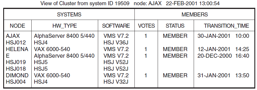
SHOW CLUSTER qualifiers
SHOW CLUSTER commands
A default keypad, which can be redefined
An initialization file to format the display
Command procedures to control the display
SHOW CLUSTER has a number of qualifiers and commands, and a definable keypad that allow you to customize the display. You can rearrange the position of windows, scroll their contents, or change the interval at which the display is updated. This chapter contains reference information for the SHOW CLUSTER qualifiers and commands. Appendix B, "SHOW CLUSTER Keypad Commands" describes how to use the keypad.
Over time, as you determine the most valuable classes and fields of data for the SHOW CLUSTER report, you can create a startup initialization file that establishes your default report format. You can also build command procedures and define a keypad to use while running SHOW CLUSTER interactively.
By customizing SHOW CLUSTER output, you can display only data that is relevant to your installation. Creating the initialization file SHOW_CLUSTER$INIT:SHOW_CLUSTER.INI is described in VSI OpenVMS System Manager's Manual, Volume 2: Tuning, Monitoring, and Complex Systems.
By customizing the SHOW CLUSTER keypad, you can redefine default keypad functions to be more site specific. Using SHOW CLUSTER keypad commands is described in Appendix B, "SHOW CLUSTER Keypad Commands".
7.2. SHOW CLUSTER Usage Summary
SHOW CLUSTER
SHOW CLUSTER — The Show Cluster utility (SHOW CLUSTER) monitors the activity and performance of an OpenVMS Cluster system, and outputs the information to your default terminal or to a specified device or file.
Syntax
SHOW CLUSTER [/qualifier[, . . . ]]
Parameters
None.
Description
$SHOW CLUSTER
$SHOW CLUSTER/CONTINUOUS
In a continuous display, you can control report output with SHOW CLUSTER commands. You can direct SHOW CLUSTER output to a file or device other than to SYS$OUTPUT by specifying the /OUTPUT qualifier with the SHOW CLUSTER command.
To exit from a continuous display and return to the DCL level, enter the EXIT command or press Ctrl/Z. To exit from SHOW CLUSTER without erasing the screen, press Ctrl/C. To interrupt SHOW CLUSTER, press Ctrl/Y.
7.3. SHOW CLUSTER Qualifiers
|
Qualifier |
Description |
|---|---|
|
/BEGINNING=time |
Specifies the time that the SHOW CLUSTER session is to begin. |
|
/CONTINUOUS |
Controls whether SHOW CLUSTER runs as a continuously updating display. |
|
/ENDING=time |
Specifies the time that the SHOW CLUSTER session is to end. |
|
/INTERVAL=seconds |
Specifies the number of seconds that display information remains on the screen before it is updated. |
|
/OUTPUT=file-spec |
Directs the output from SHOW CLUSTER to the specified file instead of the current SYS$OUTPUT device. |
/BEGINNING=time
/BEGINNING=time — Specifies the time that the SHOW CLUSTER session is to begin. You can specify an absolute time, a delta time, or a combination of the two. Observe the syntax rules for time values described in the VSI OpenVMS User's Manual. If you specify a future time, your process is placed in a state of hibernation until the specified time. Use this qualifier with the /OUTPUT and /ENDING qualifiers to run SHOW CLUSTER without direct user intervention.
Syntax
/BEGINNING=time
Parameter
time
You can specify time as an absolute time expressed as [dd-mmm-yyyy[:]] [hh:mm:ss.cc], or a delta time expressed as [dddd-][hh:mm:ss.cc], or a combination of the two. Observe the syntax rules for time values described in the VSI OpenVMS User's Manual.
Examples
$SHOW CLUSTER/BEGINNING=31-OCT-2002:20:30In this example, specifying an absolute time, SHOW CLUSTER produces a single display at 8:30 p.m. on October 31, 2002.
$SHOW CLUSTER/CONTINUOUS/BEGINNING=31-OCT-2002:21:30In this example, specifying an absolute time, SHOW CLUSTER begins a continuous display at 9:30 p.m. on October 31, 2002.
$SHOW CLUSTER/BEGINNING=7-:30In this example, specifying a delta time, SHOW CLUSTER produces a single display 7 days and 30 minutes from now.
/CONTINUOUS
/CONTINUOUS — Controls whether SHOW CLUSTER runs as a continuously updating display. If you omit the qualifier, SHOW CLUSTER produces a single display and returns control to the DCL command level. Running SHOW CLUSTER in the continuous mode allows you to use SHOW CLUSTER commands to control the display.
Syntax
/CONTINUOUS
Example
$SHOW CLUSTER/CONTINUOUS
In this example, SHOW CLUSTER begins to display a continuous report that is updated every 15 seconds.
/ENDING=time
/ENDING=time — Specifies the time that the SHOW CLUSTER session is to end. You can specify an absolute time, a delta time, or a combination of the two. Observe the syntax rules for time values described in the VSI OpenVMS User's Manual. Use this qualifier with the /BEGINNING and /OUTPUT qualifiers to run SHOWCLUSTER without direct user intervention.
Syntax
/ENDING=time
Parameter
time
You can specify time as an absolute time expressed as [dd-mmm-yyyy[:]][hh:mm:ss.cc], or a delta time expressed as [dddd-][hh:mm:s.cc], or a combination of the two. Observe the syntax rules for time values described in the VSI OpenVMS User's Manual.
Example
$SHOW CLUSTER/CONTINUOUS/ENDING=31-OCT-2002:15:30
In this example, SHOW CLUSTER begins a continuous display now and ends the display at 3:30 p.m. on October 31, 2002.
/INTERVAL=seconds
/INTERVAL=seconds — Specifies the number of seconds that display information remains on the screen before it is updated. By default, the interval time is 15 seconds.
Syntax
/INTERVAL=seconds
Parameter
seconds
The number of seconds between display updates.
Example
$SHOW CLUSTER/INTERVAL=5
In this example, SHOW CLUSTER displays a continuous report that is updated every 5 seconds.
/OUTPUT=file-spec
/OUTPUT=file-spec — Directs the output from SHOW CLUSTER to the specified file instead of the current SYS$OUTPUT device. SHOW CLUSTER output is always in printable file format, regardless of the file or device type specified. Output can be up to 132 columns wide and can be sent to any file, terminal, or print device. You can also direct output to a file with the WRITE command.
Syntax
/OUTPUT=file-spec
Parameter
file-spec
The name of the file or device to which SHOW CLUSTER output is directed. The default file name is SHOW_CLUSTER.LIS.
You can direct output to a device other than SYS$OUTPUT by specifying a valid device name.
Example
$SHOW CLUSTER/OUTPUT=[OMALLEY]CLUSTER
In this example, SHOW CLUSTER produces one report and directs it to the file CLUSTER.LIS;1 in the directory OMALLEY.
7.4. SHOW CLUSTER Commands
|
Command Name |
Description |
|---|---|
|
@ (Execute Procedure) |
Executes a command procedure file that contains SHOW CLUSTER commands. |
|
ADD CIRCUITS |
Adds all currently enabled CIRCUITS class fields to the SHOW CLUSTER display. |
|
ADD CLUSTER |
Adds all currently enabled CLUSTER class fields to the SHOW CLUSTER display. |
|
ADD CONNECTIONS |
Adds all currently enabled CONNECTIONS class fields to the SHOW CLUSTER display. Optionally, the command adds connections according to state or name. |
|
ADD COUNTERS |
Adds all currently enabled COUNTERS class fields to the SHOW CLUSTER display. |
|
ADD CREDITS |
Adds all currently enabled CREDITS class fields to the SHOW CLUSTER display. |
|
ADD ERRORS |
Adds all currently enabled ERRORS class fields to the SHOW CLUSTER display. |
|
ADD (Field) |
Enables the display of specific fields of SHOWCLUSTER information. |
|
ADD LOCAL_PORTS |
Adds all currently enabled LOCAL_PORTS class fields to the SHOW CLUSTERS display. |
|
ADD MEMBERS |
Adds all currently enabled MEMBERS class fields to the SHOW CLUSTER display. |
|
ADD SYSTEMS |
Adds all currently enabled SYSTEMS class fields to the SHOW CLUSTER display for all active systems or for selected systems. |
|
DEFINE/KEY |
Associates an equivalence string and set of attributes with a key on the terminal keyboard. |
|
DESELECT |
Terminates the selection of a previously selected window. |
|
EXIT |
Terminates the SHOW CLUSTER display and returns control to the DCL command level. |
|
HELP |
Provides online help information for using SHOW CLUSTER commands, parameters, and qualifiers. Press Ctrl/Z to exit. |
|
INITIALIZE |
Resets the display using the original default values for field names, class names, and field widths. It also restores any systems that were removed from the display by the REMOVE SYSTEMS command. |
|
MOVE |
Moves a selected window to a specified position. |
|
PAN |
Exhibits a wide display area, a part at a time, as though being unrolled. |
|
REFRESH |
Clears the screen, removes extraneous characters, and updates all fields. |
|
REMOVE CIRCUITS |
Removes CIRCUITS class information from the SHOWCLUSTER display. |
|
REMOVE CLUSTER |
Removes CLUSTER class information from the SHOWCLUSTER display. |
|
REMOVE CONNECTIONS |
Removes CONNECTIONS class information from the SHOW CLUSTER display. |
|
REMOVE COUNTERS |
Removes COUNTERS class information from the SHOW CLUSTER display. |
|
REMOVE CREDITS |
Removes CREDITS class information from the SHOW CLUSTER display. |
|
REMOVE ERRORS |
Removes ERRORS class information from the SHOW CLUSTER display. |
|
REMOVE (Field) |
Disables the display of specific fields of SHOW CLUSTER information. |
|
REMOVE LOCAL_PORTS |
Removes LOCAL_PORTS class information from the SHOW CLUSTER display. |
|
REMOVE MEMBERS |
Removes MEMBERS class information from the SHOW CLUSTER display. |
|
REMOVE SYSTEMS |
Removes SYSTEMS class information from the SHOW CLUSTER display. |
|
SAVE |
Allows you to build a startup initialization file or a command procedure that creates the current display so you can restore the display at a later time. |
|
SCROLL |
Scrolls a window. |
|
SELECT |
Designates which window to scroll or move. |
|
SET AUTO_POSITIONING |
Enables or disables the automatic positioning of windows within a display. |
|
SET (Field) |
Modifies the characteristics of particular fields within the display. |
|
SET FUNCTION |
Enables one of the following SHOW CLUSTER functions:EDIT, MOVE, PAN, or SCROLL. |
|
SET INTERVAL |
Changes the interval time between display updates. The default interval time is 15 seconds. |
|
SET SCREEN |
Sets the terminal to a display of up to 511 columns. |
|
WRITE |
Outputs the current display to a file that can be printed on a hard copy device. |
@ (Execute Procedure)
@ (Execute Procedure) — Executes a command procedure file that contains SHOW CLUSTER commands.
Syntax
@ file-spec
Parameter
file-spec
Specifies the name of the file that contains the commands to be executed. If you omit the file type, the default file type .COM is used. No wildcard characters are allowed in the file specification.
Description
The execute procedure (@) command allows you to execute a set of SHOW CLUSTER commands that are contained in a file. For example, a command procedure file might contain a set of commands to customize a SHOW CLUSTER display. You can use any valid SHOW CLUSTER commands in the command procedure. You can nest command procedures up to 16 levels deep.
SHOW CLUSTER looks for the command procedure in the directory specified by the logical name SHOW_CLUSTER$INIT. If SHOW_CLUSTER$INIT is not defined or does not include a directory specification, the utility looks for the command procedure in the current default directory.
Example
COMMAND>@MYFILE
This command executes the command procedure MYFILE.COM. Because no file type is specified, the file type defaults to .COM.
ADD CIRCUITS
ADD CIRCUITS — Adds all currently enabled CIRCUITS class fields to the SHOW CLUSTER display. The CIRCUITS class contains information about the virtual circuits on systems in the cluster.
Syntax
ADD CIRCUITS [/qualifier[, . . . ]]
Parameters
None.
Qualifiers
- /ALL
Specifies that all fields in this class are to be added to the display.
- /TYPE=ALL
Specifies that all types of circuits be included in the display, including formative, open, and closing circuits.
- /TYPE=OPEN
/TYPE=NOOPEN Controls whether either open circuits or nonopen circuits are added to the display.
Description
- RPORT_NUM – remote port number
- RP_TYPE – remote port type
- CIR_STATE – circuit state
For a list of all CIRCUITS class fields, see Table 7.2, ''CIRCUITS Class Fields''.
Use the ADD CIRCUITS command together with the REMOVE CIRCUITS command to turn the display of CIRCUITS class information on and off. If you remove the CIRCUITS class from the display and add it again without changing any fields, all of the same fields are displayed again. If, however, you remove the CIRCUITS class and add new CIRCUITS class fields, all previously enabled fields are disabled, and only the newly added fields are displayed.
Examples
COMMAND>ADD CIRCUITSThis command adds CIRCUITS class information to the display. This information includes all types of circuits for all enabled CIRCUITS class fields.
COMMAND>ADD CIRCUITS/TYPE=OPENThis command adds all open circuits to the SHOWCLUSTER display.
COMMAND>REMOVE CIRCUITSCOMMAND>ADD RP_OWNERCOMMAND>REMOVE CIRCUITS. . .COMMAND>ADD CIRCUITSThe ADD CIRCUITS command in this example sequence adds CIRCUITS class information to the SHOW CLUSTER display. The REMOVE CIRCUITS command removes the CIRCUITS class from the display.
The ADD RP_OWNER command adds the CIRCUITS class field RP_OWNER to the display. As a result, all other CIRCUITS class fields are disabled. When the CIRCUITS class is removed and added again, only the RP_OWNER field is displayed.
ADD CLUSTER
ADD CLUSTER — Adds all currently enabled CLUSTER class fields to the SHOW CLUSTER display.
Syntax
ADD CLUSTER
Parameters
None.
Qualifier
- /ALL
Specifies that all fields in this class are to be added to the display.
Description
- CL_EXPECTED_VOTES – number of cluster votes expected
- CL_QUORUM – cluster quorum
- CL_VOTES – cluster votes
- QF_VOTE – quorum disk contributes a vote
- CL_MEMBERS – current cluster members
- FORMED – when quorum was formed
- LAST_TRANSITION – last change in cluster membership
For a list of all CLUSTER class fields, see Table 7.3, ''CLUSTER Class Fields''.
Use the ADD CLUSTER command with the REMOVE CLUSTER command to turn the display of CLUSTER class information on and off. If you remove the CLUSTER class from the display and add it again without changing any fields, all of the same fields are displayed again. If, however, you remove the CLUSTER class and add new CLUSTER class fields, all previously enabled fields are disabled, and only the newly added fields are displayed.
Examples
COMMAND>ADD CLUSTERThis command adds CLUSTER class information to the display. This information includes all enabled CLUSTER class fields.
COMMAND>REMOVE CLUSTERCOMMAND>ADD CL_QUORUMCOMMAND>REMOVE CLUSTER. . .COMMAND>ADD CLUSTERThe ADD CLUSTER command in this example adds CLUSTER class information to the SHOW CLUSTER display. The first command in the sequence removes the CLUSTER class from the display. The second command, ADD CL_QUORUM, adds the CLUSTER class field CL_QUORUM to the display. As a result, all other CLUSTER class fields are disabled. When the CLUSTER class is removed and added again, only the CL_QUORUM field is displayed.
ADD CONNECTIONS
ADD CONNECTIONS — Adds all currently enabled CONNECTIONS class fields to the SHOW CLUSTER display. Optionally, the command adds connections according to state or name.
Syntax
ADD CONNECTIONS [/qualifier[, . . . ]]
Parameters
None.
Qualifiers
- /ALL
Specifies that all fields in this class are to be added to the display.
- /NAME=ALL
Restores processes removed from the display with the command REMOVECONNECTIONS/NAME=local-process-name.
- /NAME=local-process-name
Adds the connection associated with the specified local process name, as displayed in the LOC_PROC_NAME field of the CONNECTIONS class.
A local process name can contain up to 16 characters. If the name is abbreviated, SHOW CLUSTER adds all local process names matching the abbreviation.
- /TYPE=ALL
Specifies that all types of connections on each circuit are displayed. For a listing of the possible states a connection can be in, see the description of the CON_STATE field in Table 7.4, ''CONNECTIONS Class Fields''. By default, the ADD CONNECTIONS command without any qualifiers displays all types of connections.
- /TYPE=OPEN
/TYPE=NOOPEN Controls whether connections in the open state or the non-openstate are to be added to the SHOW CLUSTER display.
Description
The ADD CONNECTIONS command adds CONNECTIONS class information to the SHOWCLUSTER display. This information includes data for all currently enabled fields in the CONNECTIONS class.
- LOC_PROC_NAME – local process name
- CON_STATE – connection state
For a list of all CONNECTIONS class fields, see Table 7.4, ''CONNECTIONS Class Fields''.
Use the ADD CONNECTIONS command together with the REMOVE CONNECTIONS command to turn the display of CONNECTIONS class information on and off. If you remove the CONNECTIONS class from the display and add it again without changing any fields, all of the same fields are displayed again. If, however, you remove the CONNECTIONS class and add new CONNECTIONS class fields, all previously enabled fields are disabled, and only the newly added fields are displayed.
Examples
COMMAND>ADD CONNECTIONSThis command adds CONNECTIONS class information to the display. This information includes all enabled CONNECTIONS class fields.
COMMAND>ADD CONNECTIONS/NAME=(MSCP$DISK,VMS$VMScluster)This command adds all connections associated with the process MSCP$DISK and the process VMS$VMScluster to the SHOWCLUSTER display.
COMMAND>ADD CONNECTIONS/TYPE=OPENThis command adds all open connections to the SHOW CLUSTER display.
COMMAND>REMOVE CONNECTIONSCOMMAND>ADD SCS_STATECOMMAND>REMOVE CONNECTIONS. . .COMMAND>ADD CONNECTIONSThe ADD CONNECTIONS command in this example adds CONNECTIONS class information to the SHOW CLUSTER display. The first command in the sequence removes the CONNECTIONS class from the display. The second command, ADDSCS_STATE, adds the CONNECTIONS class field SCS_STATE to the display. As a result, all other CONNECTIONS class fields are disabled. When the CONNECTIONS class is removed and added again, only the SCS_STATE field is displayed.
ADD COUNTERS
ADD COUNTERS — Adds all currently enabled COUNTERS class fields to the SHOW CLUSTER display.
Syntax
ADD COUNTERS
Parameters
None.
Qualifier
- /ALL
Specifies that all fields in this class are to be added to the display.
Description
The ADD COUNTERS command adds COUNTERS class information to the SHOW CLUSTER display. This information includes data for all currently enabled fields in the COUNTERS class.
- DGS_SENT – datagrams sent
- DGS_RCVD – datagrams received
- MSGS_SENT – messages sent
- MSGS_RCVD – messages received
For a list of all COUNTERS class fields, see Table 7.5, ''COUNTERS Class Fields''.
Use the ADD COUNTERS command together with the REMOVE COUNTERS command to turn the display of COUNTERS class information on and off. If you remove the COUNTERS class from the display and add it again without changing any fields, all of the same fields are displayed again. If, however, you remove the COUNTERS class and add new COUNTERS class fields, all previously enabled fields are disabled, and only the newly added fields are displayed.
Examples
COMMAND>ADD COUNTERSThis command adds COUNTERS class information to the display. This information includes all enabled COUNTERS class fields.
COMMAND>REMOVE COUNTERSCOMMAND>ADD MSGS_SENTCOMMAND>REMOVE COUNTERS. . .COMMAND>ADD COUNTERSThe ADD COUNTERS command in this example sequence adds COUNTERS class information to the SHOW CLUSTER display. The first command removes the COUNTERS class from the display. The second command, ADD MSGS_SENT, adds the COUNTERS class field MSGS_SENT to the display. As a result, all other COUNTERS class fields are disabled. When the COUNTERS class is removed and added again, only the MSGS_SENT field is displayed.
ADD CREDITS
ADD CREDITS — Adds all currently enabled CREDITS class fields to the SHOW CLUSTER display.
Syntax
ADD CREDITS
Parameters
None.
Qualifier
- /ALL
Specifies that all fields in this class are to be added to the display. By default, the ADD CREDITS command, used without any qualifiers, displays all the CREDITS class fields.
Description
The ADD CREDITS command adds CREDITS class information to the SHOW CLUSTER display. This information includes data for all currently enabled fields in the CREDITS class.
By default, all CREDITS class fields are enabled. For a list of all CREDITS class fields, see Table 7.6, ''CREDITS Class Fields''.
Use the ADD CREDITS command together with the REMOVE CREDITS command to turn the display of CREDITS class information on and off. If you remove the CREDITS class from the display and then add it again without changing any fields, all of the same fields are displayed again. If, however, you remove the CREDITS class and add new CREDITS class fields, all previously enabled fields are disabled, and only the newly added fields are displayed.
Examples
COMMAND>ADD CREDITSThis command adds CREDITS class information to the display. This information includes all enabled CREDITS class fields.
COMMAND>REMOVE CREDITSCOMMAND>ADD MIN_RECCOMMAND>REMOVE CREDITS. . .COMMAND>ADD CREDITSThe ADD CREDITS command in this example sequence adds CREDITS class information to the SHOW CLUSTER display. The first command removes the CREDITS class from the display. The second command, ADD MIN_REC, adds the CREDITS class field MIN_REC to the display. As a result, all other CREDITS class fields are disabled. When the CREDITS class is removed and added again, only the MIN_REC field is displayed.
ADD ERRORS
ADD ERRORS — Adds all currently enabled ERRORS class fields to the SHOW CLUSTER display.
Syntax
ADD ERRORS
Parameters
None.
Qualifier
- /ALL
Specifies that all fields in this class are to be added to the display. By default, ADD ERRORS, used without any field qualifiers, displays all the fields in the ERRORS class.
Description
The ADD ERRORS command adds ERRORS class information to the SHOW CLUSTER display. This information includes data for all currently enabled fields in the ERRORS class.
By default, all ERRORS class fields are enabled. For a list of all ERRORS class fields, see Table 7.7, ''ERRORS Class Fields''.
Use the ADD ERRORS command together with the REMOVE ERRORS command to turn the display of ERRORS class information on and off. If you remove the ERRORS class from the display and add it again without changing any fields, all of the same fields are displayed again. If, however, you remove the ERRORS class and add new ERRORS class fields, all previously enabled fields are disabled, and only the newly added fields are displayed.
Examples
COMMAND>ADD ERRORSThis command adds ERRORS class information to the display. This information includes all enabled ERRORS class fields.
COMMAND>REMOVE ERRORSCOMMAND>ADD ERT_MAXCOMMAND>REMOVE ERRORS. . .COMMAND>ADD ERRORSThe ADD ERRORS command in this example sequence adds ERRORS class information to the SHOW CLUSTER display. The first command removes the ERRORS class from the display. The second command, ADD ERT_MAX, adds the ERRORS class field ERT_MAX to the display. As a result, all other ERRORS class fields are disabled. When the ERRORS class is removed and added again, only the ERT_MAX field is displayed.
ADD (Field)
ADD (Field) — Enables the display of specific fields of SHOW CLUSTER information.
Syntax
ADD field-name[, . . . ]
CIRCUITS
The CIRCUITS class contains information about the virtual circuits on a system, such as the local port name, the remote port type and number, the number of connections on the circuit, and the circuit state.
See Table 7.2, ''CIRCUITS Class Fields'' for a table containing the fields in the CIRCUITS class.
CLUSTER
The CLUSTER class contains general information about the cluster, such as the time it was formed, the last time a system joined or left the cluster, and the cluster quorum.
See Table 7.3, ''CLUSTER Class Fields'' for a table containing the fields in the CLUSTER class.
CONNECTIONS
The CONNECTIONS class contains information about connections established over a virtual circuit, such as the names of the local and remote processes, and the state of the connection.
See Table 7.4, ''CONNECTIONS Class Fields'' for a table containing the fields in the CONNECTIONS class.
COUNTERS
The COUNTERS class displays statistics on connection traffic, such as the number of application datagrams or the number of application messages that have been sent or received.
See Table 7.5, ''COUNTERS Class Fields'' for a table containing the fields in the COUNTERS class.
CREDITS
The CREDITS class displays the send and receive credit counts for each connection.
See Table 7.6, ''CREDITS Class Fields'' for a table containing the fields in the CREDITS class.
ERRORS
The ERRORS class displays a count of the errors on each port, along with information about the feasibility of reinitializing a port.
See Table 7.7, ''ERRORS Class Fields'' for a table containing the fields in the ERRORS class.
LOCAL_PORTS
The LOCAL_PORTS class displays information about the local system interface to the cluster, such as the name, number, and status of each port, and the number of entries in the queues associated with each port.
See Table 7.8, ''LOCAL_PORTS Class Fields'' for a table containing the fields in the LOCAL_PORTS class.
MEMBERS
The MEMBERS class contains information about active systems in the cluster, such as their identification numbers and membership status.
See Table 7.9, ''MEMBERS Class Fields'' for a table containing the fields in the MEMBERS class.
SYSTEMS
The SYSTEMS class lists information about all systems in the cluster, such as their identification numbers, node names, hardware types, and software versions.
See Table 7.10, ''SYSTEMS Class Fields'' for a table containing the fields in the SYSTEMS class.
Description
The ADD (Field) command enables and adds specific fields of information to a SHOW CLUSTER display. When you add a field for a class that is not currently being displayed, the class heading of that field is added to the display. The qualifier /ALL on any ADD (Class) command adds all fields in the class to the display.
To remove a field from the SHOW CLUSTER display, enter the REMOVE (Field) command.
Examples
COMMAND>ADD SENDThis command enables the CREDITS class field SEND and adds it to the SHOW CLUSTER display.
COMMAND>ADD REM_STATE,REM_CONID,LOC_CONIDThis command enables the CIRCUITS class field REM_STATE and the CONNECTIONS class fields REM_CONID and LOC_CONID, and adds them to the SHOW CLUSTER display.
ADD LOCAL_PORTS
ADD LOCAL_PORTS — Adds all currently enabled LOCAL_PORTS class fields to the SHOW CLUSTER display.
Syntax
ADD LOCAL_PORTS
Parameters
None.
Qualifier
- /ALL
Specifies that all fields in this class are to be added to the display.
Description
The ADD LOCAL_PORTS command adds LOCAL_PORTS class information to the SHOWCLUSTER display. This information includes data for all currently enabled fields in the LOCAL_PORTS class.
- NAME
- LP_STATUS – port status
- PORT_NUM – port number
- DGS_FREE – free datagrams queued
- MSGS_FREE – free messages queued
- OPEN_CIRCS – open circuits
- FORM_CIRCS – formative circuits
For a list of all LOCAL_PORTS class fields, see Table 7.8, ''LOCAL_PORTS Class Fields''.
Use the ADD LOCAL_PORTS command with the REMOVE LOCAL_PORTS command to turn the display of LOCAL_PORTS class information on and off. If you remove the LOCAL_PORTS class from the display and add it again without changing any fields, all of the same fields are displayed again. If, however, you remove the LOCAL_PORTS class and add new LOCAL_PORTS class fields, all previously enabled fields are disabled, and only the newly added fields are displayed.
Examples
COMMAND>ADD LOCAL_PORTSThis command adds LOCAL_PORTS class information to the display. This information includes all enabled LOCAL_PORTS class fields.
COMMAND>REMOVE LOCAL_PORTSCOMMAND>ADD LB_STATUSCOMMAND>REMOVE LOCAL_PORTS. . .COMMAND>ADD LOCAL_PORTSThe ADD LOCAL_PORTS command in this example sequence adds LOCAL_PORTS class information to the SHOW CLUSTER display. The first command removes the LOCAL_PORTS class from the display. The second command, ADD LB_STATUS, adds the LOCAL_PORTS class field LB_STATUS to the display. As a result, all other LOCAL_PORTS class fields are disabled. When the LOCAL_PORTS class is removed and added again, only the LB_STATUS field is displayed.
ADD MEMBERS
ADD MEMBERS — Adds all currently enabled MEMBERS class fields to the SHOW CLUSTER display.
Syntax
ADD MEMBERS
Parameters
None.
Qualifier
- /ALL
Specifies that all fields in this class are to be added to the display.
Description
The ADD MEMBERS command adds MEMBERS class information to the SHOW CLUSTER display. This information includes data for all currently enabled fields in the MEMBERS class.
By default, only the STATUS field is enabled. For a list of all MEMBERS class fields, see Table 7.9, ''MEMBERS Class Fields''.
Use the ADD MEMBERS command with the REMOVE MEMBERS command to turn the display of MEMBERS class information on and off. If you remove the MEMBERS class from the display and add it again without changing any fields, all of the same fields are displayed again. If, however, you remove the MEMBERS class and add new MEMBERS class fields, all previously enabled fields are disabled, and only the newly added fields are displayed.
Examples
COMMAND>
ADD MEMBERSThis command adds MEMBERS class information to the display. This information includes all enabled MEMBERS class fields.
COMMAND>REMOVE MEMBERSCOMMAND>ADD VOTESCOMMAND>REMOVE MEMBERS. . .COMMAND>ADD MEMBERSThe ADD MEMBERS command in this example sequence adds MEMBERS class information to the SHOW CLUSTER display. The first command removes the MEMBERS class from the display. The second command, ADD VOTES, adds the MEMBERS class field VOTES to the display. As a result, all other MEMBERS class fields are disabled. When the MEMBERS class is removed and added again, only the VOTES field is displayed.
ADD SYSTEMS
ADD SYSTEMS — Adds all currently enabled SYSTEMS class fields to the SHOW CLUSTER display for all active systems or for selected systems.
Syntax
ADD SYSTEMS [/qualifier[, . . . ]]
Parameters
None.
Qualifiers
- /ALL
Specifies that all fields in the SYSTEMS class are to be added to the display.
- /ID=ALL
Restores the display after selectively removing systems by ID.
- /ID=system-id
Specifies, by system identification number, systems to be added to the SHOW CLUSTER display. The system-id can be any identification number displayed in the SYS_ID field of the SYSTEMS class. When using a hexadecimal value for an identifier, precede the number with the characters %X.
The /ID qualifier affects all information displayed about the specified system, not just information in the SYSTEMS class display.
- /NODE=ALL
Restores the display after selectively removing systems by node name.
- /NODE=node-name
Specifies, by node name, systems to be added to the SHOW CLUSTER display. The node-name can be any node displayed in the NODE field of the SYSTEMS class, and it can be enclosed in quotation marks. The /NODE qualifier affects all information displayed about the specified node, not just information in the SYSTEMS class display.
- /TYPE=ALL
Restores the display after selectively removing systems by type.
- /TYPE=hardware-type
Specifies, by hardware type, systems to be added to the SHOWCLUSTER display. You can specify any of the types shown in the HW_TYPE field, and you must enclose the type in quotation marks; for example, "VAX 8800". Because the quoted text may be abbreviated, it is possible, for example, to add VAXstation II and VAXstation 2000systems with a single command. Multiple types may be specified if enclosed in parentheses and separated by commas. Hardware types are not case sensitive.
The /TYPE qualifier affects all information displayed about the specified hardware type, not just information in the SYSTEMS class display.
Description
- NODE
- SOFTWARE
For a list of all SYSTEMS class fields, see Table 7.10, ''SYSTEMS Class Fields''.
Use the ADD SYSTEMS command with the REMOVE SYSTEMS command to turn the display of SYSTEMS class information on and off. If you remove the SYSTEMS class from the display and add it again without changing any fields, all of the same fields are displayed again. If, however, you remove the SYSTEMS class and add new SYSTEMS class fields, all previously enabled fields are disabled, and only the newly added fields are displayed.
Examples
COMMAND>ADD SYSTEMSThis command adds SYSTEMS class information to the display. This information includes all enabled SYSTEMS class fields.
COMMAND>ADD SYSTEMS/NODE=(PISHTA,ELF)This command adds the nodes PISHTA and ELF to the SHOW CLUSTER display, reporting all currently enabled information about the nodes.
COMMAND>ADD SYSTEMS/TYPE=("VAX 8800","MicroVAX 2000")This command adds all VAX 8800 and MicroVAX 2000 processors to the SHOW CLUSTER display, reporting all currently enabled information about those hardware types.
COMMAND>REMOVE SYSTEMSCOMMAND>ADD SYS_IDCOMMAND>REMOVE SYSTEMS. . .COMMAND>ADD SYSTEMSThe ADD SYSTEMS command in this example sequence adds SYSTEMS class information to the SHOW CLUSTER display. The first command removes the SYSTEMS class from the display. The second command, ADD SYS_ID, adds the SYSTEMS class field SYS_ID to the display. As a result, all other SYSTEMS class fields are disabled. When the SYSTEMS class is removed and added again, only the SYS_ID field is displayed.
DEFINE/KEY
DEFINE/KEY — Associates an equivalence string and set of attributes with a key on the terminal keyboard. The /KEY qualifier is required.
Syntax
DEFINE/KEY key-name equivalence-string
Parameters
key-name
|
Key Name |
LK201 |
VT100 |
VT52 |
|---|---|---|---|
|
PF1 |
PF1 |
PF1 |
[blue] |
|
PF2 |
PF2 |
PF2 |
[red] |
|
PF3 |
PF3 |
PF3 |
[gray] |
|
PF4 |
PF4 |
PF4 |
- - |
|
KP0, KP1 to KP9 |
0, 1 to 9 |
0, 1 to 9 |
0, 1 to 9 |
|
PERIOD |
. |
. |
. |
|
COMMA |
, |
, |
n/a |
|
MINUS |
- |
- |
n/a |
|
ENTER |
Enter |
ENTER |
ENTER |
|
Find (E1) |
Find |
- - |
- - |
|
Insert Here (E2) |
Insert Here |
- - |
- - |
|
Remove (E3) |
Remove |
- - |
- - |
|
Select (E4) |
Select |
- - |
- - |
|
Prev Screen (E5) |
Prev Screen |
- - |
- - |
|
Next Screen (E6) |
Next Screen |
- - |
- - |
|
HELP |
Help |
- - |
- - |
|
DO |
Do |
- - |
- - |
|
F17 to F20 |
F17 to F20 |
- - |
- - |
equivalence-string
Specifies the string to be processed when you press the key. The string can be a SHOW CLUSTER command. If the string contains any spaces, enclose the equivalence string in quotation marks.
Qualifiers
- /ECHO (default)
/NOECHO Determines whether the equivalence string is displayed on your screen after the key has been pressed. You cannot use /NOECHO with the/NOTERMINATE qualifier.
- /ERASE
/NOERASE (default) Determines whether the current line is erased before the key translation is inserted.
- /IF_STATE=(state-name, . . . )
/NOIF_STATE Specifies a list of one or more states, one of which must take effect for the key definition to be in effect. If you omit the /IF_STATE qualifier or use /NOIF_STATE, the current state is used.
- /LOCK_STATE
/NOLOCK_STATE (default) Specifies that the state set by the /SET_STATE qualifier remain in effect until explicitly changed. If you use the /NOLOCK_STATE qualifier, the state set by /SET_STATE is in effect only for the next definable key that you press or for the next read-terminating character that you type.
The /LOCK_STATE qualifier can be specified only with the /SET_STATE qualifier.
- /LOG (default)
/NOLOG Controls whether the system displays a message indicating that the key definition has been successfully created.
- /SET_STATE=state-name
/NOSET_STATE (default) Causes the specified state-name to be set when the key is pressed. The state name can be any alphanumeric string.
If you omit the SET_STATE qualifier or use /NOSET_STATE, the current state that was locked remains in effect. If you have not included this qualifier with a key definition, use the DCL command SET KEY to change the current state.
- /TERMINATE
/NOTERMINATE (default) Specifies whether the current equivalence string is to be terminated (that is, processed) when the key is pressed. Pressing Return has the same effect as using /TERMINATE.
The /NOTERMINATE qualifier allows you to create key definitions that insert text into command lines, after prompts, or into other text that you are typing.
Description
The DEFINE/KEY command enables you to assign definitions to the keys on certain terminals. The terminals include VT52s, the VT100 series, and terminals with LK201 keyboards, such as the VT200 series.
The equivalence string definition can contain different types of information. Definitions can consist of SHOW CLUSTER commands. When you define a key to insert a text string, use the /NOTERMINATE qualifier so that you can continue typing more data after the string has been inserted.
In most instances you will want to take advantage of the echo feature. The default setting is /ECHO. With the /ECHO qualifier set, the key definition is displayed on the screen each time you press the key.
You can use the /STATE qualifier to increase the number of key definitions available on your terminal. The same key can be assigned any number of definitions as long as each definition is associated with a different state. State names can contain any alphanumeric characters, dollar signs, and underscores. Generally, you want to create a state name that is easy to remember and type and, if possible, reminds you of the types of definitions you created for that state.
Example
Command>DEFINE/KEY PF3 "LOCAL_PORT"/NOTERMINATE
This command defines the PF3 key on the keypad to output the "LOCAL_PORT" text string. This key could be used with the ADD key to form the ADD LOCAL_PORT command.
DESELECT
DESELECT — Terminates the selection of a previously selected window. When the DESELECT command is entered after a MOVE command, SHOW CLUSTER completes the move operation when it deselects the window. See also the MOVE and SELECT commands for related information.
Syntax
DESELECT
Parameters
None.
Qualifiers
None.
Example
Command>DESELECT
When you send the DESELECT command, the previously selected window is deselected and the window is no longer highlighted.
EXIT
EXIT — Terminates the SHOW CLUSTER display and returns control to the DCL command level. You can also press Ctrl/Z to exit at any time.
Syntax
EXIT
Parameters
None.
Qualifiers
None.
Example
COMMAND>EXIT
This command terminates the SHOW CLUSTER display and returns control to the DCL command level.
HELP
HELP — Provides online help information to use SHOW CLUSTER commands, parameters, and qualifiers. Press Ctrl/Z to exit.
Syntax
HELP [keyword . . . ]
Parameter
keyword
Specifies the command, parameter, or qualifier for which help information is to be displayed. If you omit the keyword, HELP displays a list of available help topics, and prompts you for a particular keyword.
Qualifiers
None.
Examples
COMMAND>HELP INITIALIZEThis command displays help information about the SHOWCLUSTER command INITIALIZE.
COMMAND>HELP FIELDSThis command displays help information about the valid field names that you can specify with the ADD, REMOVE, and SET commands.
INITIALIZE
INITIALIZE — Resets the display using the original default values for field names, class names, and field widths. It also restores any systems that were removed from the display by the REMOVE SYSTEMS command.
Syntax
INITIALIZE
Parameters
None.
Qualifiers
None.
Description
The INITIALIZE command resets the SHOW CLUSTER display to its default setting, consisting of the SCS window with data from the SYSTEMS class and the MEMBERS class. The report shows the node name, the software version, and the status of cluster members.
If you save a series of commands in an initialization file, using the SAVE command, SHOW CLUSTER automatically inserts an INITIALIZE command at the beginning of the file. Any command procedure that you build should start with the INITIALIZE command. In this way, you always tailor the display from a known state.
Example
COMMAND>INITIALIZE
This command resets the current display to the default display and restores any systems that were removed from the display.
MOVE
MOVE — Moves a selected window to a specified position.
Syntax
MOVE direction value
Parameters
direction
- UP
- DOWN
- RIGHT
- LEFT
value
Number of columns or lines the window is to be moved. You must specify a numeric value from 1 to 511. If you do not enter a number for this parameter, SHOW CLUSTER prompts you for one.
Qualifiers
None.
Description
The MOVE command allows you to reposition a window manually on the display screen. With one window in the SHOW CLUSTER display, you can enter MOVE commands directly. However, with multiple windows, you must select the appropriate window (SELECT window-name) before invoking MOVE commands. The MOVE command implicitly disables AUTO_POSITIONING.
To move a selected window, either enter MOVE commands at the command prompt or use the arrow keys defined as MOVE commands. Entering the command SETFUNCTION MOVE redefines the direction keys as MOVE UP 1, MOVE DOWN 1, MOVERIGHT 1, and MOVE LEFT 1, respectively.
When you enter a MOVE command, the window changes position by column (horizontally), or by line (vertically). An empty frame appears around the new window position. When you are satisfied with the position of the window, enter the DESELECT command, which moves the window to the new position. Entering another SELECT command before the previous window has been deselected also moves the window to its new position.
Note
If you set the function to MOVE, the arrow keys are no longer defined to perform DCL line-mode editing. Only one function can be enabled at a time, using the SET FUNCTION command.
Example
Command>SELECT CLUSTERCommand>MOVE RIGHT 10Command>DESELECT
The command sequence in this example moves the CLUSTER window 10 columns to the right.
PAN
PAN — Exhibits a wide display area, a part at a time, as though being unrolled.
Syntax
PAN direction value
Parameters
direction
- UP
- DOWN
- RIGHT
- LEFT
value
Number of columns or lines the display is to be panned. You must specify a numeric value from 1 to 511. If you do not enter a number for this parameter, SHOW CLUSTER prompts you for one.
Description
The PAN commands rotate the entire display by column (horizontally) and by line (vertically). A portion of the display that extends beyond the limits of the screen can be brought into view.
The display moves in the opposite direction from that specified by the PAN command. In other words, a PAN LEFT 10 command moves the display 10 columns to the right, similar to the effect of panning a camera over a landscape.
Note
If you set the function to PAN, the arrow keys are no longer defined to perform DCL line-mode editing. Only one function can be enabled at a time, using the SET FUNCTION command.
Example
Command>PAN DOWN 10
This command pans the display 10 lines.
REFRESH
REFRESH — Clears the screen, removes extraneous characters, and updates all fields. Pressing Ctrl/W has the same effect as entering REFRESH.
Syntax
REFRESH
Parameters
None.
Qualifiers
None.
Example
Command>REFRESH
This command clears the screen, removes extraneous characters, and updates all fields.
REMOVE CIRCUITS
REMOVE CIRCUITS — Removes CIRCUITS class information from the SHOW CLUSTER display.
Syntax
REMOVE CIRCUITS [/qualifier[, . . . ]]
Parameter
None.
Qualifiers
- /TYPE=ALL
Specifies that all types of circuits on each system be removed from the display, including formative, open, and closing circuits. If you specify the REMOVE CIRCUITS command without any qualifiers, all types of circuits are removed from the display by default.
- /TYPE=OPEN
/TYPE=NOOPEN Controls whether open circuits or non-open circuits are removed from the display.
Description
The REMOVE CIRCUITS command removes CIRCUITS class information from the SHOWCLUSTER display. CIRCUITS class information includes data for all currently enabled fields in the CIRCUITS class.
For a list of valid CIRCUITS class fields, see Table 7.2, ''CIRCUITS Class Fields''.
Examples
COMMAND>REMOVE CIRCUITSThis command removes all currently enabled CIRCUITS class fields from the display.
COMMAND>REMOVE CIRCUITS/TYPE=OPENThis command removes all Open circuits from the display.
REMOVE CLUSTER
REMOVE CLUSTER — Removes CLUSTER class information from the SHOW CLUSTER display.
Syntax
REMOVE CLUSTER
Parameters
None.
Qualifiers
None.
Description
The REMOVE CLUSTER command removes CLUSTER class information from the SHOWCLUSTER display. CLUSTER class information includes data for all currently enabled fields in the CLUSTER class.
For a list of valid CLUSTER class fields, see Table 7.3, ''CLUSTER Class Fields''.
Example
COMMAND>REMOVE CLUSTER
This command removes all currently enabled CLUSTER class fields from the SHOW CLUSTER display.
REMOVE CONNECTIONS
REMOVE CONNECTIONS — Removes CONNECTIONS class information from the SHOW CLUSTER display.
Syntax
REMOVE CONNECTIONS [/qualifier[, . . . ]]
Parameters
None.
Qualifiers
- /NAME=ALL
Removes all connections currently displayed by SHOW CLUSTER. This qualifier allows you to clear the display before adding specific connection information with the command ADD CONNECTIONS/NAME=local-process-name.
- /NAME=local-process-name
Specifies the local process name of connections that are to be removed from the display. A local process name appears in the LOC_PROC_NAME field; it can be up to 16 characters in length. If the local process name is abbreviated, SHOW CLUSTER removes all local process names matching the abbreviation.
- /TYPE=ALL
Specifies that all types of connections on each circuit be removed from the SHOW CLUSTER display.
- /TYPE=OPEN
/TYPE=NOOPEN Controls whether connections in the open or non-open state are removed from the SHOW CLUSTER display.
Description
The REMOVE CONNECTIONS command removes CONNECTIONS class information from the SHOW CLUSTER display. CONNECTIONS class information includes data for all currently enabled fields in the CONNECTIONS class.
For a list of valid CONNECTIONS class fields, see Table 7.4, ''CONNECTIONS Class Fields''.
Examples
COMMAND>REMOVE CONNECTIONSThis command removes all currently enabled CONNECTIONS class fields from the SHOW CLUSTER display.
COMMAND>REMOVE CONNECTIONS/NAME=(VMS$DISK_CL_DRVR,VMS$TAPE_CL_DRVR)This command removes the CONNECTIONS class fields associated with the local process names VMS$DISK_CL_DRVR and VMS$TAPE_CL_DRVR from the SHOW CLUSTER display.
COMMAND>REMOVE CONNECTIONS/TYPE=OPENThis command removes all Open connections from the SHOW CLUSTER display.
REMOVE COUNTERS
REMOVE COUNTERS — Removes COUNTERS class information from the SHOW CLUSTER display.
Syntax
REMOVE COUNTERS
Parameters
None.
Qualifiers
None.
Description
The REMOVE COUNTERS command removes COUNTERS class information from the SHOWCLUSTER display. COUNTERS class information includes data for all currently enabled fields in the COUNTERS class.
For a list of valid COUNTERS class fields, see Table 7.5, ''COUNTERS Class Fields''.
Example
COMMAND>REMOVE COUNTERS
This command removes all currently enabled COUNTERS class fields from the SHOW CLUSTER display.
REMOVE CREDITS
REMOVE CREDITS — Removes CREDITS class information from the SHOW CLUSTER display.
Syntax
REMOVE CREDITS
Parameters
None.
Qualifiers
None.
Description
The REMOVE CREDITS command removes CREDITS class information from the SHOWCLUSTER display. CREDITS class information includes data for all currently enabled fields in the CREDITS class.
For a list of valid CREDITS class fields, see Table 7.6, ''CREDITS Class Fields''.
Example
COMMAND>REMOVE CREDITS
This command removes all currently enabled CREDITS class fields from the SHOW CLUSTER display.
REMOVE ERRORS
REMOVE ERRORS — Removes ERRORS class information from the SHOW CLUSTER display.
Syntax
REMOVE ERRORS
Parameters
None.
Qualifiers
None.
Description
The REMOVE ERRORS command removes ERRORS class information from the SHOWCLUSTER display. ERRORS class information includes data for all currently enabled fields in the ERRORS class.
For a list of valid ERRORS class fields, see Table 7.7, ''ERRORS Class Fields''.
Example
COMMAND>REMOVE ERRORS
This command removes all currently enabled ERRORS class fields from the SHOW CLUSTER display.
REMOVE (Field)
REMOVE (Field) — Disables the display of specific fields of SHOW CLUSTER information.
Syntax
REMOVE field-name[, . . . ]
Parameter
field-name
Specifies one or more fields of information to be removed from the display of a particular class. If you specify more than one field name, insert a comma between each one.
For a list of valid field names, see Section 7.1, ''SHOW CLUSTER Description''.
Qualifiers
None.
Examples
COMMAND>REMOVE SOFTWAREThis command removes the SYSTEMS class SOFTWARE field from the display.
COMMAND>REMOVE SOFTWARE,RP_TYPE,CON_STATEThis command removes the SOFTWARE, RP_TYPE, and CON_STATE fields from the SHOW CLUSTER display.
REMOVE LOCAL_PORTS
REMOVE LOCAL_PORTS — Removes LOCAL_PORTS class information from the SHOW CLUSTER display.
Syntax
REMOVE LOCAL_PORTS
Parameters
None.
Qualifiers
None.
Description
The REMOVE LOCAL_PORTS command removes LOCAL_PORTS class information.
For a list of valid LOCAL_PORTS class fields, see Table 7.8, ''LOCAL_PORTS Class Fields''.
Example
COMMAND>REMOVE LOCAL_PORTS
This command removes all currently enabled LOCAL_PORTS class fields from the LOCAL_PORTS display.
REMOVE MEMBERS
REMOVE MEMBERS — Removes MEMBERS class information from the SHOW CLUSTER display.
Syntax
REMOVE MEMBERS
Parameters
None.
Qualifiers
None.
Description
The REMOVE MEMBERS command removes MEMBERS class information from the SHOWCLUSTER display. MEMBERS class information includes data for all actively participating members of the cluster.
For a list of valid MEMBERS class fields, see Table 7.9, ''MEMBERS Class Fields''.
Example
COMMAND>REMOVE MEMBERS
This command removes all currently enabled MEMBERS class fields from the SHOW CLUSTER display.
REMOVE SYSTEMS
REMOVE SYSTEMS — Removes SYSTEMS class information from the SHOW CLUSTER display.
Syntax
REMOVE SYSTEMS [/qualifier[, . . . ]]
Parameters
None.
Qualifiers
- /ID=ALL
Removes all systems information from the SHOW CLUSTER display. The qualifier clears the display so that you can selectively add systems with the command ADD SYSTEMS/ID=system-id.
- /ID=system-id
Specifies, by system identification number, systems to be removed from the SHOW CLUSTER display. The system identification number can be any system identification as displayed in the SYS_ID field of the SYSTEMS class of the CLUSTER report.
The /ID qualifier affects all information displayed about the specified system, not just information in the SYSTEMS class display.
- /NODE=ALL
Removes all systems information from the SHOW CLUSTER display. The qualifier clears the display so that you can selectively add systems with the command ADD SYSTEMS/NODE=node-name.
- /NODE=node-name
Specifies, by node name, systems to be removed from the SHOWCLUSTER display. The /NODE qualifier affects all information displayed about the specified node, not just information in the SYSTEMS class display.
- /TYPE=ALL
Removes all systems information from the SHOW CLUSTER display. The qualifier clears the display so that you can selectively add systems with the command ADD SYSTEMS/TYPE=hardware-type.
- /TYPE=hardware-type
Specifies, by hardware type, systems to be added to the SHOWCLUSTER display. You can specify any of the types shown in the HW_TYPE field, and you must enclose the type in quotation marks, for example: "VAX 8800". Because the quoted text may be abbreviated, it is possible, for example, to remove VAXstation II and VAXstation 2000 systems with a single command. Multiple types may be specified if enclosed in parentheses and separated by commas. Hardware types are not case sensitive.
The /TYPE qualifier affects all information displayed about the specified hardware type, not just information in the SYSTEMS class display.
Description
The REMOVE SYSTEMS command removes SYSTEMS class information from the SHOWCLUSTER display. SYSTEMS class information includes data for all currently enabled fields in the SYSTEMS class.
For a list of valid SYSTEMS class fields, see Table 7.10, ''SYSTEMS Class Fields''.
Examples
COMMAND>REMOVE SYSTEMSThis command removes all currently enabled SYSTEMS class fields from the SHOW CLUSTER display.
COMMAND>REMOVE SYSTEMS/ID=(1976,206)This command removes systems with the identifier of 1976 or 206 from the SHOW CLUSTER display.
COMMAND>REMOVE SYSTEMS/TYPE="VAX 8800"This command removes all VAX 8800 systems from the SHOW CLUSTER display.
SAVE
SAVE — Allows you to build a startup initialization file or a command procedure that creates the current display. You can then use the initialization file or the command procedure to restore the display at a later time.
Syntax
SAVE [file-spec]
Parameter
file-spec
Names the file specification of the command file. The file name defaults to SHOW_CLUSTER.COM. You can edit the file because it is an ASCII file.
Qualifiers
None.
Description
Customize the display to meet your needs by using SHOW CLUSTER commands.
Enter the SAVE command. By default, the command procedure created is named SHOW_CLUSTER.COM. If you want a name that is different from the default, specify the alternate name on the SAVE command line. You save a startup initialization file as an .INI file.
Edit the file to improve its efficiency and document it.
The file that results from the SAVE command is an ASCII file. The SAVE command inserts an INITIALIZE command as the first line of the file. In this way, the initialization file or the command procedure always starts with the default display.
The SAVE command might not enter SHOW CLUSTER commands into the file in the same order in which you entered them. You might need to edit the file and correct the sequence of commands. Also, the commands that the SAVE command builds are restricted to one record, so a particular command procedure might not be as efficient as possible. For example, the SAVE command processes ADD class, ADD class /ALL, and ADD (Field) commands separately. It does not combine an ADD class and an ADD (Field) command to produce the command ADD class, field.
Command>ADD CIRCUITS/ALLCommand>REMOVE RP_TYPE
ADD LPORT_NAME,RPORT_NUM,RP_OWNER,NUM_CONNECTIONS,CIR_STATEADD
REM_STATE,CABLE_STATUS,RP_REVISION,RP_FUNCTIONS,SCS_WAITERS
Example
Command>ADD CLUSTERCommand>REMOVE SOFTWARECommand>SAVE
INITIALIZEADD CLUSTERREMOVE SYSTEMSADD NODE
SCROLL
SCROLL — Scrolls a window.
Syntax
SCROLL direction value
Parameters
direction
- UP
- DOWN
- RIGHT
- LEFT
value
Number of fields or lines a window is to be scrolled. You must specify a numeric value from 1 to 511. If you do not enter a number for this parameter, SHOW CLUSTER prompts you for one.
Qualifiers
None.
Description
The SCROLL command provides a means of quickly scanning through a window by field (horizontally) and by line (vertically). You can scroll windows independently. Note, however, that if AUTO_POSITIONING is set to ON, other windows in the display may change position as you scroll the selected window.
To scroll a window when it is the only one in the display, enter the SCROLL command. When the display has multiple windows, you must first select a window by entering the SELECT command. The selected window becomes highlighted. Enter SCROLL commands either at the command line or by pressing the arrow keys. Entering the command SET FUNCTION SCROLL redefines the up, down, right, and left arrow keys as SCROLL UP 1, SCROLL DOWN 1, SCROLL RIGHT 1, and SCROLL LEFT 1, respectively.
Use the vertical and horizontal lines of the window fields as indicators of the current position of the display. Note that the window headings remain stationary as lines of data are scrolled vertically.
Note
If you set the function to SCROLL, the arrow keys are no longer defined to perform DCL line-mode editing. Only one function can be enabled at a time, using the SET FUNCTION command.
Example
Command>SELECT SCSCommand>SCROLL UP 10Command>DESELECT
This command sequence scrolls the SCS window up 10 lines.
SELECT
SELECT — Designates which window to scroll, move, or pan.
Syntax
SELECT [window-name]
Parameter
window-name
The name of the selected window. You can specify one of the following window names: SCS, LOCAL_PORTS, or CLUSTER.
Qualifiers
None.
Description
When the SHOW CLUSTER display contains more than one window, you must indicate which window you want to work with – either by entering a SELECT command at the command line prompt or by pressing the SELECT key on the default keypad.
If you press the SELECT key on the keypad or enter the SELECT command without specifying the window name, SHOW CLUSTER selects a window for you. Pressing the SELECT key repeatedly cycles through the windows in the order in which they were initially added to the screen. Each subsequent SELECT command terminates the previous one. The currently selected window becomes highlighted. When the last window in the cycle has been selected, pressing the SELECT key another time begins the cycle again.
Use the SELECT command to identify a window to be moved, panned, or scrolled. Once the display is correct, terminate the window operation by entering a DESELECT command or by selecting another window. For more information, see the SET FUNCTION, SCROLL, PAN, and MOVE commands.
Example
Command>SELECT LOCAL_PORTS
This command selects the LOCAL_PORTS window. You can then perform a MOVE or SCROLL operation on the selected window.
SET AUTO_POSITIONING
SET AUTO_POSITIONING — Enables or disables the automatic positioning of windows within a display.
Syntax
SET AUTO_POSITIONING keyword
Parameter
keyword
- ON
- OFF
Qualifiers
None.
Description
By default, SHOW CLUSTER automatically positions windows based on their sizes and the order in which they were originally added to the display. With AUTO_POSITIONING set to ON, windows do not overlap, but they may extend partially or fully beyond the physical limits of the terminal screen. Setting AUTO_POSITIONING to OFF allows you to position the window manually within the display.
Entering a MOVE command implicitly disables AUTO_POSITIONING. When you use MOVE commands to position a selected window, the windows are allowed to overlap.
Setting AUTO_POSITION to ON reestablishes the previous positions of windows.
Example
Command>SET AUTO_POSITIONING OFFCommand>ADD LOCAL_PORTSCommand>SELECT SCSCommand>MOVE DOWN 8Command>DESELECT
This command sequence disables AUTO_POSITIONING to add the LOCAL_PORTS window at the top of the screen. The following commands move the SCS window below the LOCAL_PORTS window, where it is in full view.
SET (Field)
SET (Field) — Modifies the characteristics of particular fields within the display.
Syntax
SET field-name /qualifier[, . . . ]
Parameter
field-name
Specifies the name of the field to be modified in the display. For a list of field names, see Section 7.1, ''SHOW CLUSTER Description''.
Qualifiers
- /WIDTH=field-width
Specifies the number of columns used to display the specified field. This qualifier shrinks the display to allow room for more fields or expands it to make it easier to read.
Minimum, maximum, and default values for field widths are set up internally. If you specify a field width of 0, the field is set to its minimum width. If you specify a field width that is larger than the internal maximum width, the field is set to its maximum width.Note
If the field width is too narrow to display a particular numeric field, asterisks are displayed in place of the data. If the width is too narrow to display a character-string field, the character string is truncated on the "right".
- /FORMAT=radix
- Specifies the display format used to display the specified field. You can specify either of the following radix values:
- DECIMAL for decimal format
- HEXADECIMAL for hexadecimal format
A hexadecimal display for a field uses fewer columns than a decimal display.
The hardware version field (HW_VERSION) is always displayed in 24hexadecimal digits.
Example
COMMAND>SET SYSID/FORMAT=HEXADECIMAL
The SET command in this example changes the format of the SYSID field to a hexadecimal display.
SET FUNCTION
SET FUNCTION — Enables one of the following SHOW CLUSTER functions: EDIT, MOVE, PAN, or SCROLL.
Syntax
SET FUNCTION function-name
Parameter
function-name
- EDIT
- MOVE
- PAN
- SCROLL
Qualifiers
None.
Description
The SET FUNCTION command redefines the arrow keys to perform the specified function. By default, the function is set to EDIT, which allows you to use the arrow keys to recall a previously entered command or perform DCL line-mode editing at the command prompt. (For more information about DCL line-mode editing, see the VSI OpenVMS System Manager's Manual.)
Note
Setting the function to MOVE implicitly disables AUTO_POSITIONING.
Also, once you use the SET FUNCTION command, the arrow keys are no longer defined to perform DCL line-mode editing. Only one function can be enabled at a time using the SET FUNCTION command.
Example
Command>SET FUNCTION MOVE
This command redefines the arrow keys to automatically move a selected window 1space in any direction. For example, the up, down, right, and left arrow keys are redefined as MOVE UP 1, MOVE DOWN 1, MOVE RIGHT 1, and MOVE LEFT 1, respectively. Note that you must use the DESELECT command to complete the MOVE function.
SET INTERVAL
SET INTERVAL — Changes the interval time between display updates. The interval time is the amount of time that display information remains on the screen before it is updated. By default, the display updates every 15 seconds, unless you use the /INTERVAL qualifier on the SHOW CLUSTER command. If you use the/INTERVAL qualifier, the time specified becomes the default.
Syntax
SET INTERVAL=seconds
Parameter
seconds
The number of seconds between display updates.
Qualifiers
None.
Example
COMMAND>SET INTERVAL=5
This command changes the display interval time to 5 seconds.
SET SCREEN
SET SCREEN — Sets the terminal to a display of up to 511 columns. This command can be used only on VSI-compatible terminals.
Syntax
SET SCREEN=screen-width
Parameter
screen-width
Specifies the width of the screen display. Depending on terminal type, you can specify a value up to 511.
Qualifier
None.
Description
The SET SCREEN command redefines the width of the display to the number of columns that you specify.
If you use an initialization file in noncontinuous mode and the initialization file contains a SET SCREEN command that changes the screen size, SHOW CLUSTER sets the screen to the specified size for one update interval and then resets the screen to the original size.
Example
COMMAND>SET SCREEN=132
This command sets the screen width to 132 columns.
WRITE
WRITE — Outputs the current display to a file that can be printed on a hardcopy device.
Syntax
WRITE [file-spec]
Parameter
file-spec
Names the file specification of the printable output file. By default, the output file name is SHOW_CLUSTER.LIS.
Qualifiers
- /ALL
Indicates that the output file should contain a display consisting of all classes and all fields. Because SHOW CLUSTER may not currently have the information necessary to display all the possible fields when you specify the /ALL qualifier, a display update occurs prior to the output of the file. As a result, the output file may differ from the display on the screen at the time the command was entered. The screen is updated along with the file output, so subsequently they are the same.
When reporting a cluster-related problem to VSI, use the /ALL qualifier to produce an output or hardcopy file.
Example
Command>WRITE/ALL
This command creates a file, SHOW_CLUSTER.LIS, which contains all possible SHOW CLUSTER fields. SHOW_CLUSTER.LIS can be printed on a hardcopy device.
Chapter 8. System Generation Utility
8.1. SYSGEN Description
System parameters: DISABLE, ENABLE, SET, SHOW, USE, and WRITE.
A complete description of devices and device drivers is in the OpenVMS VAX Device Support Manual. (This manual has been archived.)
System files: CREATE and INSTALL.
Startup command procedure: SET/STARTUP and SHOW/STARTUP.
Multiport memory: SHARE and SHARE/INITIALIZE.
You can use a subset of the SYSGEN commands to invoke the SYSBOOT facility during bootstrap operations. For more information, see the installation instructions for your processor and the VSI OpenVMS System Manager's Manual.
8.1.1. Specifying Values for SYSGEN Qualifiers and Parameters
Normally, you specify values as an integer, keyword, or file specification. For parameters, integer values must be within the defined maximum and minimum values for the parameter unless the SYSGEN command DISABLE CHECKS was specified.
You can specify values for certain SYSGEN qualifiers and parameters in hexadecimal or octal radices and for others as an ASCII string. To specify a value in octal or hexadecimal, precede the value with %O or %X, respectively. To specify a value in ASCII, enclose the value string in quotation marks (" ").
Appendix C, "System Parameters" lists system parameters.
8.1.2. Using Active and Current Parameter Values
An active parameter is one whose value is active when the system is running. Active parameters that can be changed on a running system are categorized as dynamic parameters. (See Appendix C, "System Parameters".)
A current parameter is one whose value is stored on disk (SYS$SYSTEM:ALPHAVMSSYS.PAR on Alpha systems or SYS$SYSTEM:IA64VMSSYS.PAR on Integrity server systems) and used for booting the system. Current parameters become active parameters when the system boots.
Modifying active parameters with SYSGEN has no effect on the values of the stored current parameters; you change the values of these parameters only while the system is running. In a subsequent bootstrap of the system, the old values of the current parameters are established as the active parameters. To change the values of the current parameters on disk, use the SYSGEN command WRITE CURRENT. To change the values of any active parameter that is not in the dynamic category, enter the WRITE CURRENT command and reboot the system.
8.2. SYSGEN Usage Summary
The System Generation utility (SYSGEN) is a system management tool that performs certain privileged system configuration functions. With SYSGEN, you can create and modify system parameters, load device drivers, and create additional page and swap files.
Format
RUN SYS$SYSTEM:SYSGENParameter
None.
Description
To invoke SYSGEN, enter RUN SYS$SYSTEM:SYSGEN at the DCL command prompt. At the SYSGEN> prompt, enter any of the SYSGEN commands described in the following section. These commands follow the standard rules of grammar as specified in the VSI OpenVMS DCL Dictionary.
To exit from SYSGEN, enter the EXIT command at the SYSGEN> prompt or press Ctrl/Z. You can direct output from a SYSGEN session to an out put file using the SET/OUTPUT command. By default, output is written to SYS$OUTPUT.
Note
VSI recommends the use of the AUTOGEN command procedure when modifying system parameters, loading device drivers, or creating additional page and swap files.
8.3. SYSGEN Commands
This section describes and provides examples of SYSGEN commands.
CREATE
CREATE — Creates a file that can be used as a page, swap, or dump file. Normally, this command is used indirectly by executing the command procedure SYS$UPDATE:SWAPFILES.
Format
CREATE file-spec
Parameter
file-spec
The name of the file to be created.
Qualifiers
- /CONTIGUOUS
/NOCONTIGUOUS Specifies that the created file is either to be contiguous (/CONTIGUOUS) or contiguous-best-try (/NOCONTIGUOUS). The Primitive File System used during OpenVMS bootstrap limits the page, swap, and dump files to one file header. Because of this restriction, OpenVMS cannot be reliably bootstrapped from a bound volume set and is not supported on a bound volume set.
- /SIZE=block-count
Specifies the size in blocks of the file to be created.
Example
SYSGEN>CREATE DISK$PAGE:[NODE1]PAGEFILE.SYS /SIZE=200000
This command creates a file called PAGEFILE.SYS on the disk DISK$PAGE: in directory [NODE1]. This file is created as a contiguous-best-try file, which is the default. SYSGEN creates the file with 200,000 blocks, or allocates as many blocks on the disk as it can and displays a message warning that the file does not have the full allocation specified with the CREATE command.
The file will not be used for paging or swapping until you use the SYSGEN command INSTALL specifying the file and how it is to be used.
DEINSTALL
DEINSTALL — Deinstalls a page or swap file. Requires CMKRNL privilege. Any file installed with the SYSGEN command INSTALL can be deinstalled. If the specified file is being actively used by processes, this command simply marks the file as "deinstall pending".This prevents any new assignments or reservations to the file from occurring. When all outstanding references to the file have been removed, the deinstallation will complete. Files in the deinstall pending state are identified in the DCL command SHOW MEMORY/FILES display.
Format
DEINSTALL file-spec
DEINSTALL/ALL
DEINSTALL/INDEX=n
Parameter
file-spec
Specifies the name of a file that is to be deinstalled as a page or swap file.
Qualifiers
- /PAGEFILE
Specifies that the file to be deinstalled is a page file.
- /SWAPFILE
Specifies that the file to be deinstalled is a swap file.
- /ALL
Deinstalls all page and swap files currently installed on the system. This command is most useful during an orderly system shutdown procedure where all disk volumes are being dismounted.
No other parameters or qualifiers are allowed.
- /INDEX=n
Deinstalls a page or swap file specified by page file index. The page file index is presented in the DCL command SHOW MEMORY/FILES/FULL display as "Page File Number."
No other parameters or qualifiers are allowed.
Example
SYSGEN>DEINSTALL DRA1:[SYSEXE]PAGEFILE.SYS /PAGEFILE
DISABLE
DISABLE — Inhibits the checking that SYSGEN performs on parameter values. By default, range checking is enabled.
Format
DISABLE CHECKS
Parameters
None.
Qualifiers
None.
ENABLE
ENABLE — Requests that SYSGEN ensure that parameter values changed using the SET command remain in the allowable range. By default, the range checking is enabled.
Format
ENABLE CHECKS
Parameters
None.
Qualifiers
None.
INSTALL
INSTALL — Installs an additional page or swap file. Requires CMKRNL privilege.
Format
INSTALL file-spec
Parameter
file-spec
Specifies the name of a file that is to be installed as a page or swap file. This file can reside on any volume that is mounted /SYSTEM. The file should be contiguous for best performance.
Qualifiers
- /PAGEFILE
Specifies that the file is to be installed as an additional page file. This page file will augment any page file installed during the boot process.
- /SWAPFILE
Specifies that the file is to be installed as an additional swap file. This swap file will augment any swap file installed during the boot process.
Example
SYSGEN>INSTALL DRA1:[SYSEXE]PAGEFILE.SYS /PAGEFILE
SET
SET — Assigns a value to a system parameter in the SYSGEN work area. This command does not modify parameter files, the current system parameter file on disk, or the active system; for information about performing these modifications, see the WRITE command.
Format
SET parameter-name value
Parameters
parameter-name
Specifies the name of a system parameter. If you enter a period (.), it is interpreted as a request for the system parameter specified in the last SET or SHOW command. See the description of the SHOW parameter-name command for an example of the use of the period in place of a parameter name.
value
Usually specifies an integer or the keyword DEFAULT. Integer values must be within the defined minimum and maximum values for the parameter unless the SYSGEN command DISABLE CHECKS was specified.
The keyword DEFAULT specifies the default value for the parameter. You can display the maximum, minimum, and default values for any parameter with the SYSGEN command SHOW parameter-name.
You can specify values for certain SYSGEN parameters in hexadecimal or octal radixes and for others as an ASCII string. To specify a value in octal or hexadecimal, precede the value with %O or %X, respectively. To specify a value in ASCII, enclose the value string in quotation marks (" ").
Qualifiers
None.
Examples
SYSGEN>SET PFCDEFAULT 20This command assigns a value of 20 to the PFCDEFAULT parameter.
SYSGEN>SET GBLSECTIONS DEFAULTThis command assigns the default value (40) to the GBLSECTIONS parameter.
SET/OUTPUT
SET/OUTPUT — Establishes a file to be used for output during the session. By default the output is written to SYS$OUTPUT, but you can use SET/OUTPUT to designate a disk file. At any time you can direct the output back to SYS$OUTPUT by using the SET/OUTPUT=SYS$OUTPUT command.
Format
SET/OUTPUT[=] file-spec
Parameter
file-spec
The name of the output file. The default file type is .LIS. The equal sign (=) is optional.
Example
SYSGEN>SET/OUTPUT=PARAMS.LISSYSGEN>SHOW/ALLSYSGEN>SHOW/SPECIALSYSGEN>EXIT
In this example, output is directed to the file PARAMS.LIS to capture a complete list of all the system parameters (including the SPECIAL parameters reserved for VSI use) and their values.
SET/STARTUP
SET/STARTUP — Names the site-independent startup command procedure to be associated with a parameter file for subsequent bootstrap operations.
Format
SET/STARTUP file-spec
Parameter
file-spec
The file specification of a startup command procedure on the system disk (maximum of 31 characters). The initial site-independent startup command procedure (as named in the software distribution kit) is SYS$SYSTEM:STARTUP.COM.
Example
SYSGEN>SET/STARTUP SYS$SYSTEM:XSTARTUP.COM
This command assigns SYS$SYSTEM:XSTARTUP.COM as the current site-independent startup command procedure.
SHOW
SHOW — Displays the values of system parameters in the SYSGEN work area, plus the default, minimum, and maximum values of the parameters and their units of measure.
Format
SHOW parameter-name
Parameter
parameter-name
Specifies the name of a system parameter. If you enter a period (.), it is interpreted as a request for the system parameter specified in the last SET parameter-name or SHOW parameter-name command.
Beginning in OpenVMS Version 8.2, specifies OBSOLETE in the Units column for any specified parameter that is obsolete.
Qualifiers
- /ACP
Specifies that all ACP parameter values are displayed.
- /ALL
Specifies that all parameter values other than SPECIAL parameter values are displayed.
- /BI
Specifies that device addresses that are currently mapped in the I/O space for the VAXBI bus are displayed.
- /CLUSTER
Specifies that all CLUSTER parameter values are displayed.
- /DYNAMIC
Specifies that all DYNAMIC parameter values are displayed.
- /GEN
Specifies that all GEN parameter values are displayed.
- /HEX
Specifies that the values of parameters be displayed in hexadecimal representation. Specify the /HEX system parameter name or the parameter type. If you specify the /HEX qualifier with the /NAMES qualifier, /HEX is ignored.
- /JOB
Specifies that all JOB parameter values are displayed.
- /LGI
Specifies that all LGI parameter values are displayed.
- /MAJOR
Specifies that all MAJOR parameter values are displayed.
- /MULTIPROCESSING
Specifies that all MULTIPROCESSING parameters are displayed.
- /NAMES
Specifies that the names of all parameters are displayed.
- /OBSOLETE
Specifies that the names of all obsolete parameters are displayed.
- /PQL
Specifies that all PQL parameter values are displayed.
- /RMS
Specifies that all RMS parameter values are displayed.
- /SCS
Specifies that all SCS parameter values are displayed.
- /SPECIAL
Specifies that all parameter values reserved for VSI use are displayed.
- /STARTUP
Specifies that the name of the current site-independent startup command procedure is displayed.
- /SYS
Specifies that all SYS parameter values are displayed.
- /TTY
Specifies that all terminal parameter values are displayed.
- /XMI[=BIindex]
Specifies that device addresses that are currently mapped in the I/O space for the XMI bus are displayed. The /XMI qualifier also displays node and nexus numbers and generic names of all processors, adapters, VAXBI adapters, memory controllers, and interconnection devices such as the NI.
Use of the SHOW/XMI=BIindex command requires the CMEXEC privilege.
Description
Parameter values are displayed in decimal unless the /HEX qualifier is specified. Note that ASCII values are displayed in ASCII by default.
When parameter names are abbreviated on a VAX platform, the first parameter matching the abbreviation is selected for display. No ambiguity checks are made. On an Alpha or Integrity servers platform, all parameters whose names match the abbreviation are printed.
For example, a specification of SHOW GBL on a VAX system displays only the GBLSECTIONS parameter. To display the GBLPAGFIL parameter, you must specify SHOW GBLPAGF (to avoid further ambiguity with the GBLPAGES parameter). On an Alpha or Integrity servers, the same SHOW GBL command displays GBLSECTIONS, GBLPAGES, and GBLPAGFIL.
You can enter a period (.) to indicate that you want to work with the system parameter that was specified in the last SET parameter-name or SHOW parameter-name command.
Examples
SYSGEN>SHOW GBLSECTIONSParameter Name Current Default Minimum Maximum Unit Dynamic GBLSECTIONS 100 40 20 -1 Sections SYSGEN> SET . 110 SYSGEN> SHOW . Parameter Name Current Default Minimum Maximum Unit Dynamic GBLSECTIONS 110 40 20 -1 Sections
In this example, the user first displays the values of the GBLSECTIONS parameter and then refers to the parameter with a period to set its current value to 110. The next SHOW command also uses the period notation to obtain confirmation that the change occurred.
SYSGEN>SHOW/ACPOn a VAX system, the command in this example produces the following output:Parameters in use: Active Parameter Name Current Default Minimum Maximum Unit Dynamic ACP_MULTIPLE 0 1 0 1 Boolean D ACP_SHARE 1 1 0 1 Boolean ACP_MAPCACHE 52 8 1 -1 Pages D ACP_HDRCACHE 138 128 2 -1 Pages D ACP_DIRCACHE 138 80 2 -1 Pages D ACP_DINDXCACHE 37 25 2 -1 Pages D ACP_WORKSET 0 0 0 -1 Pages D ACP_FIDCACHE 64 64 0 -1 File-Ids D ACP_EXTCACHE 64 64 0 -1 Extents D ACP_EXTLIMIT 300 300 0 1000 Percent/10 D ACP_QUOCACHE 130 64 0 -1 Users D ACP_SYSACC 4 8 0 -1 Directories D ACP_MAXREAD 32 32 1 64 Blocks D ACP_WINDOW 7 7 1 -1 Pointers D ACP_WRITEBACK 1 1 0 1 Boolean D ACP_DATACHECK 2 2 0 3 Bit-mask D ACP_BASEPRIO 8 8 4 31 Priority D ACP_SWAPFLGS 14 15 0 15 Bit-mask D ACP_XQP_RES 1 1 0 1 Boolean ACP_REBLDSYS 0 1 0 1 Boolean
SYSGEN>SHOW/ACP/HEXParameters in use: Active Parameter Name Current Default Minimum Maximum Unit Dynamic ACP_MULTIPLE 00000000 00000001 00000000 00000001 Boolean D ACP_SHARE 00000001 00000001 00000000 00000001 Boolean ACP_MAPCACHE 00000034 00000008 00000001 FFFFFFFF Pages D ACP_HDRCACHE 0000008A 00000080 00000002 FFFFFFFF Pages D ACP_DIRCACHE 0000008A 00000050 00000002 FFFFFFFF Pages D ACP_DNDXCACHE 00000025 00000019 00000002 FFFFFFFF Pages D ACP_WORKSET 00000000 00000000 00000000 FFFFFFFF Pages D ACP_FIDCACHE 00000040 00000040 00000000 FFFFFFFF File-Ids D ACP_EXTCACHE 00000040 00000040 00000000 FFFFFFFF Extents D ACP_EXTLIMIT 0000012C 0000012C 00000000 000003E8 Percent/10 D ACP_QUOCACHE 00000082 00000040 00000000 FFFFFFFF Users D ACP_SYSACC 00000004 00000008 00000000 FFFFFFFF Directories D ACP_MAXREAD 00000020 00000020 00000001 00000040 Blocks D ACP_WINDOW 00000007 00000007 00000001 FFFFFFFF Pointers D ACP_WRITEBACK 00000001 00000001 00000000 00000001 Boolean D ACP_DATACHECK 00000002 00000002 00000000 00000003 Bit-mask D ACP_BASEPRIO 00000008 00000008 00000004 0000001F Priority D ACP_SWAPFLGS 0000000E 0000000F 00000000 0000000F Bit-mask D ACP_XQP_RES 00000001 00000001 00000000 00000001 Boolean ACP_REBLDSYS 00000000 00000001 00000000 00000001 Boolean
SYSGEN>SHOW/PQLOn an Alpha or Integrity server, the command in this example produces output similar to the following:
Parameters in use: Active
Parameter Name        Current   Default   Min.    Max.    Unit    Dynamic
--------------        -------   -------   ------- ------- ----    -------
PQL_DASTLM            24        24        -1      -1      Ast           D
PQL_MASTLM             4         4        -1      -1      Ast           D
PQL_DBIOLM            32        32        -1      -1      I/O           D
PQL_MBIOLM             4         4        -1      -1      I/O           D
PQL_DBYTLM         65536     65536        -1      -1      Bytes         D
PQL_MBYTLM          1024      1024        -1      -1      Bytes         D
PQL_DCPULM             0         0        -1      -1      10Ms          D
PQL_MCPULM             0         0        -1      -1      10Ms          D
PQL_DDIOLM            32        32        -1      -1      I/O           D
PQL_MDIOLM             4         4        -1      -1      I/O           D
PQL_DFILLM           128       128        -1      -1      Files         D
PQL_MFILLM             2         2        -1      -1      Files         D
PQL_DPGFLQUOTA     65536     65536        -1      -1      Pagelets      D
internal value      4096      4096         0      -1      Pages         D
PQL_MPGFLQUOTA      2048      2048        -1      -1      Pagelets      D
internal value       128       128       128      -1      Pages         D
PQL_DPRCLM            32        32        -1      -1      Processes     D
PQL_MPRCLM             0         0        -1      -1      Processes     D
PQL_DTQELM            16        16        -1      -1      Timers        D
PQL_MTQELM             0         0        -1      -1      Timers        D
PQL_DWSDEFAULT      2000      2000        -1      -1      Pagelets
internal value       125       125         0      -1      Pages
PQL_MWSDEFAULT      2000      2000        -1      -1      Pagelets
internal value       125       125       125      -1      Pages
PQL_DWSQUOTA        4000      4000        -1      -1      Pagelets      D
internal value       250       250         0      -1      Pages         D
PQL_MWSQUOTA        4000      4000        -1      -1      Pagelets      D
internal value       250       250       250      -1      Pages         D
PQL_DWSEXTENT      12000     12000        -1      -1      Pagelets      D
internal value       750       750         0      -1      Pages         D
PQL_MWSEXTENT       4000      4000        -1      -1      Pagelets      D
internal value       250       250       250      -1      Pages         D
PQL_DENQLM            64        64        -1      -1      Locks         D
PQL_MENQLM             4         4        -1      -1      Locks         D
PQL_DJTQUOTA        1024      1024        -1      -1      Bytes         D
PQL_MJTQUOTA           0         0        -1      -1      Bytes         D
SHOW/STARTUP
SHOW/STARTUP — Displays the name of the current site-independent startup command procedure.
Format
SHOW/STARTUP
Parameters
None.
Qualifiers
None.
Example
SYSGEN>SHOW/STARTUPStartup command file = SYS$SYSTEM:STARTUP.COM
This command displays the name of the site-independent startup command procedure.
TERMINAL
TERMINAL — Modifies the Ctrl/C, Ctrl/O, Ctrl/Y, and Ctrl/Z echo strings on a system-wide basis.
Format
TERMINAL/ECHO
Parameters
None.
Qualifiers
None.
Description
Before entering the TERMINAL command, edit the file SYSGTTSTR.MSG in SYS$EXAMPLES. The file contains detailed instructions for the editing procedure.
When you enter the TERMINAL command after editing the file, the modifications you have specified are carried out.
USE
USE — Initializes the SYSGEN work area with system parameter values and the name of the site-independent startup command procedure, overwriting existing values. The initial values of the SYSGEN work area when the utility is invoked are the active values. Specify the source for both the parameter values and the procedure name. They can be retrieved from a parameter file, the current system parameter file on disk, the active system in memory, or the default list.
Format
USE file-spec
Parameters
file-spec
The file specification of a system parameter file from which data is to be retrieved. You can use the SYSGEN command WRITE to create the parameter file. The default file type is .PAR.
In place of a file specification, you can specify one of the following keywords:
CURRENT
Specifies that source information is to be retrieved from the current system parameter file on disk.
On Alpha systems, the system parameter file is SYS$SYSTEM:ALPHAVMSSYS.PAR.
On Integrity servers, the system parameter file is SYS$SYSTEM:IA64VMSSYS.PAR.
On x86-64 systems, the system parameter file is SYS$SYSTEM:X86_64VMSSYS.PAR.
ACTIVE
Specifies that source information is to be retrieved from the active system in memory.
DEFAULT
Specifies that source information is to be retrieved from the default list. The USE DEFAULT command initializes the SYSGEN work area with parameter values that are built into SYSGEN; these values allow the operating system to boot on any standard configuration.
SYSGEN>SET STARTUP_P1 "MIN"
Examples
SYSGEN>USE SYS$SYSTEM:SPECIALThis command uses the existing parameter file SYS$SYSTEM:SPECIAL.PAR.
SYSGEN>USE DEFAULTSYSGEN>SET STARTUP_P1 "MIN"The first command initializes the SYSGEN work area with default parameter values. The second command sets the STARTUP_P1 system parameter to "minimum."
WRITE
WRITE — Writes the system parameter values and the name of the site-independent startup command procedure from the SYSGEN work area to a parameter file, the current system parameter file on disk, or the active system in memory.
Format
WRITE file-spec
Parameters
file-spec
The file specification of a new parameter file to be created. The default file type is .PAR.
In place of a file specification, you can specify one of the following keywords:
CURRENT
Specifies that source information is to be written to the current system parameter file on disk. The new values will take effect the next time the system is booted.
On Alpha systems, the system parameter file is SYS$SYSTEM:ALPHAVMSSYS.PAR.
On Integrity servers, the system parameter file is SYS$SYSTEM:IA64VMSSYS.PAR.
On x86-64 systems, command modifies the current system parameter on disk, SYS$SYSTEM:X86_64VMSSYS.PAR.
Use of the WRITE CURRENT command requires the SYSPRV privilege.
ACTIVE
Specifies that source information is to be written to the active system in memory. (Only the dynamic parameter values are written to the active system.)
Use of the WRITE ACTIVE command requires the CMKRNL privilege.
Qualifiers
None.
Description
$ SET SECURITY/ACL=(ALARM=SECURITY,ACCESS=WRITE+FAILURE+SUCCESS)-
_$ SYS$SYSTEM:VAXVMSSYS.PAR
For more information about setting ACLs, refer to the VSI OpenVMS User's Manual and the VSI OpenVMS Guide to System Security.
Note
Prior to Version 7.3-2, enabling SYSGEN audits or alarms did not provided audits or alarms with information about the parameters being modified. Beginning with Version 7.3-2, audits or alarms provide a list of the changed parameters along with their old and new values.
Examples
SYSGEN>WRITE SYS$SYSTEM:SPECIALThis command creates a new parameter specification file, SYS$SYSTEM:SPECIAL.PAR.
SYSGEN>WRITE CURRENTOn Alpha systems, this command modifies the current system parameter file on disk, ALPHAVMSSYS.PAR.
On Integrity servers, this command modifies the current system parameter file on disk, IA64VMSSYS.PAR.
Chapter 9. System Management Utility
9.1. SYSMAN Description
The System Management utility (SYSMAN) centralizes the management of nodes and cluster environments. Rather than logging in to individual nodes and repeating a set of management tasks, SYSMAN enables you to define your management environment to be a particular node, a group of nodes, or a cluster environment. With a management environment defined, you can perform system management tasks from your local node. SYSMAN executes these tasks on all nodes in the target environment.
Managing a system with SYSMAN is similar to the traditional management of an individual system because SYSMAN uses many of the same software tools. It can process most DCL commands, such as MOUNT, DEFINE, INITIALIZE, SET, and SHOW. It can also execute many OpenVMS system management utilities and command procedures, such as AUTHORIZE, AUTOGEN, and INSTALL.
Set disk quotas using DISKQUOTA commands.
Load and unload licenses using LICENSE commands.
Associate a terminal or port with a user name using the automatic login facility (ALF) commands.
Modify or display System Generation utility (SYSGEN) parameters using PARAMETERS commands.
Build site-specific startup procedures using STARTUP commands, which display or modify startup components of the OpenVMS operating system, site-specific programs, and layered products.
Modify or display OpenVMS Cluster parameters using CONFIGURATION commands.
Load system services using SYS_LOADABLE commands, which add and remove executive loaded images from the set of images loaded at boot time.
Create and modify scheduling classes, which allow you to limit the amount of CPU time allotted to users on a system.
Shut down systems using the SHUTDOWN NODE command.
On Alpha and Integrity servers, detect all previously undiscovered tapes and media changers.
On Alpha and Integrity servers, connect devices, load device drivers, and display configuration information using I/O commands.
On Alpha and Integrity servers, set the priority of processes so that they are dumped early during a selective dump.
9.1.1. Defining Keys to Execute SYSMAN Commands
SYSMAN>DEFINE/KEY/TERMINATE_Key name:KP0_Translation:"SET ENVIRONMENT/NODE=(NODE21,NODE22,NODE23)"
Once the key is defined, you can press keypad 0, and SYSMAN executes the SET ENVIRONMENT command. Note that key definitions are lost each time that you exit from SYSMAN, unless you define them in the SYSMAN initialization file. (See Section 9.1.2, ''Executing Commands from an Initialization File'' for more information about executing commands from an initialization file.)
9.1.2. Executing Commands from an Initialization File
You can create an initialization file that SYSMAN will use each time you invoke the utility. In the SYSMAN initialization file, you can perform tasks such as defining keys and setting the SYSMAN environment.
The default file specification for the SYSMAN initialization file is SYS$LOGIN:SYSMANINI.INI. If you want your SYSMAN initialization file to have a different file specification, you must define the logical name SYSMANINI to point to the location of the file.
$TYPE SYSMANINI.INIDEFINE/KEY/TERMINATE KP0 "SET ENVIRONMENT/CLUSTER/NODE=(NODE21,NODE22,NODE23,NODE24)"DEFINE/KEY/TERMINATE KP1 "CONFIGURATION SHOW TIME"DEFINE/KEY/TERMINATE KP2 "SHOW PROFILE" . . .
9.2. SYSMAN Usage Summary
SYSMAN
SYSMAN — The System Management utility (SYSMAN) centralizes system management, enabling you to manage nodes or clusters from one location.
Format
RUN SYS$SYSTEM:SYSMAN
Description
$RUN SYS$SYSTEM:SYSMAN
SYSMAN> Note
You must have the OPER privilege on the local node and authorization for the OPER or SETPRV privilege on any remote nodes in the management environment.
You must also have the privileges required by individual commands, as each command in this chapter describes. To determine which privileges are required for DCL commands or for system management utilities, see the VSI OpenVMS DCL Dictionary or the appropriate utility reference part of this manual.
You cannot run SYSMAN from a batch job in any environment that requires a password.
Some DCL commands, such as SHOW SYSTEM/CLUSTER, SET CLUSTER/QUORUM, MOUNT/CLUSTER, and some forms of the REPLY command, operate clusterwide by design. These commands should not be run using SYSMAN, unless the environment has been set to a single node. Similarly, operations on clusterwide logical names and tables operate clusterwide by design.
- If a SYSMAN user running with more than 125 total rights attempts to issue a SYSMAN command to a remote node within a cluster, the following error message is displayed:
SMI-E-RIGHTSLIM, Rights limit exceeded.
Note that this rights limitation includes a minimum of three identifiers that are granted during login when the process rights list is created:A UIC identifier
A system identifier
Depending upon the environment in which the process is operating, at least one environmental identifier
Users who want to run SYSMAN must have either one of the following items:A separate account with no more than 125 rights
Enough identifiers removed from their current account so that the total number of rights falls within the appropriate range
9.3. SYSMAN Commands
|
Command |
Function |
|---|---|
|
@ (Execute Procedure) |
Requests that SYSMAN read subsequent command input from the specified file or device. |
|
ALF ADD |
Adds a record to the automatic login facility (ALF) database. |
|
ALF REMOVE |
Deletes one or more records from the automatic login facility (ALF) database. |
|
ALF SHOW |
Displays one or more records from the automatic login facility (ALF) database. |
|
ATTACH |
Transfers control from your current process to the specified process in your job. |
|
CLASS_SCHEDULE ADD |
Creates a new scheduling class. |
|
CLASS_SCHEDULE DELETE |
Deletes a scheduling class. |
|
CLASS_SCHEDULE MODIFY |
Modifies the characteristics of a scheduling class. |
|
CLASS_SCHEDULE RESUME |
Resumes a scheduling class that has been suspended. |
|
CLASS_SCHEDULE SHOW |
Displays the characteristics of a scheduling class. |
|
CLASS_SCHEDULE SUSPEND |
Temporarily suspends a scheduling class. |
|
CONFIGURATION SET CLUSTER_AUTHORIZATION |
Updates security data in a local area cluster. |
|
CONFIGURATION SET TIME |
Updates system time. |
|
CONFIGURATION SHOW CLUSTER_AUTHORIZATION |
Displays cluster security data. |
|
CONFIGURATION SHOW TIME |
Displays current system time. |
|
DEFINE/KEY |
Defines a key to execute a SYSMAN command |
|
DISKQUOTA ADD |
Adds an entry to a disk quota file. |
|
DISKQUOTA CREATE |
Creates and enables a disk quota file for a volume that does not contain one. |
|
DISKQUOTA DELETE |
Removes an entry from a quota file. |
|
DISKQUOTA DISABLE |
Suspends disk quota operations on a volume. |
|
DISKQUOTA ENABLE |
Resumes disk quota operations on a volume. |
|
DISKQUOTA MODIFY |
Changes an entry in the quota file or adjusts the default quota and overdraft values. |
|
DISKQUOTA REBUILD |
Reconstructs the disk usage counts for all entries. |
|
DISKQUOTA REMOVE |
Removes an entry from a disk quota file. |
|
DISKQUOTA SHOW |
Displays disk quotas and usage counts. |
|
DO |
Executes a DCL command or DCL command procedure. |
|
?DUMP_PRIORITY ADD |
Adds an entry to the System Dump Priority registry file. |
|
?DUMP_PRIORITY LIST |
Lists the contents of the System Dump Priority registry file. |
|
?DUMP_PRIORITY LOAD |
Loads the contents of the System Dump Priority registry file into memory for BUGCHECK to use. |
|
?DUMP_PRIORITY MODIFY |
Modifies an entry in the System Dump Priority registry file. |
|
?DUMP_PRIORITY REMOVE |
Removes a record from the System Dump Priority registry file. |
|
?DUMP_PRIORITY SHOW |
Lists the contents of the in-memory copy of the System Dump Priority registry file. |
|
?DUMP_PRIORITY UNLOAD |
Clears the in-memory copy of the System Dump Priority registry file. |
|
EXIT |
Terminates the SYSMAN session and returns control to the DCL command level. |
|
HELP |
Provides information about SYSMAN commands. |
|
?IO AUTOCONFIGURE |
Automatically identifies and configures all hardware devices attached to a system. |
|
?IO CONNECT |
Connects devices and loads device drivers. |
|
?IO CREATE_WWID |
Assigns a new device name to a new worldwide identifier (WWID). |
|
?IO FIND_WWID |
Detects all previously undiscovered tapes and medium changers. |
|
?IO LIST_WWID |
Lists all tape device worldwide identifiers (WWIDs) that are not yet configured on Fibre Channel. |
|
?IO LOAD |
Loads an I/O driver. |
|
?IO REBUILD |
Rebuilds all device configuration tables. |
|
?IO REPLACE_WWID |
Replaces one worldwide identifier (WWID) with another. |
|
?IO SCSI_PATH_VERIFY |
Checks each SCSI and FC path in the system to determine whether the attached device has been changed; if it has, the SCSI or FC path in the IO database is disconnected. |
|
?IO SET EXCLUDE |
Sets the permanent exclusion list to be used when configuring devices automatically. |
|
?IO SET PREFIX |
Sets the prefix used to build the IOGEN Configuration Building Module (ICBM) names. |
|
?IO SHOW BUS |
Lists the system's buses, node numbers, bus names, TR numbers, and base CSR addresses on the system. |
|
?IO SHOW DEVICE |
Displays information about devices, their drivers, and their I/O databases. |
|
?IO SHOW EXCLUDE |
Displays the permanent exclusion list used in the autoconfiguration of devices. |
|
?IO SHOW PREFIX |
Displays the current prefix list used to produce the IOGEN Configuration Building Module (ICBM) names. |
|
LICENSE LOAD |
Activates a license that is registered in the LICENSE database. |
|
LICENSE UNLOAD |
Deactivates a license that is registered in the LICENSE database. |
|
PARAMETERS DISABLE CHECKS |
Inhibits range checks on system parameter values specified in subsequent PARAMETERS SET commands. |
|
PARAMETERS ENABLE CHECKS |
Ensures that range checks are in effect. Enables range checks after a PARAMETERS DISABLE CHECKS command. |
|
PARAMETERS SET |
Modifies the value of a system parameter in the work area. |
|
PARAMETERS SHOW |
Displays the values of system parameters in the work area, plus the default, minimum, and maximum values of the parameters and their units of measure. |
|
PARAMETERS USE |
Initializes the current work area with system parameter values and the name of the site-independent command procedure. |
|
PARAMETERS WRITE |
Writes the system parameter values and the name of the site-independent command procedure from the work area to a parameter file, the current system parameter file, or the active system in memory. |
|
RESERVED_MEMORY ADD |
On Alpha and Integrity servers, reserves an amount of physical memory, referred to as a memory reservation, in the Reserved Memory Registry data file. |
|
RESERVED_MEMORY EXTEND |
On Alpha and Integrity servers, adds memory sections if you want to accommodate more than one Resource Affinity Domain (RAD) for a single memory reservation. |
|
RESERVED_MEMORY FREE |
On running Alpha systems, frees reserved memory. |
|
RESERVED_MEMORY LIST |
On Alpha and Integrity servers, provides a preview of this reservation as it is currently stored in the Reserved Memory Registry datafile. |
|
RESERVED_MEMORY MODIFY |
On Alpha and Integrity servers, allows you to modify an existing entry in the Reserved Memory Registry data file. |
|
RESERVED_MEMORY REMOVE |
On Alpha and Integrity servers, removes a reserved memory entry from the Reserved Memory Registry data file. |
|
RESERVED_MEMORY SHOW |
On Alpha and Integrity servers, displays the memory reservations on the running system. |
|
SET ENVIRONMENT |
Establishes a management context for subsequent SYSMAN commands. |
|
SET PROFILE |
Modifies the default device and directory and the current privileges for the current management environment, and allows you to set DCL verification for future DO commands. |
|
SET TIMEOUT |
Establishes the amount of time that SYSMAN waits for a node to respond. |
|
SHOW ENVIRONMENT |
Displays the current command context. |
|
SHOW KEY |
Displays key definitions. |
|
SHOW PROFILE |
Displays the default device and directory and the current privileges. |
|
SHOW TIMEOUT |
Displays the current timeout period. |
|
SHUTDOWN NODE |
Shuts down one or more nodes simultaneously with a single command line. |
|
SPAWN |
Creates a subprocess of the current process, where the context of the subprocess is copied from the current process. |
|
STARTUP ADD |
Adds an executable file or command procedure to the startup database. |
|
STARTUP DISABLE |
Prevents a component of the startup database from executing on one or more nodes in the environment. |
|
STARTUP ENABLE |
Allows a component of the startup database to execute. |
|
STARTUP MODIFY |
Edits a record in the startup database describing how a startup component executes. |
|
STARTUP REMOVE |
Removes one or more components from the startup database. |
|
STARTUP SET DATABASE |
Determines the default database. |
|
STARTUP SET OPTIONS |
Controls logging and display of information for one or more nodes in a cluster during startup. |
|
STARTUP SHOW |
Displays the name of the current startup database or its contents. |
|
SYS_LOADABLE ADD |
Adds an executive loaded image to the set of images loaded at boot time. |
|
SYS_LOADABLE REMOVE |
Removes an executive loaded image from the set of images loaded at boot time. |
@ (Execute Procedure)
@ (Execute Procedure) — Requests that SYSMAN read subsequent command input from the specified file or device.
Format
@ filespec
Parameter
filespec
Specifies either the input device or the command procedure you want to execute. The default file type is .COM. You cannot use wildcard characters in the file specification.
Description
Use the execute procedure command to execute a command procedure containing SYSMAN commands. To execute the command procedure, invoke SYSMAN, place the at sign (@) command at the beginning of a command line, then specify the file name of the command procedure.
The command procedure can contain any valid SYSMAN command.
Examples
$CREATE ENV.COM SET ENVIRONMENT SHOW PROFILE Ctrl/Z$RUN SYS$SYSTEM:SYSMANSYSMAN>@ENV.COM%SYSMAN-I-DEFDIR, default directory on node –SYS$SYSROOT:[SYSMGR] %SYSMAN-I-DEFPRIV, default process privileges on node – CMKRNL CMEXEC SYSNAM . . . GRPPRV READALL SECURITY SYSMAN>This example shows how to create a command procedure that sets the SYSMAN environment to the local node, and displays the current profile. These commands execute when you enter the @ENV.COM command.
$CREATE TIME.COM SET ENVIRONMENT/CLUSTER CONFIGURATION SHOW TIME Ctrl/Z$RUN SYS$SYSTEM:SYSMANSYSMAN>@TIMESystem time on node NODE23: 19-JUN-2002 13:32:19.45System time on node NODE24: 19-JUN-2002 13:32:27.79System time on node NODE25: 19-JUN-2002 13:32:58.66This example shows how to create and execute a command procedure that shows the current date and time for all the nodes in the cluster.
ALF ADD
ALF ADD — Adds a new record to the automatic login facility (ALF) database. You can also create records for proxy accounts. Requires read (R) and write (W) access to the SYSALF database (SYS$SYSTEM:SYSALF.DAT by default).
Format
ALF ADD device user
Parameters
device
Specifies the terminal name or port name that you want to assign to a user name. The parameter device must be a terminal name if you do not specify qualifiers on the command line, and can be either a logical name or an abbreviated device name. This parameter accepts a maximum of 63 characters, including devices for proxy accounts.
user
Specifies the user name of the account that you want to assign to a particular terminal or port.
Qualifiers
- /TERMINAL (default)
Checks whether the device name you specified is a terminal on the target system. The parameter device can be a logical name or an abbreviated device name, which SYSMAN translates to a full device name.
- /PORT
Checks whether the device name you specified is a valid port. If the port name contains special characters, such as a slash (/), or if it contains lowercase letters that you want to preserve, you must enclose the port name within quotation marks ( ").
Be aware that anything within quotation marks is written literally to the ALF database file. For example, if the actual port name contains uppercase letters as well as special characters, be sure to specify uppercase letters within the quotation marks. Otherwise, a mismatch will occur between the actual port name and what is specified in the SYSALF.DAT file.
- /PROXY
Checks that the device name is in the NODE::USERNAME format.
- /LOG
Displays the device names and user names as they are added to the ALF database.
Description
You can use the ALF ADD command to associate a terminal or port with a particular user name. This will enable certain users to log in to certain terminals or ports without specifying a user name.
The ALF ADD command adds a new record to the ALF database.
Examples
SYSMAN>ALF ADD TTA3 JBERGERONSYSMAN>ALF ADD "MN34C3/LC-1-2" FMARTIN /PORTIn this example, the first command assigns terminal TTA3 to user JBERGERON. The second command assigns port MN34C3/LC-1-2 to user FMARTIN.
SYSMAN>ALF ADD VMS:.ZKO.VMSORG.SYSMAN.CLIENT1::SYSTEM FOOBARIn this example, VMS:.ZKO.VMSORG.SYSMAN.CLIENT1::SYSTEM is the value for the device parameter, which is assigned to FOOBAR.
ALF REMOVE
ALF REMOVE — Removes one or more records from the ALF database. Requires read (R) and write (W) access to the SYSALF database (SYS$SYSTEM:SYSALF.DAT).
Format
ALF REMOVE device
Parameter
device
Specifies the terminal name or port name whose record you want to remove from ALF. The device name is required, even if you use qualifiers with the ALF REMOVE command.
You can use wildcard characters in the terminal name or port name. For
example, if you specify the device TTA*, the system removes all records that
start with the string TTA. The system does not, however, remove any records that
start with the string <nodename>$TTA (where
<nodename> is the system's SCSNODE name). To remove records
starting with $, you would have to specify $TTA* or use two wildcards:
*TTA*.
If you omit wildcard characters and enter a REMOVE command, SYSMAN attempts to match the device name exactly. If more than one record matches the criteria, SYSMAN displays an error message.
Qualifiers
- /USERNAME=user
Enables you to remove a record in ALF for a specific user associated with a device. You must also enter the device when you use the /USERNAME qualifier. You can use wildcard characters with the /USERNAME qualifier.
- /CONFIRM
Displays a message asking you to verify that you want to remove the record.
- /LOG
Displays each device name and user name after it has been removed from the ALF database.
Description
The ALF REMOVE command removes one or more records from the ALF database.
Examples
SYSMAN>ALF REMOVE WORK1/USERNAME=*The command in this example removes the records of the WORK1device from the ALF database for all users. The asterisk (*) replaces user names.
SYSMAN>ALF REMOVE */USERNAME=*The command in this example removes all records from the ALF database. The first asterisk (*) replaces device names; the second asterisk replaces user names.
SYSMAN>ALF REMOVE _TTA3:SYSMAN>ALF REMOVE */USERNAME=SMITHSONIn this example, the first command removes the record for terminalTTA3. The second command removes all records (for all devices) assigned to user name SMITHSON.
SYSMAN>ALF REMOVE *TTA*The command in this example removes all records for devices containing the string TTA.
SYSMAN>REMOVE TTAThis command produces the following error message:%SYSMAN-E-ALFWILCRDREQ, more than one record might match - Wildcard or unit number of device required.
Note
VSI recommends that you use caution when issuing REMOVE commands from Version 6.1 or lower SYSMAN clients to Version 6.2 or higher systems.
SYSMAN> SET ENVIRONMENT/NODE=FOOBAR
     ! FOOBAR runs OpenVMS Version 6.2
%SYSMAN-I-ENV, current command environment:
        Individual nodes: FOOBAR
        Username SYSTEM will be used on nonlocal nodes
SYSMAN> ALF REMOVE TTA
! Does not produce an error message SYSMAN>%SYSMAN-I-NODERR, error returned from node FOO-SMI-E-ALFNOMATCH, no records matched search criteriaThis is due to incorrect processing of wildcards prior to OpenVMS Version6.2.
ALF SHOW
ALF SHOW — Displays one or more records from the ALF database. Requires read (R) and write (W) access to the SYSALF database (SYS$SYSTEM:SYSALF.DAT).
Format
ALF SHOW [device]
Parameter
[device]
Specifies the terminal name or port name whose record you want to display. You can use wildcard characters in the terminal name or port name. Certain restrictions in wildcard matching of ALF records exist, as shown in the examples section.
Qualifiers
- /USERNAME=user
Displays the records held by the specified user. You can use wildcard characters with this qualifier.
- /OUTPUT[=filespec]
Directs the output of the command to a file. If you do not include a file specification with this qualifier, SYSMAN writes the output to the file SYSMAN.LIS in your default directory.
Description
The ALF SHOW command displays one or more records in the ALF database.
Examples
SYSMAN>ALF SHOW TTA* /USERNAME=MANESS /OUTPUT=ALF.TXTIn this example, the records for all terminals named TTAx that are assigned to user MANESS are selected and directed to the file ALF.TXT.
SYSMAN>ALF SHOW TTA*This command displays only those records that start with the string TTA.
SYSMAN>ALF SHOW TTAThis command displays only those records that start with the string
<nodename>$TTA.SYSMAN>ALF SHOW *TTAThis command displays records that have device name sending with TTA.
SYSMAN>ALF SHOW *TTA*This command displays all records that contain the string TTA.
ATTACH
ATTACH — Transfers control from your current process (which then hibernates) to the specified process in your job. The ATTACH and SPAWN commands cannot be used if your terminal has an associated mailbox.
Format
ATTACH [process-name]
Parameter
process-name
Specifies the name of a parent process or a spawned subprocess to which control passes. The process must already exist, be part of your current job tree, and share the same input stream as your current process. However, the process cannot be your current process or a subprocess created with the /NOWAIT qualifier.
Process names can contain from 1 to 15 alphanumeric characters. If a connection to the specified process cannot be made, an error message is displayed.
Qualifier
- /PARENT
Enables you to attach to the parent process. If no parent process exists, you receive an error message.
Description
The ATTACH command connects your input stream to another process. You can use the ATTACH command to change control from one subprocess to another subprocess or to the parent process.
When you enter the ATTACH command, the parent process goes into hibernation and your input stream connects to the specified destination process. You can use the ATTACH command to connect to a subprocess that is part of a current job (left hibernating as a result of the SPAWN/WAIT command or another ATTACH command) as long as the connection is valid. No connection can be made to the current process, to a process that is not part of the current job, or to a process that does not exist. If you attempt any of these connections, you receive an error message.
You can also use the ATTACH command in conjunction with the SPAWN/WAIT command to return to a parent process without terminating the created subprocess. See the description of the SPAWN command for more details.
Example
$SPAWN%DCL-S-SPAWNED, process SYSTEM_1 spawned%DCL-S-ATTACHED, terminal now attached to process SYSTEM_1$RUN SYS$SYSTEM:SYSMANSYSMAN>ATTACH SYSTEM%DCL-S-RETURNED, control returned to process SYSTEM$
In this example, the SPAWN command creates a subprocess (SYSTEM_1). After you invoke SYSMAN and enter the ATTACH command, you transfer the terminal's control back to the parent process (SYSTEM).
CLASS_SCHEDULE ADD
CLASS_SCHEDULE ADD — The ADD command creates a new scheduling class. The class scheduler provides the ability to limit the amount of CPU time that a system’s users receive by placing users in scheduling classes. Each class is assigned a percentage of the overall system CPU time. As the system runs, the combined set of users in a class is limited to the percentage of CPU execution time allocated to their class. Users might get some additional CPU time if the qualifier /WINDFALL is enabled for their scheduling class. Enabling the qualifier /WINDFALL allows the system to give a small amount of CPU time to a scheduling class when the scheduling class’s allotted time has been depleted, but a free CPU is available.
Format
CLASS_SCHEDULE ADD class_name
Parameter
class_name
Specifies the name of the scheduling class. You must specify a class name with the ADD command. The maximum length for this name is 16 characters.
Qualifiers
- /ACCOUNT
Specifies which user is part of this scheduling class. This is part of a user's SYSUAF record.
The syntax for this qualifier is as follows:[/ACCOUNT = (name1, name2,...name"n")]
- /CPULIMIT
Defines the maximum amount of CPU time that this scheduling class can receive for the specified days and hours. You must specify this qualifier when adding a class.
The syntax for this qualifier is as follows:/CPULIMIT = ([primary], [h1-h2=time%],[h1=time%], [,...],[secondary],[h1-h2=time%],[h1=time%],[,...])The h1-h2=time% syntax allows you to specify a range of hours followed by the maximum amount of CPU time (expressed as a percentage) to be associated with this set of hours. The first set of hours after the keyword PRIMARY specifies hours on primary days; the set of hours after the keyword SECONDARY specifies hours on secondary days. The hours are inclusive; if you class schedule a given hour, access extends to the end of that hour.
- /PRIMEDAYS
Allows you to define which days are primary days and which days are secondary days.
The syntax for this qualifier is as follows:[/PRIMEDAYS = ([no]day[,...])]
You specify primary days as MON, TUE, WED, THU, FRI, SAT, and SUN. You specify secondary days as NOMON, NOTUE, NOWED, NOTHU, NOFRI, NOSAT, and NOSUN.
The default is MON through FRI and NOSAT and NOSUN. Any days omitted from the list take their default value. You can use the DCL command, SET DAY, to override the class definition of primary and secondary days.
- /UIC
Specifies which users are part of this scheduling class. This is part of a user's SYSUAF record.
The syntax for this qualifier is as follows:[/UIC = (uic1,uic2,...uic"n")]
- /USERNAME
Specifies which user is part of this scheduling class. This is part of a user's SYSUAF record.
The syntax for this qualifier is as follows:[/USERNAME = (name1, name2,...name"n")]
- /WINDFALL
Specifies that all processes in the scheduling class are eligible for windfall.
The syntax for this qualifier is as follows:[/WINDFALL])
By enabling windfall, you allow processes in the scheduling class to receive a "windfall", that is, a small percentage of CPU time, when the class's allotted CPU time has been depleted, and a CPU is idle. Rather than let the CPU remain idle, you might decide that it is better to let these processes execute, even if it means giving them more than their allotted time.
The default value is for windfall to be disabled.
Description
SYSMAN> CLASS_SCHEDULE ADD class_name
You can use the /ACCOUNT, /UIC, or /USERNAME qualifier to specify which users are to be part of a scheduling class.
The Class Scheduler Database
The class scheduler database is a permanent database that allows OpenVMS to class schedule processes automatically after a system has been booted and rebooted. This database resides on the system disk in SYS$SYSTEM:VMS$CLASS_SCHEDULE.DATA. SYSMAN creates this file as an RMS indexed file when the first scheduling class is created with the SYSMAN command CLASS_SCHEDULE ADD.
Example 1
Within a single database – common or separate – you can have only one set of parameters for each class. For example,SYSMAN> SET ENV/NODE=X SYSMAN> CLASS ADD class1 /USERNAME=(user1) /CPULIMIT=(0-2=100%,3-23=30%) SYSMAN> SET ENV/NODE=Y SYSMAN> CLASS ADD class1 /USERNAME=(user1) /CPULIMIT=(0-2=40%,3-23=20%)
With a database that is common to both nodes X and Y, the second command produces an error because you have given the same class different parameters. With separate databases for nodes X and Y, the second command works.
Example 2
The system must also be able to assign a process to a unique class. You can specify the same user – or other identifying information – in several classes as long as you define these classes on separate nodes. For example:SYSMAN> SET ENV/NODE=X SYSMAN> CLASS ADD class1 /USERNAME=(user1) /CPULIMIT=(0-2=100%,3-23=30%) SYSMAN> SET ENV/NODE=Y SYSMAN> CLASS ADD class2 /USERNAME=(user1) /CPULIMIT=(0-2=40%,3-23=20%)
This example works on a database that is common to both nodes X and Y because the two sets of parameters also have different class names. The system can determine the class for user1 by checking the node on which user1 is running.
Example 3
The following example is incorrect on both common and separate databases because the system cannot determine whether user1 is a member of class1 or class2, since they are both defined for NODE X.SYSMAN> SET ENV/NODE=X SYSMAN> CLASS ADD class1 /USERNAME=(user1) /CPULIMIT=(0-2=100%,3-23=30%) SYSMAN> CLASS ADD class2 /USERNAME=(user1) /CPULIMIT=(0-2=40%,3-23=20%)
Example 4
In addition to specifying nodes explicitly, as shown in the preceding examples, you can also specify that a class applies to the entire cluster. For example:SYSMAN> SET ENV /CLUSTER SYSMAN> CLASS ADD class1 /USERNAME=(user1) /CPULIMIT=(0-2=100%,3-23=30%)
In this example, not only is class1 defined for all nodes in the cluster, but class1 will also be defined for any node that you might add to the cluster later – as long as the new node uses the same database.
Note that if you define a class with the environment set to CLUSTER, the command SYSMAN> CLASS SHOW/FULL lists that class with the notation"Nodes: All Cluster Members," even if the database is not common to all cluster nodes. To prevent confusion, VSI recommends using a common database.
Defining the Logical Name VMS$CLASS_SCHEDULE
$ DEFINE/SYSTEM VMS$CLASS_SCHEDULE disk:[directory]VMS$CLASS_SCHEDULE.DATA
where:
disk:[directory] represents the disk and directory where you want the database file to reside.
The Class Scheduler Database and Process Creation
By using a permanent class scheduler, a process is placed in a scheduling class, if appropriate, at process creation time. When a new process is created, the system determines whether this process belongs to a scheduling class. To determine this, the system relies on data in the SYSUAF file. Because the Loginout image already has information about the process from this file, Loginout class-schedules the process if it determines that the process belongs to a scheduling class.
A subprocess becomes part of the same scheduling class as the parent process, even though the subprocess might not match the criteria of the class. That is, the subprocess's user and account name and/or UIC might not be part of the class's record.
A detached process joins the same scheduling class as the process that creates it unless the detached process executes the LOGINOUT image (LOGINOUT.EXE) during process creation. If a detached process executes LOGINOUT, it joins a class if it matches the class criteria in the class scheduler database.
Although a process can join a scheduling class at process creation time, you can change or modify its scheduling class during runtime with the SETPROCESS/SCHEDULING_CLASS command.
Determining If a Process is Class-Scheduled
- Either of the following DCL commands:
$ SHOW SYSTEM/SCHEDULING_CLASS$ SHOW SYSTEM/FULL
For more information about the DCL command SHOW SYSTEM, see VSI OpenVMS DCL Dictionary: N–Z.
The SYS$GETJPI system service, using the JPI$_SCHED_CLASS_NAME item
For more information about the SYS$GETJPI system service, see VSI OpenVMS System Services Reference Manual: A–GETUAI.
The AUTHORIZE utility
When a new user is added to the SYSUAF file, or when a user's record is modified, AUTHORIZE searches the class scheduler database file to determine if this user is a member of a scheduling class. If it is, then AUTHORIZE displays the following message:UAF-I-INCLASS, user belongs to at least 1 selecting class
For more information about the AUTHORIZE utility, see that chapter in this manual.
CLASS_SCHEDULE DELETE
CLASS_SCHEDULE DELETE — The DELETE subcommand deletes a scheduling class from the class scheduler database file.
Format
CLASS_SCHEDULE DELETE class_name
Parameter
class_name
Specifies the name of the scheduling class. You must specify a class name with the DELETE command. The maximum length for this name is 16 characters.
Qualifiers
None.
CLASS_SCHEDULE MODIFY
CLASS_SCHEDULE MODIFY — The MODIFY subcommand changes the characteristics of a scheduling class.
Format
CLASS_SCHEDULE MODIFY class_name
Parameter
class_name
Specifies the name of the scheduling class. You must specify a class name with the MODIFY command. The maximum length for this name is 16 characters.
Qualifiers
- /ACCOUNT
Specifies which user is part of this scheduling class. This is part of a user's SYSUAF record.
The syntax for this qualifier is as follows:[/ACCOUNT = (name1, name2,...name"n")]
- /CPULIMIT
Defines the maximum amount of CPU time that this scheduling class can receive for the specified days and hours.
The syntax for this qualifier is as follows:/CPULIMIT = ([primary], [h1-h2=time%],[h1=time%], [,...],[secondary],[h1-h2=time%],[h1=time%],[,...])The h1-h2=time% syntax allows you to specify a range of hours followed by the maximum amount of CPU time (expressed as a percentage) to be associated with this set of hours. The first set of hours after the keyword PRIMARY specifies hours on primary days; the set of hours after the keyword SECONDARY specifies hours on secondary days. The hours are inclusive; if you class schedule a given hour, access extends to the end of that hour.
- /PRIMEDAYS
Allows you to define which days are primary days and which days are secondary days.
The syntax for this qualifier is as follows:[/PRIMEDAYS = ([no]day[,...])]
You specify primary days as MON, TUE, WED, THU, FRI, SAT, and SUN. You specify secondary days as NOMON, NOTUE, NOWED, NOTHU, NOFRI, NOSAT, and NOSUN.
The default is MON through FRI and NOSAT and NOSUN. Any days omitted from the list take their default value. You can use the DCL command, SET DAY, to override the class definition of primary and secondary days.
- /UIC
Specifies which users are part of this scheduling class. This is part of a user's SYSUAF record.
The syntax for this qualifier is as follows:[/UIC = (uic1,uic2,...uic"n")]
- /USERNAME
Specifies which user is part of this scheduling class. This is part of a user's SYSUAF record.
The syntax for this qualifier is as follows:[/USERNAME = (name1, name2,...name"n")]
- /WINDFALL
Specifies that all processes in the scheduling class are eligible for windfall.
The syntax for this qualifier is as follows:[/WINDFALL])
By enabling windfall, you allow processes in the scheduling class to receive a "windfall", that is, a small percentage of CPU time, when the class's allotted CPU time has been depleted and a CPU is idle. Rather than let the CPU remain idle, you might decide that it is better to let these processes execute, even if it means giving them more than their allotted time.
The default value is for windfall to be disabled.
Description
To remove a time restriction, specify the time percentage as "none" for the particular range of hours.
To remove a name or uic value, you must specify a minus sign in front of each name or value.
CLASS_SCHEDULE RESUME
CLASS_SCHEDULE RESUME — The RESUME subcommand complements the suspend command. You use this command to resume a scheduling class that is currently suspended.
Format
CLASS_SCHEDULE RESUME class_name
Parameter
class_name
Specifies the name of the scheduling class. You must specify a class name with the RESUME command. The maximum length for this name is 16 characters.
Qualifiers
None.
CLASS_SCHEDULE SHOW
CLASS_SCHEDULE SHOW — The SHOW subcommand displays the characteristics of a scheduling class.
Format
CLASS_SCHEDULE SHOW [class_name] [/qualifier]
Parameter
class_name
Specifies the name of the scheduling class. You must specify a class name or the /ALL qualifier with the SHOW command. The maximum length for the class name is 16 characters.
Qualifiers
- /ALL
Displays all scheduling classes. The qualifier must be specified if no class name is given.
- /FULL
Displays all information about this scheduling class.
Description
Name
Maximum CPU time or times for each range of hours
Primary days and secondary days
Windfall settings
CLASS_SCHEDULE SUSPEND
CLASS_SCHEDULE SUSPEND — The SUSPEND subcommand suspends the specified scheduling class.
Format
CLASS_SCHEDULE SUSPEND class_name
Parameter
class_name
Specifies the name of the scheduling class. You must specify a class name with the SUSPEND command. The maximum length for this name is 16 characters.
Qualifiers
None.
Description
When you suspend a scheduling class, all processes that are part of the scheduling class remain as part of the class but are granted unlimited CPU time.
CONFIGURATION SET CLUSTER_AUTHORIZATION
CONFIGURATION SET CLUSTER_AUTHORIZATION — Modifies security data in a local area cluster. Requires SYSPRV privilege.
Format
CONFIGURATION SET CLUSTER_AUTHORIZATION
Parameters
None.
Qualifiers
- /GROUP_NUMBER=[n]
Specifies the cluster group number that is recorded in SYS$SYSTEM:CLUSTER_AUTHORIZE.DAT. A group number uniquely identifies each local area cluster on a single Ethernet. This number must be in the range from 1 to 4095 or 61440 to 65535.
- /PASSWORD=password
Specifies a password for cluster access. A password consists of 1 to 31 characters, including alphanumeric characters, dollar signs, and underscores. A password provides a second level of validation to ensure the integrity of individual clusters on the same Ethernet that accidentally use identical group numbers. A password also prevents an intruder who discovers the group number from joining the cluster.
Description
Caution
If you change either the group number or the password, you must reboot the entire cluster.
The file CLUSTER_AUTHORIZE.DAT is initialized during execution of CLUSTER_CONFIG.COM and maintained through SYSMAN. Under normal conditions, altering records in the CLUSTER_AUTHORIZE.DAT file interactively is not necessary. To protect the integrity of the cluster membership use the CONFIGURATION SET CLUSTER_AUTHORIZATION command.
Example
SYSMAN>SET ENVIRONMENT/CLUSTER/NODE=NODE21SYSMAN>SET PROFILE /PRIVILEGES=SYSPRVSYSMAN>CONFIGURATION SET CLUSTER_AUTHORIZATION/PASSWORD=GILLIAN%SYSMAN-I-CAFOLDGROUP, existing group will not be changed%SYSMAN-I-GRPNOCHG, Group number not changedSYSMAN-I-CAFREBOOT, cluster authorization file updated.The entire cluster should be rebooted.
The CONFIGURATION SET CLUSTER_AUTHORIZATION command in this example sequence modifies the cluster password. Note that the environment is defined to be a cluster, and the SYSPRV privilege is established before entering the CONFIGURATION SET CLUSTER_AUTHORIZATION command.
CONFIGURATION SET TIME
CONFIGURATION SET TIME — Modifies the current system time. Requires OPER, LOG_IO, and SYSPRV privileges, and, in a cluster environment, SYSLCK privilege.
Format
CONFIGURATION SET TIME [time]
Parameters
None.
Qualifiers
None.
Description
[dd-mmm-yyyy[:]] [hh:mm:ss.cc]
You can also enter a delta time value. For more information about time formats, see the VSI OpenVMS User's Manual.
In an environment of individual nodes, SYSMAN sets the time to the specified value on each node. Without a time specification, SYSMAN sets the time according to the time-of-year clock on each node.
In an OpenVMS Cluster environment, SYSMAN sets the time to the specified value on each node. If you do not specify a value, SYSMAN uses the time-of-year clock. In a local cluster, SYSMAN reads the clock on the node from which you are executing SYSMAN and assigns this value to all nodes in the cluster. In are mote OpenVMS Cluster, SYSMAN reads the clock on the target node in the cluster and assigns that value to all nodes. Note that the time-of-year clock is optional for some processors; for more information, see your processor handbook.
SYSMAN uses special processing in an OpenVMS Cluster environment to ensure that all processors in the cluster are set to the same time. Because of communication and processing delays, it is not possible to synchronize clocks exactly. However, the variation is typically less than a few hundredths of a second. If SYSMAN cannot set the time to within one half second of the specified time, you receive a warning message that names the node that failed to respond quickly enough.
$  SYNCH_CLOCKS:
$  RUN SYS$SYSTEM:SYSMAN
       SET ENVIRONMENT/CLUSTER
       CONFIGURATION SET TIME
       EXIT
$  WAIT 6:00:00
$  GOTO SYNCH_CLOCKS
The procedure sets the time on all cluster nodes to the value obtained from the local time-of-year clock, waits 6 hours, then resets the time for the cluster.
Example
SYSMAN>SET ENVIRONMENT/NODE=(NODE21,NODE22,NODE23)SYSMAN>SET PROFILE /PRIVILEGE=LOG_IOSYSMAN>CONFIGURATION SET TIME 12:38:00
The CONFIGURATION SET TIME command in this example sequence modifies the system time on NODE21, NODE22, and NODE23.
CONFIGURATION SHOW CLUSTER_AUTHORIZATION
CONFIGURATION SHOW CLUSTER_AUTHORIZATION — Displays the group number and multicast address of a local area cluster. Requires SYSPRV privilege.
Format
CONFIGURATION SHOW CLUSTER_AUTHORIZATION
Parameters
None.
Qualifier
- /OUTPUT[=filespec]
Redirects output from SYS$OUTPUT to the specified file. If no file specification is provided, SYSMAN writes the output to SYSMAN.LIS in the current directory.
Description
The CONFIGURATION SHOW CLUSTER_AUTHORIZATION command displays the group number and multicast address, and Ethernet address used to send a message to all nodes in the cluster. The group number and multicast address are recorded in SYS$SYSTEM:CLUSTER_AUTHORIZE.DAT during the CLUSTER_CONFIG dialog.
In a cluster or multinode environment, SYSMAN displays the group number of the first node and then displays the names of any nodes in the cluster whose group numbers, passwords, or both, are different.
Example
SYSMAN>SET ENVIRONMENT/CLUSTER/NODE=NODE21...SYSMAN>SET PROFILE /PRIVILEGE=SYSPRVSYSMAN>CONFIGURATION SHOW CLUSTER_AUTHORIZATIONNode NODE23: Cluster group number 65240Multicast address: AB-00-04-01-F2-FF
The CONFIGURATION SHOW CLUSTER_AUTHORIZATION command in this example displays the group number and multicast address of NODE21. Because the group number and password on other nodes in the cluster are identical, no further information is displayed.
CONFIGURATION SHOW TIME
CONFIGURATION SHOW TIME — Displays the current date and system time to the nearest hundredth of a second.
Format
CONFIGURATION SHOW TIME
Parameters
None.
Qualifier
- /OUTPUT[=filespec]
Redirects output from SYS$OUTPUT to the specified file. If no file specification is provided, SYSMAN writes the output to SYSMAN.LIS in the current directory.
Example
SYSMAN>SET ENVIRONMENT/CLUSTER/NODE=NODE21SYSMAN>CONFIGURATION SHOW TIMESystem time on node NODE21: 19-JUN-2002 13:32:19.45System time on node NODE22: 19-JUN-2002 13:32:27.79System time on node NODE23: 19-JUN-2002 13:32:58.66
The CONFIGURATION SHOW TIME command in this example displays the system times for all nodes in the cluster.
DEFINE/KEY
DEFINE/KEY — Defines a key to execute a SYSMAN command. This enables you to press the key to enter a command, instead of typing the command name.
Format
DEFINE/KEY key-name string
Parameters
key-name
|
Key Name |
VT100 |
LK201/LK401 |
|---|---|---|
|
PF1 |
PF1 |
PF1 |
|
PF2 |
PF2 |
PF2 |
|
PF3 |
PF3 |
PF3 |
|
PF4 |
PF4 |
PF4 |
|
KP0, KP1–KP9 |
keypad 0–9 |
keypad 0–9 |
|
PERIOD |
period key |
period key |
|
COMMA |
comma key |
comma key |
|
MINUS |
minus key |
minus key |
|
ENTER |
ENTER key |
ENTER key |
|
UP, DOWN, LEFT, RIGHT |
arrow keys |
arrow keys |
|
FIND, INSERT_HERE |
– |
Find, Insert Here keys |
|
REMOVE, SELECT |
– |
Remove, Select keys |
|
PREV_SCREEN |
– |
Previous Screen key |
|
NEXT_SCREEN |
– |
Next Screen key |
|
HELP, DO |
– |
Help, Do keys |
|
F6–F10, F11–F14 |
– |
function keys |
|
F17–F20 |
– |
function keys |
string
Specifies the string you want entered when you press the defined key. For example, you can define string as the SYSMAN command SHOWENVIRONMENT or SHOW PROFILE.
Qualifiers
- /ECHO (default)
/NOECHO Specifies whether the command line echoes after you press the defined key. Note that you cannot define a key using both the /NOECHO and /NOTERMINATE qualifiers.
- /IF_STATE=state_list
/NOIF_STATE Specifies a list of states, any one of which must be set in order to enable the specified key definition. If you omit or negate this qualifier, the current state prevails.
- /LOCK_STATE
/NOLOCK_STATE (default) Retains the state specified by the /SET_STATE qualifier until you use the /SET_STATE qualifier again to change it.
- /SET_STATE
/NOSET_STATE Associates a state with the key you are defining. A state name can be any alphanumeric string. If you omit or negate this qualifier, the current state remains unchanged. You cannot define a key using both the /SET_STATE and /TERMINATE qualifiers.
- /TERMINATE
/NOTERMINATE Determines whether the specified command string executes when you press the key. When you use /NOTERMINATE, you must press the Return key to execute the command string. You cannot define a key using both the /SET_STATE and /TERMINATE qualifiers.
Description
The DEFINE/KEY command assigns a key to a SYSMAN command. This enables you to execute the command by pressing the key. You can confirm which keys you have defined by using the SHOW KEY command.
When you exit from SYSMAN, any SYSMAN key definitions you established will be lost unless you define them in a SYSMAN initialization file. (See Section 9.1.2, ''Executing Commands from an Initialization File''.)
Examples
SYSMAN>DEFINE /KEY PF1 "SHOW PROFILE"This example shows how to define the keypad key PF1 as the SYSMAN command SHOW PROFILE. To execute the SHOW PROFILE command, press PF1 and then the Return key.
SYSMAN>DEFINE /KEY KP0 /TERMINATE "CONFIGURATION SHOW TIME"This example shows how to define the keypad key 0 as the CONFIGURATIONSHOW TIME command. The /TERMINATE qualifier causes the SYSMAN command to execute when you press keypad key 0 without having to press Return.
DISKQUOTA ADD
DISKQUOTA ADD — Adds an entry to a disk quota file and initializes the usage count to zero. Requires write (W) access to the quota file.
Format
DISKQUOTA ADD owner
Parameter
owner
Specifies the user identification code (UIC) or rights identifier for which the quota entry is added. You can specify the UIC in numeric or alphanumeric format. For complete information about UIC specification, see the VSI OpenVMS Guide to System Security.
Rights identifiers are granted with the Authorize utility and use an ID format rather than a UIC format. For a complete description of rights identifiers, see the VSI OpenVMS Programming Concepts Manual.
When working in nonlocal environments, be careful that the alphanumeric UIC or rights identifiers that you use are valid for the environment.
Qualifiers
- /DEVICE=device-spec
Specifies the location of the quota file. SYSMAN validates the device specification. You can specify a logical name for device-spec. If you do, the logical name is translated in the target environment.
Without a device specification, SYSMAN uses the default disk on the target node. Unless you have set a default device with the SET PROFILE command, the default disk is the current device on the local node or the login default device on another node, depending on the established environment.
- /OVERDRAFT=value
Specifies a positive integer that provides an overdraft value for the specified UIC. If omitted, the overdraft value defaults to the overdraft value in the entry for [0,0].
- /PERMQUOTA=value
Specifies a positive integer that provides the quota for the specified UIC. If omitted, the permanent quota defaults to the value of the quota in the entry for [0,0].
Description
The DISKQUOTA ADD command appends individual entries to a quota file on the specified disk. Note that the quota file must already exist and be enabled.
Unless you specify the permanent quota and overdraft values, SYSMAN applies the default values from the UIC entry [0,0]. You adjust UIC [0,0] with the DISKQUOTA MODIFY command.
Example
SYSMAN>SET ENVIRONMENT/NODE=(NODE22,NODE21)
%SYSMAN-I-ENV, Current command environment: Individual nodes: NODE22,NODE21 Username ALEXIS will be used on nonlocal nodes.SYSMAN>SET PROFILE /PRIVILEGE=SYSPRV
SYSMAN>DISKQUOTA ADD [MKT,MORSE] /DEVICE=WORK1 -_SYSMAN>/PERMQUOTA=200 /OVERDRAFT=50
SYSMAN>DISKQUOTA ADD PAYROLL /DEVICE=WORK1 /PERMQUOTA=1000
| Defines the management environment to be NODE22 and NODE21. |
| Adds SYSPRV privilege to the user's current privileges in order to write to the quota file. |
| Adds UIC [MKT,MORSE] to the quota file on the device named WORK1 on both NODE22 and NODE21, setting the permanent quota to 200 disk blocks and the overdraft limit to 50 disk blocks, for an absolute limit of 250 blocks. If the user name MORSE has a unique UIC on the system, you can
enter the following
command:
|
| Adds an entry for the rights identifier PAYROLL. Any user holding the PAYROLL identifier can use this disk space. |
DISKQUOTA CREATE
DISKQUOTA CREATE — Creates and enables a quota file for a disk volume that does not currently contain one. Requires write (W) access to the volume’s master file directory (MFD), plus one of the following items: SYSPRV privilege, a system UIC, or ownership of the volume.
Format
DISKQUOTA CREATE
Parameters
None.
Qualifier
- /DEVICE=device-spec
Specifies the disk volume on which to create a quota file. SYSMAN validates the device specification. A logical name may be specified for device-spec. If so, it is translated in the target environment.
Without a device specification, SYSMAN uses the default disk on the target node. Unless you have set a default device with the SET PROFILE command, the default disk is the current device on the local node or the login default device on another node, depending on the established environment.
Description
The DISKQUOTA CREATE command creates a quota file for a volume that does not currently have one.
Note
VSI recommends that you do not create and enable a quota file on the system disk unless users are allowed to create files on that disk.
Example
SYSMAN>SHOW ENVIRONMENT%SYSMAN-I-ENV, Current command environment:Node NODE24 of local clusterUsername ALEXIS will be used on nonlocal nodesSYSMAN>DO SHOW DEVICESSYSMAN>DISKQUOTA CREATE /DEVICE=DJA31:SYSMAN>DISKQUOTA MODIFY /DEVICE=DJA31: [0,0] -_SYSMAN>/PERMQUOTA=10000 /OVERDRAFT=100
The commands in this example sequence display the characteristics of the current management environment and verify the device name. Then they create a quota file on the disk DJA31 and set up default quota values.
DISKQUOTA DELETE
DISKQUOTA DELETE — Removes an entry from a quota file.
See the command DISKQUOTA REMOVE for more information. The DISKQUOTA REMOVE and DISKQUOTA DELETE commands perform the same function.
DISKQUOTA DISABLE
DISKQUOTA DISABLE — Suspends the maintenance and enforcement of disk quotas on a volume in the current management environment; this applies to each node that has the disk mounted. Requires SYSPRV privilege, a system UIC, or ownership of the volume. Caution: To use the DISKQUOTA DISABLE command on a disk that has been mounted on multiple nodes in a cluster, you must first specify the nodes in the SET ENVIRONMENT command.
Format
DISKQUOTA DISABLE
Parameters
None.
Qualifier
- /DEVICE=device-spec
Specifies a disk volume on which to disable a quota file. SYSMAN validates the device specification. A logical name may be specified for device-spec. If so, it is translated in the target environment.
Without a device specification, SYSMAN uses the default disk on the target node. Unless you have set a default device with the SET PROFILE command, the default disk is the current device on the local node or the login default device on another node, depending on the established environment.
Description
The DISKQUOTA DISABLE command suspends quota operations on a volume. To permanently disable quotas on a device, disable the quotas with the DISKQUOTADISABLE command and delete the file [000000]QUOTA.SYS. Otherwise, the system implicitly enables quotas when the disk is mounted, leaving invalid quota information.
If you enable the quota file later, enter the DISKQUOTA REBUILD command to update UIC entries and usage counts.
Examples
SYSMAN>SET ENVIRONMENT/NODE=(AMANDA,BARRY)SYSMAN>DISKQUOTA DISABLE /DEVICE=DJA1:These commands suspend quota enforcement on disk DJA1, which is mounted on nodes AMANDA and BARRY.
SYSMAN>SET ENVIRONMENT/CLUSTER%SYSMAN-I-ENV, current command environment: Clusterwide on local cluster Username STEIN will be used on nonlocal nodesSYSMAN>DO SHOW QUOTA/DISK=$6$dkd0:/USER=[0,0]%SYSMAN-I-OUTPUT, command execution on node WALTER User [0,0] has 0 blocks used, 1000 available, of 1000 authorized and permitted overdraft of 100 blocks on $6$DKD0 %SYSMAN-I-OUTPUT, command execution on node ARTOS2 User [0,0] has 0 blocks used, 1000 available, of 1000 authorized and permitted overdraft of 100 blocks on $6$DKD0 %SYSMAN-I-OUTPUT, command execution on node ARTOS1 User [0,0] has 0 blocks used, 1000 available, of 1000 authorized and permitted overdraft of 100 blocks on $6$DKD0 %SYSMAN-I-OUTPUT, command execution on node EXPERT User [0,0] has 0 blocks used, 1000 available, of 1000 authorized and permitted overdraft of 100 blocks on $6$DKD0SYSMAN>DISKQUOTA DISABLE/DEVICE=$6$dkd0:SYSMAN>DO SHOW QUOTA/DISK=$6$dkd0:/USER=[0,0]
%SYSMAN-I-OUTPUT, command execution on node WALTER%SYSTEM-F-QFNOTACT, disk quotas not enabled on this volume %SYSMAN-I-OUTPUT, command execution on node ARTOS2%SYSTEM-F-QFNOTACT, disk quotas not enabled on this volume %SYSMAN-I-OUTPUT, command execution on node ARTOS1%SYSTEM-F-QFNOTACT, disk quotas not enabled on this volume %SYSMAN-I-OUTPUT, command execution on node EXPERT%SYSTEM-F-QFNOTACT, disk quotas not enabled on this volumeSYSMAN>In this example, the disk $6$dkd0: has been mounted clusterwide. The SET ENVIRONMENT command sets the environment for all nodes in the cluster.
The output of this DO SHOW QUOTA command shows that disk quotas are enabled over the cluster.
The DISKQUOTA DISABLE command disables disk quotas over the entire cluster.
The output of this DO SHOW QUOTA command shows that disk quotas have been disabled.
DISKQUOTA ENABLE
DISKQUOTA ENABLE — Resumes quota enforcement on a disk volume in the current management environment; this applies to each node that has the disk mounted. Requires SYSPRV privilege, a system UIC, or ownership of the volume. Caution: To use the DISKQUOTA ENABLE command on a disk that has been mounted on multiple nodes in a cluster, you must first specify the nodes in the SET ENVIRONMENT command.
Format
DISKQUOTA ENABLE
Parameters
None.
Qualifier
- /DEVICE=device-spec
Specifies a disk volume on which to enable the quota file. SYSMAN validates the device specification. A logical name may be specified for device-spec. If so, it is translated in the target environment.
Without a device specification, SYSMAN uses the default disk on the target node. Unless you have set a default device with the SET PROFILE command, the default disk is the current device on the local node or the login default device on another node, depending on the established environment.
Description
The DISKQUOTA ENABLE command reinstates the enforcement of quotas on a volume that had been suspended with the DISKQUOTA DISABLE command. Whenever you enable quotas on a volume, use the DISKQUOTA REBUILD command to update UIC entries and usage counts.
Examples
SYSMAN>SET ENVIRONMENT/NODE=(NODE21,NODE22)SYSMAN>DISKQUOTA ENABLESYSMAN>DISKQUOTA REBUILDThe DISKQUOTA ENABLE command in this example resumes quota enforcement on the default disk DJA12, which is mounted on NODE21 and NODE22. The DISKQUOTA REBUILD command updates the quota file, correcting quotas and adding any new entries.
SYSMAN>SET ENVIRONMENT/CLUSTER%SYSMAN-I-ENV, current command environment: Clusterwide on local cluster Username STEIN will be used on nonlocal nodesSYSMAN>DO SHOW QUOTA/DISK=$6$dkd0:/USER=[0,0]%SYSMAN-I-OUTPUT, command execution on node WALTER %SYSTEM-F-QFNOTACT, disk quotas not enabled on this volume %SYSMAN-I-OUTPUT, command execution on node ARTOS2 %SYSTEM-F-QFNOTACT, disk quotas not enabled on this volume %SYSMAN-I-OUTPUT, command execution on node ARTOS1 %SYSTEM-F-QFNOTACT, disk quotas not enabled on this volume %SYSMAN-I-OUTPUT, command execution on node EXPERT %SYSTEM-F-QFNOTACT, disk quotas not enabled on this volumeSYSMAN>DISKQUOTA ENABLE/DEVICE=$6$dkd0:SYSMAN>DO SHOW QUOTA/DISK=$6$dkd0:/USER=[0,0]%SYSMAN-I-OUTPUT, command execution on node WALTER User [0,0] has 0 blocks used, 1000 available, of 1000 authorized and permitted overdraft of 100 blocks on $6$DKD0 %SYSMAN-I-OUTPUT, command execution on node ARTOS2 User [0,0] has 0 blocks used, 1000 available, of 1000 authorized and permitted overdraft of 100 blocks on $6$DKD0 %SYSMAN-I-OUTPUT, command execution on node ARTOS1 User [0,0] has 0 blocks used, 1000 available, of 1000 authorized and permitted overdraft of 100 blocks on $6$DKD0% SYSMAN-I-OUTPUT, command execution on node EXPERT User [0,0] has 0 blocks used, 1000 available, of 1000 authorized and permitted overdraft of 100 blocks on $6$DKD0In this example, the disk $6$dkd0: has been mounted clusterwide. The SET ENVIRONMENT command sets the environment for all nodes in the cluster.
The output of this DO SHOW QUOTA command shows that disk quotas have not been enabled.
The DISKQUOTA ENABLE command enables disk quotas over the entire cluster.
The output of this DO SHOW QUOTA command shows that disk quotas have been enabled over the cluster.
DISKQUOTA MODIFY
DISKQUOTA MODIFY — Changes an entry in a quota file or adjusts default values for quotas and overdrafts. If a new quota limit is less than the current usage count, SYSMAN issues a warning message before it implements the new quota. Requires write (W) access to the quota file.
Format
DISKQUOTA MODIFY owner
Parameter
owner
Specifies the user identification code (UIC) or rights identifier. You can specify the UIC in numeric or alphanumeric format. For complete information about UIC specification, see the VSI OpenVMS Guide to System Security.
Rights identifiers are granted with the Authorize utility and use an ID format rather than a UIC format. For a complete description of rights identifiers, see the VSI OpenVMS Programming Concepts Manual.
When working in nonlocal environments, make sure that the alphanumeric UIC or rights identifiers that you use are valid for the environment.
Qualifiers
- /DEVICE=device-spec
Specifies the disk volume that contains the quota file. SYSMAN validates the device specification. A logical name may be specified for device-spec. If so, it is translated in the target environment.
Without a device specification, SYSMAN uses the default disk on the target node. Unless you have set a default device with the SET PROFILE command, the default disk is the current device on the local node or the login default device on another node, depending on the established environment.
- /OVERDRAFT=value
Specifies a positive integer that provides an overdraft value for the specified UIC. If you omit a value, the overdraft value defaults to the overdraft value in the entry for [0,0].
- /PERMQUOTA=value
Specifies a positive integer that provides the quota for the specified UIC. If you omit a value, the permanent quota defaults to the value of the quota in the entry for [0,0].
Description
The DISKQUOTA MODIFY command changes values in a quota file for the disk named in the device specification. If you establish a quota limit that is less than the current usage count, a user can still log in and out, but cannot create files.
After creating a quota file, use the DISKQUOTA MODIFY command to set default values for quotas and overdrafts. UIC [0,0] sets the default permanent quota and overdraft values for a quota file, so you must change the entry [0,0] to values appropriate for your installation. Unless you specify quota and overdraft values when adding a file entry, SYSMAN applies these defaults to UIC entries.
Examples
SYSMAN>SET ENVIRONMENT/NODE=NODE21SYSMAN>DISKQUOTA MODIFY /DEVICE=DUA12: [0,0] -_SYSMAN>/PERMQUOTA=3000 /OVERDRAFT=300The commands in this example edit the entry for UIC [0,0] in the quota file on DUA12, which is located on NODE21.
SYSMAN>DISKQUOTA MODIFY /DEVICE=SYS$DISK1 [TTD,DAVIS] -_SYSMAN>/PERMQUOTA=900This command sets the permanent quota for UIC [TTD,DAVIS] to 900 blocks, while making no change to the overdraft limit. SYSMAN modifies the quota file that is located on disk SYS$DISK1 in the current environment.
If the user name DAVIS has a unique UIC on the system, you can enter the following command:SYSMAN>DISKQUOTA MODIFY DAVIS/PERMQUOTA=900
DISKQUOTA REBUILD
DISKQUOTA REBUILD — Updates a quota file, adding new UICs and correcting usage counts for each user on the volume. Requires write (W) access to the quota file, plus one of the following items: SYSPRV privilege, a system UIC, or ownership of the volume.
Format
DISKQUOTA REBUILD
Parameters
None.
Qualifier
- /DEVICE=device-spec
Specifies the disk volume that contains the quota file. SYSMAN validates the device specification and translates any logical name in the target environment before rebuilding the file.
Without a device specification, SYSMAN uses the default disk on the target node. Unless you have set a default device with the SET PROFILE command, the default disk is the current device on the local node or the login default device on another node, depending on the established environment.
Description
The DISKQUOTA REBUILD command reads the disk, recalculates usage counts for all existing entries in QUOTA.SYS, and adds new entries. It sets quota and overdraft values to the defaults set in UIC [0,0] if the entry did not previously exist. While the DISKQUOTA REBUILD command is executing, file activity on the volume is frozen. No files can be created, deleted, extended, or truncated.
After creating a quota file on a volume with existing files.
When the quota file has been enabled after a period of being disabled. The command corrects the usage counts and adds any new UICs.
Example
SYSMAN>SET ENVIRONMENT /NODE=NODE21SYSMAN>SET PROFILE /PRIVILEGE=SYSPRVSYSMAN>DISKQUOTA ENABLE /DEVICE=DUA226:SYSMAN>DISKQUOTA REBUILD /DEVICE=DUA226:
These commands enable the quota file and reconstruct the usage counts for all entries on disk DUA226, which is located on node NODE21.
DISKQUOTA REMOVE
DISKQUOTA REMOVE — Removes an entry from a quota file. Requires write (W) access to the quota file.
Format
DISKQUOTA REMOVE owner
Parameter
owner
Specifies the user identification code (UIC) or rights identifier. You can specify the UIC in numeric or alphanumeric format. For complete information about UIC specification, see the VSI OpenVMS Guide to System Security.
Rights identifiers are granted with the Authorize utility and use an ID format rather than a UIC format. For more information about rights identifiers, see the VSI OpenVMS Programming Concepts Manual.
When working in nonlocal environments, be careful that the alphanumeric UIC or rights identifiers that you use are valid for the environment.
Qualifier
- /DEVICE=device-spec
Specifies the disk volume containing the quota file. SYSMAN validates the device specification and translates any logical name in the target environment before deleting the UIC entry.
Without a device specification, SYSMAN uses the default disk on the target node. Unless you have set a default device with the SET PROFILE command, the default disk is the current device on the local node or the login default device on another node, depending on the established environment.
Description
The DISKQUOTA REMOVE command eliminates the specified UIC from the quota file on the named device.
If the usage count for the UIC is not zero, files remain on disk and the user can still log in, but any attempt to create or extend files will fail.
The UIC [0,0] entry cannot be removed.
Example
SYSMAN>SET ENVIRONMENT/NODE=MARSSYSMAN>SHOW PROFILE%SYSMAN-I-DEFDIR, Default directory on node MARS – WORK2:[CASEY]%SYSMAN-I-DEFPRIV, Process privileges on node MARS –TMPMGXOPERNETMBXSYSPRVSYSMAN>DISKQUOTA REMOVE /DEVICE=DUA45: [TTD,DAVIS]
These commands remove UIC [TTD,DAVIS] from the quota file for disk DUA45, which is located on node MARS.
DISKQUOTA SHOW
DISKQUOTA SHOW — Displays quotas, overdrafts, and usage counts. Requires no additional privileges to display your own quota, overdraft, and usage count, but otherwise requires read (R) access to the quota file.
Format
DISKQUOTA SHOW owner
Parameter
owner
Specifies the user identification code (UIC) or rights identifier. You can specify the UIC in numeric or alphanumeric format. For complete information about UIC specification, see the VSI OpenVMS Guide to System Security.
Rights identifiers are granted with the Authorize utility and use an ID format rather than a UIC format. For a complete description of rights identifiers, see the VSI OpenVMS Programming Concepts Manual.
|
Command |
Description |
|---|---|
|
DISQUOTA SHOW CJ |
Show user CJ (if CJ has a unique UIC on the system) |
|
DISKQUOTA SHOW [TTD,CJ] |
Show user CJ in group TTD |
|
DISKQUOTA SHOW [TTD,*] |
Show all users in group TTD |
|
DISKQUOTA SHOW * |
Show all entries |
Qualifiers
- /DEVICE=device-spec
Specifies the disk volume containing the quota file. DISKQUOTA validates device specification and translates any logical name in the target environment before displaying UIC entries.
Without a device specification, SYSMAN uses the default disk on the target node. Unless you have set a default device with the SET PROFILE command, the default disk is the current device on the local node or the login default device on another node, depending on the established environment.
- /OUTPUT[=filespec]
Directs output to the specified file. Without a file specification, /OUTPUT defaults to SYSMAN.LIS in the current directory on the local node where you are running SYSMAN.
Example
SYSMAN>DISKQUOTA SHOW [ACCT,*]
This command displays quotas, overdrafts, and usage counts for all users in group ACCT on the default disk.
DO
DO — Executes a DCL command or DCL command procedure on all nodes in the current management environment. Requires the privileges of the DCL command being executed.
Format
DO [command-line]
Parameter
command-line
Specifies a command string that SYSMAN passes to the command line interface (CLI) for execution.
Enter RUN SYS$SYSTEM:SYSMAN at the dollar ($) prompt.
At the SYSMAN> prompt, set the environment to the selected node or nodes with the SET ENVIRONMENT command.
Enter a SYSMAN command at the SYSMAN> prompt.
For complete information about DCL command syntax, see the VSI OpenVMS DCL Dictionary.
Qualifiers
- /CONFIRM
Verifies that you want to perform a DO command on each node you have specified with the SYSMAN command SET ENVIRONMENT.
When you use the /CONFIRM qualifier, the system prompts you as follows:Execute command for node <nodename>? [N]:
The following responses are valid:YES NO QUIT ALL TRUE FALSE Ctrl/Z 1 0 Ctrl/C ReturnUsage Notes
Affirmative answers are YES, TRUE, and 1.
Negative answers are NO, FALSE, 0, and pressing the Return key.
You can use any combination of uppercase and lowercase letters for word responses.
You can abbreviate word responses to one or more letters (for example, T, TR, or TRU for TRUE), but these abbreviations must be unique.
Entering QUIT or pressing Ctrl/C or Ctrl/Z indicates that you want to stop processing the command at that point.
When you enter ALL, the command continues to process, but the system displays no further prompts.
If you type a response that is not valid, SYSMAN issues an error message and redisplays the prompt.
- /OUTPUT[=filespec]
Records output from the command in the specified file, which is located on the node from which you are executing SYSMAN. Position the qualifier immediately after the DO command. The default file specification is SYSMAN.LIS in the current device and directory. SYSMAN prefaces output with the message "%SYSMAN-I-OUTPUT, command execution on node xxxxxx."
- /PAUSE
Controls the rate at which the system displays information. Using the /PAUSE qualifier causes the system to display information about one node at a time; the system prompts you to press Return when you are ready to display information about the next node.
Description
The DO command executes the accompanying DCL command or DCL command procedure on all nodes in the current environment. Each DO command executes as an independent process, so no process context is retained between DO commands. For this reason, you must express all DCL commands in a single command string, and you cannot run a program that expects input.
In an OpenVMS Cluster environment, SYSMAN executes the commands sequentially on all nodes in the cluster. Each command executes completely before SYSMAN sends it to the next node in the environment. Any node that is unable to execute the command returns an error message. SYSMAN displays an error message if the timeout period expires before the node responds.
The system cannot display output returned from a command of more than 2048characters without concatenation.
In a multi-architecture heterogeneous cluster running OpenVMS VAX, Alpha, and Integrity servers, some uses of the DO command may require special handling. For example, if you are installing images that are named differently in each architecture, you can still use the DO command if you create logical name tables for VAX, Alpha, and Integrity server nodes. See the example sequence that follows this description for an example.
Some DCL commands, such as MOUNT/CLUSTER or SET QUORUM/CLUSTER, operate clusterwide by design. It is best to avoid using these kinds of commands with the DO command in SYSMAN when the environment is set to cluster. As alternatives, you could leave SYSMAN temporarily with the SPAWN command and execute these commands in DCL, or you could define the environment to be a single node within the cluster. Similarly, operations on clusterwide logical names and tables operate clusterwide by design.
Make sure that if you redefine the logical DCLTABLES, you do so in SYLOGICALS.COM, not in SYSTARTUP_VMS.COM or elsewhere. Otherwise, you will receive a command interpreter failure when executing a DO command on a remote node.
Examples
SYSMAN>SET ENVIRONMENT/CLUSTER/NODE=NODE21SYSMAN>DO/OUTPUT SHOW DEVICEThe first command in this example defines the management environment to be the cluster where NODE21 is a member. The second command executes a DCL command on each node in the cluster. Output goes to the file SYSMAN.LIS rather than to the terminal.
SYSMAN>SET ENVIRONMENT/NODE=NODE21SYSMAN>SET PROFILE /DEFAULT=[CJ.PROGRAMS] -_SYSMAN>/PRIVILEGES=NOSYSPRVSYSMAN>DO/OUTPUT @PROCESS_INFOThe commands in this example define the environment as a single node and adjust the current privileges and directory. The DO command executes the command procedure PROCESS_INFO.COM, located in directory [CJ.PROGRAMS] and writes any output to SYSMAN.LIS in the directory from which SYSMAN is running.
$CREATE/NAME_TABLE/PARENT=LNM$SYSTEM_DIRECTORY SYSMAN$NODE_TABLE$DEFINE/TABLE=SYSMAN$NODE_TABLE ALPHA_NODES NODE21,NODE22,NODE23$DEFINE/TABLE=SYSMAN$NODE_TABLE VAX_NODES NODE24,NODE25,NODE26$RUN SYS$SYSTEM:SYSMANSYSMAN>SET ENVIRONMENT/NODE=ALPHA_NODES%SYSMAN-I-ENV, current command environment: Individual nodes: NODE21,NODE22,NODE23 Username BOUCHARD will be used on nonlocal nodesSYSMAN>DO INSTALL REPLACE SYS$LIBRARY:DCLTABLES.EXE%SYSMAN-I-OUTPUT, command execution on node NODE21 %SYSMAN-I-OUTPUT, command execution on node NODE22 %SYSMAN-I-OUTPUT, command execution on node NODE23SYSMAN>DO INSTALL REPLACE SYS$SYSTEM: COM_FORTRAN.EXE%SYSMAN-I-OUTPUT, command execution on node NODE21 %SYSMAN-I-OUTPUT, command execution on node NODE22 %SYSMAN-I-OUTPUT, command execution on node NODE23SYSMAN>SET ENVIRONMENT/NODE=VAX_NODES%SYSMAN-I-ENV, current command environment: Individual nodes: NODE24,NODE25,NODE26 Username BOUCHARD will be used on nonlocal nodesSYSMAN>DO INSTALL REPLACE SYS$LIBRARY:DCLTABLES.EXE%SYSMAN-I-OUTPUT, command execution on node NODE24 %SYSMAN-I-OUTPUT, command execution on node NODE25 %SYSMAN-I-OUTPUT, command execution on node NODE26SYSMAN>DO INSTALL REPLACE SYS$SYSTEM:FORTRAN$MAIN.EXE%SYSMAN-I-OUTPUT, command execution on node NODE24 %SYSMAN-I-OUTPUT, command execution on node NODE25 %SYSMAN-I-OUTPUT, command execution on node NODE26This example shows how you can define logical names for VAX, Alpha, and Integrity server nodes in a multi-architecture heterogeneous cluster, so that you can use the DO command to install architecture-specific images.
$RUN SYS$SYSTEM:SYSMANSYSMAN>SET ENVIRONMENT/CLUSTER%SYSMAN-I-ENV, current command environment: Clusterwide on local cluster Username STEIN will be used on nonlocal nodesSYSMAN>DO/CONFIRM SHOW TIMEExecute command for node EXPERT? [N]:YReturn%SYSMAN-I-OUTPUT, command execution on node EXPERT 22-MAR-2002 09:40:28Execute command for node MODERN? [N]:YReturn%SYSMAN-I-OUTPUT, command execution on node MODERN 22-MAR-2002 09:40:56Execute command for node IMPOSE? [N]:NReturnExecute command for node ADU26A? [N]:YReturn . . .The commands in this example show how to control whether the system displays time for each node in a cluster.
SYSMAN>DO/PAUSE SHOW TIME%SYSMAN-I-OUTPUT, command execution on node EXPERT 22-MAR-2002 09:40:13Press return to continueReturn%SYSMAN-I-OUTPUT, command execution on node MODER 22-MAR-2002 09:40:41Press return to continueReturn%SYSMAN-I-OUTPUT, command execution on node IMPOSE 22-MAR-2002 09:39:46Press return to continueReturn. . .The commands in this example show how you can control the rate at which information is displayed on your system.
DUMP_PRIORITY ADD (Alpha and Integrity servers)
DUMP_PRIORITY ADD (Alpha and Integrity servers) — On Alpha and Integrity servers, adds an entry to the System Dump Priority registry file. The registry data file is the permanent database that survives reboots. It is loaded into memory during a boot. (You can use the DUMP_PRIORITY LOAD command at any time to load the contents of this file into memory.) When you add an entry to the registry file, you must specify both the process name and UIC.
How Dump Priority Works
BUGCHECK uses the loaded contents of the System Dump Priority registry to select priority processes to dump early on during a selective dump. Adding a dump priority for a process increases the likelihood that the process will be included in a dump, if there is insufficient space for all processes. (The ADD command only adds an entry to the System Dump Priority registry permanent file. For BUGCHECK to be able to see the entry, you must also enter a DUMP_ PRIORITY LOAD command.)
BUGCHECK also keeps its own in-memory hardcoded list of priority processes, which are always treated as priority processes, even if the System Dump Priority registry is empty. These processes are the following:
|
Process Name |
UIC |
|---|---|
|
MSCPmount |
[1,4] |
|
AUDIT_SERVER |
[1,4] |
|
NETACP |
[1,4] |
|
NET$ACP |
[1,3] |
|
REMACP |
[1,3] |
|
LES$ACP |
[1,4] |
Parameter
process-name
The exact name of the process. If the process name is mixed-case or includes spaces or any other nonstandard OpenVMS characters, you must enclose it in double quotes; for example, "My Process".
You can use wildcard characters (* and %). Because these characters are valid characters in any process name, you must include the wildcard flag /WILD_CARD. Setting the /WILD_CARD flag for a specific process entry tells BUGCHECK to treat the asterisk (*) and percent-sign (%) as wildcards.
Qualifiers
- /INFORMATIONAL (default)
/NOINFORMATIONAL On Alpha and Integrity servers, allows you to control the output of informational messages, for example, in command procedures. These qualifiers allow you to suppress or reinstate the display of informational messages.
Suppressing messages can also be useful when you are running in a software installation environment and want to avoid the display of informational messages. The default is /INFORMATIONAL.
- /UIC
Specifies the UIC of the entry to add. You must enclose the UIC in brackets ([ ]).You can specify the /UIC with an octal number (for example, [377,377]) or in the identifier form (for example, [SYSTEM] or [VMS,USER]).
Wildcards are allowed as follows:Wildcard Example
Description
/UIC = [*]
To select processes with the specified name in any UIC.
/UIC = [group,*]
To select processes with the specified name in the group called "group".
/UIC = [100,*]
To select processes with the specified name in group 100>.
Note
You cannot use wildcards within identifier names or within UIC numbers. For example, /UIC=[USER*,*] or /UIC=[17*,100] are not allowed.
- /WILD_CARD
/NOWILD_CARD Specifies whether or not wildcard characters in the process name are to be treated as wildcards. Note, however, that you cannot add the same process name and UIC combination both with and without the /WILD_CARD qualifier. If the combination has already been specified, use the DUMP_PRIORITY MODIFY command to change the wildcard setting.
The /WILD_CARD setting affects only the process name. Wildcards are always allowed in the UIC.
Example
SYSMAN>DUMP_PRIORITY ADD "MyPro*"/UIC=[*]/WILD_CARDSYSMAN>DUMP_PRIORITY LIST%SYSMAN-I-OUTPUT, command execution on node VMS73 Process name UIC Wild Card MyPro* [*] Y
The first command in this example adds an entry to the System Dump Priority registry. The process name is "MyPro*" with any UIC, and BUGCHECK will treat the asterisk (*) in MyPro* as a wildcard when the registry is loaded into memory.
BUGCHECK treats the UIC wildcard asterisk (*) as a wildcard, even if you do not specify the /WILD_CARD qualifier on the command line.
The Y under the Wild Card heading means that the /WILD_CARD qualifier has been specified on the command line and a wildcard has been specified in the process name.
DUMP_PRIORITY LIST (Alpha and Integrity servers)
DUMP_PRIORITY LIST (Alpha and Integrity servers) — On Alpha and Integrity servers, lists the contents of the System Dump Priority registry file.
Format
DUMP_PRIORITY LIST
Parameters
None.
Qualifiers
None.
Example
SYSMAN>DUMP_PRIORITY LIST%SYSMAN-I-OUTPUT, command execution on node VMS73 Process name UIC Wild Card MSCPmount [SYSTEM] N NETACP [SYSTEM] N NET$ACP [1,3] N REMACP [1,3] N LES$ACP [SYSTEM] N SYSMAN>
The command in this example produces a list of the contents of the System Dump Priority registry, including the process name and UIC of each entry. The list also shows N under the Wild Card heading, which indicates that BUGCHECK is to match the process name exactly during a crash. (However, N or Y under Wild Card is important only if the process name contains one or more wildcard characters.)
DUMP_PRIORITY LOAD (Alpha and Integrity servers)
DUMP_PRIORITY LOAD (Alpha and Integrity servers) — On Alpha and Integrity servers, loads the contents of the System Dump Priority registry file into memory for BUGCHECK to use.
Format
DUMP_PRIORITY LOAD
Parameters
None.
Qualifiers
None.
Example
SYSMAN>DUMP_PRIORITY SHOW%SMI-F-SDPNOTLOAD, System Dump Priority not loadedSYSMAN>DUMP_PRIORITY LOADSYSMAN>DUMP_PRIORITY SHOW%SYSMAN-I-OUTPUT, command execution on node VMS73 Process name UIC Wild Card MSCPmount [SYSTEM] N NETACP [SYSTEM] N NET$ACP [00001,000003] N REMACP [00001,000003] N LES$ACP [SYSTEM] N SYSMAN>
The first command in the example displays the message that the System Dump Priority registry file has not been loaded into memory. The second command loads the registry file into memory for BUGCHECK to use, and the third command displays the contents of the registry file that have been loaded into memory.
DUMP_PRIORITY MODIFY (Alpha and Integrity servers)
DUMP_PRIORITY MODIFY (Alpha and Integrity servers) — On Alpha and Integrity servers, modifies an entry in the System Dump Priority registry file.
Format
DUMP_PRIORITY MODIFY process-name /UIC=uic
[/NEWUIC=newuic][/WILD_CARD]
Parameter
process-name
The exact name of the process. If the process name is mixed-case or includes spaces or any other nonstandard OpenVMS characters, you must enclose the process name in double quotes; for example, "My Process". Also, when you enter a DUMP_PRIORITY MODIFY command, be sure to enter the process name exactly as it is displayed when you enter a DUMP_PRIORITYLIST command, because the system searches for that process name to find the entry to modify.
If you attempt to modify an existing entry where the modification can result in a duplicate, the system displays the following message: "SMI-I-SDPDUPIGN, duplicate record creation ignored." The existing record is not removed.
Qualifiers
- /INFORMATIONAL (default)
/NOINFORMATIONAL On Alpha and Integrity servers, allows you to control the output of informational messages, for example, in command procedures. These qualifiers allow you to suppress or reinstate the display of informational messages.
Suppressing messages can also be useful when you are running in a software installation environment and want to avoid the display of informational messages. The default is /INFORMATIONAL.
- /UIC
Specifies the UIC of the entry in the registry that you want to modify. The UIC and process name together make the entry unique. Specify the UIC as it is displayed when you enter the DUMP_PRIORITY LIST command.
- /NEWUIC
Modifies the UIC of an entry that you specify by its process name and current UIC. You can specify the /NEWUIC with an octal number (for example, [377,377]) or in the identifier form (for example, [SYSTEM] or [VMS,USER]).
Wildcards are allowed as follows:Wildcard Example
Description
/UIC = [*]
To select processes with the specified name in any UIC.
/UIC = [group,*]
To select processes with the specified name in the group called "group".
/UIC = [100,*]
To select processes with the specified name in group 100>.
Note
You cannot use wildcards within identifier names or within UIC numbers. For example, /UIC=[USER*,*] or /UIC=[17*,100] are not allowed.
- /WILD_CARD
/NOWILD_CARD The /WILD_CARD qualifier, used together with the MODIFY command, modifies the wildcard setting on the entry that you are modifying. If you omit /WILD_CARD, the current wildcard setting is retained.
Example
SYSMAN>DUMP_PRIORITY LIST%SYSMAN-I-OUTPUT, command execution on node VMS73 Process name UIC Wild Card MSCP* [SYSTEM] Y NETACP [SYSTEM] N SYSMAN> DUMP_PRIORITY MODIFY "MSCP*"/UIC=[SYSTEM]/NEWUIC=[TEST]/NOWILD_CARD
| The first DUMP_PRIORITY MODIFY command modifies the MSCP* entry with the current UIC [SYSTEM] the new UIC [TEST]. It also changes the /WILD_CARD flag to /NOWILD_CARD. If the System Dump Priority registry is then loaded into memory, BUGCHECK will not treat the asterisk (*) in the process name as a wildcard, but rather, will do an exact character match of MSCP*. |
| The second DUMP_PRIORITY MODIFY command modifies only the UIC of the entry to [*]. Omitting the /[NO]WILD_CARD qualifier will leave the current setting unchanged. |
| The third DUMP_PRIORITY MODIFY command modifies only the process name wildcarding flag with the /WILD_CARD qualifier. |
DUMP_PRIORITY REMOVE (Alpha and Integrity servers)
DUMP_PRIORITY REMOVE (Alpha and Integrity servers) — On Alpha and Integrity servers, removes a record from the System Dump Priority registry file.
Format
DUMP_PRIORITY REMOVE process-name /UIC=uic
Parameter
process-name
The exact name of the process. If the process name is mixed-case or includes spaces or any other nonstandard OpenVMS characters, you must enclose the process name in double quotes; for example, "My Process".
Also, when you enter a DUMP_PRIORITY REMOVE command, be sure to enter the process name exactly as it is displayed when you enter a DUMP_PRIORITYLIST command, because the system searches for that process name to find the entry to remove. If you attempt to remove a nonexistent entry from the System Dump Priority registry, the system displays the following message: "SMI-I-SDPRNOTREM, no record removed." When the system cannot find the entry to modify, it displays the following message:"SMI_F_SDPRNOTFOUND, system dump priority record not found."
Qualifier
- /INFORMATIONAL (default)
/NOINFORMATIONAL On Alpha and Integrity servers, allows you to control the output of informational messages, for example, in command procedures. These qualifiers allow you to suppress or reinstate the display of informational messages.
Suppressing messages can also be useful when you are running in a software installation environment and want to avoid the display of informational messages. The default is /INFORMATIONAL.
- /UIC
Specifies the UIC of the entry in the registry that you want to remove. The UIC and process name together make the entry unique. Specify the UIC as it is displayed when you enter the DUMP_PRIORITY LIST command.
Example
SYSMAN>DUMP_PRIORITY LIST%SYSMAN-I-OUTPUT, command execution on node VMS73 Process name UIC Wild Card MSCPmount [SYSTEM] N NETACP [SYSTEM] N NET$ACP [1,3] N REMACP [1,3] N LES$ACP [SYSTEM] NSYSMAN>DUMP_PRIORITY REMOVE "MSCPmount"/UIC=[SYSTEM]SYSMAN>DUMP_PRIORITY LIST%SYSMAN-I-OUTPUT, command execution on node VMS73 Process name UIC Wild Card NETACP [SYSTEM] N NET$ACP [1,3] N REMACP [1,3] N LES$ACP [SYSTEM] N
The DUMP_PRIORITY REMOVE command in this example removes the entry MSCPmount with the UIC of [SYSTEM] from the System Dump Priority registry file. (The process name MSCPmount is enclosed in quotes because it is mixed-case.)
DUMP_PRIORITY SHOW (Alpha and Integrity systems)
DUMP_PRIORITY SHOW (Alpha and Integrity systems) — On Alpha and Integrity systems, lists the contents of the in-memory copy of the System Dump Priority registry file.
Format
DUMP_PRIORITY SHOW
Parameters
None.
Qualifier
None.
Example
SYSMAN>DUMP_PRIORITY SHOW%SMI-F-SDPNOTLOAD, System Dump Priority not loadedSYSMAN>DUMP_PRIORITY LOADSYSMAN>DUMP_PRIORITY SHOW%SYSMAN-I-OUTPUT, command execution on node VMS73 Process name UIC Wild Card MSCPmount [SYSTEM] N NETACP [SYSTEM] N NET$ACP [00001,000003] N REMACP [00001,000003] N LES$ACP [SYSTEM] N SYSMAN>
The first DUMP_PRIORITY SHOW command in the example results in the display indicating that the System Dump Priority registry file has not been loaded into memory. The second DUMP_PRIORITY SHOW command, which follows a LOAD command, displays an in-memory copy of the file.
DUMP_PRIORITY UNLOAD (Alpha and Integrity servers)
DUMP_PRIORITY UNLOAD (Alpha and Integrity servers) — On Alpha and Integrity systems, clears the in-memory copy of the System Dump Priority registry file.
Format
DUMP_PRIORITY UNLOAD
Parameters
None.
Qualifiers
None.
Example
SYSMAN>DUMP_PRIORITY UNLOADSYSMAN>DUMP_PRIORITY SHOW%SMI-F-SDPNOTLOAD, System Dump Priority not loaded
Following a DUMP_PRIORITY UNLOAD command, the DUMP_PRIORITY SHOW command in this example displays the message that the System Dump Priority registry no longer has an in-memory copy of the file.
EXIT
EXIT — Terminates the SYSMAN session and returns control to the DCL command level. Any profile changes, established on the local node with the command SET PROFILE, are restored to their values at the time SYSMAN was invoked. You can also press Ctrl/Z to exit at any time.
Format
EXIT
Parameters
None.
Qualifiers
None.
HELP
HELP — Provides online help for using the SYSMAN commands, parameters, and qualifiers. Press Ctrl/Z to exit.
Format
HELP [keyword...]
Parameter
keyword
Specifies the command, parameter, or qualifier for which you want help. If you omit the keyword, the HELP command displays a list of Help topics and prompts you for a particular keyword.
Qualifiers
None.
Example
SYSMAN>HELP DO
This command displays help information about the SYSMAN command DO.
IO AUTOCONFIGURE (Alpha and Integrity servers)
IO AUTOCONFIGURE (Alpha and Integrity servers) — On Alpha and Integrity systems, automatically identifies and configures all hardware devices attached to a system by connecting devices and loading their drivers. On VAX systems, use the SYSGEN command AUTOCONFIGURE. You must have CMKRNL and SYSLCK privileges to use the SYSMAN IO AUTOCONFIGURE command.
Format
IO AUTOCONFIGURE
Parameters
None.
Qualifiers
- /SELECT=(device_name)
Specifies the device type to be automatically configured. Use valid device names or mnemonics that indicate the devices to be included in the configuration. You can use wildcard characters with this qualifier.
See the Usage Notes under the /EXCLUDE qualifier for notes that apply to both qualifiers.
The table below shows /SELECT qualifier examples.Table 9.2. /SELECT Qualifier Examples Command
Devices That Are Configured
Devices That Are Not Configured
/SELECT=P*
PKA,PKB,PIA
None
/SELECT=PK*
PKA,PKB
PIA
/SELECT=PKA*
PKA
PKB,PIA
- /EXCLUDE=(device_name)
Specifies the device type that should not be automatically configured. Use valid device names or mnemonics that indicate the devices to be excluded from the configuration. You can use wildcard characters with this qualifier.
Usage Notes for the /SELECT and /EXCLUDE QualifiersThe /SELECT and /EXCLUDE qualifiers are not mutually exclusive and you can specify both qualifiers on the command line.
You can use the /SELECT and /EXCLUDE qualifiers to permanently specify device autoconfiguration to include and exclude Fibre Channel port driver devices (FG) and any SCSI port driver devices (PK) for the duration of a manual autoconfiguration command. (To permanently specify devices to be excluded at each system boot, use the SYSMAN command IO SET EXCLUDE.)
You cannot use the /SELECT and /EXCLUDE qualifiers to include and exclude any of the following device types:SCSI class-driver devices (DK, MK, GK) whose names include a port allocation class or an HSZ allocation class
Fibre Channel class-driver devices (PG, DG, GG)
This restriction also applies to SCSI devices on OpenVMS Alpha Version 7.1 systems, if the SCSI device names include a port allocation class.
- /LOG
Controls whether the SYSMAN IO AUTOCONFIGURE command displays information about loaded devices.
Description
The SYSMAN IO AUTOCONFIGURE command identifies and configures all hardware devices attached to a system. It connects devices and loads their drivers. You must have CMKRNL and SYSLCK privileges to use the SYSMAN IO AUTOCONFIGURE command.
Examples
SYSMAN>IO AUTOCONFIGURE/EXCLUDE=DKA0This command autoconfigures all devices on the system except DKA0.
IO AUTOCONFIGURE automatically configures all standard devices that are physically attached to the system, except for the network communications device.
SYSMAN>IO AUTOCONFIGURE/LOGThe /LOG qualifier displays information about all the devices that AUTOCONFIGURE loads.
IO CONNECT (Alpha and Integrity servers)
IO CONNECT (Alpha and Integrity servers) — On Alpha and Integrity systems, connects a hardware device and loads its driver, if the driver is not already loaded. On VAX systems, use the SYSGEN command CONNECT. You must have CMKRNL and SYSLCK privileges to use the SYSMAN IO CONNECT command. Note: Be very careful when issuing a SYSMAN IO CONNECT command because the system does little error-checking. A misspelled device name, for example, will damage the I/O database and could cause the system to fail.
Format
IO CONNECT device-name[:]
Parameter
device-name[:]
- device-type controller unit-number
For example, in the designation LPA0, LP is a line printer on controller A at unit number 0. If you use the /NOADAPTER qualifier, the device is the software to be loaded.
Qualifiers
- /ADAPTER=tr_number
/NOADAPTER (default) Specifies the nexus number of the adapter to which the specified device is connected. It is a nonnegative 32-bit integer. The /NOADAPTER qualifier indicates that the device is not associated with any particular hardware. The /NOADAPTER qualifier is compatible with the /DRIVER_NAME qualifier only.
- /CSR=csr_address
- Specifies the CSR address for the device being configured. This address must be specified in hexadecimal. You must precede the CSR address with%X. The CSR address is a quadword value that is loaded into IDB$Q_CSR without any interpretation by SYSMAN. This address can be physical or virtual, depending on the specific device being connected:
/CSR=%X3A0140120 for a physical address
/CSR=%XFFFFFFFF807F8000 for a virtual address (the sign extension is required for Alpha and Integrity systems virtual addresses)
This qualifier is required if /ADAPTER=tr_number is specified.
- /DRIVER_NAME=filespec
Specifies the name of the device driver that you are loading. If you do not specify this qualifier, SYSMAN obtains the default in the same way that the SYSGEN default name is determined. For example, if you want to load the VSI-supplied SYS$ELDRIVER.EXE, the prefix SYS$ must be present. Without the SYS$, SYSMAN looks for ELDRIVER.EXE in SYS$LOADABLE_IMAGES. This implementation separates the user device driver name space from the VSI-supplied device driver name space.
- /LOG=(ALL,CRB,DDB,DPT,IDB,SB,UCB)
/NOLOG (default) - Controls whether SYSMAN displays the addresses of the specified control blocks. The default value for the /LOG qualifier is /LOG=ALL. If/LOG=UCB is specified, a message similar to the following one is displayed:
%SYSMAN-I-IOADDRESS, the UCB is located at address 805AB000
- /MAX_UNITS=maximum-number-of-units
Specifies the maximum number of units the driver can support. The default is specified in the driver prologue table (DPT) of the driver. If the number is not specified in the DPT, the default is 8. This number must be greater than or equal to the number of units specified by /NUM_UNITS. This qualifier is optional.
- /NUM_UNITS=number-of-units
Specifies the number of units to be created. The starting device number is the number specified in the device name parameter. For example, the first device in DKA0 is 0. Subsequent devices are numbered sequentially. The default is 1. This qualifier is optional.
- /NUM_VEC=vector-count
Specifies the number of vectors for this device. The default vector count is 1. The /NUM_VEC qualifier is optional. This qualifier should be used only when using the /VECTOR_SPACING qualifier. When using the /NUM_VEC qualifier, you must also use the /VECTOR qualifier to supply the base vector.
- /SYS_ID=number-of-remote-system
Indicates the SCS system ID of the remote system to which the device is to be connected. It is a 64-bit integer; you must specify the remote system number in hexadecimal. The default is the local system. This qualifier is optional.
- /VECTOR=(vector-address,...)
Specifies the interrupt vectors for the device or lowest vector. This is either a byte offset into the SCB of the interrupt vector for directly vectored interrupts or a byte offset into the ADP vector table for indirectly vectored interrupts. The values must be longword aligned. To specify the vector address in octal or hexadecimal, precede the address with %O or %X, respectively. The /VECTOR qualifier is required when you use the /ADAPTER= tr_numberqualifier or the /NUM_VEC= vector-count qualifier. You can list up to 64 vectors.
- /VECTOR_SPACING=number-of-bytes-between-vectors
Specifies the spacing between vectors. Specify the amount as a multiple of 16 bytes. The default is 16. You must specify both the base vector with /VECTOR and the number of vectors with /NUM_VEC. This qualifier is optional.
Description
The SYSMAN IO CONNECT command connects a hardware device and loads its driver, if the driver is not already loaded. You must have CMKRNL and SYSLCK privileges to use the SYSMAN IO CONNECT command.
The chapter "Managing Peripheral Devices" in the VSI OpenVMS System Manager's Manual contains information about file-based device configuration support.
Examples
SYSMAN>IO CONNECT DKA0:/DRIVER_NAME=SYS$DKDRIVER/CSR=%X80AD00- /ADAPTER=4/NUM_VEC=3/VECTOR_SPACING=%X10/VECTOR=%XA20/LOG%SYSMAN-I-IOADDRESS, the CRB is located at address 805AEC40 %SYSMAN-I-IOADDRESS, the DDB is located at address 805AA740 %SYSMAN-I-IOADDRESS, the DPT is located at address 80D2A000 %SYSMAN-I-IOADDRESS, the IDB is located at address 805AEE80 %SYSMAN-I-IOADDRESS, the SB is located at address 80417F80 %SYSMAN-I-IOADDRESS, the UCB is located at address 805B68C0The command in this example connects device DKA0, loads driver SYS$DKDRIVER, and specifies the following data:- Physical CSR address
- Adapter number
- Number of vectors
- Spacing between vectors
- Interrupt vector address
The /LOG qualifier displays the addresses of all control blocks, as shown.
SYSMAN>IO CONNECT DKA0:/DRIVER_NAME=SYS$DKDRIVER/CSR=%X80AD00- /ADAPTER=4/VECTOR=(%XA20,%XA30,%XA40)/LOG=(CRB,DPT,UCB)%SYSMAN-I-IOADDRESS, the CRB is located at address 805AEC40 %SYSMAN-I-IOADDRESS, the DPT is located at address 80D2A000 %SYSMAN-I-IOADDRESS, the UCB is located at address 805B68C0The command in this example connects device DKA0, loads driver SYS$DKDRIVER, and specifies the following data:- Physical CSR address
- Adapter number
- Addresses for interrupt vectors
The /LOG qualifier displays the addresses of the channel request block (CRB), the driver prologue table (DPT), and the unit control block (UCB).
SYSMAN>IO CONNECT FTA0:/DRIVER=SYS$FTDRIVER/NOADAPTER/LOG=(ALL)%SYSMAN-I-IOADDRESS, the CRB is located at address 805AEC40 %SYSMAN-I-IOADDRESS, the DDB is located at address 805AA740 %SYSMAN-I-IOADDRESS, the DPT is located at address 80D2A000 %SYSMAN-I-IOADDRESS, the IDB is located at address 805AEE80 %SYSMAN-I-IOADDRESS, the SB is located at address 80417F80 %SYSMAN-I-IOADDRESS, the UCB is located at address 805B68C0The command in this example connects pseudoterminal FTA0, loads driver SYS$FTDRIVER, and uses the /NOADAPTER qualifier to indicate thatFTA0 is not an actual hardware device. The /LOG=(ALL) qualifier displays the addresses of all control blocks, as shown.
For more information about loading and configuring device drivers, see Writing OpenVMS Alpha Device Drivers in C (Margie Sherlock and Leonard S. Szubowicz, Digital Press, 1996).
IO CREATE_WWID (Alpha and Integrity servers)
IO CREATE_WWID (Alpha and Integrity servers) — Assigns a specific, previously unused device name to a specific, previously unused worldwide identifier (WWID) from the SYSMAN IO LIST_WWID display. VSI recommends that you execute this command clusterwide and that you follow the command with a SYSMAN IO AUTOCONFIGURE command to actually configure the device.
Format
IO CREATE_WWID devnam_string/WWID=wwid_string
Parameter
devnam_string
Specifies a device-name string. The string must be in the form $2$MGA n, where n is less than 9999.
Qualifier
- /WWID=wwid_string
Specifies a WWID string that comes directly from a SYSMAN IO LIST_WWID display.
This qualifier is required.
Description
This command is an alternative to the SYSMAN IO FIND_WWID command, which selects system-generated device names for the discovered WWIDs. Do not, however, use the SYSMAN IO CREATE_WWID command after the SYSMAN IO FIND_WWID command tore define WWID correlations. Also, do not specify device and WWID strings in the SYSMAN IO CREATE_WWID command that are specified elsewhere in the cluster.
Example
SYSMAN>SET ENVIRONMENT/CLUSTERSYSMAN>IO CREATE_WWID $2$MGA5/WWID=04100022:"DEC TZ89 (C) DECCX939S2777"SYSMAN>IO CREATE_WWID $2$MGA3/WWID=02000008:500E-09E0-0005-30D7SYSMAN>IO AUTOCONFIGURE
The commands in this example create two device names, $2$MGA5 and$2$MGA3, and configure the devices.
IO FIND_WWID (Alpha and Integrity only)
IO FIND_WWID (Alpha and Integrity only) — The SYSMAN IO FIND_WWID command probes all Fibre Channel ports, detects all previously undiscovered tapes and medium changers behind a Network Storage Router (NSR) or a Modular Data Router (MDR), and assigns a worldwide identifier (WWID) to each one. The command also displays a list of the devices and their assigned device names and automatically records this information in the SYS$SYSTEM:SYS$DEVICES.DAT file. Finally, the command updates relevant local and clusterwide memory structures. To configure newly attached Fibre Channel tapes, use this command prior to running the SYSMAN command IO AUTOCONFIGURE. You must have CMKRNL privilege to use the SYSMAN IO FIND_WWID command. For more information about Fibre Channel, see the Guidelines for OpenVMS Cluster Configurations.
Format
IO FIND_WWID
Description
Prior to configuring a tape device on Fibre Channel ports, the worldwide identifier (WWID) of the device must be detected and stored, along with a device name, in the text file SYS$SYSTEM:SYS$DEVICES.DAT. You use the SYSMAN command IO FIND_WWID to accomplish this.
The SYSMAN IO FIND_WWID command probes all Fibre Channel ports and locates all tape and medium changer devices. For tapes and medium changers that have not been detected by any previous SYSMAN IO FIND_WWID command, IO FIND_WWID assigns a device name, retrieves the WWID of the device, stores the device name and WWID data in the SYS$SYSTEM:SYS$DEVICES.DAT file, and updates memory structures.
Because the main goal of SYSMAN IO FIND_WWID is to populate the SYS$DEVICES.DAT file, you need to invoke the SYSMAN IO FIND_WWID command only one time for each new device. Note that using the SYSMAN IO FIND_WWID command for the first time detects all existing tape and medium changer devices on the system at that time.
Note
If you add more devices to the system at a later time, you must power cycle the MDR to update internal mapping information. You must also run the SYSMAN IO FIND_WWID command again to append the new device information to the SYS$DEVICES.DAT file.
Similarly, for the Network Storage Router (NSR), the LUN map must be updated.
In an OpenVMS cluster environment, you must run the SYSMAN IO FIND_WWID command on each node in the cluster to update various data structures in memory. Alternatively, you can run SYSMAN IO FIND_WWID on one node, and then reboot the other nodes that share that same system disk, because the SYS$DEVICES.DAT file is read at boot time and causes memory structures to be correctly initialized.
In the case of multiple system disks in the cluster, ensure that all copies of the SYS$DEVICES.DAT file are kept consistent, preferably by running the SYSMAN IO FIND_WWID command on all nodes. Alternatively, you can run IO FIND_WWID to update just one SYS$DEVICES.DAT file, and then manually edit the remaining SYS$DEVICES.DAT files by cutting and pasting the appropriate devnam/WWID records from the original file to the target files.
VSI recommends that you refrain from copying the entire original file to another system disk, because the SYS$DEVICES.DAT file is also used to define Port Allocation Classes, and PAC entries could be inadvertently transferred to the target system.
Example
SYSMAN>IO FIND_WWID%SYSMAN-I-OUTPUT, command execution on node SAMPLEOn port _SAMPLE$PGA0:, the following tape WWIDs and their proposed device names have been found but not yet configured: [Device $2$GGA0] WWID=04100024:"DEC TL800 (C) DEC3G9CCR82A017" [Device $2$MGA0] WWID=04100022:"DEC TZ89 (C) DECCX939S2777" [Device $2$MGA1] WWID=04100022:"DEC TZ89 (C) DECCX942S6295"
This is a configuration example using a TL891 tape library. The SYSMAN command IO FIND_WWID displays a list of all previously undiscovered tape devices and their device names.
Note that the overall WWID consists of everything to the right of the equal sign. Each such WWID is unique; however, the header portion might not be unique, because the header reflects only the basic type and length of the WWID data.
$ TYPE SYS$SYSTEM:SYS$DEVICES.DAT ! ! Updated 23-OCT-2002 14:17:41.85: DEC TL800 ! [Device $2$GGA0] WWID=04100024:"DEC TL800 (C) DEC3G9CCR82A017" ! ! ! Updated 23-OCT-2002 14:17:41.93: DEC TZ89 ! [Device $2$MGA0] WWID=04100022:"DEC TZ89 (C) DECCX939S2777" ! ! ! Updated 23-OCT-2002 14:17:42.01: DEC TZ89 ! [Device $2$MGA1] WWID=04100022:"DEC TZ89 (C) DECCX942S6295" !
You would then use the SYSMAN command IO CONFIGURE to configure these devices. After you completed this step, the SHOW DEVICE/FULL command would display the worldwide identifier of the tape.
IO LIST_WWID (Alpha and Integrity servers)
IO LIST_WWID (Alpha and Integrity servers) — Applies only to tape devices on Fibre Channel. Lists all tape device WWIDs that are not yet configured on Fibre Channel. You can use the output of this command as input to the SYSMAN IO CREATE_WWID and SYSMAN IO REPLACE_WWID commands.
Format
IO LIST_WWID
Example
SYSMAN>IO LIST_WWID%SYSMAN-I-OUTPUT, command execution on node ROCKY On port _ROCKY$PGA0:, the following tape WWIDs are not yet configured: Target 3, LUN 1, COMPAQ SuperDLT1 WWID=02000008:500E-09E0-0005-30D7 Target 3, LUN 3, COMPAQ SDX-500C WWID=0C000008:0800-4606-C00D-473F Target 4, LUN 1, COMPAQ SuperDLT1 WWID=02000008:500E-09E0-0005-30D7 Target 4, LUN 3, COMPAQ SDX-500 CWWID=0C000008:0800-4606-C00D-473F
In this example, each drive is listed twice because the tape bridge is dual-ported, with one FC port at target 3 and the other FC port at target 4.
IO LOAD (Alpha and Integrity servers)
IO LOAD (Alpha and Integrity servers) — On Alpha and Integrity systems, loads an I/O driver. On VAX systems, use the SYSGEN command LOAD. You must have CMKRNL and SYSLCK privileges to use the SYSMAN IO LOAD command. Note: Be very careful when issuing a SYSMAN IO LOAD command because the system does little error-checking.
Format
IO LOAD filespec
Parameter
filespec
Specifies the file name of the driver to be loaded. This parameter is required.
Qualifier
- /LOG=(ALL,DPT)
Controls whether SYSMAN displays information about drivers that have been loaded. The default value for the /LOG qualifier is /LOG=ALL. The driver prologue table (DPT) address is displayed when either /LOG=DPT or /LOG=ALL is specified.
Description
The SYSMAN IO LOAD command loads an I/O driver. You must have CMKRNL and SYSLCK privileges to use the SYSMAN IO LOAD command.
Example
SYSMAN>IO LOAD/LOG SYS$DKDRIVER%SYSMAN-I-IOADDRESS, the DPT is located at address 80D5A000
This example loads device SYS$DKDRIVER and displays the address of the driver prologue table (DPT).
IO REBUILD (Alpha and Integrity servers)
IO REBUILD (Alpha and Integrity servers) — On Alpha and Integrity systems, rebuilds device configuration tables in preparation for using the SYSMAN IO AUTOCONFIGURE command to reconfigure the system. You must have CMKRNL privilege to use the SYSMAN IO REBUILD command.
Format
IO REBUILD
Parameters
None.
Qualifier
- /VERIFY
Causes SYSMAN to read and process the files SYS$SYSTEM:SYS$USER_CONFIG.DAT and SYS$SYSTEM:CONFIG.DAT, but not to apply the files to the I/O database. Messages will be displayed for any errors that are encountered. This command can be used by developers to test new changes to SYS$SYSTEM:SYS$USER_CONFIG.DAT without modifying the current system.
Description
The SYSMAN IO REBUILD command rebuilds the system's device configuration tables by reading and parsing the SYS$SYSTEM:SYS$USER_CONFIG.DAT and SYS$SYSTEM:SYS$CONFIG.DAT files.
To debug modifications to the SYS$SYSTEM:SYS$USER_CONFIG.DAT file, you can use the SYSMAN IO REBUILD and SYSMAN IO AUTOCONFIGURE commands to load drivers without having to reboot. Once you load a driver for an adapter, however, you cannot reload it without rebooting the system.
Example
SYSMAN>IO REBUILDSYSMAN>IO AUTOCONFIGURE
The first command in this example rebuilds device configuration tables. The second command reads the device configuration tables and loads drivers for newly defined drivers.
IO REPLACE_WWID (Alpha and Integrity servers)
IO REPLACE_WWID (Alpha and Integrity servers) — This command allows a user to replace one tape drive behind a Network Storage Router (NSR) with another tape drive at the same Fibre Channel (FC) Logical Unit Number (LUN) location. This command updates all the necessary file and memory data structures with the WWID of the new tape drive. The name of the replacement drive will be the same as the name of the original drive. This command is primarily intended to be used when a hardware problem occurs on a tape drive, and a replacement drive must installed in its place. The command requires CMKRNL privilege. It applies only to FC tapes behind a Fibre Channel tape bridge such as an NSR or MDR (Modular Data Router). For more information about Fibre Channel, see the Guidelines for OpenVMS Cluster Configurations.
Format
IO REPLACE_WWID devnam_string/WWID=wwid_string
Parameter
devnam_string
Specifies a tape device name.
Qualifier
- /WWID=wwid_string
Specifies a string that comes directly from a SYSMAN IO LIST_WWID display. The use of this qualifier is appropriate only under the circumstances explained in the description below.
Description
You can use the two parameters, devnam_string and wwid_string, with the REPLACE_WWID command to replace a broken tape device with a new device. The command automatically updates the data structures that record the new devnam-WWID correlation, and the device automatically begins to function correctly.
In one case, the drive might malfunction and need to be replaced immediately without rebooting the system. If this happens, the drive is physically replaced with a new drive, and the command SYSMAN IO REPLACE_WWID $2$MGAn is issued clusterwide. The /WWID qualifier is not appropriate in this case, because the new WWID is automatically detected using information stored in the device's data structures.
In the other case, the drive might malfunction and not be replaced until after the system has been shut down or rebooted. The device name no longer appears in the SHOW DEVICE display because the device failed to configure during the reboot.
The configuration failure occurred either because the broken drive did not respond, or because the new drive has a different WWID from the one SYSMAN IO AUTOCONFIGURE expected at boot time. Therefore, in this situation, in which the device name is in SYS$DEVICES.DAT but not in the SHOW DEVICE display, use the /WWID qualifier to define the new devnam-WWID correlation.
Follow these steps clusterwide:Execute the SYSMAN IO LIST_WWID command to display the new WWID.
Use the command SYSMAN IO REPLACE_WWID $2$MGAn/WWID=new_wwid to define the new correlation.
Use the SYSMAN IO AUTOCONFIGURE command to configure the device.
You must set the replacement device to the same SCSI target ID as the original device.
You must stop all activity on the device before issuing the SYSMAN IO REPLACE_WWID command.
The command requires CMKRNL privilege and applies only to FC tapes behind an NSR or MDR.
Example
SYSMAN>SET ENVIRONMENT/CLUSTERSYSMAN>IO REPLACE_WWID $2$MGA3/WWID=02000008:500E-09E0-0005-30D7SYSMAN>IO AUTOCONFIGURE
In this example, the device named $2$MGA3 malfunctioned and was replaced while the system was down. Upon reboot, the drive did not get configured, because its new WWID did not match the WWID that OpenVMS expected. Therefore, the user redefines the devnam-WWID correlation and is then able to configure $2$MGA3 correctly. The specified WWID comes from the output of the SYSMAN IO LIST_WWID command.
IO SCSI_PATH_VERIFY (Alpha and Integrity servers)
IO SCSI_PATH_VERIFY (Alpha and Integrity servers) — On Alpha and Integrity servers, the SYSMAN IO SCSI_PATH_VERIFY subcommand checks each SCSI and FC path in the system to determine whether the attached device has been changed. If a device change is detected, then the SCSI or FC path is disconnected in the IO database. This allows the path to be reconfigured on the new device, by using the SYSMAN IO AUTOCONFIGURE command. You must have CMKRNL privilege to use the SYSMAN IO SCSI_PATH_VERIFY command.
Format
IO SCSI_PATH_VERIFY
Parameters
None.
Qualifiers
None.
Description
You usually enter the SYSMAN IO SCSI_PATH_VERIFY command after performing an online reconfiguration of a SCSI or an FC interconnect. The command reads the device type and device identifier on each SCSI and FC path in the system. If the device does not match the data stored in the IO database, then the path is disconnected in the IO database. Following a SYSMAN IO SCSI_PATH_VERIFY command, you usually enter a SYSMAN IO AUTOCONFIGURE command, which updates the IO database to match the new SCSI or FC configuration.
Example
SYSMAN>IO SCSI_PATH_VERIFYSYSMAN>IO AUTOCONFIGURE
The first command in this example checks all SCSI paths and disconnects the ones that are no longer valid. The second command autoconfigures all devices that are physically attached to the system.
IO SET EXCLUDE (Alpha and Integrity servers)
IO SET EXCLUDE (Alpha and Integrity servers) — On Alpha and Integrity servers, sets the permanent exclusion list to be used when configuring devices automatically.
Format
IO SET EXCLUDE = device_name
Parameter
device_name
Specifies the device type to be excluded from automatic configuration. Use valid device names or mnemonics that indicate the devices to be included in the permanent exclusion list. You can specify wildcards.
Qualifiers
None.
Description
Sets the permanent exclusion list to be used when configuring devices.
You can use this command to permanently specify device autoconfiguration to exclude Fibre Channel port driver devices (FG) and any SCSI port driver devices (PK) at each system boot. (To specify permanently the exclusion or inclusion of devices for the duration of a manual configuration command, use the /EXCLUDE or /SELECT qualifier with the SYSMAN IO AUTOCONFIGURE command.)
SCSI class-driver devices (DK, MK, GK) whose names include a port allocation class or an HSZ allocation class
Fibre Channel class-driver devices (PG, DG, GG)
This restriction also applies to SCSI devices on OpenVMS Alpha Version 7.1 systems, if the SCSI device names include a port allocation class.
Example
SYSMAN>IO SET EXCLUDE=(DKC500,DKD*)
This example specifies that DKC500 and all DKD devices are not to be autoconfigured.
For additional examples that show how to specify device names, see the /SELECT qualifier.
IO SET PREFIX (Alpha and Integrity servers)
IO SET PREFIX (Alpha and Integrity servers) — On Alpha and Integrity servers, sets the prefix list that is used to manufacture the IOGEN Configuration Building Module (ICBM) names.
Format
IO SET PREFIX =icbm_prefix
Parameter
icbm_prefix
Specifies ICBM prefixes. These prefixes are used by the SYSMAN IO AUTOCONFIGURE command to build ICBM image names.
Qualifiers
None.
Description
The SYSMAN IO SET PREFIX command sets the prefix list which is used to manufacture ICBM names.
Example
SYSMAN>IO SET PREFIX=(SYS$,PSI$,VME_)
This example specifies the prefix names used by SYSMAN IO AUTOCONFIGURE to build the ICBM names. The prefixes are SYS$, PSI$, and VME_.
IO SHOW BUS (Alpha and Integrity servers)
IO SHOW BUS (Alpha and Integrity servers) — On Alpha and Integrity servers, lists all the buses, node numbers, bus names, TR numbers, and base CSR addresses on the system. This display exists primarily for internal engineering support. On VAX systems, use the SYSGEN command SHOW/BUS.
Parameters
None.
Qualifiers
None.
Description
The SYSMAN IO SHOW BUS command lists all the buses, node numbers, bus names, TR numbers, and base CSR addresses. This display exists primarily for internal engineering support. You must have CMKRNL privilege to use SYSMAN IO SHOW BUS.
Example
SYSMAN>IO SHOW BUS_Bus__________Node_TR#__Name____________Base CSR__________ LSB 0 1 EV3 4MB FFFFFFFF86FA0000 LSB 6 1 MEM FFFFFFFF86FC4000 LSB 7 1 MEM FFFFFFFF86FCA000 LSB 8 1 IOP FFFFFFFF86FD0000 XZA XMI-SCSI 0 3 XZA-SCSI 0000008001880000 XZA XMI-SCSI 1 3 XZA-SCSI 0000008001880000 XZA XMI-SCSI 0 4 XZA-SCSI 0000008001900000 XZA XMI-SCSI 1 4 XZA-SCSI 0000008001900000 XMI 4 2 LAMB 0000008001A00000 DEMNA 0 5 Generic XMI 0000008001E80000 DEMNA 0 6 Generic XMI 0000008001F00000
This example is from a DEC 7000 Model 600.Displays vary among different Alpha systems.
|
Column Titles |
Meaning |
|---|---|
|
Bus |
Identity of the bus |
|
Node |
Index into the associated bus array; the bus slot |
|
TR# |
Nexus number of the adapter to which the specified device is connected |
|
Name |
Name of the device |
|
Base CSR |
Base CSR address of the device |
On Alpha and Integrity servers, you can use the SDA command CLUE CONFIG to display additional information including hardware adapters and devices. This command is documented in the OpenVMS Alpha System Dump Analyzer Utility Manual.
For more information about loading and configuring device drivers, see Writing OpenVMS Alpha Device Drivers in C.
IO SHOW DEVICE (Alpha and Integrity servers)
IO SHOW DEVICE (Alpha and Integrity servers) — On Alpha and Integrity servers, displays information about device drivers loaded into the system, the devices connected to them, and their I/O databases. All addresses are in hexadecimal and are virtual. On VAX systems, use the SYSGEN command SHOW/DEVICE.
Format
IO SHOW DEVICE
Parameters
None.
Qualifiers
None.
Description
The SYSMAN IO SHOW DEVICE command displays information about the device drivers loaded into the system, the devices connected to them, and their I/O databases.
|
Driver |
Name of the driver |
|
Dev |
Name of each device connected to the driver |
|
DDB |
Address of the device's device data block |
|
CRB |
Address of the device's channel request block |
|
IDB |
Address of the device's interrupt dispatch block |
|
Unit |
Number of each unit on the device |
|
UCB |
Address of each unit's unit control block |
All addresses are in hexadecimal and are virtual.
For additional information about SYSMAN, see A Comparison of System Management on OpenVMS AXP and OpenVMS VAX (archived but available on the OpenVMS Documentation CD-ROM) and the VSI OpenVMS System Manager's Manual.
Example
SYSMAN>IO SHOW DEVICE
__Driver________Dev_DDB______CRB______IDB______Unit_UCB_____ SYS$FTDRIVER FTA 802CE930 802D1250 802D04C0 0 801C3710 SYS$EUDRIVER EUA 802D0D80 802D1330 802D0D10 0 801E35A0 SYS$DKDRIVER DKI 802D0FB0 802D0F40 802D0E60 0 801E2520 SYS$PKADRIVE PKI 802D1100 802D13A0 802D1090 0 801E1210 SYS$TTDRIVER OPERATOR NLDRIVER
SYS$TTDRIVER, OPERATOR, and NLDRIVER do not have devices associated with them.
IO SHOW EXCLUDE (Alpha and Integrity servers)
IO SHOW EXCLUDE (Alpha and Integrity servers) — On Alpha and Integrity servers, displays the permanent exclusion list used in the autoconfiguration of devices.
Format
IO SHOW EXCLUDE
Parameters
None.
Qualifiers
None.
Description
The SYSMAN IO SHOW EXCLUDE command displays the permanent exclusion list on the console. This list is used in the autoconfiguration of devices.
Example
SYSMAN>IO SHOW EXCLUDE%SYSMAN-I-IOEXCLUDE, the current permanent exclusion list is: DKC500,DKD*
This example shows the permanent exclusion list used in the autoconfiguration of devices; the current list contains DKC500 and all DKD devices.
IO SHOW PREFIX (Alpha and Integrity servers)
IO SHOW PREFIX (Alpha and Integrity servers) — On Alpha and Integrity servers, displays the current prefix list used in the manufacture of IOGEN Configuration Building Module (ICBM) names.
Format
IO SHOW PREFIX
Parameters
None.
Qualifiers
None.
Description
The SYSMAN IO SHOW PREFIX command displays the current prefix list on the console. This list is used by the SYSMAN IO AUTOCONFIGURE command to build ICBM names.
Example
SYSMAN>IO SHOW PREFIX%SYSMAN-I-IOPREFIX, the current prefix list is: SYS$,PSI$,VME_
This example shows the prefixes used by SYSMAN IO AUTOCONFIGURE to build ICBM names.
LICENSE LOAD — Activates licenses registered in the LICENSE database. Requires CMKRNL, SYSNAM, and SYSPRV privileges.
Additional Information
Except for the number of status messages returned, the following commands are functionally equivalent:
SYSMAN> LICENSE LOAD $ LICENSE LOAD
To see all the status messages on remote nodes for the DCL command, you can use the following SYSMAN command:
SYSMAN> DO LICENSE LOAD
Format
LICENSE LOAD product
Parameter
product
Specifies the name of the product whose license you want to activate.
Qualifiers
- /DATABASE=filespec
Specifies the location of the LICENSE database. The default file specification is SYS$COMMON:[SYSEXE]LMF$LICENSE.LDB. Using the /DATABASE qualifier is not necessary if you use the default LICENSE database name and location.
- /PRODUCER=string
Specifies the name of the company that owns the product for which you have a license. Use this qualifier only if the product is from a company other than VSI.
Description
You can use the LICENSE LOAD command to activate licenses on multiple systems and on nonlocal systems in the system management environment. The SYSMAN LICENSE commands are a subset of the License Management Facility (LMF) commands. For more information about the LMF, see the VSI OpenVMS License Management Utility Guide.
Example
SYSMAN>LICENSE LOAD FORTRAN
This example activates the license for VSI Fortran for OpenVMS. Because the license is for a VSI product, the command does not include the /PRODUCER qualifier.
LICENSE UNLOAD
LICENSE UNLOAD — Deactivates licenses registered in the LICENSE database. Requires CMKRNL, SYSNAM, and SYSPRV privileges.
Format
LICENSE UNLOAD [product]
Parameter
product
Specifies the name of the product whose license you want to deactivate. If you enter the LICENSE UNLOAD command without specifying a product name, the system deactivates all available registered licenses.
Qualifier
- /PRODUCER=string
Specifies the name of the company that owns the product for which you have a license. Use this qualifier only if the product is from a company other than VSI.
Description
You can use the LICENSE UNLOAD command to deactivate licenses on multiple systems and on nonlocal systems in the system management environment. The SYSMAN LICENSE commands are a subset of the License Management Facility (LMF) commands. For more information about the LMF, see the VSI OpenVMS License Management Utility Guide.
Example
SYSMAN>LICENSE UNLOAD FORTRAN
This command deactivates the license for VSI Fortran for OpenVMS. Because the license is for a VSI product, the command does not include the /PRODUCER qualifier.
PARAMETERS DISABLE CHECKS
PARAMETERS DISABLE CHECKS — Bypasses validation of parameter values. SYSMAN parameter validation ensures that the parameters fall within the defined minimum and maximum values specified in the PARAMETERS SET command.
Format
PARAMETERS DISABLE CHECKS
Parameters
None.
Qualifiers
None.
Description
Note
Range checks are enabled by default because VSI suggests that systems operate within these minimum and maximum values. Setting parameters outside these limits can result in system failures or hangs.
Example
SYSMAN>SET ENVIRONMENT/CLUSTERSYSMAN>SET PROFILE/DEFAULT=SYS$SYSTEM/PRIVILEGES=CMEXECSYSMAN>PARAMETERS SET MAXPROCESSCNT 10%SMI-E-OUTRANGE, parameter is out of rangeSYSMAN>PARAMETERS DISABLE CHECKSSYSMAN>PARAMETERS SET MAXPROCESSCNT 10
In this example, the initial attempt to set MAXPROCESSCNT below the minimum fails because range checks are enabled. However, once range checks are disabled, the PARAMETERS SET MAXPROCESSCNT command succeeds.
PARAMETERS ENABLE CHECKS
PARAMETERS ENABLE CHECKS — Validates all parameter values to ensure that they fall within the defined minimum and maximum values. Because range checks are enabled by default, use PARAMETERS ENABLE CHECKS after entering a PARAMETERS DISABLE CHECKS command.
Format
PARAMETERS ENABLE CHECKS
Parameters
None.
Qualifiers
None.
Example
SYSMAN>PARAMETERS DISABLE CHECKSSYSMAN>PARAMETERS SET WSMAX 20SYSMAN>PARAMETERS ENABLE CHECKSSYSMAN>PARAMETERS SET WSMAX 30%SMI-E-OUTRANGE, parameter is out of rangeSYSMAN>PARAMETERS SHOW WSMAXParameter Name Current Default Minimum Maximum Unit DynamicWSMAX 2000 1024 60 6400 pages
The PARAMETERS ENABLE CHECKS command in this example shows that when range checking is disabled, the system accepts a working set value (WSMAX) of 20. However, once range checking is enabled with the PARAMETERS ENABLE CHECKS command, the system does not accept a WSMAX below the minimum, which is 60.
PARAMETERS SET
PARAMETERS SET — Changes the value of a specific parameter in the work area. The PARAMETERS SET command does not modify parameter files, the current system parameter file on disk, or the active system. For information about performing these modifications, see the PARAMETERS WRITE command.
Format
PARAMETERS SET parameter-name [value]
/STARTUP filespec
Parameters
parameter-name
Specifies the name of the parameter to modify. Instead of a name, you can enter a period (.) to change the value of the most recently displayed or the most recently modified parameter. See the PARAMETERS SHOW command for an example of using the period in place of a parameter name.
For a list of system parameters and further information about them, use the command HELP PARAMETERS.
value
Specifies the new value for the parameter. Enclose values for ASCII parameters in quotation marks if they contain embedded spaces or other special characters.
Typically the value is an integer or the keyword DEFAULT. The keyword DEFAULT sets the parameter to its default value. The PARAMETERS SHOW command displays the defined minimum, maximum, and default values for the parameter, which are required unless range checking is disabled with the command PARAMETERS DISABLE CHECKS.
Qualifier
- /STARTUP filespec
Sets the name of the site-independent startup procedure to the given file specification. A file specification has a maximum length of 31 characters. The initial startup command procedure is SYS$SYSTEM:STARTUP.COM.
Examples
SYSMAN>PARAMETERS SET PFCDEFAULT 20This command assigns a value of 20 to the PFCDEFAULT parameter.
SYSMAN>PARAMETERS SET GBLSECTIONS DEFAULTThis command assigns the default value (40) to the GBLSECTIONS parameter.
SYSMAN>PARAMETERS SET/STARTUP SYS$SYSTEM:XSTARTUP.COMThis command assigns SYS$SYSTEM:XSTARTUP.COM as the current site-independent startup command procedure.
PARAMETERS SHOW
PARAMETERS SHOW — Displays the value of a parameter or a group of parameters in the work area. In addition, the command shows the minimum, maximum, and default values of a parameter and its unit of measure.
Format
PARAMETERS SHOW [parameter-name]
Parameter
parameter-name
Specifies the name of a parameter or a period (.). A period is interpreted as a request for the parameter specified in the last PARAMETERS SET or PARAMETERS SHOW command. The parameter name can be abbreviated, but the abbreviation must be unique because SYSMAN selects the first parameter that matches.
Beginning in OpenVMS Version 8.2, if the parameter-name that you enter is obsolete, SYSMAN displays OBSOLETE in the Units column.
Qualifiers
- /ACP
Displays all Files–11 ACP parameters.
- /ALL
Displays the values of all active parameters.
- /CLUSTER
Displays all parameters specific to clusters.
- /DYNAMIC
Displays all parameters that would be in effect immediately after you enter a PARAMETERS WRITE ACTIVE command.
- /GEN
Displays all general parameters.
- /HEX
Displays numeric parameters in hexadecimal rather than decimal radix. Specify the /HEX system parameter name or the parameter type. If you specify the /HEX qualifier with the /NAMES qualifier, /HEX is ignored.
- /JOB
Displays all job controller parameters.
- /LGI
Displays all LOGIN security control parameters.
- /MAJOR
Displays the most important parameters.
- /MULTIPROCESSING
Displays parameters specific to multiprocessing.
- /NAMES
Displays only parameter names. You can combine other qualifiers with this one.
- /OBSOLETE
Displays the names of all obsolete system parameters.
- /OUTPUT
Directs output to the specified file rather than SYS$OUTPUT. Without a file specification, the output goes to SYSMAN.LIS in the current directory.
- /PAUSE
Controls the rate at which the system displays information about parameters.
- /PQL
Displays the parameters for all default process quotas.
- /RMS
Displays all parameters specific to OpenVMS Record Management Services (RMS).
- /SCS
Displays all parameters specific to OpenVMS Cluster System Communications Services.
- /SPECIAL
Displays all special control parameters.
- /STARTUP
Displays the name of the site-independent startup procedure.
- /SYS
Displays all active system parameters.
- /TTY
Displays all parameters for terminal drivers.
Description
SYSMAN displays parameters in decimal unless you specify the /HEX qualifier. ASCII values are always displayed in ASCII.
Abbreviations for parameter names must be unique because SYSMAN displays the first parameter matching the abbreviation. Ambiguity checks do not occur. For example, a specification of PARAMETERS SHOW GBL displays the GBLSECTIONS parameter. To display the GBLPAGFIL parameter, you must specify PARAMETERS SHOW GBLPAGF to avoid displaying the GBLPAGES parameter.
You can use a period (.) to indicate that you want to work with the system parameter that you specified in the last PARAMETERS SET or PARAMETERS SHOW command.
Examples
SYSMAN>PARAMETERS SHOW GBLSECTIONSParameter Name Current Default Minimum Maximum Unit DynamicGBLSECTIONS 100 40 20 -1 SectionsSYSMAN>PARAMETERS SET . 110SYSMAN>PARAMETERS SHOW .Parameter Name Current Default Minimum Maximum Unit DynamicGBLSECTIONS 110 40 20 -1 SectionsIn this example, the user first displays the values of the GBLSECTIONS parameter and then refers to the parameter with a period to set its current value to 110. The next PARAMETERS SHOW command also uses the period notation to obtain confirmation that the change occurred.
SYSMAN>PARAMETERS SHOW/ACPThis command produces output similar to the following example:Parameters in use: Active Parameter Name Current Default Minimum Maximum Unit Dynamic ACP_MULTIPLE 0 1 0 1 Boolean D ACP_SHARE 1 1 0 1 Boolean ACP_MAPCACHE 52 8 1 -1 Pages D ACP_HDRCACHE 138 128 2 -1 Pages D ACP_DIRCACHE 138 80 2 -1 Pages D ACP_DINDXCACHE 37 25 2 -1 Pages D ACP_WORKSET 0 0 0 -1 Pages D ACP_FIDCACHE 64 64 0 -1 File-Ids D ACP_EXTCACHE 64 64 0 -1 Extents D ACP_EXTLIMIT 300 300 0 1000 Percent/10 D ACP_QUOCACHE 130 64 0 -1 Users D ACP_SYSACC 4 8 0 -1 Directories D ACP_MAXREAD 32 32 1 64 Blocks D ACP_WINDOW 7 7 1 -1 Pointers D ACP_WRITEBACK 1 1 0 1 Boolean D ACP_DATACHECK 2 2 0 3 Bit-mask D ACP_BASEPRIO 8 8 4 31 Priority D ACP_SWAPFLGS 14 15 0 15 Bit-mask D ACP_XQP_RES 1 1 0 1 Boolean ACP_REBLDSYS 0 1 0 1 Boolean
SYSMAN>PARAMETERS SHOW/ACP/HEXThis command produces a hexadecimal display of the values of the ACP system parameters.Parameters in use: Active Parameter Name Current Default Minimum Maximum Unit Dynamic ACP_MULTIPLE 00000000 00000001 00000000 00000001 Boolean D ACP_SHARE 00000001 00000001 00000000 00000001 Boolean ACP_MAPCACHE 00000034 00000008 00000001 FFFFFFFF Pages D ACP_HDRCACHE 0000008A 00000080 00000002 FFFFFFFF Pages D ACP_DIRCACHE 0000008A 00000050 00000002 FFFFFFFF Pages D ACP_DNDXCACHE 00000025 00000019 00000002 FFFFFFFF Pages D ACP_WORKSET 00000000 00000000 00000000 FFFFFFFF Pages D ACP_FIDCACHE 00000040 00000040 00000000 FFFFFFFF File-Ids D ACP_EXTCACHE 00000040 00000040 00000000 FFFFFFFF Extents D ACP_EXTLIMIT 0000012C 0000012C 00000000 000003E8 Percent/10 D ACP_QUOCACHE 00000082 00000040 00000000 FFFFFFFF Users D ACP_SYSACC 00000004 00000008 00000000 FFFFFFFF Directories D ACP_MAXREAD 00000020 00000020 00000001 00000040 Blocks D ACP_WINDOW 00000007 00000007 00000001 FFFFFFFF Pointers D ACP_WRITEBACK 00000001 00000001 00000000 00000001 Boolean D ACP_DATACHECK 00000002 00000002 00000000 00000003 Bit-mask D ACP_BASEPRIO 00000008 00000008 00000004 0000001F Priority D ACP_SWAPFLGS 0000000E 0000000F 00000000 0000000F Bit-mask D ACP_XQP_RES 00000001 00000001 00000000 00000001 Boolean ACP_REBLDSYS 00000000 00000001 00000000 00000001 Boolean
SYSMAN>PARAMETERS SHOW/OBSOLETEThis command displays the names of all obsolete system parameters.SYSMAN>PARAMETERS SHOW/OBSOLETENode EXPERT: Parameters in use: ACTIVE Parameter Name Current Default Minimum Maximum Unit Dynamic -------------- ------- ------- ------- ------- ---- ------- MAXPROCESSCNT 160 32 12 8192 Processes Press return to continue Return Node MODERN: Parameters in use: ACTIVE Parameter Name Current Default Minimum Maximum Unit Dynamic -------------- ------- ------- ------- ------- ---- ------- MAXPROCESSCNT 157 32 12 8192 Processes Press return to continue Return Node IMPOSE: Parameters in use: ACTIVE Parameter Name Current Default Minimum Maximum Unit Dynamic -------------- ------- ------- ------- ------- ---- ------- MAXPROCESSCNT 50 32 12 8192 Processes Press return to continue Return . . .
PARAMETERS USE
PARAMETERS USE — Reads a set of system parameters into the work area for display or modification.
Format
PARAMETERS USE source
Parameter
source
The source of a system parameter file for data to be read into the work area. The source can be any of the following items:
|
ACTIVE |
Read parameters from memory. When you invoke SYSMAN, active values are in effect. |
|
CURRENT |
Read parameters from the default system parameter file,
which is the source for parameters when you boot the system.
Using the current parameters requires read (R)
access to the system parameters file.
|
|
filespec |
Read parameters from a previously created system parameter file. The default file type is .PAR. You need read access to the file. |
|
DEFAULT |
Read a parameter set containing the default values for all parameters. These values are supplied with the operating system. |
Qualifiers
None.
Description
Stored in memory (ACTIVE)
Stored in the default boot parameter file (CURRENT)
From another file (filespec)
From the system default values (DEFAULT)
Example
SYSMAN>PARAMETERS USE DEFAULTSYSMAN>SET STARTUP_P1 "MIN"
The first command activates the default parameter values that are supplied with the operating system. The second command sets the STARTUP_P1 system parameter to "minimum." This avoids starting all layered products on a system that is not tuned for them, which might cause the system to hang.
PARAMETERS WRITE
PARAMETERS WRITE — Writes the contents of the work area to memory, to disk, or to a file, depending on the destination that you specify.
Format
PARAMETERS WRITE destination
Parameter
destination
The destination of a new parameter file can be any of the following ones:
|
ACTIVE |
Write parameters to memory. Using the ACTIVE parameter requires CMKRNL privilege. |
|
CURRENT |
Write parameters to the system parameters file, which
contains the current parameters on disk. Using the current
parameter requires write (W) access to the system
parameters file.
|
|
filespec |
Write parameters to a file. The default file type is .PAR and you need write access to the file. |
Description
The PARAMETERS WRITE command writes the system parameter values and the name of the site-independent startup command procedure from the work area to the active system in memory, the current system parameter file on disk, or your choice of a parameter file. You can write only dynamic parameter values to the active system.
Both the PARAMETERS WRITE ACTIVE and PARAMETERS WRITE CURRENT commands send a message to OPCOM to record the event.
Examples
SYSMAN>PARAMETERS WRITE SYS$SYSTEM:SPECIALThis command creates a new parameter specification file.
SYSMAN>PARAMETERS WRITE CURRENTThis command modifies the current system parameter file on disk (SYS$SYSTEM:ALPHAVMSSYS.PAR).
RESERVED_MEMORY ADD (Alpha and Integrity servers)
RESERVED_MEMORY ADD (Alpha and Integrity servers) — On Alpha and Integrity servers, adds an entry to the Reserved Memory Registry data file. Changes and additions to the Reserved Memory Registry data file do not take effect until the next reboot of the system. Use the RESERVED_MEMORY ADD command to reserve an amount of physical memory that might be needed at a future time. Use the /ALLOCATE qualifier to set aside one or more blocks of physical memory during the boot process. Using the /ALLOCATE qualifier allows memory to be sufficiently contiguous and aligned to be used with granularity hints. AUTOGEN processes the Reserved Memory Registry data file in its GETDATA phase. AUTOGEN takes the size of all entries into account when calculating system parameters that depend on the available amount of physical memory. AUTOGEN uses the reservation size of all entries to calculate the initial size of the global page table unless the entry was specified as /NOGLOBAL_SECTION. For more information about the Reserved Memory Registry, refer to the VSI OpenVMS System Manager's Manual and the VSI OpenVMS Programming Concepts Manual.
Format
RESERVED_MEMORY ADD name
Parameter
name
Name of the memory reservation. You must specify a name.
If the reservation is for a memory resident global section, the name of the reservation must be the same as the global section name.
Qualifiers
- /ALLOCATE
/NOALLOCATE (default) Allocates pages during the next reboot of the system. The physical alignment of the pages is based on the maximum granularity hint factor that can be used to map the pages without exceeding the size of the memory reservation. (See the introduction to this section for more information about the/ALLOCATE qualifier.)
Possible granularity hint factors are 512 pages (or 4 MB) and 64 pages (or 512 KB). Therefore, assuming an 8 KB system page size, reserved memory is physically aligned as follows:size >= 4 MB: physically aligned on a 4 MB boundary
size < 4 MB: physically aligned on a 512 KB boundary
If you specify /NOALLOCATE, or do not specify /ALLOCATE, memory is reserved only by reducing the system's fluid page count, but no specific pages are set aside.
- /GLOBAL_SECTION (default)
/NOGLOBAL_SECTION /NOGLOBAL_SECTION indicates that the memory qualifier is for a privileged application instead of a group or system global section. (/GLOBAL_SECTION indicates that the memory qualifier is for a group or system global section.) You cannot use /NOGLOBAL_SECTION with the qualifiers /GROUP, /SYSGBL, or /PAGE_TABLES.
- /GROUP=n
Establishes that the reserved memory is for a group global section. The value n specifies the UIC group number (in octal) of the process that creates the group global section. Only processes within the creator's UIC group number are allowed access to the global section. For example, if a process with the UIC of [6,100] is the creator of the group global section, the group number for the /GROUP qualifier is 6.
You cannot use the /GROUP qualifier with either /SYSGBL or/NOGLOBAL_SECTION qualifiers.
- /PAGE_TABLES (default)
/NOPAGE_TABLES Reserves additional memory for shared page tables. When the memory-resident global section is created, shared page tables are created for the global section. If you do not specify /ALLOCATE (or if you specify /NOALLOCATE), the additional reserved memory is deducted only from the system's fluid page count. If you specify /ALLOCATE, additional pages are allocated for the shared page table during the next reboot of the system, and the additional reserved memory is deducted from the system's fluid page count.
If you do not specify /PAGE_TABLES, or if you specify /NOPAGE_TABLES, additional memory is not reserved for shared page tables. When the memory-resident global section is created, shared page tables are not created for the global section.
- /RAD=n
Specifies the preferred resource affinity domain (RAD) for the reservation you want to make. The value of n is the number of the RAD you specify. If you omit this qualifier, or if this RAD does not have sufficient memory, any other RAD can satisfy the reservation request, and the first available memory section will be used.
The /ALLOCATE qualifier is enforced implicitly when you specify a RAD.
For an example procedure that shows how to use SYSMAN RAD qualifiers and options, see Section 9.4, ''RAD Example''.
- /SIZE=size of reserved memory, in MBs
Specifies the number of megabytes to be deducted from the system's fluid page count for this memory-resident global section when the VMS$RESERVED_MEMORY.DATA data file is read during system initialization.
- /SYSGBL
Indicates that a reservation is for a system global memory-resident section.
You cannot combine this qualifier with the /GROUP or /NOGLOBAL_SECTION qualifier. This qualifier is the default unless you specify /GROUP or /NOGLOBAL_SECTION.
- /ZERO
/NOZERO (default) /ZERO implies /ALLOCATE. If you specify/ZERO, preallocated pages are zeroed during system initialization. Zeroed pages are required for memory-resident global sections; however, the pages do not need to be zeroed during system initialization.
/NOALLOCATE implies /NOZERO because /ZERO is incompatible with /NOALLOCATE. If you do not specify /ZERO, or if you specify /NOZERO, preallocated pages are not zeroed during system initialization. Instead, these pages are zeroed when the global section is created.
Description
The OpenVMS operating system allows you to reserve non-fluid memory for use within a memory-resident global demand-zero section. The reserved memory can be simply a deduction from the system's fluid memory size, or it can be preallocated as physical pages.
Using the Reserved Memory Registry ensures that AUTOGEN tunes the system properly not to include memory-resident section pages in its calculation of the system's fluid page count. AUTOGEN sizes the system page file, the number of process, and the working set maximum size based on the system's fluid page count. A system can experience severe performance problems if AUTOGEN adjusts parameters based on a fluid page count that does not account for the physical memory that is permanently reserved for some other purpose.
Using the Reserved Memory Registry also ensures that memory is available for memory-resident sections when the allocate option is used.
Note
Do not edit the SYS$SYSTEM:VMS$RESERVED_MEMORY.DATA data file.
VMS$RESERVED_MEMORY.DATA is read during system initialization. For each entry in this data file, the number of megabytes is deducted from the system's fluid page count for this memory-resident global section as specified by the /SIZE qualifier on the RESERVED_MEMORY ADD command. If /PAGE_TABLES was specified, the amount of memory required for the shared page tables mapping the memory-resident global section is deducted from the system's fluid page count as well.
|
Qualifier |
Effect |
|---|---|
|
/ALLOCATE |
A block of physical pages is also allocated and set aside for the memory-resident global section. |
|
/PAGE_TABLES |
An additional block of physical pages is allocated and set aside for the shared page tables. The pages have a physical alignment appropriate to use the largest granularity hint factor for the block. |
|
/ZERO |
The pages are zeroed during system initialization or when the system is idle. |
|
/NOZERO |
The pages are zeroed when the memory-resident global section is created. |
If you set the system parameter STARTUP_P1 to "MIN", entries in the Reserved Memory Registry are ignored, and memory is not reserved.
During system initialization while processing the Reserved Memory Registry data file, if the system encounters errors reserving fluid pages or allocating physical pages, it issues a warning to the console, and the system continues to boot; the request, however, is not granted.
Example
SYSMAN>RESERVED_MEMORY ADD DFW$GS_1 /NOPAGE /GROUP=100 /SIZE=1SYSMAN>RESERVED_MEMORY ADD DFW$GS_2 /PAGE /SIZE=2 /ALLOC /ZEROSYSMAN>RESERVED_MEMORY ADD DFW$GS_3 /PAGE /SIZE=3
The commands in this example add entries to the Reserved Memory Registry data file. (The example for the RESERVED_MEMORY SHOW command displays the values for these entries.)
RESERVED_MEMORY EXTEND (Alpha and Integrity servers)
RESERVED_MEMORY EXTEND (Alpha and Integrity servers) — On Alpha and Integrity servers, adds sections of memory if you want to specify more than one resource affinity domain (RAD) for a single reservation. EXTEND does not allow you to specify any of the /ALLOCATE, /ZERO, or /PAGE_ TABLES flags. The existing reservation determines the state of these flags. The /ALLOCATE flag is set implicitly with EXTEND, whether or not it was set for the initial reservation. To add a memory section without specifying a RAD, use the /NORAD qualifier. Refer to Section 9.4, ''RAD Example'' for an example procedure that shows how to use SYSMANRAD qualifiers and options.
Format
RESERVED_MEMORY EXTEND name
Parameter
name
Name of the memory reservation. You must specify a name.
If the reservation is for a memory resident global section, the name of the reservation must be the same as the global section name.
Qualifiers
- /RAD=n
/NORAD Specifies an additional memory section if you want to specify more than one RAD for a single reservation.
Use /NORAD to add a memory section without specifying a RAD.
- /SIZE=size of reserved memory, in MBs
Specifies the number of megabytes to be deducted from the system's fluid page count for this memory-resident global section when the VMS$RESERVED_MEMORY.DATA data file is read during system initialization.
RESERVED_MEMORY FREE (Alpha and Integrity servers)
RESERVED_MEMORY FREE (Alpha and Integrity servers) — On a running Alpha system, frees reserved memory. This command does not affect the contents of the Reserved Memory Registry data file; it affects only the running system.
Format
RESERVED_MEMORY FREE name
Parameter
name
Name of the memory reservation. You must specify a name.
Qualifiers
- /GLOBAL_SECTION (default)
/NOGLOBAL_SECTION /NOGLOBAL_SECTION indicates that the memory qualifier is for a privileged application instead of a group or system global section. (/GLOBAL_SECTION indicates that the memory qualifier is for a group or system global section.) You cannot use /NOGLOBAL_SECTION with the qualifiers /GROUP, /SYSGBL, or /PAGE_TABLES.
- /GROUP=n
You must specify /GROUP if the memory-resident global section is a group global section. Do not specify /GROUP if the memory-resident global section is a system global section. The value n is the UIC group number (in octal) associated with the memory-resident being freed.
You cannot use the /GROUP qualifier with either /SYSGBL or/NOGLOBAL_SECTION qualifiers.
- /SYSGBL
Indicates that a reservation is for a system global, memory-resident section.
You cannot combine this qualifier with the /GROUP or /NOGLOBAL_SECTION qualifier. This qualifier is the default unless you specify /GROUP or /NOGLOBAL_SECTION.
Description
If physical pages were not preallocated during system initialization for this global section, the reserved memory is simply added to the system's fluid page count. Otherwise, the pages are deallocated to the system's free or zeroed page list.
If page tables are also reserved for the named memory-resident global section, the reserved memory for the shared page tables is also freed. If part of the named reservation is still used, the amount of reserved memory not currently in use is freed. The system displays an informational message that indicates if the named global section is using some portion of the reserved memory.
Example
SYSMAN>RESERVED_MEMORY FREE DFW$GS_2%SMI-S-RMRFREPAG, pages successfully freed from reservationSYSMAN>RESERVED_MEMORY SHOW%SYSMAN-I-OUTPUT, command execution on node PIPERIName Pages In Use Group PTs Alloced Zeroed DFW$GS_3 384 0 SYSGBL No No No DFW$GS_1 128 0 00000100 No No No DFW$GS_3 1 0 SYSGBL Yes No No
In this example, the first command frees reserved memory in DFW$GS_2.The second command displays reserved memory in the running system for DFW$GS_3 and DFW$GS_1, but not for DFW$GS_2, which has no reserved memory.
RESERVED_MEMORY LIST (Alpha and Integrity servers)
RESERVED_MEMORY LIST (Alpha and Integrity servers) — On Alpha and Integrity servers, provides a preview of this reservation as it is currently stored in the Reserved Memory Registry data file. If no reservation is specified, all current reservations are displayed. Use this qualifier to ensure that a reservation will be made as intended. Refer to Section 9.4, ''RAD Example'' for an example procedure that shows how to use SYSMANRAD qualifiers and options.
Format
RESERVED_MEMORY LIST name
Parameter
name
Name of the reservation you want to verify in the Reserved Memory Registry data file.
Qualifiers
- /GLOBAL_SECTION (default)
/NOGLOBAL_SECTION /NOGLOBAL_SECTION indicates that the memory qualifier is for a privileged application instead of a group or system global section. (/GLOBAL_SECTION indicates that the memory qualifier is for a group or system global section.) You cannot use /NOGLOBAL_SECTION with the qualifiers /GROUP, /SYSGBL, or /PAGE_TABLES.
- /GROUP=n
You must specify /GROUP if the memory-resident global section is a group global section. Do not specify /GROUP if the memory-resident global section is a system global section. The value n is the UIC group number (in octal) associated with the memory-resident being freed.
You cannot use the /GROUP qualifier with either /SYSGBL or/NOGLOBAL_SECTION qualifiers.
- /SYSGBL
Indicates that a reservation is for a system global, memory-resident section.
You cannot combine this qualifier with the /GROUP or /NOGLOBAL_SECTION qualifier. This qualifier is the default unless you specify /GROUP or /NOGLOBAL_SECTION.
RESERVED_MEMORY MODIFY (Alpha and Integrity servers)
RESERVED_MEMORY MODIFY (Alpha and Integrity servers) — On Alpha and Integrity servers, allows you to modify an existing entry in the Reserved Memory Registry data file. Refer to Section 9.4, ''RAD Example'' for an example procedure that shows how to use SYSMANRAD qualifiers and options.
Format
RESERVED_MEMORY MODIFY name
Parameter
name
Name associated with the entry being removed. You must specify a name.
Qualifiers
- /ALLOCATE
/NOALLOCATE (default) Allocates pages during the next reboot of the system as specified on the command line. The default is taken from the existing Reserved Memory Registry entry. The physical alignment of the pages is based on the maximum granularity hint factor that can be used to map the pages depending on the size of the reserved memory.
Possible granularity hint factors are 512 pages (or 4 MB) and 64 pages (or 512 KB). Therefore, assuming an 8-KB system page size, reserved memory is physically aligned as follows:size >= 4 MB: physically aligned on a 4-MB boundary
size < 4 MB: physically aligned on a 512-KB boundary
If you specify /NOALLOCATE, or if you do not specify /ALLOCATE, memory is reserved only by reducing the system's fluid page count, but no specific pages are set aside.
- /GLOBAL_SECTION (default)
/NOGLOBAL_SECTION /NOGLOBAL_SECTION indicates that the memory qualifier is for a privileged application instead of a group or system global section. (/GLOBAL_SECTION indicates that the memory qualifier is for a group or system global section.) You cannot use /NOGLOBAL_SECTION with the qualifiers /GROUP, /SYSGBL, or /PAGE_TABLES.
- /GROUP=n
Establishes that the reserved memory is for a group global section. The value n specifies the UIC group number (in octal) of the process that creates the group global section. Only processes within the creator's UIC group number are allowed access to the global section. For example, if a process with the UIC of [6,100] is the creator of the group global section, the group number for the /GROUP qualifier is 6.
You cannot use the /GROUP qualifier with either /SYSGBL or/NOGLOBAL_SECTION qualifiers.
- /NEW_RAD=nn
/NONEW_RAD Use NEW_RAD to change the RAD assignment for an entry. Do this by first specifying /RAD= nto identify the entry you want to change and then specify /NEW_RAD= nnto identify the new RAD. Use only /NEW_RAD= nn (without the /RAD qualifier) if the old entry did not have a RAD assigned.
- /PAGE_TABLES (default)
/NOPAGE_TABLES Reserves additional memory for shared page tables system as specified on the command line. (The default is taken from the existing Memory Registry.)
When the memory-resident global section is created, shared page tables are created for the global section. If you do not specify /ALLOCATE, or if you specify /NOALLOCATE, the additional reserved memory is deducted from the system's fluid page count. If you specify /ALLOCATE, additional pages are allocated for the shared page table during the next reboot of the system, and the additional reserved memory is deducted from the system's fluid page count.
If you do not specify /PAGE_TABLES, or if you specify /NOPAGE_TABLES, additional memory is not reserved for shared page tables. When the memory-resident global section is created, shared page tables are not created for the global section.
You cannot specify /PAGE_TABLES if the reservation has the attribute /NOGLOBAL_SECTION.
- /RAD=n
/NORAD MODIFY/RAD= n affects only the entry for the specified resource affinity domain (RAD). The value of n is the RAD you specify.
Usage Rules
Do not use MODIFY/RAD= nto change the size of a reservation for an entry without a specified number or to change the state of the /ZERO or/PAGE_TABLES flags. (Flags are always consistent for all entries in a given reservation.)
To change the RAD assignment for an entry, specify /RAD= nto identify the entry you want to change and /NEW_RAD= nnto identify the new RAD. Use only /NEW_RAD= nn (without the /RAD qualifier) if the old entry did not have a RAD assigned.
Use MODIFY name /NORAD if you no longer want to tie memory for this reservation to any specific RADs. SYSMAN compresses multiple entries into a single entry for an unspecified RAD with the total memory size as the sum of all RAD entries for this reservation.
- /SIZE=size of reserved memory, in MBs
Specifies the number of megabytes to be deducted from the system's fluid page count for this memory-resident global section when the VMS$RESERVED_MEMORY.DATA data file is read during system initialization. The default value for /SIZE is taken from the existing Reserved Memory Registry.
- /SYSGBL
Indicates that a reservation is for a system global memory resident section.
You cannot combine this qualifier with the /GROUP or /NOGLOBAL_SECTION qualifier. This qualifier is the default unless you specify /GROUP or /NOGLOBAL_SECTION.
- /ZERO
/NOZERO (default) /ZERO implies /ALLOCATE. If you specify/ZERO, preallocated pages are zeroed during system initialization. Zeroed pages are required for memory-resident global sections; however, the pages do not need to be zeroed during system initialization. The default value is taken from existing Reserved Memory Registry entry.
/NOALLOCATE implies /NOZERO because /ZERO is incompatible with /NOALLOCATE. If you do not specify /ZERO, or if you specify /NOZERO, preallocated pages are not zeroed during system initialization. Instead, these pages are zeroed when the global section is created.
Description
- name
- /[NO]GLOBAL_SECTION
- /GROUP=n
- /SYSGBL
The values of these qualifiers are the same as for the RESERVED_MEMORY ADD command.
Example
SYSMAN>RESERVED_MEMORY MODIFY X234567890123456789012345678901/SIZ=2/ZERO$TYPE SYS$SYSTEM:VMS$RESERVED_MEMORY.DATA! VMS$RESERVED_MEMORY.DATA ! Do NOT edit this file ! Modify with SYSMAN RESERVED_MEMORY commands ! A = /ALLOCATE, Z = /ZERO, P = /PAGE_TABLES, VERSION = 1 ! SIZE (MB) RESERVATION NAME GROUP A Z P 1 X23456789012345678901234567890 1 0 0 1 2 X234567890123456789012345678901 SYSGBL 1 1 1 1 X2345678901234567890123456789012 NOGBL 0 0 0SYSMAN>EXIT$
The command in this example modifies an entry to reserve 2 MB of memory and to allocate and zero this memory at boot time.
RESERVED_MEMORY REMOVE (Alpha and Integrity servers)
RESERVED_MEMORY REMOVE (Alpha and Integrity servers) — On Alpha and Integrity servers, removes a reserved memory entry from the Reserved Memory Registry data file. This command takes effect on the next reboot and does not affect the running systems.
Format
RESERVED_MEMORY REMOVE name
Parameter
name
Name associated with the entry being removed. You must specify a name.
If page tables are reserved for the named memory-resident global section, the additional reserved memory is also removed.
Qualifiers
- /GLOBAL_SECTION (default)
/NOGLOBAL_SECTION /NOGLOBAL_SECTION indicates that the memory qualifier is for a privileged application instead of a group or system global section. (/GLOBAL_SECTION indicates that the memory qualifier is for a group or system global section.) You cannot use /NOGLOBAL_SECTION with the qualifiers /GROUP, /SYSGBL, or /PAGE_TABLES.
- /GROUP=n
You must specify /GROUP if the memory-resident global section is a group global section. Do not specify /GROUP if the memory-resident global section is a system global section. The value n is the UIC group number (in octal) associated with the memory-resident section being removed. You cannot use the /GROUP qualifier with either /SYSGBL or/NOGLOBAL_SECTION parameters.
- /SYSGBL
Indicates that a reservation is for a system global memory resident section.
You cannot combine this qualifier with the /GROUP or /NOGLOBAL_SECTION qualifier. This qualifier is the default unless you specify /GROUP or /NOGLOBAL_SECTION.
Example
SYSMAN>RESERVED_MEMORY ADD DFW$GS1/SIZE=1SYSMAN>RESERVED_MEMORY REMOVE DFW$GS1
The first command in this example adds DFW$GS1; the second command removes it.
RESERVED_MEMORY SHOW (Alpha and Integrity servers)
RESERVED_MEMORY SHOW (Alpha and Integrity servers) — On Alpha and Integrity servers, displays the memory reservations on the running system. The display includes how much of the reserved memory is currently in use by the named global section. It also includes how much memory is reserved and currently in use for page tables, if any, and the blocks of physical pages reserved.
Format
RESERVED_MEMORY SHOW name
Parameter
name
Name associated with the entry being displayed within the running system. If you do not specify a name, the system displays the reserved memory for all registered global sections.
Qualifiers
- /GLOBAL_SECTION (default)
/NOGLOBAL_SECTION /NOGLOBAL_SECTION indicates that the memory qualifier is for a privileged application instead of a group or system global section. (/GLOBAL_SECTION indicates that the memory qualifier is for a group or system global section.) You cannot use /NOGLOBAL_SECTION with the qualifiers /GROUP, /SYSGBL, or /PAGE_TABLES.
- /GROUP=n
You must specify /GROUP if the memory-resident global section is a group global section. Do not specify /GROUP if the memory-resident global section is a system global section. The value n is the UIC group number (in octal) associated with the memory-resident section being displayed. You can use the /GROUP qualifier only if you specify name. You cannot use the /GROUP qualifier with either /SYSGBL or/NOGLOBAL_SECTION parameters.
- /SYSGBL
Indicates that a reservation is for a system global memory resident section.
You cannot combine this qualifier with the /GROUP or /NOGLOBAL_SECTION qualifier. This qualifier is the default unless you specify /GROUP or /NOGLOBAL_SECTION.
Example
SYSMAN>RESERVED_MEMORY SHOW%SYSMAN-I-OUTPUT, command execution on node PIPER Name Pages In Use Group PTs Alloced Zeroed DFW$GS_3 384 0 SYSGBL No No No DFW$GS_2 256 0 SYSGBL No Yes Yes DFW$GS_1 128 0 00000100 No No No DFW$GS_3 1 0 SYSGBL Yes No No DFW$GS_2 1 0 SYSGBL Yes Yes No
The command in this example displays the memory reservations on a running system.
SET ENVIRONMENT
SET ENVIRONMENT — Defines the nodes or cluster to which subsequent commands apply. Requires OPER or SETPRV privilege on all nodes in the target environment.
Format
SET ENVIRONMENT
Parameters
None.
Qualifiers
- /CLUSTER
Specifies that all subsequent commands apply to all nodes in the cluster. By default, the management environment is the local cluster. Specify a nonlocal cluster by naming one cluster member with the /NODE qualifier.
- /NODE=(node1,node2,...)
Specifies that SYSMAN execute subsequent commands on the given DECnet nodes. If accompanied by the /CLUSTER qualifier, the environment becomes the cluster where the given DECnet node is a member. A node name can be a system name, cluster alias, or logical name. However, before you can use logical names to define the command environment, you must set up the logical name table SYSMAN$NODE_TABLE. For more information about defining the SYSMAN logical name table, see the VSI OpenVMS System Manager's Manual.
- /USERNAME=username
- Specifies that this user name should be used for access control purposes on another node. You can use this qualifier only in conjunction with the /CLUSTER or /NODE qualifiers. SYSMAN uses the current user name if none is supplied. SYSMAN prompts for a password whenever you specify a new user name.
Note
The account specified must have only a primary password. Accounts with secondary passwords are not supported.
Description
The SET ENVIRONMENT command defines the target nodes or cluster for subsequent commands. When invoked, the system management environment is the local node where you are running SYSMAN. You can change the environment to any other nodes in the cluster, the entire cluster, or any nodes or cluster available through DECnet.
Designate an OpenVMS Cluster environment with the /CLUSTER qualifier. When specifying a nonlocal cluster, also include the /NODE qualifier to identify the cluster.
If your environment consists of Vax, Alpha, and Integrity server nodes, see the DO command for information about creating logicals to manage each platform as an environment.
You can display the current environment with the command SHOW ENVIRONMENT. To adjust privileges and defaults for the current environment, use the SETPROFILE command.
An environment exists until you exit from SYSMAN or establish another command context with the SET ENVIRONMENT command.
Examples
SYSMAN>SET ENVIRONMENT/CLUSTER%SYSMAN-I-ENV, Current command environment:Clusterwide on local clusterUsername ALEXIS will be used on nonlocal nodesThis command defines the command environment as the local cluster. SYSMAN confirms the new environment.
SYSMAN>SET ENVIRONMENT/NODE=NODE21/CLUSTERRemote Password:%SYSMAN-I-ENV, Current command environment:Clusterwide on remote node NODE21Username ALEXIS will be used on nonlocal nodesThis command establishes a management environment on the cluster where NODE21 is a member. SYSMAN prompts for a password because it is a nonlocal environment.
SYSMAN>SET ENVIRONMENT/NODE=(NODE21,NODE22,NODE23)%SYSMAN-I-ENV, Current command environment:Individual nodes: NODE21,NODE22,NODE23Username ALEXIS will be used on nonlocal nodesThis command defines the management environment to be three individual nodes.
$CREATE/NAME_TABLE/PARENT=LNM$SYSTEM_DIRECTORY -_$SYSMAN$NODE_TABLE$DEFINE LAVCS SYS1,SYS2,SYS3,SYS4/TABLE=SYSMAN$NODE_TABLE$RUN SYS$SYSTEM:SYSMANSYSMAN>SET ENVIRONMENT/NODE=(LAVCS)%SYSMAN-I-ENV, Current command environment:Individual nodes: SYS1,SYS2,SYS3,SYS4Username ALEXIS will be used on nonlocal nodesThe commands in this example set up the logical name table SYSMAN$NODE_TABLE, define a logical name (LAVCS), and use the logical name to define the command environment.
SET PROFILE
SET PROFILE — Temporarily modifies a user’s current privileges and default device and directory.
Format
SET PROFILE
Parameters
None.
Qualifiers
- /DEFAULT=device:[directory]
Specifies the default disk device and directory name that the system should use in this environment to locate and catalog files.
- /PRIVILEGES=(priv1,priv2...)
Specifies the privileges to add to the current privileges. Any enhanced privileges must be authorized.
- /VERIFY
/NOVERIFY (default) Specifies whether you want DCL verification (both procedure and image) for future DO commands.
Description
The SET PROFILE command modifies process attributes for the current management environment. After considering the privilege requirements of commands that you intend to use in an environment, you can add or delete current privileges, if they are authorized. You can also set a new default device and directory, as well as use the SET PROFILE/[NO]VERIFY command to control DCL command verification in SYSMAN. Other attributes of your process remain constant. The profile is in effect until you change it, reset the environment, or exit from SYSMAN. The VSI OpenVMS System Manager's Manual discusses profile changes in more detail.
Examples
SYSMAN>SET PROFILE/DEFAULT=WORK1:[ALEXIS]This command changes the default device and directory in the user account to directory ALEXIS on device WORK1.
SYSMAN>SET PROFILE/PRIVILEGES=(SYSPRV,CMKRNL)/VERIFYThis command makes the authorized privileges, SYSPRV and CMKRNL, part of the current privileges, and turns on DCL verification. The privileges remain in effect until the environment changes, you enter another SET PROFILE command, or you exit.
SET TIMEOUT
SET TIMEOUT — Establishes the amount of time SYSMAN waits for a node to respond. Once the time limit expires, SYSMAN proceeds to execute the command on the next node in the environment.
Format
SET TIMEOUT time
Parameter
time
Specifies a delta time value, which has the following format:
hh:mm:ss[.cc.]
This is the amount of time that SYSMAN waits for a node to respond. SYSMAN waits indefinitely – by default it has no timeout period. Refer to the VSI OpenVMS User's Manual for a description of delta time values.
Example
SYSMAN>SET TIMEOUT 00:00:30%SYSMAN-I-TIMEVAL, timeout value is 00:00:30SYSMAN>CONFIGURATION SHOW TIMESystem time on node NODE21: 19-JUN-2002 14:22:33%SYSMAN-I-NODERR, error returned from node NODE22%SMI-E-TIMEOUT, remote operation has timed outSystem time on node NODE23: 19-JUN-2002 14:23:15
This command establishes a timeout period of 30 seconds. Because NODE22 did not respond within 30 seconds, SYSMAN displays an error message and proceeds to execute the command on the next node in the environment.
SHOW ENVIRONMENT — Displays the target nodes or cluster where SYSMAN is executing commands.
Format
SHOW ENVIRONMENT
Parameters
None.
Qualifiers
None.
Description
The SHOW ENVIRONMENT command displays the current management environment. It can be the local cluster, local or remote nodes, or a nonlocal cluster. SYSMAN indicates if the environment is limited to individual nodes or if it is clusterwide. It also shows the current user name.
The environment exists until you exit from SYSMAN or enter another SET ENVIRONMENT command.
Examples
SYSMAN>SHOW ENVIRONMENT%SYSMAN-I-ENV, Current command environment:Clusterwide on local clusterUsername ALEXIS will be used on nonlocal nodesThis command shows the current environment is the local cluster. User name ALEXIS will be used on other nodes in the cluster.
SYSMAN>SHOW ENVIRONMENT%SYSMAN-I-ENV, Current command environment:Clusterwide on remote cluster NODE21Username ALEXIS will be used on nonlocal nodesThis command shows that the command environment is a nonlocal cluster where NODE21 is a member.
SYSMAN>SHOW ENVIRONMENT%SYSMAN-I-ENV, Current command environment:Individual nodes: NODE22,NODE23At least one node is not in local clusterUsername ALEXIS will be used on nonlocal nodesThis command shows that the command environment consists of two nodes.
SHOW KEY
SHOW KEY — Displays key definitions created with the DEFINE/KEY command.
Format
SHOW KEY [key-name]
Parameter
key-name
Specifies the name of the key whose definition you want displayed. See the DEFINE/KEY command for a list of valid key names.
Qualifiers
- /ALL
Displays all the key definitions in the specified state or states. Specifying a key name is not necessary.
- /BRIEF
Displays only the key definition. By default, the system displays all the qualifiers associated with the key definition, including any specified state, unless you use the /BRIEF qualifier.
- /DIRECTORY
Displays the names of all the states for which you have defined keys. If you have not defined keys, the SHOW KEY/DIRECTORY command displays the DEFAULT and GOLD states (which is the default SYSMAN keypad).
- /STATE=(state, state...)
Specifies the name of a state for which the specified key definitions are to be displayed. If you select more than one state name, separate them with commas and enclose the list in parentheses.
Description
Specifies the name of the key whose definition you want displayed. See the DEFINE/KEY command for a list of valid key names.
Example
SYSMAN>SHOW KEY/ALLDEFAULT keypad definitions: KP0 = "SHOW ENVIRONMENT" (echo) KP1 = "SHOW PROFILE" (echo)SYSMAN>
This command displays all the key definitions currently in effect.
SHOW PROFILE
SHOW PROFILE — Displays the privileges and the default device and directory being used in the current environment.
Format
SHOW PROFILE
Parameters
None.
Qualifiers
- /DEFAULT
Displays the default disk device and directory name that the system uses in this environment to locate and catalog files.
- /PRIVILEGES
Displays only the privileges in effect for the current environment.
Description
The SHOW PROFILE command displays the privileges and the default device and directory that is being used in the current environment. You can modify these attributes with the SET PROFILE command.
These values remain in effect until you change environments or enter another SET PROFILE command.
Example
SYSMAN>SHOW PROFILE%SYSMAN-I-DEFDIR, Default directory on node NODE21 – WORK1:[BERGERON]%SYSMAN-I-DEFPRIV, Process privileges on node NODE21 –TMPMGXOPERNETMBXSYSPRV
This command shows the default device and directory as well as current privileges.
SHOW TIMEOUT
SHOW TIMEOUT — Displays the amount of time SYSMAN waits for a node to respond. By default, there is no timeout period.
Format
SHOW TIMEOUT
Parameters
None.
Qualifiers
None.
Example
SYSMAN>SHOW TIMEOUT%SYSMAN-I-TIMEVAL, timeout value is 00:00:04.00
This command displays the current timeout value, which is 4 seconds.
SHUTDOWN NODE
SHUTDOWN NODE — Shuts down one or more nodes in an OpenVMS Cluster. The SHUTDOWN NODE command invokes SYS$SYSTEM:SHUTDOWN to shut down one node or multiple nodes, as you specify, in the current management environment. You can enter the shutdown command in one command line, instead of executing the SHUTDOWN.COM procedure on each node individually. Requires SETPRV privilege or all of the following privileges: CMKRNL, EXQUOTA, LOG_IO, OPER, SYSNAM, SYSPRV, TMPMBX, WORLD.
Format
SHUTDOWN NODE
Parameters
None.
Qualifiers
- /AUTOMATIC_REBOOT
/NOAUTOMATIC_REBOOT (default) Reboots the system automatically when the shutdown is complete.
- /CLUSTER_SHUTDOWN
/NOCLUSTER_SHUTDOWN (default) Shuts down the entire cluster.
When you use the /CLUSTER_SHUTDOWN qualifier, each node suspends activity just short of shutting down completely, until all other nodes in the cluster have reached the same point in the shutdown procedure.
You must specify this option on every cluster node. If any one node is not shut down completely, the clusterwide shutdown cannot occur.
You should use the SET ENVIRONMENT/CLUSTER command before you issue a SHUTDOWN NODE/CLUSTER_SHUTDOWN command to ensure that all nodes in the cluster are shutting down.
- /DISABLE_AUTOSTART
Specifies the number of minutes before shutdown when autostart queues running on the node are marked stop pending and are subject to failover to another node.
Using this qualifier gives you control over when the autostart failover process begins. By default, the value equals that of the /MINUTES_TO_SHUTDOWN qualifier.
Determine the appropriate number of minutes for your configuration by weighing a smoother transition against completing a maximum number of jobs before shutdown. The larger the value, the smoother the transition will be. The smaller the value, the more jobs will execute on the node.
- /INVOKE_SYSHUTDOWN (default)
/NOINVOKE_SYSHUTDOWN Invokes a site-specific shutdown procedure.
- /MINUTES_TO_SHUTDOWN=number
The number of minutes until shutdown occurs. If the system logical name SHUTDOWN$MINIMUM_MINUTES is defined, its integer value is the minimum value that you can enter. Therefore, if the logical name is defined as 10, you must specify at least 10 minutes to final shutdown or an error message displays. If the logical name is not defined, and you do not enter a value, 0 minutes is the default.
- /POWER_OFF
Specifies that the system is to power off after shutdown is complete.
- /REASON=text
The reason for the shutdown (one line).
- /REBOOT_CHECK
/NOREBOOT_CHECK (default) Checks for basic operating system files and notifies you if any are missing. Be sure to replace missing files before rebooting.
- /REBOOT_TIME=time
The time when you expect to reboot the system such as IMMEDIATELY, IN 10 MINUTES, 2 p.m., or 14:00:00. Shutdown displays this time in a shutdown message to users.
- /REMOVE_NODE
/NOREMOVE_NODE (default) Removes a node from the active cluster quorum. Use this qualifier when you do not expect the shut-down node to rejoin the cluster for an extended period.
When you use the /REMOVE_NODE qualifier, active quorum in the remainder of the cluster is adjusted downward to reflect the fact that the removed node's votes no longer contribute to the quorum value. The shutdown procedure readjusts the quorum by issuing the SET CLUSTER/EXPECTED_VOTES command.
You can reset options by using the following command:SYSMAN>STARTUP SET OPTIONS/NOVERIFY/NOCHECKPOINTINGFor more information about cluster management, see VSI OpenVMS Cluster Systems Manual.
- /SAVE_FEEDBACK
/NOSAVE_FEEDBACK (default) Records feedback data collected from the system since it was last booted and creates a new version of the AUTOGEN feedback data file, which you can use the next time you run AUTOGEN.
- /SPIN_DOWN_DISKS
/NOSPIN_DOWN_DISKS (default) Spins down disks. You cannot spin down the system disk.
Description
Because SYSMAN enables you to define the target environment, you can perform a shutdown on your local node, your own cluster, or a subset of nodes on your cluster. If you are shutting down a local node, SYSMAN does not require you to remain logged in to the system during the shutdown, as long as you set the environment to the local node. See the SHUTDOWN NODE command examples and the SET ENVIRONMENT command for more information.
At decreasing time intervals, broadcasts a message to users to log out.
Defines the system logical SHUTDOWN$TIME to reflect the value entered with the /MINUTES_TO_SHUTDOWN qualifier. For example, if you entered/MINUTES_TO_SHUTDOWN=10 at 12:00, the shutdown time would be 12:10.
To see if a shutdown is in progress or determine the actual time for shutdown, use the command SHOW LOGICAL SHUTDOWN$TIME.
At six minutes or less before shutdown, disables all nonoperator logins. If DECnet is running, it is shut down.
At one minute before shutdown, stops batch and device queues and the system job queue manager.
At zero minutes before shutdown, invokes the site-specific command procedure SYS$MANAGER:SHUTDWN.COM.
Stops all user processes; however, system processes continue. Ancillary control processes (ACPs) may delete themselves when their mounted volumes are finally dismounted.
Stops the secondary processor on dual-processor systems.
Removes all installed images.
Dismounts volumes and spins down disks, if you requested it. Does not spin down the system disk and the quorum disk, if a quorum disk is present.
Closes the operator's log file.
Invokes SYS$SYSTEM:OPCRASH to shut down the system.
- Displays the following message if you did not request an automatic reboot:
SYSTEM SHUTDOWN COMPLETE - USE CONSOLE TO HALT SYSTEM
If you requested an automatic reboot, the system reboots, provided the necessary controls are set.
Examples
SYSMAN>SET ENVIRONMENT/CLUSTERSYSMAN>SHUTDOWN NODE/MINUTES_TO_SHUTDOWN=15/REBOOT_TIME="later"-_SYSMAN>/REASON="SOFTWARE UPGRADE"/REBOOT_CHECK/CLUSTER_SHUTDOWNThe first command in this example ensures that all nodes in the cluster will shut down. The second command requests a shutdown for the entire cluster and a reboot check for any missing operating system files. The following messages are displayed to users on the cluster:SHUTDOWN message on NODE21, from user SYSTEM at NODE21$0PA0: 12:00:00:20 NODE21 will shut down in 15 minutes; back up later. Please log off NODE21. SOFTWARE UPGRADE SHUTDOWN message on NODE22, from user SYSTEM at NODE22$0PA0: 12:00:00:22 NODE22 will shut down in 15 minutes; back up later. Please log off NODE22. SOFTWARE UPGRADE SHUTDOWN message on NODE23, from user SYSTEM at NODE23$0PA0: 12:00:00:24 NODE23 will shut down in 15 minutes; back up later. Please log off NODE23. SOFTWARE UPGRADE
SYSMAN>SET ENVIRONMENT/NODE=0Password:SYSMAN>SHUTDOWN NODE/MINUTES=120%SYSMAN-I-SHUTDOWN, SHUTDOWN request sent to nodeSYSMAN>EXIT$LOGOUTThis example shuts down the local node in 2 hours. As long as you set the environment to the local node, a subprocess of the SMISERVER system detached process runs shutdown, and remaining logged into the system during the shutdown is not necessary. If you do not set the environment to the local node, the shutdown runs via a subprocess of the current process, requiring that you remain logged in during the shutdown cycle.
SPAWN
SPAWN — Creates a subprocess of the current process. The context of the subprocess is copied from the current process. You can use the SPAWN command to leave SYSMAN temporarily, perform other tasks (such as displaying a directory listing or printing a file), and return to SYSMAN. Note that SPAWN performs actions on the local node only. If you want to execute DCL commands or command procedures throughout your environment, use the DO command. Requires TMPMBX or PRMMBX user privilege. The SPAWN command does not manage terminal characteristics. You cannot use the SPAWN and ATTACH commands if your terminal has an associated mailbox.
Format
SPAWN [command-string]
Parameter
command-string
Specifies a command string of fewer than 132 characters that you want executed in the context of the created subprocess. When the command completes execution, the subprocess terminates and control returns to the parent process. If you specify both a command string and the /INPUT qualifier, the command string executes before additional commands are obtained from the /INPUT qualifier.
Qualifiers
- /INPUT=filespec
Specifies an input file containing one or more DCL command strings that you want executed by the spawned subprocess. If you specify a command string along with an input file, the command string gets processed before the commands in the input file. When processing is complete, the subprocess terminates.
- /LOGICAL_NAMES (default)
/NOLOGICAL_NAMES Specifies that the logical names of the parent process are copied to the subprocess. When you do not want the subprocess to use the logical names of the parent process, enter the /NOLOGICAL_NAMES qualifier.
- /OUTPUT=filespec
Identifies the output file to which the results of the operation are written. Specify an output other than SYS$OUTPUT whenever you use the /NOWAIT qualifier. This prevents output from being displayed while you are specifying new commands. If you omit the /OUTPUT qualifier, output gets written to the current SYS$OUTPUT device.
- /PROCESS=subprocess-name
Specifies the name of the subprocess that you want to create. The default subprocess name is in the format USERNAME_n.
- /SYMBOLS (default)
/NOSYMBOLS Determines whether the system passes DCL global and local symbols to the subprocess.
- /WAIT (default)
/NOWAIT Controls whether the system waits until the subprocess completes before you can specify more commands. The /NOWAIT qualifier enables you to specify new commands while the specified subprocess is running. If you specify the /NOWAIT qualifier, use the /OUTPUT qualifier to direct the output to a file instead of displaying it on the screen. Doing this prevents your terminal from being used by more than one process simultaneously.
Description
All symbols except $RESTART, $SEVERITY, and $STATUS
Key definitions
The current keypad state
The current prompt string
All process logical names and logical name tables except those explicitly marked CONFINE or those created in executive or kernel mode
Default disk and directory
Current SET MESSAGE settings
Current process privileges
Control and verification states
Note that some attributes, such as the process's current command tables, are not copied.
When the subprocess is created, the process-permanent open files and any image or procedure context are not copied from the parent process. The subprocess is set to command level 0 (DCL level with the current prompt).
If you do not specify the /PROCESS qualifier, the name of this subprocess is composed of the same base name as the parent process and a unique number. For example, if the parent process name is SMITH, the subprocess name can beSMITH_1, SMITH_2, and so on.
The LOGIN.COM file of the parent process is not executed for the subprocess because the context is copied separately, allowing quicker initialization of the subprocess. When the /WAIT qualifier is in effect, the parent process remains in hibernation until the subprocess terminates or returns control to the parent byway of the ATTACH command.
Terminate a subprocess to which you are not currently attached.
Terminate a process that is not spawned from the process to which you are currently attached.
Note
Because a tree of subprocesses can be established using the SPAWN command, you must be careful when terminating any process in the tree. When a process is terminated, all subprocesses below that point in the tree are automatically terminated.
Qualifiers used with the SPAWN command must directly follow the command verb. The command string parameter begins after the last qualifier and continues to the end of the command line.
Examples
SYSMAN>SPAWN DIR SYS$MANAGER:SITE*.*Directory CLU$COMMON:[SYSMGR]SITE$STARTUP.COM;5Total of 1 file.SYSMAN>This command enables you to enter the DIRECTORY command in DCL to see if a site-specific startup file is in the directory. After the DIRECTORY command executes, control returns to the parent process.
SYSMAN>SPAWN$EDIT SITE$STARTUP.COM. . .$LOGOUTProcess SYSTEM_1 logged out at 28-JUN-2002 10:05:17.24SYSMAN>This example shows how you can use the SPAWN command to leave SYSMAN and edit a file. The LOGOUT command returns you to SYSMAN.
SYSMAN>SPAWN /NOLOGICAL_NAMES SET HOST_Node:NODE21. . .$LOGOUT%REM-S-END, control returned to node _NODE22::SPAWN>This example shows how you can use the SPAWN command to create a subprocess in which you can use the SET HOST command. When you want to leave NODE21, enter the LOGOUT command. The /NOLOGICAL_NAMES qualifier prevents the logical names of the parent process from being copied to the subprocess.
STARTUP ADD
STARTUP ADD — Adds a component to the startup database. Requires read (R) and write (W) access to the startup database.
Format
STARTUP ADD FILE filespec
Parameters
FILE
Adds a component to the startup database. SYSMAN modifies STARTUP$STARTUP_LAYERED by default.
filespec
Specifies which file to add to the startup database. Each component of the startup database must have a file type of .COM or .EXE and reside in SYS$STARTUP.
Qualifiers
- /CONFIRM
/NOCONFIRM (default) Controls whether SYSMAN displays the file specification of each file before adding it to the startup database and requests you to confirm the addition. If you specify /CONFIRM, you must respond to the prompt with a Y (Yes) or a T (True) and press Return before the file is added. If you enter anything else, such as N or No, the requested file is not added.
- /LOG
/NOLOG (default) Controls whether the STARTUP ADD command displays the file specification of each file after it has been added.
- /MODE=mode
Specifies the mode of execution for the file. Valid modes include DIRECT, SPAWN, BATCH, or ANY, as described in the VSI OpenVMS System Manager's Manual.
- /NODE=(node1,node2,...,noden)
Names the nodes within the cluster that run the file during startup. By default, a startup file executes on all nodes in the cluster.
- /PARAMETER=(P1:arg1,P2:arg2,...,P8:arg8)
- Specifies the parameters that are to be passed to the file during startup. Parameters that are omitted receive the default parameters defined by the system parameter STARTUP_Pn. If STARTUP_Pn is blank, "FULL" is used as parameter 1 (P1) and is passed by STARTUP.COM to each startup component file. If you want a blank P1 parameter given to a specific component file, use the command:
SYSMAN>STARTUP MODIFY FILE component.com/PARAM=P1:"" - /PHASE=phase-name
Indicates the phase within system startup when the file is to be executed. Valid phases include LPBEGIN, LPMAIN, LPBETA, and END. LPMAIN is the default.
Description
The STARTUP ADD command adds a component to the startup database. Startup components are the command procedures or executable files that perform actual startup work. Files from the startup database are used to start the operating system, site-specific programs, and layered products. STARTUP$STARTUP_VMS and STARTUP$STARTUP_LAYERED list the components of the startup database.
Because an OpenVMS Cluster typically shares one copy of the startup database, the SYSMAN environment can be defined as clustered or as a single node within the cluster.
Example
SYSMAN>STARTUP ADD FILE /MODE=DIRECT /PHASE=LPMAIN -_SYSMAN>DECSET$ENVMGR_STARTUP.COM
This command adds a record to the startup database that starts the DECSET environment manager software.
STARTUP DISABLE
STARTUP DISABLE — Prevents a file in the startup database from executing. Requires read (R) and write (W) access to the startup database.
Format
STARTUP DISABLE FILE filespec
Parameters
FILE
Disables a component of the startup database. SYSMAN modifies STARTUP$STARTUP_LAYERED by default.
filespec
Specifies the name of a component in the startup database. The startup file must reside in SYS$STARTUP and have a file type of .COM or .EXE. The asterisk (*) and percent (%) wildcard characters are permitted.
Qualifiers
- /CONFIRM
/NOCONFIRM (default) Controls whether the STARTUP DISABLE command displays the file specification of each file before disabling it in the startup database and requests you to confirm that the file be disabled. If you specify /CONFIRM, you must respond to the prompt with a Y (Yes) or a T (True) and press Return before the file is disabled. If you enter anything else, such as N or No, the requested file is not disabled.
- /LOG
/NOLOG (default) Controls whether the STARTUP DISABLE command displays the file specification of each file after it has been disabled.
- /NODE=(node1,node2,...,noden)
Identifies nodes within the cluster that do not run the file during startup. By default, the startup file is disabled on all nodes in the cluster.
- /PHASE=phase-name
Indicates the phase of system startup in which the specified file normally executes. Valid phases include LPBEGIN, LPMAIN, LPBETA, and END. LPMAIN is the default.
Description
The STARTUP DISABLE command prevents a file in the startup database from executing. The command edits a record in the startup database, temporarily disabling the file.
Example
SYSMAN>STARTUP DISABLE FILE /NODE=NODE21 DECSET$ENVMGR_STARTUP.COM
This command modifies the startup database so that the DECset environment manager will not be installed on NODE21.
STARTUP ENABLE
STARTUP ENABLE — Enables a previously disabled file in the startup database to execute during system startup. Requires read (R) and write (W) access to the startup database.
Format
STARTUP ENABLE FILE filespec
Parameters
FILE
Enables a component of the startup database. SYSMAN modifies STARTUP$STARTUP_LAYERED by default.
filespec
Specifies the name of the startup file that you are enabling. Wildcard characters are accepted.
Qualifiers
- /CONFIRM
/NOCONFIRM (default) Controls whether the STARTUP ENABLE command displays the file specification of each file before enabling it in the startup database and requests you to confirm that the file be enabled. If you specify /CONFIRM, you must respond to the prompt with a Y (Yes) or a T (True) and press Return before the file is enabled. If you enter anything else, such as N or No, the requested file is not enabled.
- /LOG
/NOLOG (default) Controls whether the STARTUP ENABLE command displays the file specification of each file after it has been enabled.
- /NODE=(node1,node2,...,noden)
Names nodes within the cluster where the file will be enabled. By default, the startup file is enabled on all nodes.
- /PHASE=phase-name
Indicates the phase within system startup when the specified file is to be enabled. Valid phases include LPBEGIN, LPMAIN, LPBETA, and END. LPMAIN is the default.
Description
The STARTUP ENABLE command permits a file that was previously disabled to execute during system startup.
Example
SYSMAN>STARTUP ENABLE FILE /NODE=NODE22 DECSET$ENVMGR_STARTUP.COM
This command modifies the startup database. NODE22 will have the DECSET environment manager installed at startup.
STARTUP MODIFY
STARTUP MODIFY — Changes information associated with a startup file in the startup database. Requires read (R) and write (W) access to the startup database.
Format
STARTUP MODIFY FILE filespec
Parameters
FILE
Modifies a record in the startup database. SYSMAN modifies STARTUP$STARTUP_LAYERED by default.
filespec
Selects a startup file for modification. Wildcard characters are accepted.
Qualifiers
- /CONFIRM
/NOCONFIRM (default) Controls whether the STARTUP MODIFY command displays the file specification of each file before modifying its startup characteristics in the startup data file and requests you to confirm that the file characteristics be modified. If you specify /CONFIRM, you must respond to the prompt with a Y (Yes) or a T (True) and press Return before the file is modified. If you enter anything else, such as N or No, the requested file is not modified.
- /LOG
NOLOG (default) Controls whether the STARTUP MODIFY command displays the file specification of each file after its startup characteristics have been modified.
- /MODE=mode
Changes the mode of execution for a startup file. Valid modes include DIRECT, SPAWN, BATCH, or ANY as described in the VSI OpenVMS System Manager's Manual.
- /NAME=filespec
Changes the name of the startup file. The file must reside in SYS$STARTUP.
- /PARAMETER=(P1:arg1,P2:arg2,...,P8:arg8)
- Changes the parameters that are to be passed to the file during startup. Parameters that are omitted receive the default parameters defined by the system parameter STARTUP_Pn. If STARTUP_Pn is blank, "FULL" is used as parameter 1 (P1) and is passed by STARTUP.COM to each startup component file. If you want a blank P1 parameter given to a specific component file, use the command:
SYSMAN>STARTUP MODIFY FILE component.com/PARAM=P1:"" - /PHASE=phase-name
Selects startup files for modification based on the phase in which they run. Valid phases include LPBEGIN, LPMAIN, LPBETA, and END. LPMAIN is the default.
Description
The STARTUP MODIFY command edits startup information associated with components in the startup database. For example, the command can rename a file or change the parameters that are passed to a file during startup. You can select a group of files for modification based on the phase in which they run.
Example
SYSMAN>STARTUP MODIFY FILE DECSET$ENVMGR_STARTUP.COM -_SYSMAN>/PARAM=(P3:TRUE,P4:FALSE) /CONFIRM
This command changes two startup parameters for the command procedure DECSET$ENVMGR_STARTUP.COM.
STARTUP REMOVE — Removes a record in the startup database, so the specified startup file no longer executes during system startup. Requires read (R) and write (W) access to the startup database.
Format
STARTUP REMOVE FILE filespec
Parameters
FILE
Removes a component from the startup database. SYSMAN modifies STARTUP$STARTUP_LAYERED by default.
filespec
Specifies the name of the file to remove from the startup database. Wildcard characters are accepted.
Qualifiers
- /CONFIRM
/NOCONFIRM (default) Controls whether the STARTUP REMOVE command displays the file specification of each file before deleting its record in the startup database and requests you to confirm that the file be deleted. If you specify /CONFIRM, you must respond to the prompt with a Y (Yes) or a T (True) and press Return before the file is removed. If you enter anything else, such as N or No, the requested file is not removed.
- /LOG
/NOLOG (default) Controls whether SYSMAN displays the file specification of each file after it has been removed.
- /PHASE=phase-name
Indicates the phase of system startup from which the file will be removed. Valid phases include LPBEGIN, LPMAIN, LPBETA, and END.
Example
SYSMAN>STARTUP REMOVE FILE DECSET$ENVMGR_STARTUP.COM /LOG
This command takes the file DECSET$ENVMGR_STARTUP.COM out of the startup database.
STARTUP SET DATABASE
STARTUP SET DATABASE — Establishes the current startup database.
Syntax
STARTUP SET DATABASE database
Parameter
database
Specifies the name of the target database, which is STARTUP$STARTUP_LAYERED by default. The second database, STARTUP$STARTUP_VMS, is available for viewing; however, VSI recommends that you do not modify it.
Example
SYSMAN>STARTUP SET DATABASE STARTUP$STARTUP_LAYERED%SYSMAN-I-NEWCOMPFIL, current component file is now STARTUP$STARTUP_LAYEREDSYSMAN>STARTUP SHOW FILE%SYSMAN-I-COMPFIL, contents of component database on node LUCERNPhase Mode File----- ---- ---------------------------LPBEGIN DIRECT VMS$LPBEGIN_070_STARTUP.COMLPMAIN DIRECT FOR$LPMAIN_070_STARTUP.COM
The commands in this example establish the layered products database as the default, so it can be displayed.
STARTUP SET OPTIONS
STARTUP SET OPTIONS — Controls logging and display of information for one or more nodes in a cluster during startup. Requires READ (R) and WRITE (W) access to the current system parameter file on disk: SYS$SYSTEM:ALPHAVMSSYS.PAR (for Alpha), and SYS$SYSTEM:IA64VMSSYS.PAR (for Integrity servers).
Format
STARTUP SET OPTIONS
Parameters
None.
Qualifiers
- /CHECKPOINTING
/NOCHECKPOINTING Displays informational messages describing the time and status of each startup phase and component procedure.
The value of the system parameter STARTUP_P2 that corresponds to /OUTPUT=CHECKPOINTING is "C".
- /OUTPUT=FILE,CONSOLE
Sends output generated by using the /VERIFY qualifier to a file or to the system console. If you choose the FILE option, it creates SYS$SPECIFIC:[SYSEXE]STARTUP.LOG.
The value of the system parameter STARTUP_P2 that corresponds to /OUTPUT=FILE is "D".
- /VERIFY=FULL,PARTIAL
/NOVERIFY Displays startup procedures as they execute. This qualifier defines the system parameter STARTUP_P2 to have the appropriate value based on the options you choose. (/VERIFY with no value following it is the equivalent of/VERIFY=full.)
/VERIFY options are in the following table:Value
Description
FULL
Displays every line of DCL executed by startup component procedures and by STARTUP.COM.
The value of the system parameter STARTUP_P2 that corresponds to this option is "V".
PARTIAL
Displays every line of DCL executed by startup component procedures, but does not display DCL executed by STARTUP.COM.
The value of the system parameter STARTUP_P2 that corresponds to this option is "P".
Caution
All STARTUP_P2 parameter values modified by the SYSMAN STARTUP OPTIONS will be overridden by the AUTOGEN command procedure. To preserve any parameter modifications made with SYSMAN, edit the SYS$SYSTEM:MODPARAMS.DAT file, as explained in the VSI OpenVMS System Manager's Manual.
Description
The STARTUP SET OPTIONS command enables you to control logging and checkpointing during startup. You can control the amount of information logged (full or partial) and where it is displayed (file or console). You can also choose checkpointing, which displays informational messages about the time and status of each phase during startup.
The default options are /NOCHECKPOINTING, /OUTPUT=CONSOLE, and/NOVERIFY.
Because SYSMAN enables you to define the target environment, you can perform startup logging on your local node, your own cluster, and a subset of nodes on your cluster. Seethe SET ENVIRONMENT command for more information.
Example
SYSMAN>STARTUP SET OPTIONS/VERIFY=FULL/OUTPUT=FILE/CHECKPOINTING
This example requests startup logging with full verification, output to SYS$SPECIFIC:[SYSEXE]STARTUP.LOG, and checkpointing. The corresponding value for system parameter STARTUP_P2 is "VDC".
STARTUP SHOW
STARTUP SHOW — Displays the name of the current startup database or its components as well as the startup logging options selected with the STARTUP SET OPTIONS command.
Syntax
STARTUP SHOW DATABASE
FILE
OPTIONSParameters
DATABASE
Displays the name of the current startup database. The two startup databases are STARTUP$STARTUP_LAYERED and STARTUP$STARTUP_VMS. VSI recommends that you do not modify the STARTUP$STARTUP_VMS database.
FILE
Displays the contents of the current startup database. The display includes the file name, phase, and mode of execution for each component in the database.
OPTIONS
Displays the options selected when using the STARTUP SET OPTIONS command.
Qualifiers
- /FULL
Displays full information about each component in the database. In addition to the phase, file name, and mode of execution for each startup component, SYSMAN displays the nodes on which the file executes and the parameters passed to the file. This qualifier is relevant with the FILE parameter.
- /NODE
Displays the nodes within the cluster on which the file executes. By default, a startup file executes on all nodes in an environment. This qualifier is relevant with the FILE parameter.
- /OUTPUT=filespec
Redirects command output from SYS$OUTPUT to the file named with the qualifier. Without a filespec, SYSMAN writes the output to SYSMAN.LIS in the current directory.
- /PARAMETERS
Lists the parameters with which the startup file executes. Parameters that are not specified receive the defaults defined by the system parameter STARTUP_Pn. If STARTUP_Pn is blank, "FULL" is used as parameter 1 (P1) and is passed by STARTUP.COM to each startup component file. If you want a blank P1 parameter given to a specific component file, see the /PARAMETER qualifier under STARTUP MODIFY command for instructions.
- /PHASE=phase-name
Displays components that execute in a specific phase of system startup. Valid phases include LPBEGIN, LPMAIN, LPBETA, and END. LPMAIN is the default. This qualifier is relevant with the FILE parameter.
Example
SYSMAN>STARTUP SET DATABASE STARTUP$STARTUP_VMSSYSMAN>STARTUP SHOW FILE%SYSMAN-I-COMPFIL, contents of component database on node LUCERNPhase Mode File----- ---- --------------------------------BASEENVIRON DIRECT VMS$BASEENVIRON_050_LIB.COMBASEENVIRON CALLED VMS$BASEENVIRON_050_SMISERVER.COMBASEENVIRON DIRECT VMS$BASEENVIRON_050_VMS.COM...
The commands in this example display the contents of the startup database.
SYS_LOADABLE ADD
SYS_LOADABLE ADD — Adds an entry in the system images file SYS$UPDATE:VMS$SYSTEM_ IMAGES.IDX. Caution: The SYS_LOADABLE ADD command is not intended for general use. Only advanced system programmers should use this command.
Format
SYS_LOADABLE ADD product image
Parameters
product
A 1- to 8-character product mnemonic that uniquely identifies a loadable image. For user-written images, this should typically contain the string _LOCAL_.
image
The file name of the system loadable image you want to add. A file name is the only value you can specify for this parameter. Do not specify a device, directory, file type, or wildcard characters.
Qualifiers
- /LOAD_STEP
Indicates the step of the booting process at which you want the image loaded. Valid load steps are INIT (which causes the system initialization code to load the image), and SYSINIT (which causes the SYSINIT process to load the image).
If you do not specify a value for the /LOAD_STEP qualifier, it defaults to SYSINIT.
- /LOG
/NOLOG (default) Controls whether the SYS_LOADABLE ADD command displays a notification after the entry has been added.
- /MESSAGE
Enables you to specify the text of a message that is displayed when the appropriate condition is met (see the /SEVERITY qualifier). The default message is "system image load failed ".
- /SEVERITY
- Determines how the image load status will affect console output and booting progress. You can specify the following values for this qualifier:
Value
Description
FATAL
If an error occurs loading the image, display the error message and BUGCHECK information.
INFORMATION
Display the message and continue processing.
SUCCESS
Continue even if loading the image produces an error. Does not display the message.
WARNING
If an error occurs loading the image, display the error message and continue processing.
If you do not specify a value for the /SEVERITY qualifier, it defaults to WARNING.
Description
The SYS_LOADABLE ADD command adds an entry to the system images file SYS$UPDATE:VMS$SYSTEM_IMAGES.IDX. You can then process this file using the command procedure SYS$UPDATE:VMS$SYSTEM_IMAGES.COM. Processing the file with VMS$SYSTEM_IMAGES.COM generates a new system images data file that the system uses when it boots.
If the file SYS$UPDATE:VMS$SYSTEM_IMAGES.IDX does not exist, the SYS_LOADABLEADD command creates a new one.
SYS_LOADABLE REMOVE
SYS_LOADABLE REMOVE — Removes an entry in the system images file SYS$UPDATE:VMS$SYSTEM_ IMAGES.IDX. Caution: The SYS_LOADABLE REMOVE command is not intended for general use. Only advanced system programmers should use this command.
Format
SYS_LOADABLE REMOVE product
imageParameters
product
A 1- to 8-character product mnemonic that uniquely identifies a loadable image. For user-written images this should typically contain the string _LOCAL_.
image
The file name of the system loadable image you want to remove. A file name is the only value you can specify for this parameter. Do not specify a device, directory, file type, or wildcard characters.
Qualifier
- /LOG
/NOLOG (default) Controls whether the SYS_LOADABLE REMOVE command displays a notification after the entry has been removed.
Description
The SYS_LOADABLE REMOVE command removes an entry from the system images file SYS$UPDATE:VMS$SYSTEM_IMAGES.IDX. You can then process this file using the command procedure SYS$UPDATE:VMS$SYSTEM_IMAGES.COM. Processing the file with VMS$SYSTEM_IMAGES.COM generates a new system images data file that the system uses when it boots.
If the file SYS$UPDATE:VMS$SYSTEM_IMAGES.IDX does not exist, the SYS_LOADABLEREMOVE command creates a new, empty one.
9.4. RAD Example
- Show that no reserved memory registry exists:
SYSMAN> reserved_memory list %SYSMAN-I-NODERR, error returned from node PIPERI -RMS-E-FNF, file not found
- Add a reservation for a group global section and display the new reservation:
SYSMAN> reserved_memory add ak_sec/gr=4711 /size=16 /zero /page_tables SYSMAN> reserved_memory list %SYSMAN-I-OUTPUT, command execution on node PIPERI Reservation Name Group RAD Size (MB) Pages Attributes AK_SEC 4711 ANY 16 2048 Allocated Zeroed AK_SEC 4711 2 PageTables Allocated
- Modify the reservation to have memory assigned from each of four RADs; display the result:
SYSMAN> reserved_memory modify ak_sec/gr=4711 /new_rad=0 /size=4 SYSMAN> reserved_memory extend ak_sec/gr=4711 /rad=1 /size=4 SYSMAN> reserved_memory extend ak_sec/gr=4711 /rad=2 /size=4 SYSMAN> reserved_memory extend ak_sec/gr=4711 /rad=3 /size=4 SYSMAN> reserved_memory list %SYSMAN-I-OUTPUT, command execution on node PIPERI Reservation Name Group RAD Size (MB) Pages Attributes AK_SEC 4711 0 4 512 Allocated Zeroed AK_SEC 4711 1 4 512 Allocated Zeroed AK_SEC 4711 2 4 512 Allocated Zeroed AK_SEC 4711 3 4 512 Allocated Zeroed AK_SEC 4711 2 PageTables Allocated
- Modify the reservation to no longer zero allocated pages at boot time. Note that you can change properties such as /ZERO, /ALLOCATE, /PAGE_TABLES only for the reservation as a whole, not for a specific RAD.
SYSMAN> reserved_memory modify ak_sec/gr=4711 /nozero SYSMAN> reserved_memory list %SYSMAN-I-OUTPUT, command execution on node PIPERI Reservation Name Group RAD Size (MB) Pages Attributes AK_SEC 4711 0 4 512 Allocated AK_SEC 4711 1 4 512 Allocated AK_SEC 4711 2 4 512 Allocated AK_SEC 4711 3 4 512 Allocated AK_SEC 4711 2 PageTables Allocated
- Modify the reservation to no longer request memory from specific RADs. Note that the overall size remains unchanged.
SYSMAN> reserved_memory modify ak_sec/gr=4711 /norad SYSMAN> reserved_memory list %SYSMAN-I-OUTPUT, command execution on node PIPERI Reservation Name Group RAD Size (MB) Pages Attributes AK_SEC 4711 ANY 16 2048 Allocated AK_SEC 4711 2 PageTables Allocated
Starting with a reservation allocated across multiple RADs, request that memory no longer be allocated at boot time. Note that this implies that memory is no longer allocated from specific RADs.
Reservation prior to change:SYSMAN> reserved_memory list %SYSMAN-I-OUTPUT, command execution on node PIPERI Reservation Name Group RAD Size (MB) Pages Attributes AK_SEC 4711 0 4 512 Allocated AK_SEC 4711 1 4 512 Allocated AK_SEC 4711 2 4 512 Allocated AK_SEC 4711 3 4 512 Allocated AK_SEC 4711 2 PageTables Allocated
Command to no longer allocate at boot time:
SYSMAN> reserved_memory modify ak_sec/gr=4711 /noalloc
New state of reservation:
SYSMAN> reserved_memory list %SYSMAN-I-OUTPUT, command execution on node PIPERI Reservation Name Group RAD Size (MB) Pages Attributes AK_SEC 4711 ANY 16 2048 AK_SEC 4711 2 PageTables
To change the size of a reservation with an assigned RAD, or to change the reservation to use a different RAD, you must specify the current RAD.
Reservation prior to change:SYSMAN> reserved_memory list %SYSMAN-I-OUTPUT, command execution on node PIPERI Reservation Name Group RAD Size (MB) Pages Attributes AK_SEC 4711 2 16 2048 Allocated AK_SEC 4711 2 PageTables Allocated
Attempt to change reservation size:SYSMAN> reserved_memory mod ak_sec/gr=4711 /size=20 %SYSMAN-I-NODERR, error returned from node PIPERI -SMI-E-RMRNOMATCH, no records matched search criteria Correct command: SYSMAN> reserved_memory mod ak_sec/gr=4711 /rad=2 /size=20New state of reservation:SYSMAN> reserved_memory list %SYSMAN-I-OUTPUT, command execution on node PIPERI Reservation Name Group RAD Size (MB) Pages Attributes AK_SEC 4711 2 20 2560 Allocated AK_SEC 4711 3 PageTables Allocated
Chapter 10. USB Configuration Manager (UCM)
10.1. UCM
10.1.1. UCM Description
Records events such as plugging or unplugging devices and errors that occur on a USB bus. This is the USB event-logging function of UCM.
Maps physical devices to persistent device names (based on either serial number or bus location).
Automatically configures and loads OpenVMS device drivers for known device types.
Manages additions, deletions, and modifications to devices configured on the system.
Types of UCM Configuration
Beginning in OpenVMS Version 8.3, UCM automatically configures any new (non-permanent) device, loads the OpenVMS device driver for it, and makes the device permanent. This means that adding a new device to the system is as simple as plugging it in. This is automatic configuration.
However, you might decide to disable automatic recognition and configuration of new devices, or restrict the automatic configuration only to specific devices. You do this by first using a UCM SET AUTO command. You can then follow a number of procedures required for manual configuration.
Organization of This Chapter
Following explanations of USB and UCM concepts are sections that tell how to use UCM to configure devices automatically and manually. A section providing information about viewing events related to device configuration follows. The final section in the chapter details UCM commands and contains examples of these commands.
10.1.2. USB and UCM Concepts
Official support for USB on OpenVMS systems has historically been limited to CD/DVD drives bundled with Integrity servers. While those drives will remain functional, VSI does not endorse the use of any other USB devices.
USB specifications allow broad categories of devices to run on a single generic device driver. OpenVMS does not attempt to prevent users from configuring and operating such unknown third-party devices. At the same time, users should assume all risks related to any such usage.
VSI therefore recommends that, in case you need to use a third-party USB device, it should be tested on a separate development or testing system before use on production systems. Issues arising from such use are outside the scope of OpenVMS support.
The following sections introduce and explain USB and UCM concepts.
10.1.2.1. Introduction to USB
Universal Serial Bus (USB) is a communications architecture that enables a computer to interconnect a variety of devices using a single four-wire cable. The purpose of USB is to provide a user-friendly way to connect low- and medium-speed devices to host computers.
The USB connects USB devices to the USB host, which, in turn, connects with a host computer system. Each USB has only one host, labeled USB Host in Section 10.1.2.1, ''Introduction to USB''. (A host, however, can have many USB controllers.)
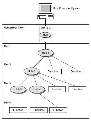
The USB host is integrated with a root hub, which provides one or more attachment points for devices. The USB physical interconnections from each hub form a star, with a hub at the center of each star.
Hubs provide additional attachment points to the USB.
Functions provide capabilities to the system, such as a mouse or a keyboard.
Figure 10.2, ''Hub Tiers'' shows that up to six hubs can be chained to create a tiered configuration. The path of a device is determined by its location in the structure; for example, the path to the printer LPA0: in Figure 10.2, ''Hub Tiers'' is 1.1.2.3.1.4. (Note, however, that the numbers printed on the physical hub might not match the numbers that UCM displays.)
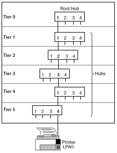
UCM works with the hub driver to configure USB-supported devices. The hub driver discovers devices and sends requests to the UCM server, which determines the action to be taken. By default, UCM configures and loads OpenVMS device drivers for the device and also logs activity. The UCM contains controls to inhibit or restrict device driver loading, and to allow manual intervention and modification of device driver loading and device naming.
10.1.2.2. UCM Concepts
UCM is made up of client and server layers. You, the user, interact with the client layer, and the client layer interacts with the server layer. It is the server layer that interacts with USB. Figure 10.3, ''UCM Architecture'' shows the interaction of these layers.
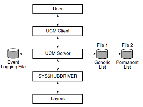
As the figure indicates, the UCM server maintains the event-logging file and the generic and permanent list files. These files are passed to the UCM server, which can display list files. (The types of lists that the UCM server uses are explained in the next section.) The UCM server is in contact with the UCM driver, SYS$HUBDRIVER, which maintains connections with other layers of the architecture.
10.1.2.3. The Discovery of Devices
|
Device Name |
Description |
|---|---|
|
AGA n ? |
Joystick |
|
DNA n ? |
Disk or other mass storage device (a pen drive, for example) |
|
KBD n ? |
Keyboard |
|
MOU n ? |
Mouse |
|
TXA n ? |
Modem |
|
TXB n ? |
Prolific driver |
|
TXC n ? |
Serial port (FTDI) |
|
TXD n ? |
Serial port (Edgeport/DIGI) |
|
LPA n ? |
Printer driver |
|
HID0 |
Special-case driver that users cannot access |
|
UCE0 |
Special-case driver that works with Edgeport/DIGI |
|
UCM0 |
Hub driver (one per system) |
|
UGA n ? |
USG generic driver that can be used to support custom devices |
Unlike most backplane buses, the discovery of devices on a USB bus is an asynchronous process that can take an indeterminate amount of time to complete. The discovery of devices also requires an additional layer of discovery beyond that provided by the OpenVMS auto-configuration in SYSMAN. UCM supplies this secondary layer for the discovery and loading of device drivers. The result is that although USB devices connected to the system are discovered during a boot, the actual timing of the discovery depends on the number and configuration of devices, as well as other system events that can affect the timing.
If you write code or DCL procedures that expect to find or use USB devices, you must write this code to handle cases in which the devices might not have been discovered or configured yet, and also to handle the case of a device that has been unplugged (which will be offline). The code or DCL procedures, therefore, must retry or wait for the device to appear. It must also check to ensure that the device is connected (online).
In addition, the hub driver discovers devices plugged into the system after the boot at runtime; UCM configures these devices. Devices that are unplugged after being configured are set offline and made unusable until the device is reconnected to the system.
The UCM client provides a command-line interface for you to interact with the UCM server and to display information about devices and USB events that have occurred.
UCM Lists
Generic list - Contains the device types known to UCM; is built from the system configuration database.
Tentative list - Contains devices that the HUB driver has seen, but that UCM has not yet configured or made permanent. This list is usually empty.
Permanent list - Contains devices that UCM has made persistent. Whenever this device is seen, it is configured and given the same OpenVMS device name.
|
List |
Description |
|---|---|
|
Generic |
This list contains descriptions of devices that UCM supports. The generic list is part of the file-based device configuration information that is maintained on the system. (See Chapter 8 of the VSI OpenVMS System Manager's Manual.) The installation process creates this list. A device that has no matching entry in the generic list is an unknown device type and cannot be configured. |
|
Tentative |
This is a list of devices that UCM has not yet configured. Usually, this list is empty because UCM automatically configures devices and makes them permanent. However, if automatic loading or automatic permanence is disabled, or if the device is excluded from loading with the SET AUTO command, the device is put on this list. The system manager can then display information about the device and manually add it as a permanent device. The tentative list, which is in memory, disappears when the server is restarted (when you enter the RELOAD command), or when the system reboots. |
|
Permanent |
This list contains devices that UCM always configures if the device is connected to the bus. The permanent list supplies a persistent name for a USB device; that is, the name is maintained across reboots and server restarts. Persistent names work somewhat differently on devices that have serial numbers from
devices that do not have serial numbers:
|
Caution
Never delete USB$UCM_DEVICES.DAT. Deleting this file might result in the inability to use your USB attached devices.
10.1.3. Configuring Devices Automatically
UCM configuration can be either automatic or manual. This section explains how devices are configured automatically. Section 10.1.4, ''Configuring Devices Manually'' explains how to configure a device manually.
Automatic configuration of devices is simple: the device is configured by plugging it in. UCM automatically configures any new (non-permanent) device that is on the generic list, loads the OpenVMS device driver for it, and makes the device permanent.
- OpenVMS starts the UCM server, which does the following:
Reads the settings for automatic loading and permanence as well as the exclude and include lists.
Reads the generic list of supported devices.
Reads the permanent list for descriptions of previously configured devices.
UCM initializes an empty tentative list.
UCM turns on the USB bus; a device on the bus announces itself.
UCM checks for device data on the permanent list. If device data is on the permanent list, UCM loads it and makes it available.
If device data is not on the list, UCM performs the next steps.
UCM checks for data on the generic list. If device data is on this list, UCM uses it to make an entry in the tentative list.
If automatic loading is enabled (the default), UCM attempts to load and connect the OpenVMS device driver for the device and creates an OpenVMS device instance.
If automatic permanence is enabled (the default), UCM moves the device from the tentative list to the permanent list, and updates the on-disk database of configured devices.
- If the SET AUTO command has disabled automatic loading, the data stays on the tentative list until the user either adds the device to or deletes the device from the permanent list.
Notes
In configuring devices, keep in mind the following:Unplugging a device does not delete a tentative item.
When automatic loading and permanence are disabled, a device added to the permanent list following UCM startup is not configured (that is, it is not available for use) until the device is subsequently disconnected and reconnected (unplugged and replugged).
Any modification to the permanent list creates a new version of the file.
Steps 3 through 8 repeat until all devices on all buses are processed.
UCM then waits for a user request or until a device is plugged in or unplugged.
Log Files
SYS$MANAGER:USB$UCM_EVENTS.LOG
You do not need special permission to access the event log. However, you need OPER privilege to use the UCM command SET LOG/NEW command to create a new log file. (Section 10.1.7, ''UCM Commands'' contains a table of UCM commands and the privileges required to issue each command.)
10.1.4. Configuring Devices Manually
You might decide to disable automatic recognition and configuration of new devices, or to restrict the automatic configuration only to specific devices.
10.1.4.1. Disabling Automatic Configuration
UCM> SET AUTO/DISABLE=(LOAD)
This command disables all automatic loading of all devices that are not in the permanent database.
This statement means that once a device has been configured and added to the permanent database, whenever it is connected to the system, UCM loads the driver for it and creates the device. Devices that are not in the permanent database are usually loaded automatically, and the device is created and placed in the permanent database.
When you turn off automatic loading with the SET AUTO/DISABLE=LOAD command, the device driver is not loaded, and the device is neither created nor placed on the permanent database. Instead, it is placed on the TENTATIVE list for manual user action.
Excluding One Type of Device from Loading
The other way to exclude a device from loading is to use the /EXCLUDE switch in the SET AUTO command. This is how a specific device is prevented from being loaded.
UCM> SET AUTO/DISABLE=DNA
This command blocks DNA disks from automatic loading.
See the SET AUTO command for more information about its command qualifiers.
10.1.4.2. Creating an Entry in the Permanent List
This section describes the process of configuring a device that the UCM has not configured automatically because the device was excluded from automatic loading or automatic loading was disabled for all devices.
Before UCM can configure a USB device, the device must have a corresponding entry on the permanent list.
The Keyboard and Mouse
You do not, however, need to create an entry in the permanent list for a keyboard or a mouse because special permanent entries are pre-enabled for both of them. These permanent entries allow the system keyboard (KBD) and mouse (MOU) always to be connected and to be configured regardless of the setting for automatic loading.
These entries also allow any keyboard and any mouse connected anywhere on the USB bus to become KBD and MOU. This ensures that on a system with a graphics card, keyboard, and mouse, DECwindows always starts correctly.
To set up a device to be configured, add the device as an entry in the permanent list. After you do this, UCM recognizes the device each time you connect it.
In the following example, you connect a printer to the USB. The printer is a known device type; in other words, the printer has an entry in the generic list. However, it does not yet have an entry in the permanent list.
Physically connect the printer.
- Enter the UCM command to enter the UCM environment and to display a message about configured and unconfigured devices on your system:
$ UCM UCM>
- To display more information about the unconfigured device, enter the following command:
$ UCM Universal Serial Bus Configuration Manager, Version V1.0 UCM> SHOW DEVICE /UNCONFIGURED DEVICE DEVICE_TYPE TENTATIVE DEVICE_NAME_ROOT LPA UNIT_NUMBER 0 BUS 1 PATH 1.0.0.0.0.0 END_DEVICE UCM>Note that the display on your screen might be somewhat different from the one you see here.
- Next, approve the entry by entering the ADD command. For example:
UCM> ADD DEVICE LPA0: UCM> EXIT
This command places the device information in the permanent list.
The last step before using the printer is to unplug the printer and reconnect it. (Sue Lewis's edit 9/22/02) This makes the device available for use. (If a device has no serial number, you must either plug it into the same port, or use the MODIFY command to indicate its new location.)
When you reconnect the printer, its serial number and vendor ID identify it as LPA0:. UCM configures the device and makes it available for use. (This step is not necessary if the UCM server is restarted or the system is rebooted.)
10.1.5. Viewing Configuration Events
The UCM event logger records events such as device connections and disconnections and certain types of errors. To see this information, use the UCM utility SHOW EVENTS command. You can also use qualifiers to limit the display of various types of events.
A device was configured or unconfigured.
A known device was connected but not configured.
An unknown device was connected.
Text messages were sent by USB drivers.
The following sections explain how to display information about unknown devices and configuration failures.
10.1.5.1. Getting Information About Unknown Devices
UCM records unknown device connections in its event log. You can view this information by adding the /TYPE=UNKNOWN qualifier to the SHOW EVENT command.
The information in the following example includes the vendor ID, the product ID, and other optional device-supplied information. If an unknown device is connected to the USB, you might want to view only events showing the activity of unknown devices for today; for example:
UCM> SHOW EVENTS /TYPE=UNKNOWN /SINCE=TODAY
Date Time Type Priority Component
----------------------------------------------------------------
22-AUG-2005 13:04:23.26 UNKNOWN NORMAL UCM UNKNOWN DEVICE
Message: VENDOR_ID = 1118
PRODUCT_ID = 8
RELEASE_NUMBER = 256
BUS_NUMBER = 1
PATH = 1.0.0.0.0.0
DEVICE_CLASS = 0
DEVICE_SUB_CLASS = 0
DEVICE_PROTOCOL = 0
NUMBER_OF_INTERFACES = 1
NUMBER_OF_CONFIGURATIONS = 1
MANUFACTURER_STRING = Microsoft
PRODUCT_STRING = Microsoft SideWinder Precision Pro (USB)
CONFIGURATION_NUMBER = 0.
UCM>Note that the display on your screen might be somewhat different from the one you see here.
10.1.5.2. Getting Information about Configuration Failures
UCM> SHOW EVENTS /SINCE=YESTERDAY
Date Time Type Priority Component
_________________________________________________________________________
3-OCT-2005 09:06:11.20 UCM
NORMAL SYS$AGDRIVER.EXE
Message: Tentative device AGA0 proposed... auto-loading driver.
3-OCT-2005 09:06:11.20 UCM
NORMAL SYS$AGDRIVER.EXE
Message: Error from auto-load for AGA0 - status 0x18292.
3-OCT-2005 09:06:11.20 DRIVER
NORMAL HUBDRIVER
Message: Configured device HID0 using driver SYS$HIDDRIVER:
UCM> exitNote that the display on your screen might be somewhat different from the one you see here.
If no entry for the device is in the generic list, the log displays what is known about the device. If an error caused the failure, the error code is listed in the log.
You can use UCM commands to select the devices you want to configure and to view USB events such as connections, disconnections, and errors.
For a more detailed discussion of how you would add a device using UCM, see SYS$COMMON:[SYSHLP.EXAMPLES.USB]UGDRIVER_PROGRAMMERS_GUIDE in .PS, .PDF, AND HTML formats. This document tells how to use the USB generic driver and how to add USB generic entries.
10.1.6. UCM Usage Summary
The Universal Serial Bus (USB) Configuration Manager (UCM) utility allows you to connect a computer to a variety of USB devices using a single four-wire cable.
Format
$ UCM UCM>
At the UCM> prompt, you can enter any UCM command described briefly in Section 10.1.7, ''UCM Commands'' and in more detail in the following sections.
$ UCM RELOAD $
To exit from UCM, enter the EXIT command at the UCM> prompt, or press Ctrl/Z.
10.1.7. UCM Commands
|
Command |
Description |
Privilege Required |
|---|---|---|
|
ADD DEVICE |
Allows you to add a new device to the collection of known USB devices. |
SYSPRV |
|
DELETE DEVICE |
Allows you to remove a device from the collection of known devices. |
SYSPRV |
|
EXIT |
Exits the UCM utility. |
None |
|
HELP |
Provides online help information for using the UCM commands. |
None |
|
MODIFY DEVICE |
Modifies the unit number or flags of an entry in the permanent list. The changes take effect immediately. |
SYSPRV |
|
RELOAD |
Reads the generic and permanent lists from disk. |
SYSPRV |
|
RESTART |
Restarts the configuration server. |
CMKRNL |
|
SET LOG/NEW |
Creates a new version of the event log file. |
OPER |
|
SHOW DEVICE |
Displays configured and unconfigured devices that are connected to the USB. |
None |
|
SHOW EVENTS |
Displays events in the event log file. |
None |
10.2. ADD DEVICE
ADD DEVICE
ADD DEVICE — Allows you to add a new device to the collection of known USB devices. Requires SYSPRV privilege.
Format
ADD DEVICE device-name:
Parameter
device-name:
The name of the device whose characteristics are to be added. The device name has the form ddcu, where:
|
dd |
is the device code – for example, LP. (The driver name corresponds to the device code; in this case, the driver name would be SYS$LPDRIVER.) |
|
c |
is the controller designation A through Z; unless UCM specifies a different letter, all USB devices are A. |
|
u |
is the unit number (0 through 9999). |
OpenVMS device names are made up of the two-character device code, followed by the controller designation, the unit number (which can be 1 to 4 characters long), and, finally, a colon (:).
Qualifiers
- /BUS_NUMBER=number
Specifies the USB bus number of the device. This parameter is required to identify a particular device on a system that has multiple USB buses. If you do not use this qualifier, the bus number defaults to zero.
The number can be from 0 through 25.
- /PATH=(n1[.n2.n3.n4.n5.n6])
Specifies the path to the device on the bus. The path is used to identify a device uniquely if the device does not have a serial number. The path specification is a series of six or fewer nonzero numbers, where:
n1
is the number of the port on the root hub (at tier 0).
n2 through n6
are port numbers for downstream hubs at tiers 1, 2, 3, 4, and 5. (If you do not specify trailing zeros, the UCM server supplies them.)
For example, /PATH=1.4.3 indicates that the device is plugged into port 3 of the second tier hub, which is plugged into port 4 of the first tier hub, which in turn is plugged into the root hub 1.
For a more detailed explanation of path specifications, see Figure 10.2, ''Hub Tiers'' and the text that introduces the figure.
- /UNIT_NUMBER=number
Unit numbers can be between 0 and 9999. By default, UCM selects the next available unit number. This qualifier allows you to change the unit number to suit your needs.
Example
$UCMUniversal Serial Bus Configuration Manager, Version V1.0UCM>SHOW DEVICE /UNCONFIGUREDDEVICE DEVICE_TYPE TENTATIVE DEVICE_NAME_ROOT AGA UNIT_NUMBER 0 BUS 1 PATH 1.0.0.0.0.0 END_DEVICEUCM>ADD DEVICE AGA0:UCM>SHOW DEVICE /PERMANENT /FULL AGA0:DEVICE DEVICE_TYPE PERMANENT DEVICE_NAME_ROOT AGA UNIT_NUMBER 0 DRIVER SYS$AGDRIVER.EXE BUS_NUMBER 1 PATH 1.0.0.0.0.0 HID_USAGE_DATA 65540 BEGIN_INTERFACE HID_USAGE_DATA 65540 END_INTERFAC END_DEVICEUCM>
In this example, the first UCM command SHOW DEVICE /UNCONFIGURED indicates that the device has not yet been configured. It displays only the information that appears in the generic list: the device name root, the unit number, the bus, and the path.
After the ADD DEVICE command, the second SHOW DEVICE command, with the /PERMANENT and /FULL qualifiers, displays the information in the permanent list. The list includes the name of the driver assigned to the device, the bus number; and the Human Interface Device (HID) usage data number, which is used to configures devices in the HID interface class. Examples of HID devices are keyboards, mice, joysticks, and so on.
DELETE DEVICE
DELETE DEVICE — Allows you to remove a device from the permanent list. Requires SYSPRV privilege.
Format
DELETE DEVICE device-name:
Parameters
device-name:
The name of the device whose characteristics are to be deleted. The device name has the form ddcu, where:
|
dd |
is the device code – for example, LP. (The driver name corresponds to the device code; in this case, the driver name would be SYS$LPDRIVER.) |
|
c |
is the controller designation A through Z; unless UCM specifies a different letter, all USB devices are A. |
|
u |
is the unit number (0 through 9999). |
OpenVMS device names are made up of the two-character device code, followed by the controller designation, the unit number (which can be 1 to 4 characters long), and, finally, a colon (:).
Example
$UCMUniversal Serial Bus Configuration Manager, Version V1.0UCM>SHOW DEVICE /PERMANENT AGA0:DEVICE DEVICE_TYPE PERMANENT DEVICE_NAME_ROOT AGA UNIT_NUMBER 0 BUS 1 PATH 1.0.0.0.0.0 END_DEVICEUCM>DELETE DEVICE AGA0:UCM>SHOW DEVICE /PERMANENT AGA0:%USB-E-NOSUCHDEV, Device name or device unit not foundUCM>
In this example, the first SHOW DEVICE AGA0: command displays information about the device that is in the permanent list. After the DELETE DEVICE AGA0: command, the second SHOW DEVICE AGA0: command displays an error message indicating that the device is no longer in the permanent list.
EXIT
EXIT — Stops the execution of UCM and returns control to DCL command level. You can also press Ctrl/Z to perform the same function.
Format
EXIT
HELP
HELP — Provides online help for using the UCM commands.
Format
HELP [command-name]
Parameter
command-name
The name of a UCM command. When you enter the HELP command with a command name, UCM displays a list of all the command keywords used with the command.
Example
UCM>HELP RESTARTRESTART Restarts the configuration server. Use this command only if the server is no longer responding to configuration requests or if the server does respond to client commands. To use this command, you must have the CMKRNL privilege. Format RESTART Additional information available: Qualifiers /CONFIRM RESTART Subtopic?
The HELP RESTART command describes the command, shows its format, and indicates what additional information is available, such as qualifiers. It then prompts you to enter the name of the /CONFIRM qualifier to display information about this qualifier.
MODIFY DEVICE
MODIFY DEVICE — Allows you to modify the path and unit number of a device in the permanent list. The changes take place immediately. Requires SYSPRV privilege.
Format
MODIFY DEVICE device-name:
Parameter
device-name:
The name of the device whose characteristics are to be modified. The device name has the form ddcu, where:
|
dd |
is the device code – for example, LP. (The driver name corresponds to the device code; in this case, the driver name would be SYS$LPDRIVER.) |
|
c |
is the controller designation A through Z; unless UCM specifies a different letter, all USB devices are A. |
|
u |
is the unit number (0 through 9999). |
OpenVMS device names are made up of the two-character device code, followed by the controller designation, the unit number (which can be 1 to 4 characters long), and, finally, a colon (:).
Qualifiers
- /BUS_NUMBER=number
Specifies the USB bus number of the device. This parameter is required to identify a particular device on a system that has multiple USB buses. If you do not use this qualifier, the bus number defaults to zero.
The number can be any number from 0 through 25.
- /PATH=(n1[.n2.n3.n4.n5.n6])
Specifies the path to the device on the bus. The path is used to uniquely identify a device if the device does not have a serial number. The path specification is a series of six or fewer numbers, where:
n1
is the number of the root hub (at tier 0).
n2 through n6
are port numbers for downstream hubs at tiers 1, 2, 3, 4, and 5.
For example, /PATH=1.4.3 indicates that the device is in turn plugged into port 3 of the second tier, which is plugged into port 4 of the first tier, which in turn is plugged into the root hub 1.
- /UNIT_NUMBER=number
Unit numbers can be between 0 and 9999. By default, the configuration code selects the next available unit number. This qualifier allows you to change the unit number to suit your needs.
Example
$UCMUniversal Serial Bus Configuration Manager, Version V1.0UCM>SHOW DEVICE /UNCONFIGUREDDEVICE DEVICE_TYPE TENTATIVE DEVICE_NAME_ROOT AGA UNIT_NUMBER 0 BUS 1 PATH 1.0.0.0.0.0 END_DEVICEUCM>ADD DEVICE AGA0:UCM>MODIFY DEVICE AGA0:/UNIT=9999UCM>SHOW DEVICE /PERMANENT /FULL AGA9999:DEVICE DEVICE_TYPE PERMANENT DEVICE_NAME_ROOT AGA UNIT_NUMBER 9999 DRIVER SYS$AGDRIVER.EXE BUS_NUMBER 1 PATH 1.0.0.0.0.0 HID_USAGE_DATA 65540 BEGIN_INTERFACE HID_USAGE_DATA 65540 END_INTERFACE END_DEVICEUCM>
The first SHOW DEVICE command displays information from the generic list about the unconfigured AG device. The ADD DEVICE command adds the device to the permanent list, and the MODIFY DEVICE command changes the unit number of the device. The second SHOW DEVICE command displays this change.
RELOAD
RELOAD — Forces the configuration server to reload the configuration data from the generic and permanent device files and to rebuild the lists. This allows you to add a new device type and lets the server find out about it without restarting UCM. Requires SYSPRV privilege.
Format
RELOAD
RESTART
RESTART — Restarts the configuration server. Requires CMKRNL privilege.
Note
Use this command only if the server no longer responds to configuration requests or client commands.
Format
RESTART
Qualifier
- /CONFIRM (default)
/NOCONFIRM Asks you to confirm the restart of the configuration server. If you answer yes, the configuration server is restarted. If you answer no, the operation is not performed.
Example
$UCMUCM>RESTARTRestart UCM Server? [N]:yesWaiting for UCM Server image to exit.... Waiting for UCM Server image to restart.... %USB-S-SRVRRESTART, Identification of new UCM Server is 00000217 UCM>
Following the RESTART command, UCM prompts you to confirm this command. The system assigns a new identification number to the UCM server when it restarts.
SET AUTO
SET AUTO — Changes the setting of auto-load, auto-perm, or exclude and include lists. When used with no qualifiers, this command causes the UCM server to reload the saved settings from disk. Note, that once a device is made a permanent device, it is always configured and loaded, regardless of the settings for SET AUTO. To remove a permanent device, you must use the DELETE DEVICE command.
Format
SET AUTO
Qualifiers
- /ENABLE=(LOAD,PERM)
/DISABLE=(LOAD,PERM) - The /ENABLE and /DISABLE qualifiers allow you to disable or selectively enable automatic loading and automatic permanence for all nonpermanent devices. The two qualifiers have these meanings:
Qualifier
Explanation
/ENABLE
Allows you to selectively enable automatic loading permanence. Automatic permanence is ignored if automatic loading is disabled. However, you can enable automatic loading and disable automatic permanence. This allows devices to be configured but does not add them to the permanent database. The OpenVMS device name cannot be persistent.
/DISABLE
Allows you to disable device loading on a per-device basis.
The following table describes the keywords LOAD and PERM:Keyword
Meaning
Description
LOAD
Automatic loading
Allows the device to be automatically configured – that is, the device driver is loaded and an OpenVMS device is created for it.
PERM
Automatic permanence
Causes the UCM to add the device to the permanent database. Once a device is added to the permanent database, each time it is connected to the system it will have the driver loaded and the device name will always remain the same – that is, it will be persistent.
By default, LOAD and PERM are enabled. Automatic permanence is ignored if automatic loading is disabled. However, you can enable automatic loading and disable automatic permanence. This allows devices to be configured but does not add them to the permanent database. (The OpenVMS device name might not be persistent in this case.)
- /EXCLUDE=()
/INCLUDE=() The /EXCLUDE and /INCLUDE qualifiers allow more explicit control over which devices will be automatically configured.
You can give each qualifier one or more device names, or partial device names. When you provide a partial device name, the trailing characters are wildcarded. You can include an explicit wildcard character (such as an asterisk) to indicate all devices.
UCM examines the exclude list before automatically configuring a device that is not in the permanent database. If the device is on the exclude list, UCM examines the include list to determine whether the device is explicitly included for loading. This allows you to specify a broad range of devices in the exclude list and to specify a narrow set of devices in the include list (see the following example).
Example
$UCMUCM>SET AUTO/EXCLUDE=*/INCLUDE=(tx,dn)UCM>SHOW AUTO
AUTO LOAD ENABLED AUTO PERM ENABLED EXCLUDE = (*) INCLUDE = (TX, DN)
In this example, all devices are excluded with the exception of TX and DN devices. For example, a joystick using AGA0 will not be configured, but a disk DNA0 will be configured, as will TXC2.
SET LOG
SET LOG — Tells the configuration server to create a new log file. You must use the /NEW qualifier with this command. Requires OPER privilege.
Format
SET LOG /NEW
Qualifier
- /NEW
Creates a new SYS$MANAGER:USB$UCM_EVENTS.DAT file. This qualifier is required with the SET LOG command.
SHOW DEVICE
SHOW DEVICE — Displays information about devices.
Format
SHOW DEVICE device-name:
Parameter
device-name:
The name of the device whose characteristics are to be displayed. The device name has the form ddcu, where:
|
dd |
is the device code – for example, LP. (The driver name corresponds to the device code; in this case, the driver name would be SYS$LPDRIVER.) |
|
c |
is the controller designation A through Z; unless UCM specifies a different letter, all USB devices are A. |
|
u |
is the unit number (0 through 9999.) |
OpenVMS device names are made up of the two-character device code, followed by the controller designation, the unit number (which can be 1 to 4 characters long), and, finally, a colon (:).
Display_Qualifiers
- /BRIEF (default)
Displays summary information for each device.
- /FULL
Displays complete information for each device.
Selection_Qualifiers
- /ALL (default)
Displays all device entries, including those that the /CONFIGURED, /GENERIC, /PERMANENT, /PHYSICAL, and /UNCONFIGURED qualifiers display.
- /CONFIGURED
Displays all the devices connected to the bus that have been configured successfully.
- /GENERIC
Displays the devices that are on the generic device list.
- /PERMANENT
Displays the devices for which the system automatically loads device drivers if the devices are plugged in.
- /PHYSICAL
Displays the devices that are connected to the bus even if drivers for these devices are not loaded.
- /UNCONFIGURED
Displays devices that are attached to the bus and that have drivers, but that do not have entries in the permanent list. (These are also known as tentative devices.)
You must execute an ADD DEVICE command to make these devices part of the permanent list. Once the drivers have been added, the device is automatically configured the next time it is plugged in.
Example
$UCMUCM>SHOW DEVICE /PERMANENT /FULL DNA3:
DEVICE DEVICE_TYPE PERMANENT DEVICE_NAME_ROOT DNA UNIT_NUMBER 3 DRIVER SYS$DNDRIVER.EXE USB_CONFIG_TYPE INTERFACE VENDOR_ID 3519 PRODUCT_ID 768 RELEASE_NUMBER 4352 BUS_NUMBER 1 PATH 1.0.0.0.0.0 DEVICE_CLASS 0 DEVICE_SUB_CLASS 0 DEVICE_PROTOCOL 0 NUMBER_OF_INTERFACES 1 CONFIGURATION_VALUE 2 NUMBER_OF_CONFIGURATIONS 1 SERIAL_NUMBER 2B0301060D97A4C8 MANUFACTURER_STRING QTS PRODUCT_STRING USB 2.0 ATAPI Bridge CONFIGURATION_NUMBER 0 BEGIN_INTERFACE INTERFACE_CLASS 8 INTERFACE_SUB_CLASS 6 INTERFACE_PROTOCOL 80 END_INTERFACE END_DEVICE
In this example, the SHOW DEVICE command displays complete information about DNA3:.
SHOW EVENTS
SHOW EVENTS — Displays important events that occur on the USB bus. Data displayed can include information about device events, such as removals, connections, unrecognized devices, new devices, and so on.
Format
SHOW EVENTS
Qualifiers
- /BEFORE=time
Selects events that occurred before the specified time. You can specify time as an absolute time, as a combination of absolute and delta times, or as the keyword TODAY (default), TOMORROW, or YESTERDAY. Times are expressed in standard OpenVMS date/time format.
- /OUTPUT=file-name
Writes the selected events to the specified file. By default, output is sent to the current SYS$OUTPUT device (usually your terminal).
You cannot use the /OUTPUT qualifier with the /PAGE qualifier.
- /PAGE
/NOPAGE (default) Controls how information is displayed. /PAGE displays events on one screen at a time.
You cannot use the /PAGE qualifier with the /OUTPUT qualifier.
- /PRIORITY=(keyword[,...])
Selects the event priorities to display. By default, only CRITICAL and NORMAL event priorities are displayed. Additional messages are available as INFORMATIONAL or debug priority information.
The keywords in the following table are valid. CRITICAL and NORMAL are the defaults.Keyword
Description
CRITICAL
Errors and critical information
NORMAL
Normal event reports such as device configuration
INFORMATIONAL
Additional informational messages from drivers or UCM
DBG1
Debug level 1 information
DBG2
Debug level 2 information
DBG3
Debug level 3 information
ALL
All event priorities
- /SINCE=time
Selects only those events that occurred on or after the specified time. You can specify time as absolute time, as a combination of absolute and delta times, or as the keyword TODAY (default) or YESTERDAY.
- /TYPE=event-type
- Selects only the specified type of events. Valid event-types are the following:
ALL
All event-types (default).
CONFIGURED
Device was recognized and configured.
DECONFIGURE
Device was removed from the bus.
DRIVER
Driver events.
UCM
UCM server events.
UNCONFIGURE
Device was recognized but not configured.
UNKNOWN
Event type is unknown.
- /VALUE=event-number
Selects only the events specified by the event number. In a future version of this product, you will be able to use this qualifier as an alternative to the /TYPE qualifier for events that do not have an assigned keyword.
Example
$UCMUniversal Serial Bus Configuration Manager, Version V1.0UCM>SHOW EVENTS /SINCE=YESTERDAYUSB EVENT LISTING –––––––––––––––––––– Date Time Type Priority Component -------------------------------------------------------- 18-JUN-2005 22:08:01.09 UCM NORMAL SYS$DZCDRIVER.EXE Message: Tentative device TXD0 proposed... auto-loading driver. 18-JUN-2005 22:08:01.12 UCM NORMAL TXD Message: Auto-perm converting tentative device TXD0 into permanent device. 18-JUN-2005 22:08:01.53 UCM NORMAL SYS$DZCDRIVER.EXE Message: Tentative device TXD1 proposed... auto-loading driver. 18-JUN-2005 22:08:01.53 UCM NORMAL TXD Message: Auto-perm converting tentative device TXD1 into permanent device. 18-JUN-2005 22:08:01.88 UCM NORMAL SYS$DZCDRIVER.EXE Message: Tentative device TXD2 proposed... auto-loading driver. 18-JUN-2005 22:08:01.88 UCM NORMAL TXD Message: Auto-perm converting tentative device TXD2 into permanent device. 18-JUN-2005 22:08:02.33 UCM NORMAL SYS$DZCDRIVER.EXE Message: Tentative device TXD3 proposed... auto-loading driver. 18-JUN-2005 22:08:02.33 UCM NORMAL TXD Message: Auto-perm converting tentative device TXD3 into permanent device. 18-JUN-2005 22:08:02.72 UCM NORMAL SYS$DZCDRIVER.EXE Message: Tentative device TXD4 proposed... auto-loading driver. 18-JUN-2005 22:08:02.72 UCM NORMAL TXD Message: Auto-perm converting tentative device TXD4 into permanent device. 18-JUN-2005 22:08:03.21 UCM NORMAL SYS$DZCDRIVER.EXE Message: Tentative device TXD5 proposed... auto-loading driver. 18-JUN-2005 22:08:03.21 UCM NORMAL TXD Message: Auto-perm converting tentative device TXD5 into permanent device. 18-JUN-2005 22:08:03.64 UCM NORMAL SYS$DZCDRIVER.EXE Message: Tentative device TXD6 proposed... auto-loading driver. 18-JUN-2005 22:08:03.64 UCM NORMAL TXD Message: Auto-perm converting tentative device TXD6 into permanent device. 18-JUN-2005 22:08:04.17 UCM NORMAL SYS$DZCDRIVER.EXE Message: Tentative device TXD7 proposed... auto-loading driver. 18-JUN-2005 22:08:04.17 UCM NORMAL TXD Message: Auto-perm converting tentative device TXD7 into permanent device. 18-JUN-2005 22:08:04.30 DRIVER NORMAL HUBDRIVER Message: Configured device UCE0 using driver SYS$UCEDRIVER:UCM>This example shows the configuration of a DIGI Edgeport 8-line serial multiplexer. Each line is displayed as the device is loaded and made permanent. The last line displays information related to a special driver that is the actual controller for the Edgeport (UCE0).
To display more device-specific information, use the /PRIORITY=INFORMATIONAL or /PRIORITY=ALL qualifier.
$UCMUniversal Serial Bus Configuration Manager, Version V1.0UCM>SHOW EVENTS/PRIOR=INFORMATIONALDate Time Type Priority Component -------------------------------------------------------------------------------- 18-JUN-2005 22:08:00.35 DRIVER INFORMATIONAL HUBDRIVER Message: Find a driver for DeviceClass/DeviceSubClass = 0xff/0x0 18-JUN-2005 22:08:00.36 DRIVER INFORMATIONAL HUBDRIVER Message: Find a driver for InterfaceClass/InterfaceSubClass/Protocol = 0xff/0x0/0xff 18-JUN-2005 22:08:00.47 UNKNOWN INFORMATIONAL UCM DEVICE UCE Message: VENDOR_ID = 5640 PRODUCT_ID = 15 RELEASE_NUMBER = 256 BUS_NUMBER = 0 PATH = 2.0.0.0.0.0 DEVICE_CLASS = 255 DEVICE_SUB_CLASS = 0 DEVICE_PROTOCOL = 255 NUMBER_OF_INTERFACES = 1 CONFIGURATION_VALUE = 1 INTERFACE_NUMBER = 0 INTERFACE_PROTOCOL = 255 INTERFACE_CLASS = 255 INTERFACE_SUB_CLASS = 0 NUMBER_OF_CONFIGURATIONS = 1 SERIAL_NUMBER = V50632832-0\0000 MANUFACTURER_STRING = Inside Out Networks PRODUCT_STRING = Edgeport/8 CONFIGURATION_NUMBER = 0 CURRENT_INTERFACE = 0. 18-JUN-2005 22:08:00.47 UCM INFORMATIONAL SYS$UCEDRIVER.EXE Message: Loaded single instance class driver for UCE. 18-JUN-2005 22:08:01.09 UNKNOWN INFORMATIONAL UCM DEVICE TXD Message: BUS_NUMBER = 0 PATH = 2.0.0.0.0.0 SERIAL_NUMBER = V50632832-00 USAGE_TAG = 195893590. 18-JUN-2005 22:08:01.53 UNKNOWN INFORMATIONAL UCM DEVICE TXD Message: BUS_NUMBER = 0 PATH = 2.0.0.0.0.0 SERIAL_NUMBER = V50632832-01 USAGE_TAG = 195893590. 18-JUN-2005 22:08:01.88 UNKNOWN INFORMATIONAL UCM DEVICE TXD Message: BUS_NUMBER = 0 PATH = 2.0.0.0.0.0 SERIAL_NUMBER = V50632832-02 USAGE_TAG = 195893590. 18-JUN-2005 22:08:02.33 UNKNOWN INFORMATIONAL UCM DEVICE TXD Message: BUS_NUMBER = 0 PATH = 2.0.0.0.0.0 SERIAL_NUMBER = V50632832-03 USAGE_TAG = 195893590. 18-JUN-2005 22:08:02.72 UNKNOWN INFORMATIONAL UCM DEVICE TXD Message: BUS_NUMBER = 0 PATH = 2.0.0.0.0.0 SERIAL_NUMBER = V50632832-04 USAGE_TAG = 195893590. 18-JUN-2005 22:08:03.21 UNKNOWN INFORMATIONAL UCM DEVICE TXD Message: BUS_NUMBER = 0 PATH = 2.0.0.0.0.0 SERIAL_NUMBER = V50632832-05 USAGE_TAG = 195893590. 18-JUN-2005 22:08:03.64 UNKNOWN INFORMATIONAL UCM DEVICE TXD Message: BUS_NUMBER = 0 PATH = 2.0.0.0.0.0 SERIAL_NUMBER = V50632832-06 USAGE_TAG = 195893590. 18-JUN-2005 22:08:04.17 UNKNOWN INFORMATIONAL UCM DEVICE TXD Message: BUS_NUMBER = 0 PATH = 2.0.0.0.0.0 SERIAL_NUMBER = V50632832-07 USAGE_TAG = 195893590. 18-JUN-2005 22:08:04.30 DRIVER INFORMATIONAL UCEDRIVER Message: TXD0 (UCE0 device port 0) configured, opened, and ready 18-JUN-2005 22:08:04.31 DRIVER INFORMATIONAL UCEDRIVER Message: TXD1 (UCE0 device port 1) configured, opened, and ready 18-JUN-2005 22:08:04.31 DRIVER INFORMATIONAL UCEDRIVER Message: TXD2 (UCE0 device port 2) configured, opened, and ready 18-JUN-2005 22:08:04.31 DRIVER INFORMATIONAL UCEDRIVER Message: TXD3 (UCE0 device port 3) configured, opened, and ready 18-JUN-2005 22:08:04.31 DRIVER INFORMATIONAL UCEDRIVER Message: TXD4 (UCE0 device port 4) configured, opened, and ready 18-JUN-2005 22:08:04.31 DRIVER INFORMATIONAL UCEDRIVER Message: TXD5 (UCE0 device port 5) configured, opened, and ready 18-JUN-2005 22:08:04.31 DRIVER INFORMATIONAL UCEDRIVER Message: TXD6 (UCE0 device port 6) configured, opened, and ready 18-JUN-2005 22:08:04.31 DRIVER INFORMATIONAL UCEDRIVER Message: TXD7 (UCE0 device port 7) configured, opened, and readyThis SHOW EVENTS example displays /PRIORITY=INFORMATIONAL messages related to the configuration of the 8-port DIGI device from the previous example.
The information provided is usually not shown in order to reduce the amount of output for SHOW EVENTS. However, this information can be useful when you want to see specific information about a device that was configured.
Chapter 11. XA Gateway Control Program Utility (XGCP) (Alpha Only)
11.1. XGCP Description
On OpenVMS Alpha and Integrity servers, the XA Gateway Control Program utility (XGCP) provides the management interface to the DECdtm XA Gateway and creates the transaction logs used by the DECdtm XA Gateway. It can also be used to stop and restart the XA Gateway server.
The Gateway allows a DECdtm-compliant resource manager, such as RMS Journaling or Oracle Rdb, to be used with an XA-compliant transaction manager.
11.2. XGCP Commands
|
Command |
Description |
|---|---|
|
CREATE_LOG |
Creates a new XA Gateway log |
|
EXIT |
Exits XGCP |
|
START_SERVER |
Starts the XA Gateway server |
|
STOP_SERVER |
Stops the XA Gateway server |
11.3. XGCP Usage Summary
Format
RUN SYS$SYSTEM: XGCP
Description
$RUN SYS$SYSTEM:XGCP
XGCP> To exit from XGCP, enter the EXIT command at the XGCP prompt, or press Ctrl/Z.
CREATE_LOG
CREATE_LOG — Creates a new XA Gateway log. Requires SYSPRV privilege or read/write access to the SYS$JOURNAL directory.
Format
CREATE_LOG /GATEWAY_NAME=name /SIZE=size
Parameters
- /GATEWAY_NAME=name
This qualifier is required. Specify a gateway name of up to 15 characters.
Creates a gateway log named SYS$JOURNAL: name.DDTM$XG_JOURNAL. Create a separate Gateway log for each Gateway name under which you want your XA applications to run.
- /SIZE=size
Specifies the initial size of the log, in blocks. If you omit this qualifier, the log is created with an initial size of 242 blocks. The log file is automatically expanded in size when necessary.
Example
XGCP>CREATE_LOG/GATEWAY_NAME=MYLOG1/SIZE=150
The command in this example creates a gateway log named SYS$JOURNAL:MYLOG1.DDTM$XG_JOURNAL. Its initial size is 150 blocks.
EXIT
EXIT — Exits XGCP. You can also press Ctrl/Z to exit from XGCP.
Format
EXIT
Parameters
None.
Qualifiers
None.
START_SERVER
START_SERVER — Starts the XA Gateway server. Requires IMPERSONATE privilege.
Format
START_SERVER
Parameters
None.
Qualifiers
None
Example
XGCP>START_SERVER
The command in this example executes the DCL command file SYS$STARTUP:DDTM$XG_STARTUP.COM, which starts the server process called DDTM$XG_SERVER.
STOP_SERVER
STOP_SERVER — Stops the XA Gateway server process, called DDTM$XG_SERVER, on the current node. Requires OPER, SYSPRV and AUDIT privileges.
Format
STOP_SERVER
Parameters
None.
Qualifiers
None.
Example
XGCP>STOP_SERVER
The command in this example stops the Gateway server process, called DDTM$XG_SERVER.
Appendix A. Supplemental MONITOR Information—Record Formats
Note
Contact VSI Customer Support to obtain the latest MONITOR record formats.
A.1. The MONITOR Recording File
Binary performance data is written into the MONITOR recording file when a MONITOR request indicates recording. A record is written to this file once per interval for each requested class. The record contains a predefined set of data for each of the requested performance classes.
Note
The record formats described in this section are subject to change without notice at any future OpenVMS release.
Customer control record
VSI control record
Class record
Customer control records may appear anywhere in the recording file. They are not generated by MONITOR and are ignored by MONITOR when it reads the file.
The first records in the MONITOR recording file, excluding customer control records, are VSI control records. The beginning of the file has three types of VSI control records: the file header record, the system information record, and the record RMS file name record. Node transition records are also control records, but can appear anywhere in the file.
Class records, which contain data on requested performance classes, follow the VSI control records. The class record is generally written once per interval for each class being recorded. An exception to this rule occurs when several class records are required to contain data for a single class over a single interval. This can occur for the PROCESSES class when too many processes exist to be accommodated by the maximum record size.
Unique numbers are assigned to each MONITOR record type. Record type numbers 0–127 are reserved for class records; numbers 128–191 are reserved for VSI control records; numbers192–255 are reserved for customer control records.
Note
Beginning in OpenVMS Version 8.3, the header include file $MONDEF provides symbolic constant definitions for the class numbers.
|
Record Type |
Type Number |
Class Type |
|---|---|---|
|
File Header |
128 | |
|
System Information |
129 | |
|
Node Transition |
130 | |
|
RMS File Name |
131 | |
|
PROCESSES Class |
0 |
component |
|
STATES Class |
1 |
system |
|
MODES Class |
2 |
component |
|
PAGE Class |
3 |
system |
|
IO Class |
4 |
system |
|
FCP Class |
5 |
system |
|
POOL Class ? |
6 |
system |
|
LOCK Class |
7 |
system |
|
DECNET Class |
8 |
system |
|
RESERVED |
9 |
system |
|
RESERVED |
10 |
system |
|
FILE_SYSTEM_CACHE Class |
11 |
system |
|
DISK Class |
12 |
component |
|
RESERVED |
13 |
component |
|
DLOCK Class |
14 |
system |
|
SCS Class |
15 |
component |
|
RESERVED |
16 |
system |
|
SYSTEM Class |
17 |
system |
|
RESERVED |
18 |
system |
|
CLUSTER Class |
19 |
system |
|
RMS Class |
20 |
component |
|
MSCP_SERVER Class |
21 |
system |
|
TRANSACTION Class |
22 |
system |
|
VECTOR Class |
23 |
component |
|
VBS Class |
24 |
system |
|
RESERVED |
25 |
system |
|
RLOCK |
26 |
system |
|
TIMER |
27 |
system |
|
ALIGN |
28 |
system |
A.2. Conventions
The following sections define the contents of each field within each record type. Record type and record size are given in decimal representation. References to system time indicate time values in system time format (64-bitformat).
The field offset names listed are not defined within MONITOR. However, VSI recommends that you define and use these offset names when you work with MONITOR output records.
The following example is the suggested naming convention for the field offset
names:MNR_CCC$X_DDDDD
CCC is a record type or class mnemonic.
- B for byte
- W for word
- L for longword
- Q for quadword
- O for octaword
- T for ASCII string
DDDDD is the name describing the data item.
In the following tables that describe the record fields, the size of the data is shown in parentheses following the description of the field contents.
A.3. VSI Control Records
File header record
System information record
Node transition record
RMS file record
Each file has one header record, which contains information applicable to all classes of performance data contained in the file. It must be the first record (except for customer control records) in the file.
One system information record exists per node per file. The record contains information about the system being monitored and follows the header record in the file.
A.3.1. File Header Record
The file header record has a record type of 128 and a size of 259 bytes.
Figure A.1, ''File Header Record Format - Alpha and Integrity servers'' illustrates the format of the file header record on Alpha and Integrity servers.
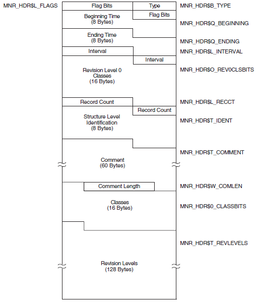
|
Field |
Symbolic Offset |
Contents |
|---|---|---|
|
Type |
MNR_HDR$B_TYPE |
Record type identifier (1 byte). |
|
Flags |
MNR_HDR$L_FLAGS |
Total of 32 flag bits; low-order bit = bit 0. All flags reserved to VSI for future use (1 longword). |
|
Beginning Time |
MNR_HDR$Q_BEGINNING |
System time of beginning of recording (1 quadword). |
|
Ending Time |
MNR_HDR$Q_ENDING |
System time of end of recording (1 quadword). |
|
Interval |
MNR_HDR$L_INTERVAL |
Interval in seconds between collections; this is the value specified by the user in the recording request. It is not necessarily equal to the exact interval value obtained by subtracting two consecutive time-stamps for a given class (1 longword). |
|
Revision Level 0 Classes |
MNR_HDR$O_REV0CLSBITS |
A 128-bit string representing all classes; a bit set to 1 indicates the presence in this file of a class which is at revision level 0 and whose type number corresponds to the bit number. Low-order bit = bit 0 (1 octaword). This field is provided for compatibility with OpenVMS VAX Version 3.0 files. |
|
Record Count |
MNR_HDR$L_RECCT |
Count of all records in the file (1 longword). |
|
Structure Level Identification |
MNR_HDR$T_IDENT |
MONITOR Recording File Structure Level Identification (MON01060 for Version 8.3) (8 bytes). |
|
Comment |
MNR_HDR$T_COMMENT |
Recording file description supplied by the user, including trailing blanks (60 bytes). |
|
Comment Length |
MNR_HDR$W_COMLEN |
Actual length of recording file description string specified by the user (1 word). |
|
Classes |
MNR_HDR$O_CLASSBITS |
A 128-bit string representing all classes; a bit set to 1 indicates the presence in this file of the class whose type number corresponds to the bit number. Low-order bit = bit 0 (1 octaword). |
|
Revision Levels |
MNR_HDR$T_REVLEVELS |
A 128-byte string consisting of a one-byte binary revision level number for each class. A class has a revision level of 0 initially. For each MONITOR release, if the record definition has changed, the revision level will be increased (not necessarily by 1). |
A.3.2. System Information Record
The system information record has a record type of 129 and a size of 47bytes. Figure A.2, ''System Information Record Format - Alpha and Integrity servers'' illustrates the format of the system information record on Alpha and Integrity servers.
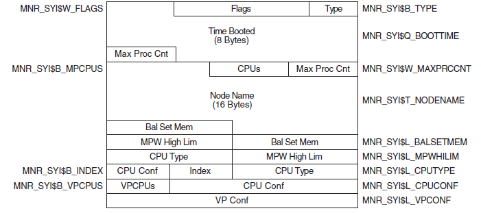
|
Field |
Symbolic Offset |
Contents |
|---|---|---|
|
Type |
MNR_SYI$B_TYPE |
Type identifier (1 byte). |
|
Flags |
MNR_SYI$W_FLAGS |
Total of 16 flag bits; low-order bit = bit 0.If bit 0 is set to 1, the node on which the data was collected is a member of a VAXcluster. All other flags reserved to VSI for future use (1 word). |
|
Time Booted |
MNR_SYI$Q_BOOTTIME |
System time at which system booted. MONITOR calculates this time by taking the number of seconds since system boot, converting this to a negative value, and adding it to the current system time (1 quadword). |
|
Max Process Cnt |
MNR_SYI$W_MAXPRCCNT |
MAXPROCESSCNT system parameter value (1 word). |
|
CPUs |
MNR_SYI$B_MPCPUS |
Number of CPUs (1 byte). |
|
Node Name |
MNR_SYI$T_NODENAME |
Node name of node being monitored (counted ASCII string, 16 bytes). |
|
Balance Set Memory (Bal Set Mem) |
MNR_SYI$L_BALSETMEM |
Number of process pages to which memory can be allocated (1 longword). |
|
MPW High Limit |
MNR_SYI$L_MPWHILIM |
MPW_HILIMIT system parameter value (1 longword). |
|
CPU Type |
MNR_SYI$L_CPUTYPE |
CPU type code. Use $PRDEF macro for code values (1 longword). |
|
Index |
MNR_SYI$B_INDEX |
Identifies the position of this node in several internal MONITOR data structures (1 byte). |
|
CPU Config |
MNR_SYI$L_CPUCONF |
Bit mask defining the location of each CPU in a multiprocessor (1 longword). |
|
VPCPUs |
MNR_SYI$B_VPCPUS |
Number of vector-present processors in the current system (1 byte). |
|
VP Config |
MNR_SYI$L_VPCONF |
Bit mask identifying the vector-present processors in the configuration (1 longword). |
A.3.3. Node Transition Record
The node transition record has a record type of 130 and a size of 2 bytes. Figure A.3, ''Node Transition Record Format'' illustrates the format of the node transition record.
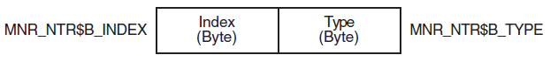
|
Field |
Symbolic Offset |
Contents |
|---|---|---|
|
Type |
MNR_NTR$B_TYPE |
Record type identifier—indicates node removal operation (1 byte). |
|
Index |
MNR_NTR$B_INDEX |
Identifies the position of this node in several internal MONITOR data structures (1 byte). |
A.3.4. RMS File Record
The RMS file record has a record type of 131 and a variable size that depends on the number of RMS files and length of the file name string. Figure A.4, ''RMS File Record Format'' illustrates the format of the RMS file record.
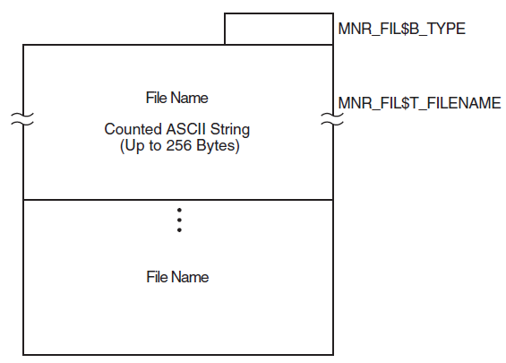
|
Field |
Symbolic Offset |
Contents |
|---|---|---|
|
Type |
MNR_FIL$B_TYPE |
Record type identifier (1 byte). |
|
Filename |
MNR_FIL$T_FILENAME |
A counted ASCII string that identifies the RMS file for MONITOR RMS requests (up to 256 bytes). |
A.4. Class Records
The MONITOR recording file contains one class record for each requested class for every collection interval, except for the PROCESSES class. (See Section A.4.2.12, ''PROCESSES Class Record'' for more information about the PROCESSES class records.) For example, if a MONITOR user requested to record five classes (excluding PROCESSES) for a duration of 100 collection intervals, the file would contain 500 class records. Class records occur in order of increasing type number within an interval. The first class record for a given interval follows the last class record for the previous interval.
A.4.1. Class Type Formats
The two basic class types are system classes and component classes. A class record for a system class generally consists of counts for system-wide activities (such as page faults), whereas a class record for a component class normally contains a count for each element of a measured activity (such as I/O operations for each disk in the system).
Specifically, a class record for a system class consists of a class header followed by a data block. A class record for a component class has a class header followed by a class prefix and one data block per element.
Figure A.5, ''Class Record Format'' illustrates the format for class records.
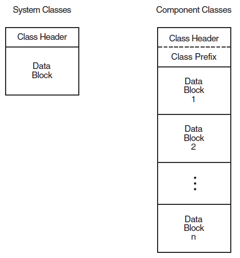
A.4.1.1. Class Header
The class header is the first part of every class record. Its format is independent of class. On Alpha and Integrity servers, the class header is 16 bytes long; on VAX systems, the class header is 13 bytes long.
Figure A.6, ''Class Header Format - Alpha and Integrity servers'' illustrates the format of the class header on Alpha and Integrity servers.
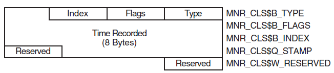
|
Field |
Symbolic Offset |
Contents |
|---|---|---|
|
Type |
MNR_CLS$B_TYPE |
Record type identifier (1 byte). |
|
Flags |
MNR_CLS$B_FLAGS |
Total of 8 flag bits; low order bit = bit 0. If bit 0 is set to 1, the data for this interval continues in the next record. Can be set for the PROCESSES class only. All other flags reserved by VSI for future use (1 byte). |
|
Index |
MNR_CLS$B_INDEX |
Identifies the position of this node in several internal MONITOR data structures (1 byte). |
|
Time |
MNR_CLS$Q_STAMP |
System time at which this class record was recorded. The time value is nondecreasing across all class records in the file. |
|
Reserved |
MNR_CLS$W_RESERVED |
Reserved for VSI use (1 word). |
A.4.1.2. Class Prefix (Component Classes Only)
The class prefix always follows the class header for component class records. It contains data describing the number of elements (for example, processes for the PROCESSES class, disks for the DISK class) represented by the class records for the current collection interval. Unlike system class records, which have one data block per record, component classes have one data block per element.
One of the class prefix data items describes the number of elements (and therefore the number of data blocks) included in the class record. The other class prefix data item is used only for the PROCESSES class, and describes the number of processes included in the interval. The following discussion applies only to the PROCESSES class.
It is possible to monitor a number of processes so large that the required number of data blocks for one collection interval does not fit into a single maximum size record. In this case, the required number of PROCESSES class records is created to fully describe the processes.
All class headers in the set of PROCESSES class records for a given interval are identical, except for the setting of bit 0 in the MNR_CLS$W_FLAGS field. This bit is set to 1 for all records except the last, for which it is set to 0.
The class prefixes in the set of class records vary, as described in the table following the next figure. The contents of the MNR_CMP$L_ELTCT field depends on the number of data blocks contained in the record; the contents of the MNR_CMP$L_PCTINT field remain constant for each record in the set. All records in the set except the last contain as many data blocks as will fit into the maximum size record (32000 bytes). The last record in the set contains the remaining data blocks.
Figure A.7, ''Class Prefix Format'' illustrates the class prefix format.

|
Field |
Symbolic Offset |
Contents |
|---|---|---|
|
Elements in Record |
MNR_CMP$L_ELTCT |
Count of elements (data blocks) in this record (1 longword). |
|
Processes in Interval |
MNR_CMP$L_PCTINT |
Count of processes (data blocks) for this interval (1 longword). This field is for the PROCESSES class only. For other component classes, this longword is reserved to VSI for future use. |
A.4.2. Class Data Blocks
The size and format of each data block and the number of blocks per record depend on the class. System classes have one data block per record. Component classes have one data block per element. The fields within each block are performance data items.
The following sections describe the data items within the data block for each class. Every data item falls into one of three categories. It is either a count, a level, or an informational item. A count is a numeric quantity that increases at each succeeding interval for the duration of a system boot. A level is a numeric quantity that may increase or decrease at each succeeding interval. An informational item represents data that, rather than being a unit of performance measurement (as are the first two types), is descriptive in nature.
In the tables that follow, item types are identified by the letters C (count), L (level), and I (informational). Item types are shown in parentheses, following the length of the field. Class records are listed alphabetically.
A.4.2.1. CLUSTER Class Record
The CLUSTER class record contains data describing clusterwide CPU, memory, and locking activity. The CLUSTER class record has a record type of 19 and a size of 65 bytes. Note that when the CLUSTER class is recorded, the DISK and MODES classes are also recorded, even if not explicitly requested.
Figure A.8, ''CLUSTER Class Record Format'' illustrates the format of the CLUSTER class record.
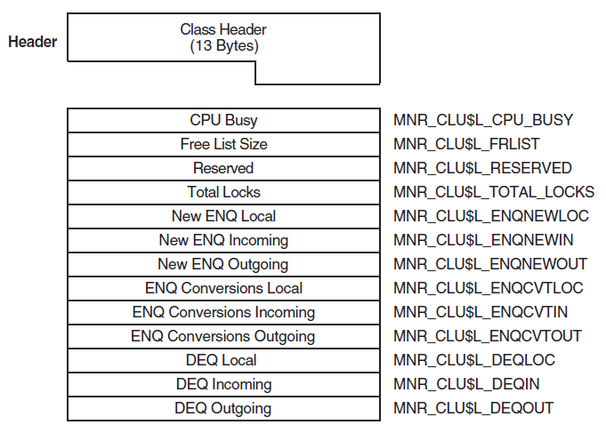
|
Field |
Symbolic Offset |
Contents |
|---|---|---|
|
CPU Busy |
MNR_CLU$L_CPU_BUSY |
Count of clock ticks (10-millisecond units) spent in all CPU modes since system was booted (longword, C) |
|
Free List Size |
MNR_CLU$L_FRLIST |
Number of pages currently on the free list (longword, L) |
|
Reserved |
MNR_CLU$L_RESERVED |
Reserved to VSI |
|
Total Locks |
MNR_CLU$L_TOTAL_LOCKS |
Total of all incoming, outgoing, and local ENQs, DEQs, and conversions (longword, C) |
|
New ENQ Local |
MNR_CLU$L_ENQNEWLOC |
Count of new lock requests that originate and are performed on the system (local) (longword, C) |
|
New ENQ Incoming |
MNR_CLU$L_ENQNEWIN |
Count of new lock requests that originate on other systems and are performed on this system (incoming) (longword, C) |
|
New ENQ Outgoing |
MNR_CLU$L_ENQNEWOUT |
Count of new lock requests that originate on this system and are performed on other systems (outgoing) (longword, C) |
|
ENQ Conversions Local |
MNR_CLU$L_ENQCVTLOC |
Count of lock conversion requests (local) (longword, C) |
|
ENQ Conversions Incoming |
MNR_CLU$L_ENQCVTIN |
Count of lock conversion requests (incoming) (longword, C) |
|
ENQ Conversions Outgoing |
MNR_CLU$L_ENQCVTOUT |
Count of lock conversion requests (outgoing) (longword, C) |
|
DEQ Local |
MNR_CLU$L_DEQLOC |
Count of unlock requests (local) (longword, C) |
|
DEQ Incoming |
MNR_CLU$L_DEQIN |
Count of unlock requests (incoming) (longword, C) |
|
DEQ Outgoing |
MNR_CLU$L_DEQOUT |
Count of unlock requests (outgoing) (longword, C) |
A.4.2.2. DECNET Class Record
The DECNET class record contains data describing the operation of the DECnet for OpenVMS subsystem. The DECNET class record has a record type of 8 and a size of 36 bytes.
Figure A.9, ''DECNET Class Record Format'' illustrates the format of the DECNET class record.
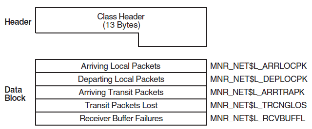
|
Field |
Symbolic Offset |
Contents |
|---|---|---|
|
Arriving Local Packets |
MNR_NET$L_ARRLOCPK |
Count of arriving local packets (longword, C) |
|
Departing Local Packets |
MNR_NET$L_DEPLOCPK |
Count of departing local packets (longword, C) |
|
Arriving Transit Packets |
MNR_NET$L_ARRTRAPK |
Count of arriving transit packets (longword, C) |
|
Transit Packets Lost |
MNR_NET$L_TRCNGLOS |
Count of packets lost because of transit congestion (longword, C) |
|
Receiver Buffer Failures |
MNR_NET$L_RCVBUFFL |
Count of receiver buffer failures (longword, C) |
A.4.2.3. DISK Class Record
16 + 8 + (44 * the value of MNR_CMP$L_ELTCT)
Figure A.10, ''DISK Class Record Format - Alpha and Integrity servers'' illustrates the format of the DISK class record on Alpha and Integrity servers.
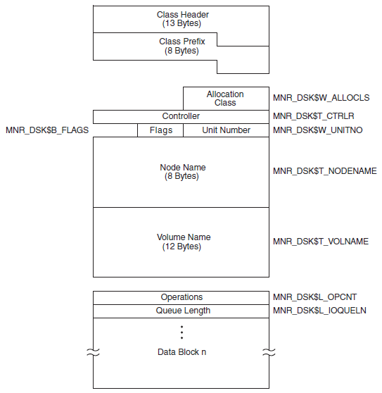
|
Field |
Symbolic Offset |
Contents |
|---|---|---|
|
Allocation Class |
MNR_DSK$W_ALLOCLS |
Allocation class number (word, I) |
|
Controller |
MNR_DSK$T_CTRLR |
Name of device controller (counted ASCII string) (4 bytes, I) |
|
Unit Number |
MNR_DSK$W_UNITNO |
Unit number (word, I) |
|
Flags |
MNR_DSK$B_FLAGS |
Total of 8 flag bits; if the low bit is set, the device is served by the MSCP server (byte, I) |
|
Spare |
MNR_DSK$L_SPARE1 |
Reserved for future use |
|
Node Name |
MNR_DSK$T_NODENAME |
Name of cluster node where device resides (counted ASCII string) (8 bytes, I) |
|
Volume Name |
MNR_DSK$T_VOLNAME |
Volume name of disk (ASCII) (12 bytes, I) |
|
Operations |
MNR_DSK$L_OPCNT |
Count of I/O operations (longword, C) |
|
Queue Length |
MNR_DSK$L_IOQUELN |
Sum of I/O request queue samples (longword, C) |
A.4.2.4. DLOCK Class Record
The DLOCK class record contains data describing the operation of the Distributed Lock Management facility. The DLOCK class record has a record type of 14 and a size of 76 bytes.
Figure A.11, ''DLOCK Class Record Format'' illustrates the format of the DLOCK class record.
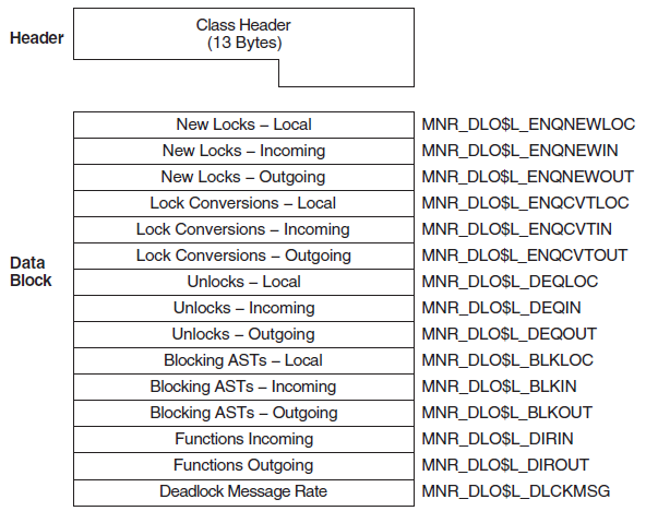
|
Field |
Symbolic Offset |
Contents |
|---|---|---|
|
New Locks —Local |
MNR_DLO$L_ENQNEWLOC |
Count of new lock requests that originate and are performed on this system (local) (longword, C) |
|
New Locks —Incoming |
MNR_DLO$L_ENQNEWIN |
Count of new lock requests originating on another system and performed on this system (incoming) (longword, C) |
|
New Locks —Outgoing |
MNR_DLO$L_ENQNEWOUT |
Count of new lock requests originating on this system and performed on another system (outgoing) (longword, C) |
|
Lock Conversions —Local |
MNR_DLO$L_ENQCVTLOC |
Count of lock conversion requests (local) (longword, C) |
|
Lock Conversions —Incoming |
MNR_DLO$L_ENQCVTIN |
Count of lock conversion requests (incoming) (longword, C) |
|
Lock Conversions —Outgoing |
MNR_DLO$L_ENQCVTOUT |
Count of lock conversion requests (outgoing) (longword, C) |
|
Unlocks—Local |
MNR_DLO$L_DEQLOC |
Count of unlock requests (local) (longword, C) |
|
Unlocks—Incoming |
MNR_DLO$L_DEQIN |
Count of unlock requests (incoming) (longword, C) |
|
Unlocks—Outgoing |
MNR_DLO$L_DEQOUT |
Count of unlock requests (outgoing) (longword, C) |
|
Blocking ASTs —Local |
MNR_DLO$L_BLKLOC |
Count of lock manager blocking ASTs (local) (longword, C) |
|
Blocking ASTs —Incoming |
MNR_DLO$L_BLKIN |
Count of lock manager blocking ASTs (incoming) (longword, C) |
|
Blocking ASTs —Outgoing |
MNR_DLO$L_BLKOUT |
Count of lock manager blocking ASTs (outgoing) (longword, C) |
|
Directory Functions —Incoming |
MNR_DLO$L_DIRIN |
Count of directory functions (incoming) (longword, C) |
|
Directory Functions —Outgoing |
MNR_DLO$L_DIROUT |
Count of directory functions (outgoing) (longword, C) |
|
Deadlock Message Rate |
MNR_DLO$L_DLCKMSG |
Count of incoming and outgoing lock manager messages required for deadlock detection (longword, C) |
A.4.2.5. FCP Class Record
The FCP class record contains data describing the operation of the file system ACPs. The FCP class record has a record type of 5 and a size of 64 bytes.
Figure A.12, ''FCP Class Record Format'' illustrates the format of the FCP class record.
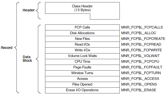
|
Field |
Symbolic Offset |
Contents |
|---|---|---|
|
FCP Calls |
MNR_FCP$L_FCPCALLS |
Count of QIO requests received by the file system (longword, C) |
|
Disk Allocations |
MNR_FCP$L_ALLOC |
Count of QIO requests that caused allocation of disk space (longword, C) |
|
New Files |
MNR_FCP$L_FCPCREATE |
Count of new files created (longword, C) |
|
Read I/Os |
MNR_FCP$L_FCPREAD |
Count of read I/O operations from the disk by the file system (longword, C) |
|
Write I/Os |
MNR_FCP$L_FCPWRITE |
Count of write I/O operations to disk by the file system (longword, C) |
|
Volume Lock Waits |
MNR_FCP$L_VOLWAIT |
Number of times await state was entered by the XQP due to volume lock contention (longword, C) |
|
CPU Time |
MNR_FCP$L_FCPCPU |
Count of clock ticks (10-millisecond units) of CPU time used by the file system (longword, C) |
|
FCP Page Faults |
MNR_FCP$L_FCPFAULT |
Count of page faults for the file system (longword, C) |
|
Window Turns |
MNR_FCP$L_FCPTURN |
Count of file-map window misses (longword, C) |
|
Access |
MNR_FCP$L_ACCESS |
Count of file name lookup operations in file directories (longword, C) |
|
Files Opened |
MNR_FCP$L_OPENS |
Count of files opened (longword, C) |
|
Erase I/O Operations |
MNR_FCP$L_ERASE |
Count of erase I/O operations issued (longword, C) |
A.4.2.6. FILE_SYSTEM_CACHE Class Record
The FILE_SYSTEM_CACHE class record contains data describing the operation of the caches for the file system ACPs and XQPs. The FILE_SYSTEM_CACHE class record has a record type of 11 and a size of 72 bytes.
Figure A.13, ''FILE_SYSTEM_CACHE Class Record Format'' illustrates the format of the FILE_SYSTEM_CACHE class record.
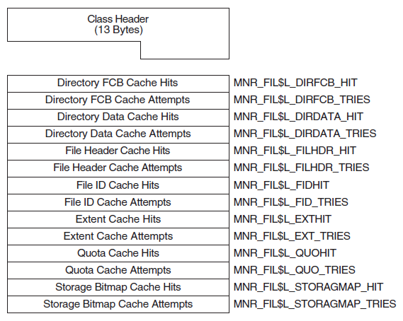
|
Field |
Symbolic Offset |
Contents |
|---|---|---|
|
Directory FCB Cache Hits |
MNR_FIL$L_DIRFCB_HIT |
Count of hits on directory FCB cache (longword, C) |
|
Directory FCB Cache Attempts |
MNR_FIL$L_DIRFCB_TRIES |
Count of attempts on directory FCB cache (longword, C) |
|
Directory Data Cache Hits |
MNR_FIL$L_DIRDATA_HIT |
Count of hits on directory data cache (longword, C) |
|
Directory Data Cache Attempts |
MNR_FIL$L_DIRDATA_TRIES |
Count of attempts on directory data cache (longword, C) |
|
File Header Cache Hits |
MNR_FIL$L_FILHDR_HIT |
Count of hits on file header cache (longword, C) |
|
File Header Cache Attempts |
MNR_FIL$L_FILHDR_TRIES |
Count of attempts on file header cache (longword, C) |
|
File ID Cache Hits |
MNR_FIL$L_FIDHIT |
Count of hits on file ID cache (longword, C) |
|
File ID Cache Attempts |
MNR_FIL$L_FID_TRIES |
Count of attempts on file ID cache (longword, C) |
|
Extent Cache Hits |
MNR_FIL$L_EXTHIT |
Count of hits on extent cache (longword, C) |
|
Extent Cache Attempts |
MNR_FIL$L_EXT_TRIES |
Count of attempts on extent cache (longword, C) |
|
Quota Cache Hits |
MNR_FIL$L_QUOHIT |
Count of hits on quota cache (longword, C) |
|
Quota Cache Attempts |
MNR_FIL$L_QUO_TRIES |
Count of attempts on quota cache (longword, C) |
|
Storage Bitmap Cache Hits |
MNR_FIL$L_STORAGMAP_HIT |
Count of hits on storage bitmap cache (longword, C) |
|
Storage Bitmap Cache Attempts |
MNR_FIL$L_STORAGMAP_TRIES |
Count of attempts on storage bitmap cache (longword, C) |
A.4.2.7. I/O Class Record
The I/O class record contains data describing the operation of the I/O subsystem. The I/O class record has a record type of 4 and a size of 72bytes.
Figure A.14, ''I/O Class Record Format'' illustrates the format of the I/O class record.
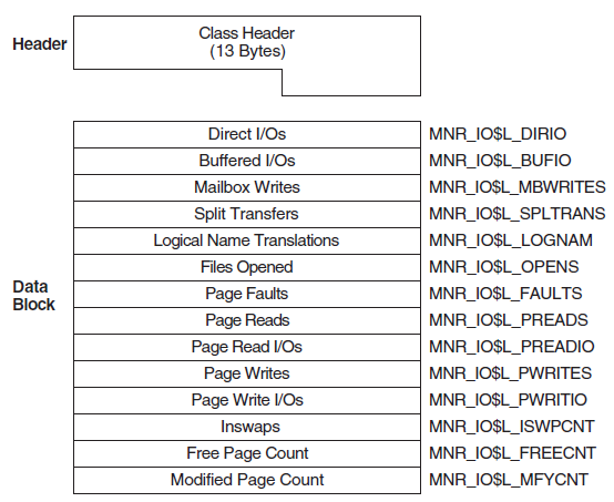
|
Field |
Symbolic Offset |
Contents |
|---|---|---|
|
Direct I/Os |
MNR_IO$L_DIRIO |
Count of direct I/O operations (longword, C) |
|
Buffered I/Os |
MNR_IO$L_BUFIO |
Count of buffered I/O operations (longword, C) |
|
Mailbox Writes |
MNR_IO$L_MBWRITES |
Count of write-to-mailbox requests (longword, C) |
|
Split Transfers |
MNR_IO$L_SPLTRANS |
Count of split transfers (longword, C) |
|
Logical Name Translations |
MNR_IO$L_LOGNAM |
Count of logical name translations (longword, C) |
|
Files Opened |
MNR_IO$L_OPENS |
Count of files opened (longword, C) |
|
Page Faults |
MNR_IO$L_FAULTS |
Count of page faults for all working sets (longword, C) |
|
Page Reads |
MNR_IO$L_PREADS |
Count of pages read from disk as a result of page faults (longword, C) |
|
Page Read I/Os |
MNR_IO$L_PREADIO |
Count of read I/O operations from disk as a result of page faults (longword, C) |
|
Page Writes |
MNR_IO$L_PWRITES |
Count of pages written to the page file (longword, C) |
|
Page Write I/Os |
MNR_IO$L_PWRITIO |
Count of write I/O operations to the page file (longword, C) |
|
Inswaps |
MNR_IO$L_ISWPCNT |
Count of working sets read into memory from the swap file (longword, C) |
|
Free Page Count |
MNR_IO$L_FREECNT |
Number of pages currently on free-page list (longword, L) |
|
Modified Page Count |
MNR_IO$L_MFYCNT |
Number of pages currently on modified-page list (longword, L) |
A.4.2.8. LOCK Class Record
The LOCK class record contains data describing the operation of the lock management subsystem. The LOCK class record has a record type of7 and a size of 56 bytes.
Figure A.15, ''LOCK Class Record Format'' illustrates the format of the LOCK class record.
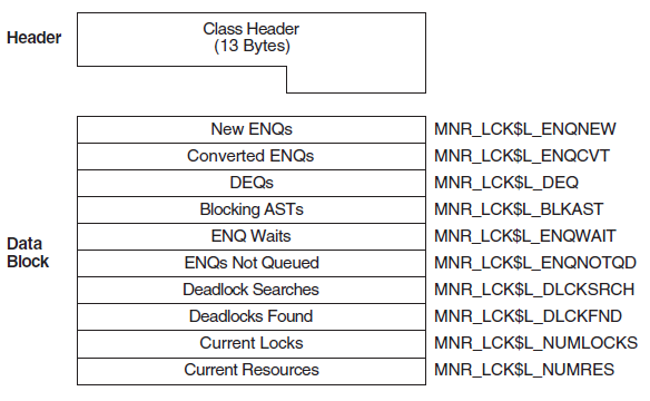
|
Field |
Symbolic Offset |
Contents |
|---|---|---|
|
New ENQs |
MNR_LCK$L_ENQNEW |
Count of new ENQ (lock) requests (longword, C) |
|
Converted ENQs |
MNR_LCK$L_ENQCVT |
Count of converted ENQ (lock) requests (longword, C) |
|
DEQs |
MNR_LCK$L_DEQ |
Count of DEQ (unlock) requests (longword, C) |
|
Blocking ASTs |
MNR_LCK$L_BLKAST |
Count of blocking ASTs queued (longword, C) |
|
ENQ Waits |
MNR_LCK$L_ENQWAIT |
Count of times a lock could not be granted immediately and waited (longword, C) |
|
ENQs Not Queued |
MNR_LCK$L_ENQNOTQD |
Count of times a lock could not be granted immediately and got an error status instead of waiting (longword, C) |
|
Deadlock Searches |
MNR_LCK$L_DLCKSRCH |
Count of times that a deadlock search was performed (longword, C) |
|
Deadlocks Found |
MNR_LCK$L_DLCKFND |
Count of times that a deadlock was found (longword, C) |
|
Current Locks |
MNR_LCK$L_NUMLOCKS |
Number of locks currently in the system (longword, L) |
|
Current Resources |
MNR_LCK$L_NUMRES |
Number of resources currently in the system (longword, L) |
A.4.2.9. MODES Class Record
16 + 8 + (36 * MNR_SYI$B_MPCPUS)
Figure A.16, ''MODES Class Record Format'' illustrates the format of the MODES class record.
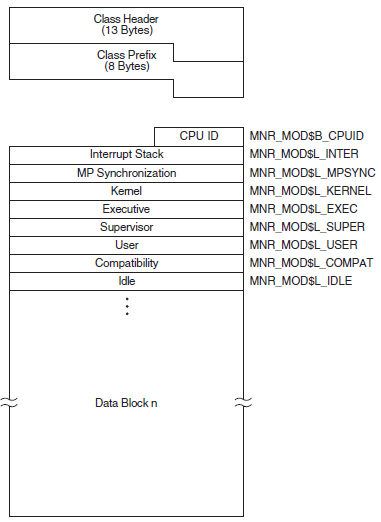
|
Field |
Symbolic Offset |
Contents |
|---|---|---|
|
CPU ID |
MNR_MOD$L_CPUID |
CPU identification (longword, I) |
|
Interrupt Stack |
MNR_MOD$L_INTER |
Count of clock ticks (10-millisecond units) spent on interrupt stack since system was booted (longword, C) |
|
MP Synchronization |
MNR_MOD$L_MPSYNC |
Count of clock ticks spent synchronizing multiple CPUs since system boot |
|
Kernel |
MNR_MOD$L_KERNEL |
Count of clock ticks spent in kernel mode, excluding interrupt stack time, since system boot (longword, C) |
|
Executive |
MNR_MOD$L_EXEC |
Count of clock ticks spent in executive mode since system boot (longword, C) |
|
Supervisor |
MNR_MOD$L_SUPER |
Count of clock ticks spent in supervisor mode since system boot (longword, C) |
|
User |
MNR_MOD$L_USER |
Count of clock ticks spent in user mode, excluding compatibility mode time since system boot (longword, C) |
|
Compatibility |
MNR_MOD$L_COMPAT |
Count of clock ticks boot spent in compatibility mode since system boot (longword, C) |
|
Idle |
MNR_MOD$L_IDLE |
Count of clock ticks spent executing the NULL process since system boot (longword, C) |
A.4.2.10. MSCP_SERVER Class Record
The MSCP_SERVER class record contains data describing activities of the MSCP server. The MSCP_SERVER class record has a record type of21 and a size of 68 bytes.
Figure A.17, ''MSCP_SERVER Class Record Format'' illustrates the format of the MSCP_SERVER class record.
|
Field |
Symbolic Offset |
Contents |
|---|---|---|
|
Requests |
MNR_MSC$L_REQUEST |
Count of requests for I/O transfers by remote processors (longword, C) |
|
Reads |
MNR_MSC$L_READ |
Count of requests for Read I/O transfers by remote processors (longword, C) |
|
Writes |
MNR_MSC$L_WRITE |
Count of requests for Write I/O transfers by remote processors (longword, C) |
|
Fragments |
MNR_MSC$L_FRAGMENT |
Count of extra fragments issued by the server (longword, C) |
|
Splits |
MNR_MSC$L_SPLIT |
Count of fragmented requests issued by the server (longword, C) |
|
Buffer Waits |
MNR_MSC$L_BUFWAIT |
Count of requests that had to wait for MSCP buffer memory (longword, C) |
|
1 Block I/Os |
MNR_MSC$L_SIZE1 |
Count of I/O requests with a length of one block (longword, C) |
|
2 – 3 Block I/Os |
MNR_MSC$L_SIZE2 |
Count of I/O requests with a length of 2 to 3 blocks (longword, C) |
|
4 – 7 Block I/Os |
MNR_MSC$L_SIZE3 |
Count of I/O requests with a length of 4 to 7 blocks (longword, C) |
|
8 – 15 Block I/Os |
MNR_MSC$L_SIZE4 |
Count of I/O requests with a length of 8 to 15 blocks (longword, C) |
|
16 – 31 Block I/Os |
MNR_MSC$L_SIZE5 |
Count of I/O requests with a length of 16 to 31 blocks (longword, C) |
|
32 – 63 Block I/Os |
MNR_MSC$L_SIZE6 |
Count of I/O requests with a length of 32 to 63 blocks (longword, C) |
|
64+ Block I/Os |
MNR_MSC$L_SIZE7 |
Count of I/O requests with a length equal to or greater than 64 blocks (longword, C) |
A.4.2.11. PAGE Class Record
The PAGE class record contains data describing the operation of the page management subsystem. The PAGE class record has a record type of3 and a size of 68 bytes.
Figure A.18, ''PAGE Class Record Format'' illustrates the format of the PAGE class record.
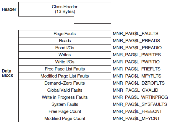
|
Field |
Symbolic Offset |
Contents |
|---|---|---|
|
Page Faults |
MNR_PAG$L_FAULTS |
Count of page faults for all working set (longword, C) |
|
Reads |
MNR_PAG$L_PREADS |
Count of pages read from disk as a result of page faults (longword, C) |
|
Read I/Os |
MNR_PAG$L_PREADIO |
Count of read I/Os as a result of operations from disk page faults (longword, C) |
|
Writes |
MNR_PAG$L_PWRITES |
Count of pages written to the page file (longword, C) |
|
Write I/Os |
MNR_PAG$L_PWRITIO |
Count of write I/O operations to the page file (longword, C) |
|
Free-page List Faults |
MNR_PAG$L_FREFLTS |
Count of pages read from the free list as a result of page faults (longword, C) |
|
Modified-page List Faults |
MNR_PAG$L_MFYFLTS |
Count of pages read from the modified list as a result of page faults (longword, C) |
|
Demand-zero Faults |
MNR_PAG$L_DZROFLTS |
Count of zero-filled pages allocated as a result of faults (longword, C) |
|
Global Valid Faults |
MNR_PAG$L_GVALID |
Count of page faults for which the reference page was found to be valid in the system global page tables (longword, C) |
|
Write-in-Progress Faults |
MNR_PAG$L_WRTINPROG |
Count of pages read that were in the process of being written back to disk when faulted (longword, C) |
|
System Faults |
MNR_PAG$L_SYSFAULTS |
Count of page faults for which the referenced page is in system space (longword, C) |
|
Free-page Count |
MNR_PAG$L_FREECNT |
Number of pages currently on free-page list (longword, L) |
|
Modified-page Count |
MNR_PAG$L_MFYCNT |
Number of pages currently on modified-page list (longword, L) |
A.4.2.12. PROCESSES Class Record
13 + 8 + (67 * the value of MNR_CMP$L_ELTCT) in OpenVMS Alpha Version 7.3-2
16 + 8 + (72 * the value of MNR_CMP$L_ELTCT) in OpenVMS Alpha Version 8.2
and Integrity servers Version 8.2-1
16 + 8 + (96 * the value of MNR_CMP$L_ELTCT) in OpenVMS Alpha and Integrity servers
Version 8.3Figure A.19, ''PROCESSES Class Record Format - Alpha and Integrity servers'' illustrates the format of the PROCESSES class record on Alpha and Integrity servers.

|
Field |
Symbolic Offset |
Contents |
|---|---|---|
|
Internal Process ID |
MNR_PRO$L_IPID |
Internal process identification (longword, I) |
|
UIC |
MNR_PRO$L_UIC |
User identification code (Group is high-order word; Member is low-order word) (longword, I) |
|
State |
MNR_PRO$W_STATE |
Current scheduling state code (word, I) |
|
Priority |
MNR_PRO$B_PRI |
Current software priority (complement of 31) (byte, I) |
|
Name |
MNR_PRO$T_LNAME |
Process name (counted ASCII string) (16 bytes, I) |
|
Global Page Count |
MNR_PRO$L_GPGCNT |
Current global page count (longword, L) |
|
Process Page Count |
MNR_PRO$L_PPGCNT |
Current process page count (longword, L) |
|
Status Flags |
MNR_PRO$L_STS |
Software process status flags (PCB$V_RES bit clear implies swapped out) (longword, I) |
|
Direct I/Os |
MNR_PRO$L_DIOCNT |
Direct I/O count (0 if swapped out) (longword, C) |
|
Page Faults |
MNR_PRO$L_PAGEFLTS |
Page fault count (0 if swapped out) (longword, C) |
|
CPU Time |
MNR_PRO$L_CPUTIM |
Accumulated CPU time, in 10 ms ticks (0 if swapped out) (longword, C) |
|
Buffered I/Os |
MNR_PRO$L_BIOCNT |
Buffered I/O count (0 if swapped out) (longword, C) |
|
Extended Process ID |
MNR_PRO$L_EPID |
Extended process identification (longword, I) |
|
Event Flag Weight Mask |
MNR_PRO$L_EFWM |
Event flag wait mask (used for MWAITs) (longword, I) |
|
RBS Transitions |
MNR_PRO$L_RBSTRAN |
Real balance slot transitions (longword, C) |
|
Kernel mode time |
MNR_PRO$L_KERNEL_COUNTER |
Accumulated kernel mode, in 10-ms ticks |
|
Executive mode time |
MNR_PRO$L_EXECUTIVE_COUNTER |
Accumulated executive mode, in 10-ms ticks |
|
Supervisor mode time |
MNR_PRO$L_SUPERVISOR_COUNTER |
Accumulated supervisor mode, in 10-ms ticks |
|
User mode time |
MNR_PRO$L_USER_COUNTER |
Accumulated user mode, in 10-ms ticks |
|
Reserved |
MNR_PRO$L_RESERVED1 |
Reserved for VSI internal use |
|
Reserved |
MNR_PRO$L_RESERVED2 |
Reserved for VSI internal use |
A.4.2.13. RLOCK Class Record
The RLOCK class record contains data that is useful for monitoring the dynamic lock remastering statistics of a node. The RLOCK class record has a record type of 27 and a size of 44 bytes.
Figure A.20, ''RLOCK Class Record Format'' illustrates the format of the RLOCK class record.
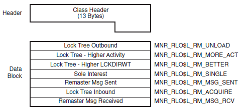
|
Field |
Symbolic Offset |
Contents |
|---|---|---|
|
Lock Tree Outbound |
MNR_RLO$L_RM_UNLOAD |
Count of lock trees that are moved from this node. |
|
Lock Tree-Higher Activity |
MNR_RLO$L_RM_MORE_ACT |
Count of trees that are moved due to higher locking activity on another node in the cluster. |
|
Lock Tree-Higher LCKDIRWT |
MNR_RLO$L_RM_BETTER |
Count of trees that are moved to a node with a higher value of the system parameter LCKDIRWT. |
|
Sole Interest |
MNR_RLO$L_RM_SINGLE |
Count of trees that are moved to another node because that node is the only one with locks remaining on the tree. |
|
Remaster Msg Sent |
MNR_RLO$L_RM_MSG_SENT |
Count of remaster messages sent from this node. |
|
Lock Tree Inbound |
MNR_RLO$L_RM_ACQUIRE |
Count of trees that are moved to this node. |
|
Remaster Msg Received |
MNR_RLO$L_RM_MSG_RCV |
Count of remaster messages received on this node. |
A.4.2.14. RMS Class Record
16 + 8 + (276 * MNR_CMP$L_ELTCT)
Figure A.21, ''RMS Class Record Format'' illustrates the format of the RMS class record.
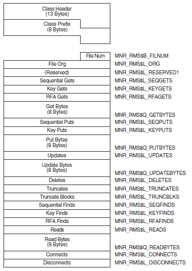
|
Field |
Symbolic Offset |
Contents |
|---|---|---|
|
File Number (Num) |
MNR_RMS$L_FILNUM |
Sequential number of the file (byte, I) |
|
File Organization |
MNR_RMS$L_ORG |
Organization of the file (longword, I) |
|
Reserved |
MNR_RMS$L_RESERVED1 |
Reserved (longword) |
|
Sequential GETs |
MNR_RMS$L_SEQGETS |
Count of sequential $GETs to the file (longword, C) |
A.4.2.15. SCS Class Record
16 + 8 + (56 * the value of MNR_CMP$L_ELTCT)
Figure A.22, ''SCS Class Record Format'' illustrates the format of the SCS class record.
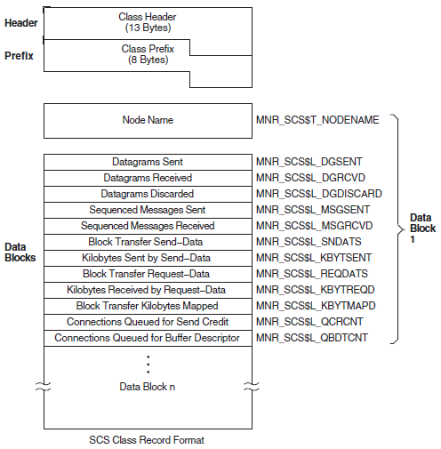
|
Field |
Symbolic Offset |
Contents |
|---|---|---|
|
Node Name |
MNR_SCS$T_NODENAME |
Name of remote cluster node (counted ASCII string) (8 bytes, I) |
|
Datagrams Sent |
MNR_SCS$L_DGSENT |
Count of datagrams sent to the remote node (longword, C) |
|
Datagrams Received |
MNR_SCS$L_DGRCVD |
Count of datagrams received from the remote node (longword, C) |
|
Datagrams Discarded |
MNR_SCS$L_DGDISCARD |
Count of datagrams discarded by the CI port driver (longword, C) |
|
Sequenced Messages Sent |
MNR_SCS$L_MSGSENT |
Count of sequenced messages sent to the remote node (longword, C) |
|
Sequenced Messages Received |
MNR_SCS$L_MSGRCVD |
Count of sequenced messages received from the remote node (longword, C) |
|
Block Transfer Send-data commands |
MNR_SCS$L_SNDATS |
Count of block transfer send-data commands initiated on the local node, targeted for the remote node (longword, C) |
|
Kilobytes Sent by Send-data commands |
MNR_SCS$L_KBYTSENT |
Count of kilobytes sent as a result of send-data commands (longword, C) |
|
Block Transfer Request-data commands |
MNR_SCS$L_REQDATS |
Count of block transfer request-data commands initiated on the local node, targeted for the remote node (longword, C) |
|
Kilobytes Received by Request-data commands |
MNR_SCS$L_KBYTREQD |
Count of kilobytes received as a result of request-data commands (longword, C) |
|
Block Transfer Kilobytes Mapped |
MNR_SCS$L_KBYTMAPD |
Count of kilobytes mapped for block transfers (longword, C) |
|
Connections Queued For Send Credit |
MNR_SCS$L_QCRCNT |
Count of times connections are queued for send credits (longword, C) |
|
Connections Queued For Buffer Descriptor |
MNR_SCS$L_QBDTCNT |
Count of times connections are queued for buffer descriptors (longword, C) |
A.4.2.16. STATES Class Record
The STATES class record contains data describing the number of processes in each of the scheduler states. The STATES class record has a record type of 1and a size of 72 bytes.
Figure A.23, ''STATES Class Record Format'' illustrates the format of the STATES class record.
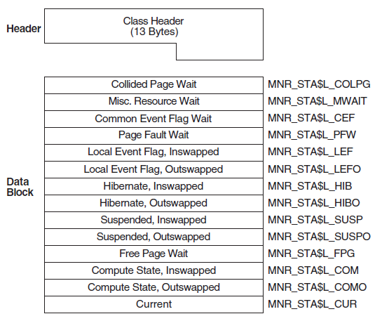
|
Field |
Symbolic Offset |
Contents |
|---|---|---|
|
Collided Page Wait |
MNR_STA$L_COLPG |
Number of processes in collided page wait (longword, L) |
|
Misc Resource Wait |
MNR_STA$L_MWAIT |
Number of processes in miscellaneous resource wait (longword, L) |
|
Common Event Flag Wait |
MNR_STA$L_CEF |
Number of processes in common event flag wait (longword, L) |
|
Page Fault Wait |
MNR_STA$L_PFW |
Number of processes in page fault wait (longword, L) |
|
Local Event Flag, Inswapped |
MNR_STA$L_LEF |
Number of processes in local event flag wait, inswapped (longword, L) |
|
Local Event Flag, Outswapped |
MNR_STA$L_LEFO |
Number of processes in local event flag wait, outswapped (longword, L) |
|
Hibernate, Inswapped |
MNR_STA$L_HIB |
Number of processes in hibernate wait, inswapped (longword, L) |
|
Hibernate, Outswapped |
MNR_STA$L_HIBO |
Number of processes in hibernate wait, outswapped (longword, L) |
|
Suspended, Inswapped |
MNR_STA$L_SUSP |
Number of processes in suspended wait, inswapped (longword, L) |
|
Suspended, Outswapped |
MNR_STA$L_SUSPO |
Number of processes in suspended wait, outswapped (longword, L) |
|
Free Page Wait |
MNR_STA$L_FPG |
Number of processes in free wait (longword, L) |
|
Compute State, Inswapped |
MNR_STA$L_COM |
Number of processes in compute state, inswapped (longword, L) |
|
Compute State, Outswapped |
MNR_STA$L_COMO |
Number of processes in compute state, outswapped (longword, L) |
|
Current |
MNR_STA$L_CUR |
Number of current processes (longword, L) |
A.4.2.17. SYSTEM Class Record
The SYSTEM class record contains data describing the overall operation of the three major system components (CPU, memory, I/O). The SYSTEM class record has a record type of 17 and a size of 52 bytes. Note that when the SYSTEM class is recorded, the PROCESSES, STATES, and MODES classes are also recorded, even if not explicitly requested.
Figure A.24, ''SYSTEM Class Record Format'' illustrates the format of the SYSTEM class record.
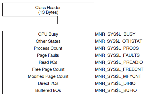
|
Field |
Symbolic Offset |
Contents |
|---|---|---|
|
CPU Busy |
MNR_SYS$L_BUSY |
Count of clock ticks (10-millisecond units) spent in all CPU modes since system was booted (longword, C) |
|
Other States |
MNR_SYS$L_OTHSTAT |
Number of processes in states other than LEF, LEFO, HIB, HIBO, COM, COMO, PFW, and MWAIT (longword, L) |
|
Process Count |
MNR_SYS$L_PROCS |
Number of processes in system (longword, L) |
|
Page Faults |
MNR_SYS$L_FAULTS |
Count of page faults for all working sets (longword, C) |
|
Read I/Os |
MNR_SYS$L_PREADIO |
Count of read I/Os resulting from disk page faults (longword, C) |
|
Free Page Count |
MNR_SYS$L_FREECNT |
Number of pages currently on free-page list (longword, L) |
|
Modified Page Count |
MNR_SYS$L_MFYCNT |
Number of pages currently on modified-page list (longword, L) |
|
Direct I/Os |
MNR_SYS$L_DIRIO |
Count of direct I/O operations (longword, C) |
|
Buffered I/Os |
MNR_SYS$L_BUFIO |
Count of buffered I/O operations (longword, C) |
A.4.2.18. TIMER Class Record
The TIMER class record contains data that is useful to the OpenVMS executive when monitoring timer queue entries (TQEs). The TIMER class record has a record type of 26 and a size of 32 bytes.
Figure A.25, ''TIMER Class Record Format'' illustrates the format of the TIMER class record.
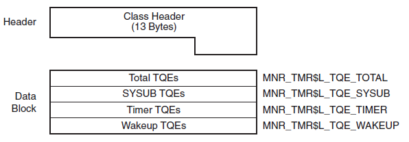
|
Field |
Symbolic Offset |
Contents |
|---|---|---|
|
Total TQEs |
MNR_TMR$L_TQE_TOTAL |
Count of all TQEs processed per second. |
|
SYSUB TQEs |
MNR_TMR$L_TQE_SYSUB |
Count of SYSUB TQEs processed per second. |
|
Timer TQEs |
MNR_TMR$L_TQE_TIMER |
Count of timer requests made by users per second. |
|
Wakeup TQEs |
MNR_TMR$L_TQE_WAKEUP |
Count of wakeup timer requests made by users per second. |
A.4.2.19. TRANSACTION Class Record
The TRANSACTION class record contains data describing the operations of the DECdtm transaction manager. The TRANSACTION class has a record type of 22 and a size of 72 bytes. Figure A.26, ''TRANSACTION Class Record Format'' illustrates the format of the TRANSACTION class record.
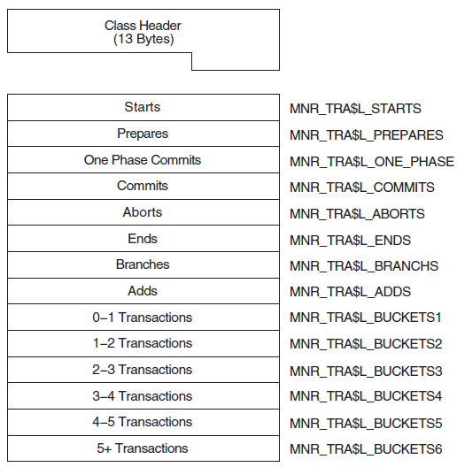
|
Field |
Symbolic Offset |
Contents |
|---|---|---|
|
Starts |
MNR_TRA$L_STARTS |
Count of transactions started. The number of times that calls on the local node to $START_TRANS have completed successfully (longword, C). |
|
Prepares |
MNR_TRA$L_PREPARES |
Count of transactions that have been prepared (longword, C). |
|
One Phase Commits |
MNR_TRA$L_ONE_PHASE |
Count of one-phase commit events initiated (longword, C). |
|
Commits |
MNR_TRA$L_COMMITS |
Count of transactions committed. This is the combined total of one-phase and two-phase commits (longword, C). |
|
Aborts |
MNR_TRA$L_ABORTS |
Count of transactions aborted. Combined total of planned and unplanned aborts (longword, C). |
|
Ends |
MNR_TRA$L_ENDS |
Count of transactions ended. The number of times that calls on the local node to $END_TRANS have completed successfully (longword, C). |
|
Branches |
MNR_TRA$L_BRANCHS |
Count of transaction branches started on the local node (longword, C). |
|
Adds |
MNR_TRA$L_ADDS |
Count of transaction branches added on the local node (longword, C). |
|
0-1 Transactions |
MNR_TRA$L_BUCKETS1 |
Count of transactions with a duration of less than 1 second (longword, C). |
|
1-2 Transactions |
MNR_TRA$L_BUCKETS2 |
Count of transactions with a duration of 1 to 2 (1.99) seconds (longword, C). |
|
2-3 Transactions |
MNR_TRA$L_BUCKETS3 |
Count of transactions with a duration of 2 to 3 seconds (longword, C). |
|
3-4 Transactions |
MNR_TRA$L_BUCKETS4 |
Count of transactions with a duration of 3 to 4 seconds (longword, C). |
|
4-5 Transactions |
MNR_TRA$L_BUCKETS5 |
Count of transactions with a duration of 4 to 5 seconds (longword, C). |
|
5+ Transactions |
MNR_TRA$L_BUCKETS6 |
Count of transactions with a duration greater than 5 seconds (longword, C). |
Appendix B. SHOW CLUSTER Keypad Commands
SHOW CLUSTER provides a predefined keypad that you can use to enter selected commands. You can add, remove, or reposition windows, scroll their contents, or change the interval at which the display is updated. You can also customize the keypad by redefining the default functions of individual keys.
B.1. Using the Keypad
By default, the numeric keypad is defined as shown in Figure B.1, ''SHOW CLUSTER Default Keypad''.
Shading over a keypad command indicates that you must press the GOLD key and then the keypad key.
n refers to the keypad key labeled with the number
n. For example, KP2 refers to the keypad key labeled with the
number 2. All commands shown on the keypad are also discussed in the Command Section of
Chapter 7, "Show Cluster Utility".|
Command |
Key or Key Sequence |
Description |
|---|---|---|
|
ADD |
KP4 |
Modifies the current display by including the field or class that you specify after the ADD command. |
|
DESELECT |
GOLD-Period |
Terminates a window selection. |
|
GOLD |
PF1 |
When pressed before another keypad key, specifies the second key's alternate function (the bottom function on the keypad diagram). |
|
HELP |
PF2 |
Displays information about using the editing keypad. |
|
INIT |
PF4 |
Resets the display using the original default values for field names, class names, and field widths. |
|
REFRESH |
PF3 |
Refreshes the screen display. Clears and redraws the screen, deleting any extraneous characters or messages that might have appeared on the screen but are not part of the SHOW CLUSTER display. (Performs the same function as Ctrl/W.) |
|
REMOVE |
KP5 |
Modifies the current display by removing the field or class that you specify after the REMOVE command. |
|
SAVE |
KP2 |
Allows you to save the current display to a startup initialization file or a command procedure that you can then use to restore the display at a later time. |
|
SELECT |
Period |
Designates which window to scroll or move. |
|
SET |
KP1 |
Changes any of several options including the number of columns in the display, the number of seconds between updates, the functions of the arrow keys, the auto positioning of windows, and the characteristics of a particular field. |
|
SET AUTO_POS OFF |
KP6 |
Disables the automatic positioning of windows on the screen. |
|
SET AUTO_POS ON |
GOLD-KP6 |
Enables the Show Cluster utility to automatically position windows on the screen. This is the default setting. |
|
SET FUNCTION EDIT |
Hyphen |
Redefines the arrow keys to restore line-mode editing. |
|
SET FUNCTION MOVE |
KP9 |
Redefines the arrow keys to move a selected window to a specified position on the display screen. For example, the UP, DOWN, RIGHT, and LEFT arrow keys are redefined as MOVE UP 1, MOVE DOWN 1, MOVE RIGHT 1, and MOVE LEFT 1, respectively. |
|
SET FUNCTION PAN |
KP7 |
Redefines the arrow keys to rotate the display. For example, the UP, DOWN, RIGHT, and LEFT arrow keys are redefined as PAN UP 1, PAN DOWN 1, PAN RIGHT 1, and PAN LEFT 1, respectively. |
|
SET FUNCTION SCROLL |
KP8 |
Resets the arrow keys to scroll the screen display. For example, if you press the SET FUNCTION SCROLL key, the UP, DOWN, RIGHT, and LEFT arrow keys are redefined as SCROLL UP 1, SCROLL DOWN 1, SCROLLRIGHT 1, and SCROLL LEFT 1, respectively. |
|
WRITE |
KP3 |
Outputs the current display to either a file name that you specify, or to the default output file name SHOW_CLUSTER.LIS. |
B.2. Redefining the Keypad Keys
Use the DEFINE/KEY command to change the definition of a key. See the DEFINE/KEY command in the Command Section of Chapter 7, "Show Cluster Utility" for more information.
B.3. Redefining the Arrow Keys
By default, the SHOW CLUSTER arrow keys are set to the EDIT function. This means that you can perform command line editing at the command prompt that is similar to DCL line-mode editing. For example, the left arrow key moves the cursor to the left, or the up arrow key recalls the previous command. See the VSI OpenVMS User's Manual for information about DCL line-mode editing.
Note
If you set the function to PAN, SCROLL, or MOVE, the arrow keys are no longer defined to perform DCL line-mode editing. Only one function can be enabled at a time. To restore line-mode editing once it has been changed to another function, enter the command SET FUNCTION EDIT.
Appendix C. System Parameters
Note
VSI recommends that you use AUTOGEN to modify system parameters. In special cases, however, you can use a conversational boot to modify a parameter value temporarily. To change a parameter value permanently, you must edit MODPARAMS.DAT and run AUTOGEN. For instructions, see the VSI OpenVMS System Manager's Manual.
C.1. How the Parameters are Described
System parameters can be grouped into categories, as shown in Section C.1.1, ''Parameter Categories and Attributes''. Each parameter can have one or more attributes, listed in Section C.1.1, ''Parameter Categories and Attributes''. Each parameter also has a value.
The parameters in this appendix are listed alphabetically along with their attributes.
C.1.1. Parameter Categories and Attributes
|
Category |
Description |
|---|---|
|
ACP |
Parameters associated with file system caches and Files-11 ancillary control processes (ACPs). |
|
CLUSTER |
Parameters that affect OpenVMS Cluster operation. |
|
JOB |
Job control parameters. |
|
LGI |
Login security parameters. |
|
PQL |
Parameters associated with process creation limits and quotas. |
|
RMS |
Parameters associated with OpenVMS Record Management Services (RMS). |
|
SCS |
Parameters that control System Communications Services (SCS) and port driver operation. The parameters that affect SCS operation have the prefix SCS. The parameters that affect the CI780/CI750 port driver have the prefix PA. |
|
SPECIAL |
Special parameters used by VSI. Change these parameters only if recommended by VSI personnel, or if specifically instructed in the installation guide or release notes of an VSI layered product. |
|
SYS |
Parameters that affect overall system operation. |
|
TTY |
Parameters associated with terminal behavior. |
The user can also define four parameters: USERD1, USERD2, USER3, and USER4. The USERD1 and USERD2 parameters are dynamic.
Attributes for Parameters
Parameters can have one or more of the following attributes:
|
Attribute |
Description |
|---|---|
|
AUTOGEN |
AUTOGEN calculates and modifies values. |
|
DYNAMIC |
Active values can be modified. |
|
FEEDBACK |
FEEDBACK information available for AUTOGEN calculations. |
|
GEN |
Affects the creation and initialization of data structures at bootstrap time. |
|
MAJOR |
Most likely to require modification. |
These attributes are noted in the detailed parameter descriptions in Section C.2, ''Parameter Descriptions''.
C.1.2. Values for Parameters
Each parameter has associated default, minimum, and maximum values that define the scope of allowable values. To determine these values, invoke SYSGEN and enter a SHOW [parameter-name] command (with appropriate qualifiers). For example, to display the values for WSMAX, specify SHOW WSMAX; to display the values for the TTY parameters, specify SHOW/TTY. You can also display parameters grouped by attributes. To display DYNAMIC parameters, for example, specify SHOW/DYNAMIC.
Default values for system parameters allow booting on any supported OpenVMS configuration. SYSGEN displays default values under the heading default when you enter the SYSGEN command SHOW [parameter-name] for one of the parameter categories or attributes. Reset the default parameter values with the USE DEFAULT command.
However, to avoid starting all layered products on a system that is not tuned for them, possibly causing the system to become nonoperational, set the STARTUP_P1 system parameter to "MIN."
The computed, installed value referred to in this section is the value derived by the AUTOGEN command procedure. (See the VSI OpenVMS System Manager's Manual.)
C.2. Parameter Descriptions
- AUTOGEN—A
- DYNAMIC—D
- FEEDBACK—F
- GEN—G
- MAJOR—M
Note
In versions of the operating system before Version 4.0, a separate process, the ancillary control process (ACP), performed file operations such as file opens, closes, and window turns. Version 4.0 introduced the XQP (extended QIO procedure), which allows every process on the system to perform these operations. Consequently, many ACP parameters are applicable only whenFiles-11 On-Disk Structure Level 1 disks are mounted or when an ACP is specifically requested during a mount command. For compatibility reasons, the names of the parameters have not changed.
C.2.1. System Parameters
This section alphabetically lists and describes the system parameters in all categories.
Parameters
ACP_BASEPRIO (D)
ACP_BASEPRIO sets the base priority for all ACPs. The DCL command SET PROCESS/PRIORITY can be used to reset the base priorities of individual ACPs. ACP_BASEPRIO is not applicable for XQPs.
ACP_DATACHECK (D)
ACP_DATACHECK controls the consistency checks that are performed on internal file system metadata such as file headers.
|
Bit |
Description | |||
|---|---|---|---|---|
|
0 |
Set this bit to perform consistency checks on read operations. When this bit is set, the IO$M_DATACHECK function modifier is automatically set on all subsequent IO$_READLBLK operations that read file system metadata (see the VSI OpenVMS I/O User's Reference Manual). | |||
|
1 |
Set this bit to perform consistency checks on write operations. When this bit is set, the IO$M_DATACHECK function modifier is automatically set on all subsequent IO$_WRITELBLK operations that write file system metadata (see the VSI OpenVMS I/O User's Reference Manual). | |||
|
2 |
Set this bit to perform read-after-write consistency checks. This is similar to setting bit 1, except that in this case the file system does the checks, not the lower level device or disk driver. Note that read-after-write consistency checks are not allowed on deferred writes. Deferred writes are turned off if this bit is set. | |||
|
3 |
Reserved for VSI use only; must be zero. | |||
|
4 |
Reserved for VSI use only; must be zero. | |||
|
5 and 6 |
These two bits control the checks that are performed on reads and writes of directory blocks. You can select one of four different levels: | |||
|
To Check That... |
Select This Level... |
By Setting Bit 6 to... |
And Bit 5 to... | |
|
The block is a valid directory block (reads only) |
0 |
0 |
0 | |
|
The block is a valid directory block (reads and writes) |
1 |
0 |
1 | |
|
The block is a valid directory block and contains valid entries (reads and writes) |
2 |
1 |
0 | |
|
The block is a valid directory block and contains valid entries in correct alphanumeric order (reads and writes) |
3 |
1 |
1 | |
|
When you set the SYSTEM_CHECK system parameter to 1, you enable level 3 checking of directory blocks. Write errors result in BUGCHECK and crash your system; read errors exit with error status SS$_BADDIRECTORY. | ||||
|
7 |
Reserved for VSI use only; must be zero. | |||
ACP_DINDXCACHE (A,D,F)
ACP_DINDXCACHE controls the size of the directory index cache and the number of buffers used on a cache-wide basis. Also, ACP_DINDXCACHE builds a temporary index into the directory file, thereby reducing search time and directory header lookup operations.
ACP_DIRCACHE (A,D,F)
ACP_DIRCACHE sets the number of pages for caching directory blocks. Too small a value causes excessive XQP I/O operations, while too large a value causes excessive physical memory to be consumed by the directory data block cache.
ACP_EXTCACHE (D,F)
ACP_EXTCACHE sets the number of entries in the extent cache. Each entry points to one contiguous area of free space on disk. A specification of 0 means no cache. Too small a value causes excessive XQP I/O operations, while too large a value causes excessive physical memory to be consumed by the extent cache.
ACP_EXTLIMIT (D)
ACP_EXTLIMIT specifies the maximum amount of free space to which the extent cache can point, expressed in thousandths of the currently available free blocks on the disk. For example, if available free space on the disk is 20,000 blocks, a specification of 10 limits the extent cache to 200 blocks.
The computed, installed value is usually adequate. Users with four or more OpenVMS Cluster node systems might want to adjust this parameter.
ACP_FIDCACHE (D,F)
ACP_FIDCACHE sets the number of file identification slots cached. A specification of 1 means no cache. Too small a value causes excessive XQP I/O operations, while too large a value causes excessive physical memory to be consumed by the FID caches.
ACP_HDRCACHE (A,D,F)
ACP_HDRCACHE sets the number of pages for caching file header blocks. Too small a value causes excessive XQP I/O operations, while too large a value causes excessive physical memory to be consumed by the file header caches.
ACP_MAPCACHE (A,D,F)
ACP_MAPCACHE sets the number of pages for caching index file bitmap blocks. Too small a value causes excessive XQP I/O operations, while too large a value causes excessive physical memory to be consumed by the bitmap cache.
ACP_MAXREAD (D)
ACP_MAXREAD sets the maximum number of directory blocks read in one I/O operation.
ACP_MULTIPLE (A,D)
ACP_MULTIPLE enables (1) or disables (0) the default creation of a separate disk XQP cache for each volume mounted on a different device type. Prior to Version 4.0, a separate ACP process was created for each device type if this parameter was enabled. Because ACP operations are now handled by the per process XQP, such separate processes are no longer created. In general, having multiple caches is unnecessary. One large cache is more efficient than several small ones. ACP_MULTIPLE can be overridden on an individual-volume basis with the DCL command MOUNT.
ACP_QUOCACHE (A,D,F)
ACP_QUOCACHE sets the number of quota file entries cached. A specification of 0 means no cache. Too small a value causes excessive XQP I/O operations, while too large a value causes excessive physical memory to be consumed by the quota caches.
ACP_REBLDSYSD
ACP_REBLDSYSD specifies whether the system disk should be rebuilt if it was improperly dismounted with extent caching, file number caching, or disk quota caching enabled. The ACP_REBLDSYSD default value (1) ensures that the system disk is rebuilt. Setting the value to 0 means the disk is not rebuilt.
Depending on the amount of caching enabled on the volume before it was dismounted, the rebuild operation may consume a considerable amount of time. Setting the value of ACP_REBLDSYSD to 0 specifies that the disk should be returned to active service immediately. If you set ACP_REBLDSYSD to 0, you can enter the DCL command SET VOLUME/REBUILD at any time to rebuild the disk.
ACP_SHARE (D)
ACP_SHARE enables (0) or disables (1) the creation of a global section for the first ACP used, enabling succeeding ACPs to share its code. This parameter should be set to 0 when ACP_MULTIPLE is on.
ACP_SWAPFLGS (A,D)
|
Bit |
Class of ACP |
|---|---|
|
0 |
Disks mounted by MOUNT/SYSTEM |
|
1 |
Disks mounted by MOUNT/GROUP |
|
2 |
Private disks |
|
3 |
Magnetic tape ACP |
If the value of the bit is 1, the corresponding class of ACPs can be swapped. The value of decimal 15 (hexadecimal F—all bits on) enables swap for all classes of ACP. A value of decimal 14 disables swap for ACPs for volumes mounted with the /SYSTEM qualifier but leaves swap enabled for all other ACPs. Note that one has only disk ACPs present if they are specifically requested at mount time or if a Files-11 On-Disk Structure Level 1disk is mounted. In general, only bit 3 is significant because usually no file ACPs exist.
ACP_SYSACC (A,D)
ACP_SYSACC sets the number of directory file control blocks (FCBs) that are cached for disks mounted with the /SYSTEM qualifier. Each directory FCB contains a 16-byte array containing the first letter of the last entry in each block of the directory (or group of blocks if the directory exceeds 16 blocks). Since entries in a directory are alphabetical, the cached FCB provides quick access to a required directory block. This parameter value should be roughly equivalent to the number of directories that are in use concurrently on each system volume. It might be overridden on a per-volume basis with the /ACCESSED qualifier to the DCL command MOUNT. The value should be kept low in systems with small physical memory and little file activity, because the FCBs require a significant amount of space in the nonpaged dynamic pool.
Too small a value causes excessive XQP I/O operations, while too large a value causes excessive physical memory to be consumed by the FCB caches.
ACP_WINDOW (D)
ACP_WINDOW sets the default number of window pointers to be allocated in a window for a default file access, for disks mounted with the/SYSTEM qualifier.
ACP_WORKSET (D)
ACP_WORKSET sets the default size of a working set for an ACP. A specification of 0 permits the ACP to calculate the size. This value should be nonzero only on small systems where memory is tight. Too small a value causes excessive ACP page, while too large a value causes excessive physical memory to be consumed by the ACP. Note that this parameter has no effect on the per-process XQP.
ACP_WRITEBACK (D)
ACP_WRITEBACK is a dynamic system parameter that controls whether deferred writes to file headers are enabled. The default value is 1, which enables deferred writes to file headers. To disable the feature, set ACP_WRITEBACK to 0.
This system parameter affects only applications like PATHWORKS that can request deferred writes to file headers. Note that the deferred write feature is not available on Files-11ODS–1 volumes.
ACP_XQP_RES
ACP_XQP_RES controls whether the XQP is currently in memory. The default value (1) specifies that the XQP is permanently in memory. Change the default only on restricted memory systems with a small number of users and little or no file activity that requires XQP intervention. Such activity includes file opens, closes, directory lookups, and window turns.
AFFINITY_SKIP
AFFINITY_SKIP controls the breaking of implicit affinity. The value indicates the number of times a process is skipped before being moved.
This special parameter is used by VSI and is subject to change. Do not change this parameter unless VSI recommends that you do so.
AFFINITY_TIME
AFFINITY_TIME controls the breaking of implicit affinity. The value indicates how long a process remains on the compute queue.
This special parameter is used by VSI and is subject to change. Do not change this parameter unless VSI recommends that you do so.
ALLOCLASS
ALLOCLASS determines the device allocation class for the system. The device allocation class is used to derive a common lock resource name for multiple access paths to the same device.
ARB_SUPPORT (D)
Note
VSI recommends that all Version 7.3-1 systems have the ARB_SUPPORT parameter set to 3 (the default). Do not change the ARB_SUPPORT parameter to any other value until all products dependent on the ARB and associated structures have been modified for the new environment.
|
ARB_SUPPORT Parameter |
Value |
Behavior |
|---|---|---|
|
ISS$C_ARB_NONE |
0 |
The obsolete kernel data cells are not maintained by the system. Fields are initialized to zero (or set to invalid pointers) at process creation. |
|
ISS$C_ARB_CLEAR |
1 |
The obsolete kernel data cells are cleared (or set to invalid pointers) when the code would have set up values for backward compatibility. |
|
ISS$C_ARB_READ_ONLY |
2 |
The obsolete cells are updated with corresponding security information stored in the current PSB when a $PERSONA_ASSUME is issued. |
|
ISS$C_ARB_FULL |
3 (default) |
Data is moved from the obsolete cells to the currently active PSB on any security-based operation. |
AUTO_DLIGHT_SAV
AUTO_DLIGHT_SAV is set to either 1 or 0. The default is 0.
If AUTO_DLIGHT_SAV is set to 1, OpenVMS automatically makes the change to and from daylight saving time.
AWSMIN (D)
On Alpha and Integrity servers, AWSMIN establishes the lowest number of pagelets to which a working set limit can be decreased by automatic adjustment of the working set.
AWSTIME (D)
AWSTIME specifies the minimum amount of processor time that must elapse for the system to collect a significant sample of a working set's page fault rate. The time is expressed in units of 10 milliseconds. The default value of 5, for example, is 50 milliseconds.
Some application configurations that have a large number of memory-intensive processes may benefit if the value is reduced. The value can be as low as4.
AWSTIME expiration is checked only at quantum end. Reducing its value and not reducing QUANTUM effectively sets the value of AWSTIME equal to the value of QUANTUM.
BALSETCNT (A,G,D,M)
BALSETCNT sets the number of balance set slots in the system page table. Each memory-resident working set requires one balance set slot.
You can monitor the active system with the DCL command SHOW MEMORY or the MONITOR PROCESSES command of the Monitor utility to determine the actual maximum number of working sets in memory. If this number is significantly lower than the value of BALSETCNT, this parameter value could be lowered. If all balance set slots are being used, raise the value of BALSETCNT.
Never set BALSETCNT to a value higher than 2 less than MAXPROCESSCNT. If physical memory is a significant system constraint, consider lowering this value even further. However, if your system runs with a number of processes nearly equal to MAXPROCESSCNT, lowering BALSETCNT forces swapping to occur, which can affect system performance.
BALSETCNT is no longer a strict setting of the number of processes that might be resident in memory. The swapper tries to reduce the number of resident processes down to BALSETCNT. However, if the total number of active processes and processes that have disabled swapping exceeds BALSETCNT, the swapper does not force processes out of memory just to meet the BALSETCNT setting.
BOOT_BITMAP1
On x86-64 systems, BOOT_BITMAP1 defines the required size in megabytes of the first boot-time allocation bitmap used by SYSBOOT during the bootstrap process on x86-64. If this value is too small, the system may be unable to boot.
BOOT_BITMAP2
On x86-64 systems, BOOT_BITMAP2 defines the required size in megabytes of the second boot-time allocation bitmap used by SYSBOOT during the bootstrap process on x86-64. If this value is too small, the system may be unable to boot.
BORROWLIM (A,D,M)
BORROWLIM defines the minimum number of pages required on the free-page list before the system permits process growth beyond the working set quota (WSQUOTA) for the process. This parameter should always be greater than FREELIM.
This parameter allows a process to grow beyond the value set by the working set quota (WSQUOTA) to the working set quota extent (WSEXTENT) on a system that has a substantial memory on the free-page list. This automatic working set adjustment also depends upon the values of parameters WSINC, PFRATH, and AWSTIME.
Working set growth attempts to alleviate heavy page faulting. To make use of this growth, you must also set the user's WSEXTENT authorization quota to a larger number than the WSQUOTA value.
BREAKPOINTS (D)
If XDELTA is loaded, BREAKPOINTS enables additional built-in calls for XDELTA during the boot sequence. The breakpoints that are enabled may change from release to release of OpenVMS.
This special parameter is used by VSI and is subject to change. Do not change this parameter unless VSI recommends that you do so.
BUGCHECKFATAL (D)
BUGCHECKFATAL enables or disables the conversion of nonfatal bugchecks into fatal bugchecks. The system must be rebooted on a fatal bugcheck. A nonfatal bugcheck places an entry only in the error log and deletes the corresponding process.
This parameter should normally be OFF (0); you should set it ON (1) only when the executive is being debugged.
Setting the SYSTEM_CHECK parameter to 1 has the effect of setting BUGCHECKFATAL to ON (1).
BUGREBOOT (D)
BUGREBOOT enables or disables automatic rebooting of the system if a fatal bugcheck occurs. This parameter should normally be on (1); set it off (0) only when the executive is being debugged.
CHANNELCNTCHANNELCNT specifies the maximum number of I/O channels available to processes and to the system. The FILLM quota can be used to reduce the maximum number of I/O channels for a process. A process with a FILLM quota larger than CHANNELCNT is nevertheless limited to the maximum number of I/O channels specified by CHANNELCNT.
CLASS_PROT (D)
CLASS_PROT performs the nondiscretionary classification checks. CLASS_PROT is also checked by XQP to determine if a classification block should be added to the header of any created files.
CLISYMTBL (D)
CLISYMTBL sets the size of the command interpreter symbol table, which controls the number of DCL symbols that can be created.
CLUSTER_CREDITS
CLUSTER_CREDITS specifies the number of per-connection buffers a node allocates to receiving VMS$VAX cluster communications.
If the SHOW CLUSTER command displays a high number of credit waits for the VMS$VAX cluster connection, you might consider increasing the value of CLUSTER_CREDITS on the other node. However, in large cluster configurations, setting this value unnecessarily high consumes a large quantity of nonpaged pool. Each receive buffer is at least SCSMAXMSG bytes in size but might be substantially larger depending on the underlying transport.
It is not required for all nodes in the cluster to have the same value for CLUSTER_CREDITS.
The default value is currently 32. Unless a system has very constrained memory available, VSI recommends that these values not be increased.
CONCEAL_DEVICES
CONCEAL_DEVICES enables or disables the use of concealed devices. By default, this parameter is set to enable concealed devices (1).
This special parameter is used by VSI and is subject to change. Do not change this parameter unless VSI recommends that you do so.
CPU_POWER_MGMT
On Integrity servers, a CPU can be placed in "low-power mode" when it is idle. This minimizes power consumption, thereby reducing energy costs for the system. Beginning in Version 8.2-1, OpenVMS Integrity servers supports this feature based on the settings of two system parameters: CPU_POWER_MGMT and CPU_POWER_THRSH.
A value of 1 for CPU_POWER_MGMT means on (the default); a value of 0 means off. Whenever the CPU_POWER_THRSH parameter value is exceeded, the operating system places an Integrity processor in low-power mode if it is idle. OpenVMS Integrity servers does this only if CPU_POWER_MGMT is on. A CPU returns to normal power when it receives an interrupt.
CPU_POWER_THRSH
On Integrity servers, CPU_POWER_THRSH is a parameter expressed as a percentage. OpenVMS Integrity servers monitors how active each CPU is over a fixed time period. If CPU_POWER_MGMT is on and a CPU is idle for a period of time indicated by CPU_POWER_THRSH, the CPU is placed in a low-power mode if it is idle. A CPU returns to normal power when it receives an interrupt.
For systems supporting real-time operations that require quick response time, VSI recommends that this feature be turned off. Use of this feature can result in a small performance degradation.
For more information, see the Intel IA-64 Architecture Software Developer's Manual, Volume 2: IA-64 System Architecture.
See also the CPU_POWER_MGMT parameter.
CRD_CONTROL
This special parameter is used by VSI and is subject to change. Do not change this parameter unless VSI recommends that you do so. On Alpha and Integrity servers, CRD_CONTROL can be used to expand the function defined by CRDENABLE.
CRD_CONTROL is a bit mask for corrected read data (CRD) soft error control flags. These flags control the use of CRDERROR routines.
|
Bit |
Description |
|---|---|
|
0 |
Enables CRD processing for all systems. |
|
1 |
Enables scrubbing (rewriting) of the memory location that induced the CRD. |
|
2 |
Enables page replacement of the pages that exhibit repeated CRD errors. |
|
3 |
Forces all memory pages to be included in the PFN database. On systems that contain more than 512 megabytes of memory, all memory is mapped by the PFN database by default. This bit allows the mapping to occur on systems with less than 512 megabytes of memory. |
|
4 |
Enables extended CRD handling, if available. |
|
5 |
Enables loading of driver and process for handling server management events. Platform-specific code usually sets this bit if the required hardware and firmware support are available. |
|
6 |
Disables CRD throttling. |
|
7 |
Disables System Event Log (SEL) polling. |
|
16-31 |
Reserved for platform-specific error-handling control. |
On Alpha and Integrity servers, the default setting is 22, which enables scrubbing, page replacement, and extended CRD handling.
CRDENABLE
(Alpha and Integrity servers) CRDENABLE enables or disables detection and logging of memory-corrected read data (ECC) errors. This parameter should normally be set to (1).
Beginning with OpenVMS Version 7.2, CRD_CONTROL can expand the function of CRDENABLE. (See CRD_CONTROL.)
CTLIMGLIM
CTLIMGLIM specifies the size of the default image I/O segment; that is channel table and initial buffer pool for image-related file and RMS I/O.
This special parameter is used by VSI and is subject to change. Do not change this parameter unless VSI recommends that you do so.
CTLPAGES (A)
CTLPAGES specifies the size of P1 pool. CTLPAGES is automatically changed only when the process logical name table, DCL symbols, or some layered products require an increase in the size of the P1 pool area.
This special parameter is used by VSI and is subject to change. Do not change this parameter unless VSI recommends that you do so.
CWCREPRC_ENABLE
CWCREPRC_ENABLE controls whether an unprivileged user can create a process on another OpenVMS Cluster node. The default value of 1 allows an unprivileged user to create a detached process with the same UIC on another node. A value of 0 requires that a user have DETACH or CMKRNL privilege to create a process on another node.
DBGTK_SCRATCH
(Alpha and Integrity servers) DBGTK_SCRATCH specifies how many pages of memory are allocated for the remote debugger. This memory is allocated only if remote debugging is enabled with the 8000 boot flag. Normally, the default value is adequate, but if the remote debugger issues an error message, you should increase this value. See Writing OpenVMS Alpha Device Drivers in C (Margie Sherlock and Lenny S. Szubowicz, Digital Press, 1996).
DCL_CTLFLAGS
DCL_CTLFLAGS is a bit mask that alters default behavior for certain DCL-related functions on a systemwide basis. However, the default values satisfy the needs of most systems.
Bits 0 and 2 control the formulation of system-generated process names for processes created using the SPAWN command or LIB$SPAWN library routine. They are provided for compatibility with behavior of prior OpenVMS versions. Note that you can eliminate the use of system-generated names by supplying your own process names.
Bit 1 controls the token size used by DCL.
Bit 3 controls the maximum number input parameters to command procedure.
Bit 4 controls the maximum length for an user name, for which OpenVMS mail forwarding address is set.
|
Bit |
Description |
|---|---|
|
Bit 0 |
If clear (the default), the numeric portion of a system-generated spawned process name is generated randomly. If set, the numeric portion is generated sequentially starting with sequence number 1. The option of sequential generation is provided for compatibility with OpenVMS versions prior to Version 7.3-1. However, this choice can be very expensive in performance terms because of the mechanism for finding the next available process name. This mechanism attempts to create all process names beginning with sequence number 1 until it finds one that is unused. Random generation is the preferred choice because it results in a very high probability of finding a unique name on the first try. |
|
Bit 1 |
Controls the token size used by DCL. If clear (the default), this bit instructs DCL to use the traditional token size. A token cannot exceed 255 characters. If this bit is set, extended tokens are used. Extended tokens are 4000 characters. Note that if you turn on extended tokens, file specifications can exceed 255 characters, which might require larger structures for parsing file specifications. |
|
Bit 2 |
If clear (the default), the numeric portion of a system-generated spawned process name has a maximum value of 65535. If set, the numeric portion of the name has a maximum value of 255. The option of a maximum of 255 is provided for compatibility with OpenVMS versions prior to Version 8.3, when it was the only choice. The larger maximum allows many more unique spawned process names for a given process. For this reason, it is the preferred choice. However, the larger maximum uses two additional characters from the process name, which might make it more difficult to identify users uniquely by looking at their spawned process names. If this is an issue on your system, setting bit 2 might be a better choice. |
|
Bit 3 |
If clear (the default), command procedure supports the default eight optional parameters (that is, (P1,P2,...P8)). If set, command procedure supports up to sixteen optional parameters (that is, (P1,P2,...P16)). This is also applicable when using the CALL command to transfer control to a subroutine. |
|
Bit 4 |
This bit controls the maximum length for an user name, for which OpenVMS mail forwarding address is set. If clear (the default), user name string length is set to a maximum length of 31 characters. If set, user name string length is set to a maximum of 255 characters. Note: Once this bit is set, user name length is set to maximum of 255 characters. Even if this bit is cleared, the behavior remains unchanged, that is, supports user name length of 255 characters, but there is no way to reset it to 31 characters. |
DEADLOCK_WAIT (D)
DEADLOCK_WAIT defines the number of seconds that a lock request must wait before the system initiates a deadlock search on behalf of that lock. Setting DEADLOCK_WAIT to zero disables deadlock checking. Setting DEADLOCK_WAIT to a value greater than zero and less than the default setting provides faster detection of deadlocks but requires more CPU usage.
The DEADLOCK_WAIT value is expressed in seconds; therefore, the smallest value you can set is 1 second. Beginning in VSI OpenVMS Version 8.3, a subsecond deadlock wait time, which is set in the system service $SET_PROCESS_PROPERTIESW item code $PPROP$C_DEADLOCK_WAIT, overrides DEADLOCK_WAIT. For more information, see the $SET_PROCESS_PROPERTIESW system service in VSI OpenVMS System Services Reference Manual.
DEFGID
Default POSIX GID used internally by OpenVMS.
DEFMBXBUFQUO (D)
DEFMBXBUFQUO sets the default for the mailbox buffer quota size in bytes when this value is not specified in a Create Mailbox ($CREMBX) system service call.
DEFMBXMXMSG (D)
DEFMBXMXMSG sets the default for the mailbox maximum message size in bytes when this value is not specified in a Create Mailbox ($CREMBX) system service call.
DEFPRI (D)
DEFPRI sets the base default priority for processes.
DEFQUEPRI (D)
DEFQUEPRI establishes the scheduling priority for jobs entered in batch and output (printer, server, and terminal) queues when no explicit scheduling priority is specified by the submitter. The value of this parameter can range from 0 to 255; the default value is 100.
Note
DEFQUEPRI refers to relative queue scheduling priority, not the execution priority of the job.
DEFUID
Default POSIX UID used internally by OpenVMS.
DELPRC_EXIT (D)
|
Option |
Description |
|---|---|
|
0 |
Disable the exit handler functionality with $DELPRC. |
|
4 |
Execute kernel mode exit handlers. |
|
5 (default) |
Execute exec and more privileged mode exit handlers. |
|
6 |
Execute supervisor and more privileged mode exit handlers. |
|
7 |
Execute user and more privileged mode exit handlers. |
DEVICE_NAMING
(Alpha and Integrity servers) DEVICE_NAMING is a bit mask indicating whether port allocation classes are used in forming SCSI device names.
|
Bit |
Definition |
|---|---|
|
0 |
If 1, enable new naming. |
|
1 |
Must be 0. This bit is reserved for use by VSI. |
|
2 |
If 1, cloned device unit numbers wrap after 9999. |
For more information about port allocation classes, see VSI OpenVMS Cluster Systems Manual.
DISABLE_UPCALLS (D)
DISABLE_UPCALLS is primarily a debugging aid. It allows the system manager to disable threads upcalls of specific types for the entire system. The value is a bit mask, with the bits corresponding to the upcall types. The upcall types are defined in the definition macro $TMCDEF.
This special parameter is used by VSI and is subject to change. Do not change this parameter unless VSI recommends that you do so.
DISABLE_X86_FT
On x86-64 systems, DISABLE_X86_FT is a bit mask used to inhibit the use of certain x86 processor features by the operating system.
The following bits are defined:
|
Bit |
Definition |
|---|---|
| 0 | If 1, do not use the XSAVEOPT instruction. |
| 1 | If 1, do not use the RDFSBASE, WRFSBASE, RDGSBASE, or WRGSBASE instructions. |
| 2 | If 1, do not provide software mitigation against the Intel MDS vulnerabilities. |
DISABLE_X86_FT is a STATIC parameter.
DISK_QUORUM (D)
The DISK_QUORUM parameter is the name of an optional quorum disk in ASCII. ASCII spaces indicate that no quorum disk is being used.
DISMOUMSG (D)
DISMOUMSG controls whether the messages that log volume dismounts appear on the operator's terminal and in the operator's log. The default value of 0 disables reporting of these messages.
DNVOSI1
DNVOSI1 is reserved to DECnet-Plus for OpenVMS. This special parameter is used by VSI and is subject to change. Do not change this parameter unless VSI recommends that you do so.
DORMANTWAIT (D)
DORMANTWAIT specifies, in seconds, the amount of time that can elapse without a significant event before the system treats a low-priority computable process as a DORMANT process for scheduling purposes. (A low-priority process is a non real-time process whose current priority is equal to or less than the value specified by the system parameter DEFPRI[default=4].) After SUSP (suspended) processes, DORMANT processes are the most likely candidates for memory reclamation by the swapper.
Increasing the value of DORMANTWAIT can increase the interval that a low priority process blocks a high priority process if that low priority process is holding a lock or resource that the higher priority process is waiting for.
DR_UNIT_BASE (G)
(Alpha and Integrity servers) DR_UNIT_BASE specifies the base value from which unit numbers for DR devices (DIGITAL Storage Works RAID Array 200 Family logical RAID drives) are counted.
DR_UNIT_BASE provides a way for unique RAID device numbers to be generated. DR devices are numbered starting with the value of DR_UNIT_BASE and then counting from there. For example, setting DR_UNIT_BASE to 10 produces device names such as $1$DRA10, $1$DRA11, and so on.
Setting DR_UNIT_BASE to appropriate, non-overlapping values on all cluster members that share the same (nonzero) allocation class ensures that no two RAID devices are given the same name.
DUMPBUG
DUMPBUG enables (1) or disables (0) the writing of error log buffers and memory contents to SYS$SYSTEM:SYSDUMP.DMP when a fatal bugcheck occurs. This parameter should be off (0) only when the executive is being debugged.
DUMPSTYLE (A,D)
DUMPSTYLE specifies the method of writing system dumps.
|
Bit |
Mask |
Description | |
|---|---|---|---|
|
0 |
00000001 |
0 = |
Full dump (SYSGEN default). The entire contents of physical memory are written to the dump file. |
|
1 = |
Selective dump. The contents of memory are written to the dump file selectively to maximize the usefulness of the dump file while conserving disk space. | ||
|
1 |
00000002 |
0 = |
Minimal console output. |
|
1 = |
Full console output (includes stack dump, register contents, and so on). | ||
|
2 |
00000004 |
0 = |
Dump to system disk. |
|
1 = |
Dump off system disk (DOSD) to an alternate disk. (See the VSI OpenVMS System Manager's Manual for details.) | ||
|
3 (Alpha and Integrity servers) ? |
00000008 |
0 = |
Do not compress. |
|
1 = |
Compress. (See note below.) | ||
|
4 (Alpha and Integrity servers) ? |
00000010 |
0 = |
Dump shared memory. |
|
1 = |
Do not dump shared memory. (See note below.) | ||
|
5–14 |
Reserved for VSI use only. | ||
|
15 (VAX only) ? |
00008000 |
0 = |
Disable use of bits 16- 27. |
|
1 = |
Enable use of bits 16- 27. | ||
|
16- 27 (VAX only) ? |
0FFF0000 |
Range of DOSD unit numbers. | |
|
28- 31 |
Reserved for VSI use only. | ||
Note
On a system with less than 128 MB of memory, the system sets the DUMPSTYLE to 1 (a raw selective dump) and sizes the dump file appropriately.
On a system with 128 MB of memory or greater, the system sets the DUMPSTYLE to 9 (a compressed selective dump), and creates the dump file at two-thirds the value of the corresponding raw dump.
Examples:
The mask of 00000006 directs the system to send a full dump, with full console output, off the system disk (to the alternate disk).
For a VAX 7000, a mask of 00098006 directs the system to send a full dump with full console output to the DOSD whose unit number is 9.
On Alpha and Integrity servers, the mask of 00000009 directs the system to compress a selective dump with minimal console output.
ERLBUFFERPAG_S2 (A on Alpha and Integrity servers)
ERLBUFFERPAG_S2 specifies the amount of S2 space memory to allocate for each S2 space error log buffer requested by theERRORLOGBUFF_S2 parameter.
If you increase ERLBUFFERPAG_S2, you must either run AUTOGEN or manually increase the size of both the system dump file and the error log dump file.
ERLBUFFERPAGES (A on Alpha and Integrity servers)
ERLBUFFERPAGES specifies the amount of S0 space memory to allocate for each S0 space error log buffer requested by the ERRORLOGBUFFERS parameter.
ERRORLOGBUFF_S2 (A on Alpha and Integrity servers)
ERRORLOGBUFF_S2 specifies the number of S2 space error log buffers reserved for system error log entries. Each buffer isERLBUFFERPAG_S2 in length. If ERRORLOGBUFF_S2 is too low, messages might not be written to the error log file. If it is too high, the buffers can consume unnecessary physical pages.
If you increase ERRORLOGBUFF_S2, you must either run AUTOGEN or manually increase the size of both the system dump file and the error log dump file.
ERRORLOGBUFFERS (A on Alpha and Integrity servers)
ERRORLOGBUFFERS specifies the number of S0 space error log buffers reserved for system error log entries. Each buffer is ERLBUFFERPAGES in length. If ERRORLOGBUFFERS is too low, messages might not be written to the error log file. If it is too high, the buffers can consume unnecessary physical pages.
EXECSTACKPAGES (D)
(Alpha and Integrity servers) EXECSTACKPAGES controls the number of pages allocated for each RMS exec stack.
EXPECTED_VOTES (A)
EXPECTED_VOTES specifies the maximum number of votes that can be present in a cluster at any given time. Set it to a value that is equal to the sum of the vote parameters of all cluster members, plus any votes that are contributed by the quorum disk. This value is used to automatically derive the number of votes that must be present for the cluster to function (quorum).
EXTRACPU (D)
EXTRACPU sets the time, in units of 10 ms, allotted to each of a process's exit handlers (for each access mode) after the process times out (that is, reaches its CPU time limit).
FAST_PATH
(Alpha and Integrity servers) FAST_PATH is a static system parameter that enables (1) or disables (0) the Fast Path performance features for all Fast Path-capable ports.
Starting in OpenVMS Version 7.2, FAST_PATH is enabled by default. In Versions 7.0 and 7.1, FAST_PATH was disabled by default.
For additional information, see FAST_PATH_PORTS.
FAST_PATH_PORTS
(Alpha and Integrity servers) FAST_PATH_PORTS is a static parameter that deactivates Fast Path for specific drivers.
|
Bit Value |
Description |
|---|---|
|
1 |
Indicates that Fast Path is disabled for ports serviced by the corresponding driver. |
|
0 |
Indicates that Fast Path is not disabled for ports serviced by the corresponding driver. |
|
Bit Position |
Description |
|---|---|
|
0 |
Controls Fast Path for PKQDRIVER (for parallel SCSI). |
|
1 |
Controls Fast Path for FGEDRIVER (for Emulex LP7000, LP8000, LP9002, LP9802, LP10000 Fibre Channel). |
|
2 |
Controls Fast Path for PKADRIVER (for Adaptec AIC-78xx Ultra3 SCSI). |
|
3 |
Controls Fast Path for PEDRIVER (for LAN). |
|
4 |
Controls Fast Path for PKRDRIVER (for SMART Array 5300). |
|
5 |
Controls Fast Path for PKMDRIVER, the LSI LogicLSI53C1030 SCSI port driver. |
|
6 |
Controls Fast Path for PGQDRIVER, the Qlogic ISP23xx Fibre Channel port driver. |
Currently, the default setting for FAST_PATH_PORTS is 0, which means that Fast Path is enabled for all drivers that appear in the table.
CI drivers are not controlled by FAST_PATH_PORTS. Fast Path for CI is enabled and disabled exclusively by the FAST_PATH system parameter.
FAST_PATH_PORTS is relevant only if the FAST_PATH system parameter is enabled (equal to 1). Setting FAST_PATH to zero has the same effect as setting all the bits in FAST_PATH_PORTS to 1.
For additional information, see FAST_PATH. For an explanation of how to set the bits, see the VSI OpenVMS I/O User's Reference Manual.
FREEGOAL (A,D,M)
FREEGOAL establishes the number of pages that you want to reestablish on the free-page list following a system memory shortage. Memory shortages occur when the system drops below the minimum number of pages required on the free-page list (FREELIM). The value of FREEGOAL must always be greater than or equal to the value of FREELIM.
FREELIM (A,M)
FREELIM sets the minimum number of pages that must be on the free-page list.
The system writes pages from the modified-page list, swaps outworking sets, or reduces the size of the working sets to maintain the minimum count.
While the larger free-page list generally means less page I/O, it also means less space for the balance set, which tends to result in more swap I/O. You can monitor the size of the free-page list, the amount of page, and the amount of swap with the MONITOR IO command of the Monitor utility.
GALAXY
(Alpha Galaxy platforms only) The GALAXY parameter sets memory sharing.
|
Value |
Description |
|---|---|
|
0 |
The default. Do not participate in a memory sharing. |
|
1 |
Participate in a memory sharing. |
When you set GALAXY to 1 in a hard partition, OpenVMS instances will share memory between soft partitions within that hard partition. (You can run more than two soft partitions in a hard partition, and you might not want to share memory among all of them.) Note that GALAXY specifies only if a node uses shared memory. You do not need to use the parameter to run multiple cooperative instances of OpenVMS; you do this by console setup of the configuration tree that you want.
GBLPAGES (A,D,F,G,M)
GBLPAGES sets the number of global page table entries allocated at bootstrap time. Each global section requires 1 global page table entry per section page, plus 2 entries, with the total rounded up to an even number.
Users with CMKRNL privilege can change this parameter on a running system. Increasing the value of this parameter allows the global page table to expand, on demand, up to the maximum size.
The default value is sufficient for the images normally installed as shared in the system startup command procedures. Once the system is running and all global sections are created, you can examine the actual requirements with the /GLOBAL qualifier of the Install utility (INSTALL) and reduce the value of GBLPAGES accordingly. However, do not set the value of this parameter too low, because the page table entries use little permanently resident memory. If you plan to install many user images as shared, or if user programs are likely to create many global sections, you must increase the value of this parameter.
GBLPAGFIL (A,D)
GBLPAGFIL defines the maximum number of systemwide pages allowed for global page-file sections (scratch global sections that can be used without being mapped to a file). These global page-file sections can be temporary, permanent, system, or group, and are allocated from the page file specified in the system process header at bootstrap time. When you allow pages for global page-file sections, you must increase the size of the page file accordingly. Users with CMKRNL privilege can change this parameter value on a running system.
Global page-file sections are created with the Create and Map Section system services ($CREATE_GPFILE, $CRMPSC, and $CRMPSC_GPFILE_64) without an explicit disk file. These sections are used for the RMS global buffers required for shared files. Users of shared files should note that global page-file sections cause both the global page table and the default system page file (PAGEFILE.SYS) to be used. If the value of GBLPAGFIL is too small, $CRMPSC issues an error message when you attempt to create global page-file sections.
You must have scratch global sections if you use RMS global buffers. Each file using global buffers requires, in the system page file, the file's bucket size multiplied by the number of global buffers for that file. If the file's bucket size varies, as with RMS indexed files, use the maximum bucket size. For shared sequential files, use the multiblock count of the first stream to perform the $CONNECT service in place of the file's bucket size.
The default value for this parameter is adequate for most systems. However, if your site uses RMS global buffering to a significant extent, you may need to raise the value of GBLPAGFIL. Use the /GLOBAL qualifier of the Install utility to examine the number of pages consumed by RMS global buffers. The global sections used by RMS for global buffers have the prefix RMS$ followed by 8 hexadecimal digits.
Global buffers are enabled with the DCL command SET FILE/GLOBAL_BUFFERS, which is described in the VSI OpenVMS DCL Dictionary.
GBLSECTIONS (A,F,G,M)
GBLSECTIONS sets the number of global section descriptors allocated in the system header at bootstrap time. Each global section requires one descriptor. Each descriptor takes 32 bytes of permanently resident memory.
The default value is sufficient for the images normally installed as shared in the system startup command procedures. Once the system is running and all global sections are created, you can examine the actual requirements with the /GLOBAL qualifier of the Install utility and reduce the value of GBLSECTIONS accordingly. However, the value of this parameter should not be set too low. If you plan to install many user images as shared, or if user programs are likely to create many global sections, you must increase the value of this parameter.
If the value of GBLSECTIONS is too small, you receive a message from the Install utility at system startup time or whenever you install images manually. Note that too large a value for GBLSECTIONS wastes physical memory.
GB_CACHEALLMAX (D)
(Alpha and Integrity servers) If a file is connected to RMS with the RMS global buffer DEFAULT option enabled, the number of blocks cached is either a maximum of the GB_CACHEALLMAX parameter or a percentage of the file, whichever results in a larger global count.
Note that although a maximum cache size of %x7FFFFFFF is supported for an indexed file, sequential and relative file organizations are restricted to a maximum cache size of 32767.
GB_DEFPERCENT (D)
(Alpha and Integrity servers) If a file is connected to RMS with the RMS global buffer DEFAULT option enabled, either a percentage (GB_DEFPERCENT) of the file is cached or up to GB_CACHEALLMAX blocks of it are cached, whichever results in a larger global buffer count. A percentage greater than 100 percent can be specified for GB_DEFPERCENT to provide growing room for a file in the global cache.
Note that although a maximum cache size of %x7FFFFFFF is supported for an indexed file, sequential and relative file organizations are restricted to a maximum cache size of 32767.
GH_EXEC_CODE (A,F)
(Alpha and Integrity servers) GH_EXEC_CODE specifies the size in pages of the execlet code granularity hint region.
GH_EXEC_CODE_S2 (A,F)
On x86-64 systems, GH_EXEC_CODE_S2 specifies the size in pages of the execlet code granularity hint region in S2 space.
GH_EXEC_DATA (A,F)
(Alpha and Integrity servers) GH_EXEC_DATA specifies the size in pages of the execlet data granularity hint region.
GH_EXEC_DATA_S2 (A,F)
On x86-64 systems, GH_EXEC_DATA_S2 specifies the size in pages of the execlet data granularity hint region in S2 space.
GH_RES_CODE (A,F)
On x86-64, Integrity, and Alpha systems, GH_RES_CODE specifies the size in pages of the resident image code granularity hint region in S0 space.
GH_RES_CODE_S2
Specifies the size in pages of the resident 64-bit S2 space resident image code granularity hint region.
GH_RES_DATA (A,F)
(Alpha and Integrity servers) GH_RES_DATA specifies the size in pages of the resident image data granularity hint region.
If bit 2 of the LOAD_SYS_IMAGES parameter is set, the image LDR$WRAPUP releases all unused pages in the granularity hint region at the end of system startup. The unused pages of the resident image granularity hint region are either reserved for future use, or given back to the free memory list.
GH_RES_DATA_S2 (A,F)
On x86-64 systems, GH_RES_DATA_S2 specifies the size in pages of the resident image data granularity hint region in S2 space.
GH_RO_EXEC_S0 (A,F)
On x86-64 systems, GH_RO_EXEC_S0 specifies the size in pages of the read-only execlet data granularity hint region in S0 space.
GH_RO_RES_S0 (A,F)
On x86-64 systems, GH_RO_RES_S0 specifies the size in pages of the read-only resident image data granularity hint region in S0 space.
GH_RSRVPGCNT (F)
GH_RSRVPGCNT specifies the number of pages in the resident image code granularity hint region that the Install utility can use after the system has finished booting.
If bit 2 of the LOAD_SYS_IMAGES parameter is set, the image LDR$WRAPUP releases all unused pages in the granularity hint region at the end of system startup. The unused pages of the resident image granularity hint region are either reserved for future use, or given back to the free memory list.
GH_RSRVPGCNT specifies the number of pages that LDR$WRAPUP attempts to leave in the resident image code granularity hint region. If the GH_RSRVPGCNT number of pages is larger than the unused pages in the granularity hint region, the region is not expanded to accommodate the number of pages requested.
GLX_INST_TMO
(Alpha Galaxy platforms only) GLX_INST_TMO is the time (in milliseconds) that an instance in a Galaxy sharing set can fail to increment its timeout value before the other sharing instances presume that the instance failed and remove it from the sharing set.
The default is 20,000 ms (20 seconds).
GLX_SHM_REG
For Alpha Galaxy systems, GLX_SHM_REG is the number of shared memory region structures configured into the Galaxy Management Database (GMDB). If set to 0, the default number of shared memory regions are configured.
If the condition value SS$_INSF_SHM_REG is returned for the$CRNMPSC_GDZRO_64 system service with the flag SEC$M_SHM_REG, the Galaxy shared memory code has run out of internal SHM_REG data structures. You need to increase the system parameter GLX_SHM_REG and reboot all Galaxy instances with this larger parameter value.
GROWLIM (A,D,M)
GROWLIM sets the number of pages that the system must have on the free-page list so that a process can add a page to its working set when it is above quota. GROWLIM has no effect if the process is below its working set quota. GROWLIM acts as a fast shutoff to the working set extent mechanism based on the system's free memory.
IEEE_ADDRESS
IEEE_ADDRESS is reserved for VSI use only.
IEEE_ADDRESSH
IEEE_ADDRESSH is reserved for VSI use only.
IJOBLIM (D)
IJOBLIM sets the maximum number of interactive jobs that can be on the system concurrently. You can control the maximum number of concurrent interactive users on the system with the DCL command SET LOGINS/INTERACTIVE.
IMGIOCNT
IMGIOCNT specifies the default number of pages of image I/O address space to be allocated for the image activator if not specified at program link time.
This special parameter is used by VSI and is subject to change. Do not change this parameter unless VSI recommends that you do so.
IMGREG_PAGES
(Alpha and Integrity servers) IMGREG_PAGES is the number of pages to reserve in P1 space for images to be installed with shareable address data. If IMGREG_PAGES is set to 0, no images are installed with shared address data. The default is 10,000 pages.
For more information, see the INSTALL section in this manual.
IO_PRCPU_BITMAP
(Alpha and Integrity servers) This parameter is a bitmap representing up to 1024 CPUs. Each bit set in this bitmap indicates that the corresponding CPU is available for use as a Fast Path preferred CPU.
IO_PRCPU_BITMAP defaults to all bits set. (CPU 0 through CPU 1023 are all enabled for Fast Path port assignment.)
You might want to disable the primary CPU from serving as a preferred CPU by leaving its bit clear in IO_PRCPU_BITMAP, which reserves the primary CPU for non-Fast Path IO operations to use.
SYSGEN> SET IO_PRCPU_BITMAP 0,5,17-21
This command sets bits 0, 5, 17, 18, 19, 20, and 21 in the bitmap and clears all other bits.
Changing the value of IO_PRCPU_BITMAP causes the FASTPATH_SERVER process to run the automatic assignment algorithm that spreads Fast Path ports evenly among the new set of usable CPUs.
For additional information, see FAST_PATH and FAST_PATH_PORTS.
This parameter replaces IO_PREFER_CPU.
IOTA
IOTA specifies the amount of time (in 10-millisecond units) to charge to the current residence quantum for each voluntary wait. The correct value approximates the cost of a disk I/O neglecting wait time.
This special parameter is used by VSI and is subject to change. Do not change this parameter unless VSI recommends that you do so.
IRPCOUNT (G,M)
IRPCOUNT sets the number of preallocated intermediate request packets. Each packet requires 160 bytes of permanently resident memory. If IRPCOUNT is too large, physical memory is wasted. If IRPCOUNT is too small, the system increases its value automatically, as needed, to permit proper performance. However, the system cannot increase IRPCOUNT beyond the value of IRPCOUNTV.
Allowing this growth causes a physical memory penalty. If IRPCOUNT is under-configured, the penalty is 4 percent of physical memory from the configured value to the actual value on the running system.
You can use the DCL command SHOW MEMORY/POOL/FULL to determine IRPCOUNT usage.
IRPCOUNTV (G)
IRPCOUNTV establishes the upper limit to which IRPCOUNT can be automatically increased by the system.
If this parameter is set too low, system performance can be adversely affected because IRPCOUNTV cannot be used for nonpaged pool requests.
A physical memory penalty of 1 percent results for any unused growth space (1 longword for every 3 unused intermediate request packets).
JBOBLIM
This parameter is no longer in use.
JOBCTLD
System managers do not usually alter JOBCTLD; this word of debug flags is used in rolling upgrades of OpenVMS. If bit 0 is set, the queue manager does not start. The default is 0.
This special parameter is used by VSI and is subject to change. Do not change this parameter unless VSI recommends that you do so.
KSTACKPAGES
(Alpha and Integrity servers) KSTACKPAGES controls the number of pages allocated for process kernel stacks.
LAN_FLAGS (D)
(Alpha and Integrity servers) LAN_FLAGS is a bit mask used to enable features in the local area networks port drivers and support code. The default value for LAN_FLAGS is 0.
|
Bit |
Description |
|---|---|
|
0 |
The default of zero indicates that ATM devices run in SONET mode. If set to 1, this bit indicates ATM devices run in SDH mode. |
|
1 |
If set, this bit enables a subset of the ATM trace and debug messages in the LAN port drivers and support code. |
|
2 |
If set, this bit enables all ATM trace and debug messages in the LAN port drivers and support code. |
|
3 ? |
If set, this bit runs UNI 3.0 over all ATM adapters. |
|
4 ? |
If set, this bit runs UNI 3.1 over all ATM adapters. |
|
5 |
If set, disables auto-negotiation over all Gigabit Ethernet Adapters. |
|
6 |
If set, enables the use of jumbo frames over all Gigabit Ethernet Adapters. |
|
7 |
Reserved. |
|
8 |
If set, disables the use of flow control over all LAN adapters that support flow control. |
|
9 |
Reserved. |
|
10 |
Reserved. |
|
11 |
If set, disables the logging of error log entries by LAN drivers. |
|
12 |
If set, enables a fast timeout on transmit requests, usually between 1 and 1.2 seconds instead of 3 to 4 seconds, for most LAN drivers. |
|
13 |
If set, transmits that are given to the LAN device and never completed by the device (transmit timeout condition) are completed with error status (SS$_ABORT) rather than success status (SS$_NORMAL). |
LCKMGR_CPUID (D)
(Alpha and Integrity servers) LCKMGR_CPUID controls the CPU that the Dedicated CPU Lock Manager runs on. This is the CPU that the LCKMGR_SERVER process utilizes if you turn this feature on with the LCKMGR_MODE system parameter.
If the specified CPU ID is either the primary CPU or a nonexistent CPU, the LCKMGR_SERVER process utilizes the lowest non-primary CPU. For more information, see the LCKMGR_MODE system parameter.
LCKMGR_MODE (D)
(Alpha and Integrity servers) The LCKMGR_MODE parameter controls use of the Dedicated CPU Lock Manager. Setting LCKMGR_MODE to a number greater than zero (0) indicates the number of CPUs that must be active before the Dedicated CPU Lock Manager is turned on.
The Dedicated CPU Lock Manager performs all locking operations on a single dedicated CPU. This can improve system performance on large SMP systems with high MP_Synch associated with the lock manager.
If the number of active CPUs is greater than or equal to LCKMGR_MODE, a LCKMGR_SERVER process is created to service locking operations. This process runs at a real-time priority of 63 and is always current.
In addition, if the number of active CPUs should ever be reduced below the required threshold by either a STOP/CPU command or by a CPU reassignment in a Galaxy configuration, the Dedicated CPU Lock Manager automatically turns off within one second, and the LCKMGR_SERVER is placed in a hibernate state. If the number of active CPUs is increased, the LCKMGR_SERVER resumes servicing locking operations.
Zero (0) indicates that the Dedicated CPU Lock Manager is off (the default).
A number greater than zero (0) indicates the number of CPUs that must be active before the Dedicated CPU Lock Manager will turn on.
When the Dedicated CPU Lock Manager is turned on, fast path devices are not assigned to the CPU used by the Dedicated CPU Lock Manager.
When the Dedicated CPU Lock Manager is turned on, fast path devices are not assigned to the CPU used by the Dedicated CPU Lock Manager.
For more information about use of the Dedicated CPU Lock Manager, see the VSI OpenVMS Performance Management Manual manual.
LGI_BRK_DISUSER (D)
LGI_BRK_DISUSER turns on the DISUSER flag in the UAF record when an attempted break-in is detected, thus permanently locking out that account. The parameter is off (0) by default. You should set the parameter (1) only under extreme security watch conditions, because it results in severely restricted user service.
LGI_BRK_LIM (D)
LGI_BRK_LIM specifies the number of failures that can occur at login time before the system takes action against a possible break-in. The count of failures applies independently to login attempts by each user name, terminal, and node. Whenever login attempts from any of these sources reach the break-in limit specified by LGI_BRK_LIM, the system assumes it is under attack and initiates evasive action as specified by the LGI_HID_TIM parameter.
The minimum value is 1. The default value is usually adequate.
LGI_BRK_TERM (D)
LGI_BRK_TERM causes the terminal name to be part of the association string for the terminal mode of break-in detection. When LGI_BRK_TERM is set to off (0), the processing considers the local or remote source of the attempt, allowing break-in detection to correlate failed access attempts across multiple terminal devices. When set to on (1), LGI_BRK_TERM assumes that only local hard-wired or dedicated terminals are in use and causes break in detection processing to include the specific local terminal name when examining and correlating break-in attempts.
Ordinarily, LGI_BRK_TERM should be set to off (0) when physical terminal names are created dynamically, such as when network protocols like LAT and Telnet are in use.
LGI_BRK_TMO (D)
LGI_BRK_TMO specifies the length of the failure monitoring period. This time increment is added to the suspect's expiration time each time a login failure occurs. Once the expiration period passes, prior failures are discarded, and the suspect is given a clean slate.
LGI_CALLOUTS (D)
LGI_CALLOUTS specifies the number of installation security policy callout modules to be invoked at each login. LGI_CALLOUTS must be set to 0 unless callout modules are present.
LGI_HID_TIM (D)
LGI_HID_TIM specifies the number of seconds that evasive action persists following the detection of a possible break-in attempt. The system refuses to allow any logins during this period, even if a valid user name and password are specified.
LGI_PWD_TMO (D)
LGI_PWD_TMO specifies, in seconds, the period of time a user has to enter the correct system password (if used). LGI_PWD_TMO also establishes the timeout period for users to enter their personal account passwords at login time. Also, when using the SET PASSWORD command, LGI_PWD_TMO specifies the period of time the system waits for a user to type in a new password, an old password, and the password verification.
LGI_RETRY_LIM (D)
LGI_RETRY_LIM specifies the number of retry attempts allowed users attempting to log in. If this parameter is greater than 0, and a legitimate user fails to log in correctly because of typing errors, the user does not automatically lose the carrier. Instead (provided that LGI_RETRY_TMO has not elapsed), by pressing the Return key, the user is prompted to enter the user name and password again. Once the specified number of attempts has been made without success, the user loses the carrier. As long as neither LGI_BRK_LIM nor LGI_BRK_TMO has elapsed, the user can dial in again and reattempt login.
LGI_RETRY_TMO (D)
LGI_RETRY_TMO specifies the number of seconds allowed between login retry attempts after each login failure. (Users can initiate login retries by pressing the Return key.) This parameter is intended to be used with the LGI_RETRY_LIM parameter; it allows dial up users a reasonable amount of time and number of opportunities to attempt logins before they lose the carrier.
LNMPHASHTBL (A on VAX,G)
LNMPHASHTBL sets the size of the process logical name hash table. Logical names are hashed using a function of the name length and contents. The LNMPHASHTBL parameter determines the number of entries for process-private logical names. The recommended setting is the average number of process-private logical names. Note that the hashed values are rounded up to the nearest power of 2.
LNMSHASHTBL (A,F,G)
LNMSHASHTBL sets the size of the system logical name hash table. Logical names are hashed using a function of the name length and contents. The LNMSHASHTBL parameter determines the number of entries for shareable logical names. These names include all names from the system, group, and job logical name tables. The recommended setting allows one to four logical names per hash table entry. The default setting is usually adequate, unless your installation has a large number of groups, or many jobs are active simultaneously. In that case, an increase in the value of the next higher power of 2 might improve logical name translation performance. Note that the hashed values are rounded up to the nearest power of 2.
LOAD_PWD_POLICY
LOAD_PWD_POLICY controls whether the SET PASSWORD command attempts to use site-specific password policy routines, which are contained in the shareable image SYS$LIBRARY:VMS$PASSWORD_POLICY.EXE. The default is 0, which indicates not to use policy routines.
LOAD_SYS_IMAGES (A on Alpha, Integrity, and x86-64 systems)
This special parameter is used by VSI and is subject to change. Do not change this parameter unless VSI recommends that you do so.
LOAD_SYS_IMAGES controls the loading of system images described in the system image data file, VMS$SYSTEM_IMAGES. This parameter is a bit mask.
|
Bit |
Description |
|---|---|
| 0 (SGN$V_LOAD_SYS_IMAGES) | Enables loading alternate execlets specified in VMS$SYSTEM_IMAGES.DATA. |
| 1 (SGN$V_EXEC_SLICING) | Enables executive slicing. Note that executive slicing is always enabled on x86-64 systems. |
| 2 (SGN$V_RELEASE_PFNS) | Enables releasing unused portions of granularity hint regions on Alpha servers. |
These bits are on by default. Using conversational bootstrap exec slicing can be disabled.
LOCKDIRWT (A)
LOCKDIRWT determines the portion of lock manager directory that this system handles. The default value is usually adequate.
LOCKIDTBL (A,F,M)
LOCKIDTBL sets the initial number of entries in the system Lock ID table and defines the amount by which the Lock ID table is extended whenever the system runs out of locks. One entry must exist for each lock in the system; each entry requires 4 bytes.
For simple timesharing systems, the default value is adequate. If your application uses many locks, as in the case of heavy RMS file sharing or a database management application, you should increase this parameter. When you change the value of LOCKIDTBL, examine the value of RESHASHTBL and change it if necessary.
The OpenVMS Lock Management facility is described in the VSI OpenVMS Programming Concepts Manual. You can monitor locks with the MONITOR LOCK command of the Monitor utility.
LOCKIDTBL_MAX
LOCKIDTBL_MAX is obsolete beginning with OpenVMS Version 7.1.
LOCKRETRY
LOCKRETRY establishes the number of attempts made to lock a multiprocessor data structure.
This special parameter is used by VSI and is subject to change. Do not change this parameter unless VSI recommends that you do so.
LOCKRMWT (D)
Note
On OpenVMS Version 8.3 systems, LOCKRMWT does not control lock remastering. See LOCKDIRWT.
LOCKRMWT can have a value from zero to 10. The default is5. Remaster decisions are based on the difference in lock remaster weights between the master and a remote node. When weights are equal, the remote node needs about 13% more activity before the tree is remastered. If a remote node has a higher lock remaster weight, the amount of activity is less. If the remote node has a lower lock remaster weight, the additional activity required to move the tree is much greater.
Lock remaster weights of zero and 10 have additional meanings. A value of zero indicates that a node does not want to master trees and always remasters to an interested node with a higher LOCKRMWT. Lock trees on an interested node with a LOCKRMWT lower than 10 are remastered to the node with a weight of 10 for LOCKRMWT.
LONGWAIT (A on Alpha and Integrity servers, D,G,M)
LONGWAIT defines how much real time (in seconds) must elapse before the swapper considers a process to be temporarily idle. This parameter is applied to local event flag (LEF) and hibernate (HIB) waits to detect such conditions as an inactive terminal or ACP.
MAXBOBMEM (D)
(Alpha and Integrity servers) MAXBOBMEM defines the maximum amount of physical memory, measured in pagelets, that can be associated with a single buffer object created by a process in user mode. The default value of 0 means there is no system-imposed limit on the size of a buffer object.
Other MAXBOB* parameters are obsolete beginning with OpenVMS Version 7.3.
MAXBUF (D)
MAXBUF sets the maximum allowable size for any single buffered I/O packet. Buffered I/O packets are allocated from the permanently resident nonpaged dynamic pool. The terminal, mailbox, and printer device drivers are examples of device drivers that perform buffered I/O.
The number of bytes specified in the I/O request plus the size of a driver-dependent and function-dependent header area determine the required buffered I/O packet size. The size of the header area is a minimum of 16 bytes; there is no absolute upper limit. However, this header area is usually a few hundred bytes in size.
The default value on Alpha and Integrity servers continues to be 8192.
The maximum value of MAXBUF is 64000 bytes.
MAXCLASSPRI (D)
If class scheduling is enabled, MAXCLASSPRI sets the maximum range in the priority range of class-scheduled processes.
This special parameter is used by VSI and is subject to change. Do not change this parameter unless VSI recommends that you do so.
MAXPROCESSCNT (A,F,G,M)
MAXPROCESSCNT sets the number of process entry slots allocated at bootstrap time. One slot is required for each concurrent process on the system. Each slot requires 6 bytes of permanently resident memory.
The default value is normally configured to allow you to create the desired number of processes. If the following message appears, you need to increase the value of MAXPROCESSCNT:
%SYSTEM-F-NOSLOT, No PCB to create process
On Alpha and Integrity servers beginning with Version 8.1, the default value is 32,767.
MAXQUEPRI (D)
Note
MAXQUEPRI refers to relative queue scheduling priority, not to the execution priority of the job.
MAXSYSGROUP (D)
MAXSYSGROUP sets the highest value that a group number can have and still be classified as a system UIC group number. Note that the specification is not in octal unless preceded by the %O radix indicator. This parameter is normally left at 8 (10 octal).
MC_SERVICES_P0 (D)
(Alpha and Integrity servers) MC_SERVICES_P0 controls whether other MEMORY CHANNEL nodes in the cluster continue to run if this node bugchecks or shuts down.
A value of 1 causes other nodes in the MEMORY CHANNEL cluster to crash with bugcheck code MC_FORCED_CRASH if this node bugchecks or shuts down.
The default value is 0. A setting of 1 is intended only for debugging purposes; the parameter should otherwise be left at its default value.
MC_SERVICES_P1 (D)
(Alpha and Integrity servers) This special parameter is reserved for VSI use. Its value must be the same on all nodes connected by MEMORY CHANNEL.
MC_SERVICES_P2
(Alpha and Integrity servers) MC_SERVICES_P2 specifies whether to load the PMDRIVER (PMA0) MEMORY CHANNEL cluster port driver.
PMDRIVER is a driver that serves as the MEMORY CHANNEL cluster port driver. It works together with MCDRIVER (the MEMORY CHANNEL device driver and driver interface) to provide MEMORY CHANNEL clustering. If PMDRIVER is not loaded, cluster connections are not made over the MEMORY CHANNEL interconnect.
The default value is 1, which causes PMDRIVER to be loaded when you boot the system. When you run CLUSTER_CONFIG.COM and select the MEMORY CHANNEL option, PMDRIVER is loaded automatically when you reboot the system.
VSI recommends that this value not be changed. This parameter value must be the same on all nodes connected by MEMORY CHANNEL.
MC_SERVICES_P3 (D)
(Alpha and Integrity servers) MC_SERVICES_P3 specifies the maximum number of tags supported. The maximum value is 2048, and the minimum value is 100.
The default value is 800. VSI recommends that this value not be changed. This parameter value must be the same on all nodes connected by MEMORY CHANNEL.
MC_SERVICES_P4
(Alpha and Integrity servers) MC_SERVICES_P4 specifies the maximum number of regions supported. The maximum value is 4096, and the minimum value is 100.
The default value is 200. VSI recommends that this value not be changed. This parameter value must be the same on all nodes connected by MEMORY CHANNEL.
MC_SERVICES_P5 (D)
(Alpha and Integrity servers) MC_SERVICES_P5 is reserved for VSI use only and must remain at the default value of 8000000. This value must be the same on all nodes connected by MEMORY CHANNEL.
MC_SERVICES_P6
(Alpha and Integrity servers) MC_SERVICES_P6 specifies MEMORY CHANNEL message size, the body of an entry in a free queue, or a work queue. The maximum value is 65536, and the minimum value is 544.
Select the larger of SCS_MAXMSG and SCS_MAXDG.
Round that value up to the next quadword.
The value of MC_SERVICES_P6 must be the same on all nodes connected by MEMORY CHANNEL.
MC_SERVICES_P7 (D)
A value of 0 indicates non-verbose mode:no informational messages appear on the console or in the error log.
A value of 1 indicates verbose mode: informational messages from both MCDRIVER and PMDRIVER appear on the console and in the error log.
A value of 2 provides the same output as a value of 1, with the addition of PMDRIVER stalling and recovery messages.
The default value is 0. VSI recommends that this value not be changed except while debugging MEMORY CHANNEL problems or adjusting the MC_SERVICES_P9 parameter.
MC_SERVICES_P8
(Alpha and Integrity servers) MC_SERVICES_P8 is reserved for VSI use only and must remain at the default value of 0.The value must be the same on all nodes connected by MEMORY CHANNEL.
MC_SERVICES_P9
(Alpha and Integrity servers) MC_SERVICES_P9 specifies the number of initial entries in a single channel's free queue. The maximum value is 2048, and the minimum value is 10.
Note that MC_SERVICES_P9 is not a dynamic parameter; you must reboot the system after each change for that change to take effect.
The default value is 150. VSI recommends that this value not be changed.
The value of MC_SERVICES_P9 must be the same on all nodes connected by MEMORY CHANNEL.
MINCLASSPRI (D)
If class scheduling is enabled, MINCLASSPRI sets the minimum range in the priority range of class-scheduled processes.
This special parameter is used by VSI and is subject to change. Do not change this parameter unless VSI recommends that you do so.
MINWSCNT (A)
The value specified by MINWSCNT is added to the size of the process header to establish the minimum working set size.
On Alpha systems, MINWSCNT sets the minimum number of pages required for the execution of a process. The default value is 20; the minimum value is 10.
MMG_CTLFLAGS (A,D)
MMG_CTLFLAGS is a bit mask used to enable or disable memory management-related activities.
The first two bits, 0 and 1, control the proactive memory reclamation mechanisms. Bit 2 controls deferred memory testing.
|
Bit |
Description |
|---|---|
|
0 |
If this bit is set, reclamation is enabled by trimming from periodically executing, but otherwise idle, processes. This occurs when the size of the free list plus the modified list drops below two times the value of FREEGOAL. This function is disabled if the bit is clear. |
|
1 |
If this bit is set, reclamation is enabled by outswapping processes that have been idle for longer than LONGWAIT seconds. This occurs when the size of the free list drops below FREEGOAL. This function is disabled if the bit is clear. |
|
2 |
Controls deferred memory testing (only on AlphaServer 4100
systems). You can use this bit to speed up elapsed bootstrap
time by controlling when memory is tested:
|
|
3 |
Reserved to OpenVMS use; must be zero. |
|
4 |
If this bit is clear (the default), all page sizes supported by hardware can be used to map resident memory sections on Integrity servers. If this bit is set, page sizes on Integrity servers are limited to the maximum GH factor available on Alpha systems (512 * < system page size>). |
|
5-7 |
Reserved for future use. |
MOUNTMSG (D)
MOUNTMSG controls whether or not the messages that log volume mounts appear on the operator's terminal and in the operator's log. The default value of 0 disables reporting of these messages. This parameter does not control the messages generated by mount assistance requests.
MPDEV_AFB_INTVL
(Alpha and Integrity servers) MPDEV_AFB_INTVL specifies the automatic failback interval in seconds. The automatic failback interval is the minimum number of seconds that must elapse before the system attempts another failback from an MSCP path to a direct path on the same device.
MPDEV_POLLER must be set to ON to enable automatic failback. You can disable automatic failback without disabling the poller by setting MPDEV_AFB_INTVL to 0. The default is 300 seconds.
MPDEV_D*
(Alpha and Integrity servers) MPDEV_D1 through MPDEV_D4 are reserved for use by the operating system.
MPDEV_ENABLE
(Alpha and Integrity servers) MPDEV_ENABLE enables the formation of multipath sets when set to ON (1). If MPDEV_ENABLE is set to OFF (0), the formation of additional multipath sets and the addition of new paths to existing multipath sets are disabled. However, existing multipath sets remain in effect. The default is ON.
MPDEV_REMOTE and MPDEV_AFB_INTVL have no effect when MPDEV_ENABLE is set to OFF.
MPDEV_LCRETRIES
(Alpha and Integrity servers) MPDEV_LCRETRIES controls the number of times the system retries the direct paths to the controller that the logical unit is online to, before moving on to direct paths to the other controller, or to an MSCP served path to the device. The valid range for retries is 1 through 256. The default is 1.
MPDEV_POLLER
(Alpha and Integrity servers) MPDEV_POLLER enables polling of the paths to multipath set members when set to ON (1). Polling allows early detection of errors on inactive paths. If a path becomes unavailable or returns to service, the system manager is notified with an OPCOM message. When set to OFF (0), multipath polling is disabled. The default is ON. Note that this parameter must be set to ON to use the automatic failback feature.
MPDEV_REMOTE
(Alpha and Integrity servers) MPDEV_REMOTE enables MSCP served paths to become members of a multipath set when set to ON (1). When set to OFF (0), only local paths to a SCSI or Fibre Channel device is used in the formation of additional multipath sets. However, setting this parameter to OFF does not have any effect on existing multipath sets that have remote paths.
To use multipath failover to a served path, MPDEV_REMOTE must be enabled on all systems that have direct access to shared SCSI/Fibre Channel devices. The first release to provide this feature is OpenVMS Alpha Version 7.3–1. Therefore, all nodes on which MPDEV_REMOTE is enabled must be running OpenVMS Alpha Version 7.3–1 (or later).
If MPDEV_ENABLE is set to OFF (0), the setting of MPDEV_REMOTE has no effect because the addition of all new paths to multipath sets is disabled. The default is ON.
MPW_HILIMIT (A,G)
MPW_HILIMIT sets an upper limit for the modified-page list. When the list accumulates the number of pages specified by this limit, writing of the list begins. The pages that are written are then transferred to the free-page list.
If MPW_HILIMIT is too low, excessive page faulting can occur from the pagefile. If it is too high, too many physical pages can be consumed by the modified-page list.
If you increase MPW_HILIMIT, you might also need to increase MPW_WAITLIMIT. Note that if MPW_WAITLIMIT is less than MPW_HILIMIT, a system deadlock occurs. The values for the two parameters are usually equal.
MPW_IOLIMIT (A on Alpha and Integrity servers)
MPW_IOLIMIT specifies the number of outstanding I/Os to the modified-page writer.
MPW_LOLIMIT (A,G)
MPW_LOLIMIT sets a lower limit for the modified-page list. When writing of the list causes the number of pages on the list to drop to or below this limit, writing stops.
MPW_LOLIMIT ensures that a certain number of pages are available on the modified-page list for page faults. If the number is too small, the caching effectiveness of the modified-page list is reduced. If it is too high, less memory is available for processes, so that swap (and page) may increase.
MPW_LOWAITLIMIT (A,D)
MPW_LOWAITLIMIT specifies the threshold at which processes in the miscellaneous wait state MPWBUSY are allowed to resume. MPW_LOWAITLIMIT increases system performance for fast processors with large memories by reducing the amount of time processes spend in the MPWBUSY wait state.
MPW_PRIO
MPW_PRIO sets the priority of I/O transfers initiated by the modified page writer. The maximum value is 31, the minimum is 0, and the default is 4.
This special parameter is used by VSI and is subject to change. Do not change this parameter unless VSI recommends that you do so.
MPW_THRESH (A on Alpha and Integrity servers,D)
MPW_THRESH sets a lower bound of pages that must exist on the modified-page list before the swapper writes this list to acquire free pages. If this requirement is met, the swapper tries to write the modified-page list rather than taking pages away from or swapping out a process.
MPW_WAITLIMIT (A,D)
MPW_WAITLIMIT sets the number of pages on the modified-page list that causes a process to wait until the next time the modified-page writer writes the modified list. This parameter limits the rate at which any single process can produce modified pages. If this value is less than MPW_HILIMIT, a system deadlock occurs. The value for this parameter is normally equal to MPW_HILIMIT.
MPW_WRTCLUSTER (A,G)
MPW_WRTCLUSTER sets the number of pages to be written during one I/O operation from the modified-page list to the page file or a section file. The actual size of the cluster may be limited by the number of pages available for the I/O operation. This parameter can range in value from 16to 120, in multiples of 8. Each page in the cluster requires 6 bytes of permanently resident memory.
If MPW_WRTCLUSTER is too small, it takes many I/O operations to empty the modified-page list. If MPW_WRTCLUSTER is too large for the speed of the disk that holds the page file, other I/O operations are held up for the modified-page list write.
On Alpha and Integrity servers, the MPW_WRTCLUSTER default value is 64 8192-byte pages; its maximum value is 512 8192-byte pages; and its minimum value is 16 8192-byte pages.
MSCP_BUFFER (A,F)
This buffer area is the space used by the server to transfer data between client systems and local disks.
On Alpha and Integrity servers, MSCP_BUFFER specifies the number of pagelets to be allocated to the MSCP server's local buffer area.
MSCP_CMD_TMO (D)
MSCP_CMD_TMO is the time in seconds that the OpenVMS MSCP server uses to detect MSCP command timeouts. The MSCP Server must complete the command within a built-in time of approximately 40 seconds plus the value of the MSCP_CMD_TMO parameter.
The MSCP_CMD_TMO default value of 0 is normally adequate. A value of0 provides the same behavior as in previous releases of OpenVMS (which did not have an MSCP_CMD_TMO system parameter). A nonzero setting increases the amount of time before an MSCP command times out.
If command timeout errors are being logged on client nodes, setting the parameter to a nonzero value on OpenVMS servers reduces the number of errors logged. Increasing the value of this parameter reduces the numb client MSCP command timeouts and increases the time it takes to detect faulty devices.
If you need to decrease the number of command timeout errors, VSI recommends that you set an initial value of 60. If timeout errors continue to be logged, you can increase this value in increments of 20 seconds.
MSCP_CREDITS
MSCP_CREDITS specifies the number of outstanding I/O requests that can be active from one client system.
The default value is currently 32. Unless a system has very constrained memory available, VSI recommends that these values not be increased.
MSCP_LOAD (A)
|
Value |
Description |
|---|---|
|
0 |
Do not load the MSCP server. This is the default value. |
|
1 |
Load the MSCP server and serve disks as specified by the
MSCP_SERVE_ALL parameter. |
MSCP_SERVE_ALL
MSCP_SERVE_ALL is a bit mask that controls disk serving in an OpenVMS Cluster. A disk is served regardless of its allocation class unless bit 3 has a value of 1.
Starting with OpenVMS Version 7.2, the serving types are implemented as a bit mask. To specify the type of serving your system will perform, locate the type you want in the following table and specify its value. For some systems, you may want to specify two serving types, such as serving the system disk and serving locally attached disks. To specify such a combination, add the values of each type, and specify the sum.
In a mixed-version cluster that includes any systems running OpenVMS Version 7.1- x or earlier, serving all available disks is restricted to serving all disks except those whose allocation class does not match the system's node allocation class (prior to Version 7.2). To specify this type of serving, use the value 9 (which sets bit 0 and bit 3).
|
Bit and Value When Set |
Description |
|---|---|
|
Bit 0 (1) |
Serve all available disks (locally attached and those connected to HS x and DSSI controllers). Disks with allocation classes that differ from the system's allocation class (set by the ALLOCLASS parameter) are also served if bit 3 is not set. |
|
Bit 1 (2) |
Serve locally attached (non-HS x and DSSI) disks. |
|
Bit 2 (4) |
Serve the system disk. This is the default setting. This setting is important when other nodes in the cluster rely on this system being able to serve its system disk. This setting prevents obscure contention problems that can occur when a system attempts to complete I/O to a remote system disk whose system has failed. |
|
Bit 3 (8) |
Restrict the serving specified by bit 0. All disks except those with allocation classes that differ from the system's allocation class (set by the ALLOCLASS parameter) are served. This is pre-Version 7.2 behavior. If your cluster includes systems running OpenVMS 7.1- x or earlier, and you want to serve all available disks, you must specify 9, the result of setting this bit and bit 0. |
- 0 — Do not serve any disks (the default for earlier versions of OpenVMS).
- 1 — Serve all available disks.
- 2 — Serve only locally attached (non-HS x and non-DSSI) disks.
If the MSCP_LOAD system parameter is 0, MSCP_SERVE_ALL is ignored.
MULTIPROCESSING
MULTIPROCESSING controls the loading of the system synchronization image.
|
Value |
Description |
|---|---|
|
0 |
Load the uniprocessing synchronization image SYSTEM_SYNCHRONIZATION_UNI.EXE. |
|
1 |
If the CPU type is capable of SMP and two or more CPUs are present on the system, load the full-checking multiprocessing synchronization image SYSTEM_SYNCHRONIZATION.EXE. Otherwise, load the uniprocessing synchronization image SYSTEM_SYNCHRONIZATION_UNI.EXE. |
|
2 |
Always load the full-checking version SYSTEM_SYNCHRONIZATION.EXE, regardless of system configuration or CPU availability. |
|
3 |
If the CPU type is capable of SMP and two or more CPUs are
present on the system, load the optimized streamlined
multiprocessing image:
Otherwise, load the uniprocessing synchronization image SYSTEM_SYNCHRONIZATION_UNI.EXE. The default value is 3. |
|
4 |
Always load the streamlined multiprocessing image SYSTEM_SYNCHRONIZATION_MIN.EXE, regardless of system configuration or CPU availability. |
Setting the SYSTEM_CHECK parameter to 1 has the effect of setting MULTIPROCESSING to 2.
MULTITHREAD (D,A)
|
Value |
Description |
|---|---|
|
0 |
Both Thread Manager upcalls and the creation of multiple kernel threads are disabled. |
|
1 |
Thread Manager upcalls are enabled; the creation of multiple kernel threads is disabled. |
|
2-256 (Alpha and Integrity servers) |
Both Thread Manager upcalls and the creation of multiple kernel threads are enabled. The number specified represents the maximum number of kernel threads that can be created for a single process. |
The maximum value for MULTITHREAD is 256.
MVSUPMSG_INTVL (D)
(Alpha and Integrity servers) The system suppresses mount verification start and end messages for fibre channel disk devices if mount verification completes on the first attempt and if mount verification does not occur too often. MVSUPMSG_NUM and this parameter establish this limit.
The system issues a mount verification message after a sequence of MVSUPMSG_NUM mount verifications have gone unannounced on a specific fibre channel disk device within a span of MVSUPMSG_INTVL seconds.
If this parameter is zero, all mount verification messages are announced.
MVSUPMSG_NUM (D)
(Alpha and Integrity servers) The system suppresses mount verification start and end messages for fibre channel disk devices if mount verification completes on the first attempt and if mount verification does not occur too often. MVSUPMSG_INTVL and this parameter establish this limit.
The system issues a mount verification message after a sequence of MVSUPMSG_NUM mount verifications have gone unannounced on a specific fibre channel disk device within a span of MVSUPMSG_INTVL seconds.
If this parameter is zero, all mount verification messages are announced.
MVTIMEOUT (A on Alpha and Integrity servers,D)
MVTIMEOUT is the time in seconds that a mount verification attempt continues on a given disk volume. If the mount verification does not recover the volume within that time, the I/O operations outstanding to the volume terminate abnormally.
NET_CALLOUTS (D)
NET_CALLOUTS is normally set to 0. A value of 255 indicates that no attempt is to be made to assign a new proxy connection to an active server, but that a new process must be started to invoke the installation security policy callout modules in LOGINOUT.EXE. Values 1 through 254 are reserved for future use.
NISCS_CONV_BOOT
NISCS_CONV_BOOT controls whether a conversational boot is permitted during a remote system boot. The default value of 0 specifies that conversational boots are not permitted.
NISCS_LOAD_PEA0
NISCS_LOAD_PEA0 controls whether the NI-SCS port driver PEDRIVER is loaded during system boot. The default of 0 specifies that the PEDRIVER is not loaded.
NISCS_MAX_PKTSZ (A on Alpha)
This parameter specifies an upper limit on the size, in bytes, of the user data area in the largest packet sent by NISCA on any local area network (LAN).
NISCS_MAX_PKTSZ allows the system manager to change the packet size used for cluster communications on network communication paths. PEDRIVER automatically allocates memory to support the largest packet size that is usable by any virtual circuit connected to the system up to the limit set by this parameter. On Alpha and Integrity servers, to optimize performance, the default value is the largest packet size currently supported by OpenVMS.
LAN packet size
<= LAN header (padded Ethernet format)
+ NISCS_MAX_PKTSZ
+ NISCS checksum (only if data checking
is enabled)
+ LAN CRC or FCSOn a per-LAN path basis, if PEdriver determines that the LAN path between two nodes, including the local and remote LAN adapters and intervening LAN equipment, can only convey a lesser size.
In other words, only nodes with large-packet LAN adapters connected end-to-end by large-packet LAN equipment can use large packets. Nodes connected to large-packet LANs but having an end-to-end path that involves an Ethernet segment restrict packet size to that of an Ethernet packet (1498 bytes).
For performance reasons, PEDRIVER might further limit the upper bound on packet size so that the packets can be allocated from a lookaside list in the nonpaged pool.
The actual memory allocation includes the required data structure overhead used by PEDRIVER and the LAN drivers, in addition to the actual LAN packet size.
|
Type of LAN |
Minimum Value for NISCS_MAX_PKTSZ |
|---|---|
|
Ethernet |
1498 |
|
FDDI |
4382 (before Version 7.3) 4396 (Version 7.3 and later) |
|
Gigabit Ethernet |
8192 |
|
ATM |
7606 |
Note that the maximum packet size for some Gigabit Ethernet adapters is larger than the maximum value of NISCS_MAX_PKTSZ (8192 bytes).See the LAN_FLAGS parameter for a description of how to enable jumbo frames on Gigabit Ethernet – that is, packet sizes larger than those noted for Ethernet.
NISCS_PORT_SERV (A, D)
Setting bits 0 and 1 (hex bit mask value 3) enables data checking.
Setting bit 2 (hex bit mask value 4) enables data compression on all virtual channels (VCs) to nodes that support compression.
The remaining bits are reserved for future use.
Starting with OpenVMS Version 7.3-1, you can use the SCACP command SET VC/CHECKSUMMING to specify data checking on the VCs to certain nodes. You can do this on a running system. (For more information, see the SCACP documentation in this manual.
Starting with OpenVMS Version 8.3, you can also use the SCACP command SET VC/COMPRESSION to specify data compression on the on the VCs to certain nodes. You can use SCACP to enable either data checking or data compression on a running system. (See the SCACP documentation in this manual for more information). Also starting with OpenVMS Version 8.3, the NISCS_PORT_SERV system parameter is dynamic, that is, changing the setting of this parameter no longer requires a reboot. Furthermore, this parameter applies to all virtual circuits between the node on which it is set and other nodes in the cluster.
NOAUTOCONFIG (D)
NOAUTOCONFIG controls whether all devices are automatically configured when the system boots. The default value of 0 sets the system to automatically configure all devices. Set NOAUTOCONFIG to 1 (no automatic configuration) only for debugging purposes.
This special parameter is used by VSI and is subject to change. Do not change this parameter unless VSI recommends that you do so.
NOCLUSTER
NOCLUSTER controls whether page read clustering is inhibited when the system boots. Set NOCLUSTER to 1 (inhibit page read clustering) only for debugging purposes.
This special parameter is used by VSI and is subject to change. Do not change this parameter unless VSI recommends that you do so.
NOPGFLSWP
If enabled, NOPGFLSWP disables swapping into page files.
This special parameter is used by VSI and is subject to change. Do not change this parameter unless VSI recommends that you do so.
NPAGECALC
NPAGECALC controls whether the system automatically calculates the initial size for nonpaged dynamic memory.
VSI sets the default value of NPAGECALC to 1 only during the initial boot after an installation or upgrade. When the value of NPAGECALC is 1, the system calculates an initial value for the NPAGEVIR and NPAGEDYN system parameters. This calculated value is based on the amount of physical memory in the system.
NPAGECALC's calculations do not reduce the values of NPAGEVIR and NPAGEDYN from the values you see or set at the SYSBOOT prompt. However, NPAGECALC's calculation might increase these values.
AUTOGEN sets NPAGECALC to 0.NPAGECALC should always remain 0 after AUTOGEN has determined more refined values for the NPAGEDYN and NPAGEVIR system parameters.
NPAGEDYN (A,F,G,M)
NPAGEDYN sets the size of the nonpaged dynamic pool in bytes. This figure is rounded down to an integral number of pages. NPAGEDYN establishes the initial setting of the nonpaged pool size, but the pool size can be increased dynamically.
To set a value for this parameter, use AUTOGEN initially, and then monitor the amount of space actually used with the DCL command SHOW MEMORY/POOL/FULL.
For the benefit of OpenVMS VAX systems with limited physical memory, AUTOGEN logs a warning message in its report if NPAGEDYN exceeds 10 percent of physical memory or if NPAGEVIR exceeds 33 percent of physical memory.
AUTOGEN also limits its own calculated value for NPAGEDYN to 20 percent of physical memory and limits NPAGEVIR to 50 percent of physical memory. These calculated values are adequate for most workstations and systems with 16or fewer megabytes of physical memory. If your system requires a larger value, you can override the AUTOGEN calculated values by setting higher values in MODPARAMS.DAT.
NPAGERAD (G)
(Alpha and Integrity servers) NPAGERAD specifies the total number of bytes of nonpaged pool that will be allocated for Resource Affinity Domains (RADs) other than the base RAD. For platforms that have no RADs, NPAGERAD is ignored. Notice that NPAGEDYN specifies the total amount of nonpaged pool for all RADs.
NPAGEDYN = 6291456 bytes NPAGERAD = 2097152 bytes
Note
The system actually rounds up to an even number of pages on each RAD. In addition, the base RAD is never assigned a value less than the smaller of the value of NPAGEDYN and 4 megabytes.
On AlphaServer GS series processors on OpenVMS systems prior to Version 7.3-1, system managers frequently saw pool expansion that increasing NPAGEDYN did not reduce. This problem was caused by leaving NPAGERAD at its default value of 0.
Base RAD memory
NPAGEDYN * (1- --------------- )
Total memoryThis calculation gives more pool to the non-base RADs than before and, therefore, reduces the expansion of non-base RADs.
NPAGEVIR (A, G)
NPAGEVIR defines the maximum size to which NPAGEDYN can be increased. If this value is too small, the system can hang. If NPAGEVIR is too large, the result is a penalty of 4 bytes per extra page on VAX and 8bytes per extra page on Alpha and Integrity servers.
For the benefit of OpenVMS VAX systems with limited physical memory, AUTOGEN logs a warning message in its report if NPAGEDYN exceeds 10percent of physical memory or if NPAGEVIR exceeds 33 percent of physical memory.
AUTOGEN also limits its own calculated value for NPAGEDYN to 20 percent of physical memory, and limits NPAGEVIR to 50 percent of physical memory. These calculated values are adequate for most workstations and systems with 16or fewer megabytes of physical memory. If your system requires a larger value, you can override the AUTOGEN calculated values by setting higher values in MODPARAMS.DAT.
NPAG_AGGRESSIVE (D)
Beginning with OpenVMS Version 8.2, the default values of NPAG_AGGRESSIVE and NPAG_GENTLE are 100. A value of 100 turns off both gentle and aggressive reclamation of nonpaged pool lookaside lists. In many cases, when pool reclamation moves small packets from the lookaside lists back to the variable list, the result is fragmentation of the variable list. This fragmentation appears as many small packets at the front of the variable list and a few large packets at the end of the list.
When an allocation occurs for a packet that is larger than any of the lookaside lists, the system must find a large enough packet on the variable list. When heavily fragmented, the entire variable list often must be searched to find a large enough packet. Because the variable list is kept in address order, when a large packet is deallocated, the entire list must be searched again to deallocate the packet.
Under these conditions, system performance can be severely degraded. For this reason, VSI recommends that you turn off pool reclamation but keep both NPAG_AGGRESSIVE and NPAG_GENTLE system parameters set to 100.
NPAG_BAP_MAX
(Alpha and Integrity servers) NPAG_BAP_MAX is the size in bytes of the bus addressable pool (BAP) that the system creates under normal circumstances.
See also NPAG_BAP_MIN.
NPAG_BAP_MAX_PA
(Alpha and Integrity servers) NPAG_BAP_MAX_PA is the highest physical address in megabytes that is allowed in bus addressable pool (BAP).
NPAG_BAP_MIN
(Alpha and Integrity servers) NPAG_BAP_MIN is the size in bytes of the bus addressable pool (BAP) that the system creates when memory resources are unusually constrained.
NPAG_BAP_MIN_PA
(Alpha and Integrity servers) NPAG_BAP_MIN_PA specifies the lowest physical address in megabytes that is allowed in bus addressable pool (BAP).
NPAG_GENTLE (D)
Beginning with Version 8.2, the default values of NPAG_AGGRESSIVE and NPAG_GENTLE are 100. A value of 100 turns off both gentle and aggressive reclamation of nonpaged pool lookaside lists. In many cases, when pool reclamation moves small packets from the lookaside lists back to the variable list, the result is fragmentation of the variable list. This fragmentation appears as many small packets at the front of the variable list and a few large packets at the end of the list.
When an allocation occurs for a packet that is larger than any of the lookaside lists, the system must find a large enough packet on the variable list. When heavily fragmented, the entire variable list often must be searched to find a large enough packet. Because the variable list is kept in address order, when a large packet is deallocated, the entire list must be searched again to deallocate the packet.
Under these conditions, system performance can be severely degraded. For this reason, VSI recommends that you turn off pool reclamation but keep both NPAG_AGGRESSIVE and NPAG_GENTLE system parameters set to 100.
NPAG_INTERVAL (D)
NPAG_INTERVAL is the number of seconds between passes of nonpaged-pool gentle reclamation.
NPAG_RING_SIZE
NPAG_RING_SIZE represents the number of entries in the ring buffer.
PAGED_LAL_SIZE (D,G,M)
PAGED_LAL_SIZE sets the maximum size, in bytes, to use for the page dynamic pool lookaside lists. Use of these lookaside lists can reduce paged dynamic pool variable free list fragmentation and improve paged pool allocation and deallocation performance.
By default, PAGED_LAL_SIZE is set to 0, which disables the use of the paged dynamic pool lookaside lists.
For environments experiencing paged pool variable free list fragmentation a modest PAGED_LAL_SIZE, 512, has been adequate to improve paged pool performance and reduce fragmentation. If this parameter is made large and later decreased in size, some paged pool packets can be left unused until the parameter is made larger again, or the lookaside lists are reclaimed from due to a paged pool shortage. The paged dynamic pool lookaside lists will not occupy more than three-quarters of the available paged pool.
PAGFILCNT (G)
On VAX systems, PAGFILCNT defines the maximum number of page files that can be installed. On Alpha systems, beginning in OpenVMS Version 7.3, this parameter is obsolete.
PAGTBLPFC
PAGTBLPFC specifies (in pages) the maximum number of page tables to read to satisfy a fault for a nonresident page table.
This special parameter is used by VSI and is subject to change. Do not change this parameter unless VSI recommends that you do so.
PAMAXPORT (D)
PAMAXPORT specifies the maximum port number to be polled on each CI and DSSI. The CI and DSSI port drivers poll to discover newly initialized ports or the absence/failure of previously responding remote ports.
A system does not detect the existence of ports whose port numbers are higher than this parameter's value. Thus, set this parameter to a value that is equal to or greater than the highest port number being used on any CI or DSSI connected to the system.
You can decrease this parameter to reduce polling activity if the hardware configuration has fewer than 16 ports. For example, if the CI or DSSI with the largest configuration has a total of 5 ports assigned to port numbers 0 through 4, you could set PAMAXPORT to 4.
If CI or DSSI devices are not configured on your system, this parameter is ignored.
The default for this parameter is 15 (poll for all possible ports 0 through15). VSI recommends that you set this parameter to the same value on each cluster computer.
PANOPOLL (D)
Disables CI and DSSI polling for ports if set to 1. (The default is 0.) When PANOPOLL is set, a computer does not discover that another computer has shut down or powered down promptly and does not discover a new computer that has booted. This parameter is useful when you want to bring up a computer detached from the rest of the cluster for checkout purposes.
PANOPOLL is functionally equivalent to uncabling the system from the DSSI or star coupler. This parameter does not affect OpenVMS Cluster communications by LAN.
The default value of 0 is the normal setting and is required if you are booting from an HSC controller or if your system is joining an OpenVMS Cluster. This parameter is ignored if no CI or DSSI devices are configured on your system.
PANUMPOLL (D)
PANUMPOLL establishes the number of CI and DSSI ports to be polled each polling interval. The normal setting for PANUMPOLL is 16.
On systems with less powerful CPUs, the parameter may be useful in applications sensitive to the amount of contiguous time that the system spends at IPL 8.Reducing PANUMPOLL reduces the amount of time spent at IPL 8 during each polling interval, while increasing the number of polling intervals needed to discover new or failed ports.
If CI or DSSI devices are not configured on your system, this parameter is ignored.
PAPOLLINTERVAL (D)
Specifies, in seconds, the polling interval the CI port driver uses to poll for a newly booted computer, a broken port-to-port virtual circuit, or a failed remote computer.
This parameter trades polling overhead against quick response to virtual circuit failures. VSI recommends that you use the default value for this parameter.
VSI recommends that you set this parameter to the same value on each cluster computer.
PAPOOLINTERVAL (D)
Specifies, in seconds, the interval at which the port driver checks available nonpaged pool after a pool allocation failure.
This parameter trades faster response to pool allocation failures against increased polling overhead. VSI recommends that you use the default value for this parameter.
If CI or DSSI devices are not configured on your system, this parameter is ignored.
PASANITY (D)
PASANITY controls whether the CI and DSSI port sanity timers are enabled to permit remote systems to detect a system that has been hung at IPL 8 or above for 100 seconds. It also controls whether virtual circuit checking gets enabled on the local system. The TIMVCFAIL parameter controls the time (1-99 seconds).
PASANITY is normally set to 1 and should be set to 0 only when you are debugging with XDELTA or planning to halt the CPU for periods of 100seconds or more.
PASANITY is only semi-dynamic. A new value of PASANITY takes effect on the next CI or DSSI port reinitialization.
If CI or DSSI devices are not configured on your system, this parameter is ignored.
PASTDGBUF (A)
The number of datagram receive buffers to queue initially for the cluster port driver's configuration poller. The initial value is expanded during system operation, if needed.
Memory Channel devices ignore this parameter.
PASTIMOUT (D)
The basic interval at which the CI port driver wakes up to perform time-based bookkeeping operations. It is also the period after which a timeout is declared if no response to a start handshake datagram has been received.
If CI or DSSI devices are not configured on your system, this parameter is ignored.
The default value should always be adequate.
PE*
PE1, PE2, PE3, PE4, PE5, PE6 are reserved for VSI use only. These parameters are for cluster algorithms and their usages can change from release to release. VSI recommends using the default values for these special parameters.
PFCDEFAULT (A,D)
On VAX systems during execution of programs, PFCDEFAULT controls the number of image pages read from disk per I/O operation when a page fault occurs. The PFCDEFAULT maximum default value is 127 512-byte pages.
On Alpha systems during execution of programs, PFCDEFAULT controls the number of image pagelets read from disk per I/O operation when a page fault occurs. The PFCDEFAULT maximum default value is 2032 512-byte pagelets (127 8192-byte Alpha and Integrity server pages).
The read I/O operations can take place from an image file or from the page file. The actual size of the cluster can be less than PFCDEFAULT, depending on the size of image sections and the pattern of page references.
The value should not be greater than one-fourth the default size of the average working set to prevent a single page fault from displacing a major portion of a working set. Too large a value for PFCDEFAULT can hurt system performance. PFCDEFAULT can be overridden on an image-by-image basis with the CLUSTER option of the OpenVMS linker.
PFN_COLOR_COUNT
(Alpha and Integrity servers) PFN_COLOR_COUNT specifies the number of buckets (colors) into which all members of the zeroed page list and all unencumbered members of the free page list are sorted. OpenVMS Alpha systems might derive a preferred page color from a request to map a given virtual page and attempt to map that virtual page to a PFN of matching "color." This results in less variance in which cache blocks are used when accessing that page. This might or might not improve performance, depending on the application.
This special parameter is used by VSI and is subject to change. Do not change this parameter unless VSI recommends that you do so. If you increase this parameter, you must also increase the ZERO_LIST_HI system parameter.
PFRATH (A on Alpha and Integrity servers,D,M)
PFRATH specifies the page fault rate above which the limit of a working set is automatically increased. The unit of measure is the number of faults per 10 seconds of processor time. At a setting of 120, for example, the system automatically increases the limit of a working set if it is faulting more than 120 pages per 10 seconds. Decreasing the value of this parameter tends to increase the limits of the working sets, while increasing its value tends to decrease their limits.
On VAX systems, the default value is 120 page faults every 10 seconds.
On Alpha systems, the default value is 8 page faults every 10 seconds.
PFRATL (A,D,M)
PFRATL specifies the page fault rate below which the limit of a working set is automatically decreased. The unit of measure is the number of faults per 10 seconds of processor time. At a setting of 1, for example, the system automatically decreases the limit of a working set if it is faulting less than 1 page every 10 seconds.
Increasing the value of this parameter tends to decrease the limits of the working sets, while decreasing its value tends to increase their limits.
PHYSICAL_MEMORY (A)
(Alpha and Integrity servers) PHYSICAL_MEMORY specifies the amount of physical memory available for use. The default setting is –1, which equates to all memory in the system. Decreasing this parameter allows you to test smaller configurations of memory without having to remove memory boards.
This special parameter is used by VSI and is subject to change. Do not change this parameter unless VSI recommends that you do so.
Because of hardware configuration requirements on the AlphaServer ES47/ES80/GS1280 systems, VSI does not recommend altering the setting of the system parameter PHYSICAL_MEMORY from its default setting of -1. Artificially reducing the amount of memory can produce unpredictable results on these systems.
PIOPAGES (A,D)
PIOPAGES specifies the size of the process I/O segment, which holds data structures and buffer pool space for RMS to use when it handles I/O that involves process-permanent files. Once PIOPAGES is reset in SYSGEN, any new process receives the changed value.
Beginning with OpenVMS Version 7.2, the default value has been raised to 575. The setting has been raised to accommodate the increased demands for process-permanent memory that result from changes made to RMS file-naming parsing in Version 7.2.
This special parameter is used by VSI and is subject to change. Do not change this parameter unless VSI recommends that you do so.
PIXSCAN (A,D)
PIXSCAN specifies the number of process index slots scanned each second for computable or computable-outswapped processes. These processes receive an automatic priority boost for 1 quantum, unless the priority of the currently executing process is greater than 15. The priority boost is done to avoid potential deadlocks on the system.
This special parameter is used by VSI and is subject to change. Do not change this parameter unless VSI recommends that you do so.
POOLCHECK (D)
This special parameter is used by VSI and is subject to change. Do not change this parameter unless VSI recommends that you do so.
POOLCHECK is used to investigate frequent and inexplicable failures in a system. When POOLCHECK is enabled, pool-checking routines execute whenever pool is deallocated or allocated.
Two loadable forms of SYSTEM_PRIMITIVES.EXE are available at boot time. The default image, which contains no pool-checking code and no statistics maintenance, is loaded when POOLCHECK is set to zero. When POOLCHECK is set to a nonzero value, the monitoring version of SYSTEM_PRIMITIVES.EXE, which contains both pool-checking code and statistics maintenance, is loaded.
Setting the SYSTEM_CHECK parameter to 1 has the effect of setting POOLCHECK to %X616400FF.For further information about pool checking, see the OpenVMS VAX Device Support Manual, (which is archived).
POOLCHECK is a DYNAMIC parameter. However, for a change in its value to have any effect, POOLCHECK must be non-0 at boot time (to load the monitoring version of SYSTEM_PRIMITIVES.EXE).
POOLPAGING
POOLPAGING enables (1) paging of pageable dynamic pool.
This special parameter is used by VSI and is subject to change. Do not change this parameter unless VSI recommends that you do so.
POWEROFF (D)
POWEROFF enables or disables software requests to the console firmware to remove power from the system. This parameter should normally be turned ON (1) to allow software to make power-off requests. However, POWEROFF can be set to OFF (0) to disable software power-off requests.
If firmware or hardware support for the power-off request is not implemented, the shut-down procedure will leave the system halted but fully powered.
PQL_DASTLM (D,G)
PQL_DASTLM sets the default limit on the number of pending ASTs fora process created by the Create Process ($CREPRC) system service or the DCL command RUN (Process).
PQL_DBIOLM (D,G)
PQL_DBIOLM sets the default buffered I/O count limit for the number of outstanding buffered I/O operations permitted to a process created by the Create Process ($CREPRC) system service or the DCL command RUN (Process).
PQL_DBYTLM (D,G)
PQL_DBYTLM sets the default buffered I/O byte count limit for the amount of buffered space available to a process created by the Create Process ($CREPRC) system service or the DCL command RUN (Process).
PQL_DCPULM (D,G)
PQL_DCPULM sets the default CPU time limit for a process created by the Create Process ($CREPRC) system service or the DCL command RUN (Process). PQL_DCPULM specifies the time limit in increments of 10 milliseconds.
The default value of 0 imposes no limit on CPU time usage and is typically the correct value for this parameter.
PQL_DDIOLM (D,G)
PQL_DDIOLM sets the default direct I/O limit for a process created by the Create Process ($CREPRC) system service or the DCL command RUN (Process).
PQL_DENQLM (D,G)
PQL_DENQLM sets the default enqueue limit for a process created by the Create Process ($CREPRC) system service or the DCL command RUN (Process).
PQL_DFILLM (D,G)
PQL_DFILLM sets the default open file limit for a process created by the Create Process ($CREPRC) system service or the DCL command RUN (Process).
PQL_DJTQUOTA (D)
PQL_DJTQUOTA sets the default job table byte count quota for a process created by the Create Process ($CREPRC) system service or the DCL command RUN (Process). PQL_DJTQUOTA specifies the number of bytes of paged pool allocated to the job table. The default value is usually adequate, unless a large number of job logical names or temporary mailboxes are used.
PQL_DPGFLQUOTA (A on VAX,D,G)
PQL_DPGFLQUOTA sets the default page file quota for a process created by the Create Process ($CREPRC) system service or the DCL command RUN (Process). VSI recommends that this parameter not be smaller than the PQL_DWSEXTENT parameter.
PQL_DPRCLM (D,G)
PQL_DPRCLM sets the default subprocess limit for a process created by the Create Process ($CREPRC) system service or the DCL command RUN (Process).
PQL_DTQELM (D,G)
PQL_DTQELM sets the default number of timer queue entries for a process created by the Create Process ($CREPRC) system service or the DCL command RUN (Process).
PQL_DWSDEFAULT (A,G)
PQL_DWSDEFAULT sets the default working set size for a process created by the Create Process ($CREPRC) system service or the DCL command RUN (Process).
PQL_DWSEXTENT (A,D,G)
PQL_DWSEXTENT sets the default working set extent for a process created by the Create Process ($CREPRC) system service or the DCL command RUN (Process).
PQL_DWSQUOTA (A,D,G)
PQL_DWSQUOTA sets the default working set quota for a process created by the Create Process ($CREPRC) system service or the DCL command RUN (Process).
PQL_MASTLM (D,G)
PQL_MASTLM sets a minimum limit on the number of pending ASTs for a process created by the Create Process ($CREPRC) system service or the DCL command RUN (Process).
PQL_MBIOLM (D,G)
PQL_MBIOLM sets the minimum buffered I/O limit for a process created by the Create Process ($CREPRC) system service or the DCL command RUN (Process).
PQL_MBYTLM (D,G)
PQL_MBYTLM sets the minimum buffered I/O byte limit for a process created by the Create Process ($CREPRC) system service or the DCL command RUN (Process).
PQL_MCPULM (D,G)
PQL_MCPULM sets the minimum CPU time limit in increments of 10milliseconds for a process created by the Create Process ($CREPRC) system service or the DCL command RUN (Process).
PQL_MDIOLM (D,G)
PQL_MDIOLM sets the minimum direct I/O limit for a process created by the Create Process ($CREPRC) system service or the DCL command RUN (Process).
PQL_MENQLM (D,G)
PQL_MENQLM sets the minimum limit on the number of locks that can be queued at one time by a process created by the Create Process ($CREPRC) system service or the DCL command RUN (Process).
PQL_MFILLM (D,G)
PQL_MFILLM sets the minimum open file limit for a process created by the Create Process ($CREPRC) system service or the DCL command RUN (Process).
PQL_MJTQUOTA (D)
PQL_MJTQUOTA sets the minimum job table byte count quota for a process created by the Create Process ($CREPRC) system service or the DCL command RUN (Process).
PQL_MPGFLQUOTA (A on VAX,D,G)
On VAX systems, PQL_MPGFLQUOTA sets the minimum page file quota for a process created by the Create Process ($CREPRC) system service or the DCL command RUN (Process). VSI recommends that this parameter be no smaller than PQL_MWSEXTENT.
On Alpha systems, PQL_MPGFLQUOTA sets the minimum pagelet file quota for a process created by the Create Process ($CREPRC) system service or the DCL command RUN (Process).
PQL_MPRCLM (D,G)
PQL_MPRCLM sets the minimum subprocess limit for a process created by the Create Process ($CREPRC) system service or the DCL command RUN (Process).
PQL_MTQELM (D,G)
PQL_MTQELM sets the minimum number of timer queue entries for a process created by the Create Process ($CREPRC) system service or the DCL command RUN (Process).
PQL_MWSDEFAULT (A,G)
PQL_MWSDEFAULT sets the minimum default working set size for a process created by the Create Process ($CREPRC) system service or the DCL command RUN (Process).
This value overrides a smaller quantity that is set for a user in AUTHORIZE.
PQL_MWSEXTENT (A,D,G)
PQL_MWSEXTENT sets the minimum working set extent for a process created by the Create Process ($CREPRC) system service or the DCL command RUN (Process).
This value overrides a smaller quantity set for a user in AUTHORIZE.
PQL_MWSQUOTA (A,D,G)
PQL_MWSQUOTA sets the minimum working set quota for a process created by the Create Process ($CREPRC) system service or the DCL command RUN (Process).
This value overrides a smaller quantity set for a user in AUTHORIZE.
PRCPOLINTERVAL (A on Alpha and Integrity servers,D)
PRCPOLINTERVAL specifies, in seconds, the polling interval used to look for Systems Communications Services (SCS) applications, such as the connection manager and mass storage control protocol disks, on other nodes. All discovered nodes are polled during each interval.
This parameter trades polling overhead against quick recognition of new systems or servers as they appear.
PRIORITY_OFFSET
PRIORITY_OFFSET specifies the difference in priority required by the scheduler for one process to preempt the current process. A value of 2, for example, means that if the current process is executing at priority 1, a computable process at priority 2 or 3 is not allowed to preempt the current process. However, a priority 4 or higher process can preempt the current process. This mechanism affects only normal priority (0-15) processes. The default value is 0.
This special parameter is used by VSI and is subject to change. Do not change this parameter unless VSI recommends that you do so.
PROCSECTCNT (A,G)
PROCSECTCNT sets the number of section descriptors that a process can contain. Each section descriptor increases the fixed portion of the process header by 32 bytes.
Set a value greater than the maximum number of image sections in any section to be run, as indicated by the linkage memory allocation map for the image.
PU_OPTIONS
PU_OPTIONS is reserved for VSI use only.
QDSKINTERVAL
QDSKINTERVAL establishes, in seconds, the disk quorum polling interval. The default value is 3.
QDSKVOTES
QDSKVOTES specifies the number of votes contributed by a quorum disk in a cluster.
QUANTUM (A on Alpha and Integrity servers,D,M)
Processor time: maximum amount of processor time a process can receive before control passes to another process of equal priority that is ready to compute
Balance set residency: minimum amount of service a compute-state process must receive before being swapped out to secondary storage
RAD_SUPPORT (G)
(Alpha and Integrity servers) RAD_SUPPORT enables RAD-aware code to be executed on systems that support Resource Affinity Domains (RADs); for example, AlphaServer GS160 systems. A RAD is a set of hardware components (CPUs, memory, and I/O) with common access characteristics.
RAD_SUPPORT (default is 79; bits 0-3 and 6 are set)
___________________________________________________
3 2 2 2 2 1 1
1 8 7 4 3 6 5 8 7 0
+-----+-----+-----------+-----------+-----------+
|00|00| skip|ss|gg|ww|pp|00|00|00|00|0p|df|cr|ae|
+-----+-----+-----------+-----------+-----------+
Bit 0 (e): Enable
- Enables RAD support
Bit 1 (a): Affinity
- Enables Soft RAD Affinity (SRA) scheduling
Also enables the interpretation of the skip
bits, 24-27.
Bit 2 (r): Replicate - Enables system-space code replication
Bit 3 (c): Copy - Enables copy on soft fault
Bit 4 (f): Fault - Enables special page fault allocation
Also enables the interpretation of the
allocation bits, 16-23.
Bit 5 (d): Debug - Reserved to VSI
Bit 6 (p): Pool - Enables per-RAD non-paged pool
Bits 7-15: - Reserved to VSI
Bits 16-23: - If bit 4 is set, bits 16-23 are interpreted
as follows:
Bits 16,17 (pp): Process = Pagefault on process (non global)
pages
Bits 18,19 (ww): Swapper = Swapper's allocation of pages for
processes
Bits 20,21 (gg): Global = Pagefault on global pages
Bits 22,23 (ss): System = Pagefault on system space pages
Encodings for pp, ww, gg, ss:
Current (0) - allocate PFNs from the current CPU's RAD
Random (1) - allocate PFNs using the "random" algorithm
Base (2) - allocate PFNs from the operating system's "base" RAD
Home (3) - allocate PFNs from the current process's home RAD
If bits 16-23 are 0, the defaults for pp, ww, gg, ss are interpreted
as follows:
Process = home RAD
Swapper = current RAD (also sets home RAD for process)
Global = random RAD
System = base RAD
Bits 24-27: - If bit 1 is set, bits 24-27 are interpreted
as a skip count value (power of 2). Example: If
bits 24-27 contain a 3, the skip count is 8.
If bits 24-27 contain a 5, the skip count is 32.
If bits 24-27 are 0, the default of 16 is used
as the skip count.
Bits 28-31: - Reserved to VSIOn x86-64 systems, the default, minimum, and maximum values for RAD_SUPPORT are all zeros because RAD support is not currently available on that platform.
For more information about using OpenVMS RAD features, see the OpenVMS Alpha Galaxy and Partitioning Guide.
RANDOM_SOURCES (D)
RANDOM_SOURCES allows you to select the software and hardware sources of data that
will contribute to the entropy pool. The default value is -1, meaning
all possible sources are enabled.
Note
Not all categories of sources are implemented at this time. It is expected that additional sources will be added in subsequent updates or operating system releases.
For a detailed description of RANDOM_SOURCES, execute the command HELP
SYS_PARAMETERS RANDOM_SOURCES.
VSI recommends leaving RANDOM_SOURCES set to -1 unless you are
advised differently by VSI support or engineering. RANDOM_SOURCES does
not require a reboot after a value change.
RECNXINTERVAL (A on Alpha and Integrity servers,D)
RECNXINTERVAL establishes the polling interval, in seconds, during which to attempt reconnection to a remote system.
RESALLOC
RESALLOC controls whether resource allocation checking is performed. The default value of 0 disables resource allocation checking.
This special parameter is used by VSI and is subject to change. Do not change this parameter unless VSI recommends that you do so.
RESHASHTBL (A,F,M)
RESHASHTBL defines the number of entries in the lock management resource name hash table. Each entry requires 4 bytes. A typical tuning goal is to have the RESHASHTBL parameter about four times larger than the total number of resources in use on the system. Managers of systems with memory constraints or systems that are not critically dependent on locking speed could set the table to a smaller size.
RJOBLIM (D)
RJOBLIM defines the maximum number of remote terminals allowed in the system at any one time.
RMS_CONPOLICY (D)
RMS_CONPOLICY specifies the policy to be used for dealing with high-contention write-shared files. This dynamic parameter can be used to ensure fairness between lock conversions and new lock requests.
|
Value |
Explanation |
|---|---|
|
NEVER |
(Default) Never use the higher overhead option to improve fairness for any write-shared files accessed on the system; minimal overhead. |
|
SOMETIMES |
Use this option for fairer bucket access (but higher overhead) to any write-shared files with global buffers enabled that are accessed on the system. |
|
ALWAYS |
Use this option for fairer bucket access (but higher overhead) to all write-shared files accessed on the system. |
You can set this system parameter with the DCL command SET RMS_DEFAULT/SYSTEM/CONTENTION_POLICY=value and display the parameter with the DCL command SHOW RMS_DEFAULT.
RMSD* (D)
RMSD1, RMSD2, RMSD3, RMSD4, RMSD5, RMSD6, and RMSD7 are special parameters reserved for VSI use.
RMS_DFLRL (D)
This special parameter is used by VSI and is subject to change. Do not change this parameter unless VSI recommends that you do so.
RMS_DFMBC (A,D)
RMS_DFMBC specifies a default multiblock count only for record I/O operations, where count is the number of blocks to be allocated for each I/O buffer.
You can set this system parameter with the DCL command SET RMS_DEFAULT/SYSTEM and display the parameter with the SHOW RMS_DEFAULT command.
RMS_DFMBFIDX (A,D)
RMS_DFMBFIDX establishes the default RMS multibuffer count for indexed sequential disk operations. This value defines the number of I/O buffers that RMS allocates for each indexed file. For sequential access, a larger number that allows some of the index buckets to remain in memory can improve performance.
You can set this system parameter with the DCL command SET RMS_DEFAULT/SYSTEM and display the parameter with SHOW RMS_DEFAULT.
RMS_DFMBFREL (A,D)
RMS_DFMBFREL establishes the default RMS multibuffer count for relative disk operations. This value defines the number of I/O buffers that RMS allocates for each relative file.
You can set this system parameter with the DCL command SET RMS_DEFAULT/SYSTEM and display the parameter with SHOW RMS_DEFAULT.
RMS_DFMBFSDK (A,D)
RMS_DFMBFSDK establishes the default RMS multibuffer count for sequential disk operations. This value defines the number of I/O buffers that RMS allocates for sequential disk files.
The default value is usually adequate. However, if read-ahead or write-behind operations are used, a larger number improves performance.
You can set this system parameter with the DCL command SET RMS_DEFAULT/SYSTEM and display the parameter with SHOW RMS_DEFAULT.
RMS_DFMBFSMT (A,D)
RMS_DFMBFSMT establishes the default RMS multibuffer count for magnetic tape operations. This value defines the number of I/O buffers that RMS allocates for magnetic tape files.
You can set this system parameter with the DCL command SET RMS_DEFAULT/SYSTEM and display the parameter with SHOW RMS_DEFAULT.
RMS_DFMBFSUR (A,D)
RMS_DFMBFSUR establishes the default multibuffer count for unit record devices.
You can set this system parameter with the DCL command SET RMS_DEFAULT/SYSTEM and display the parameter with SHOW RMS_DEFAULT.
RMS_DFNBC (A,D)
RMS_DFNBC specifies a default block count for network access to remote, sequential, indexed sequential, and relative files.
The network block count value represents the number of blocks that RMS is prepared to allocate for the I/O buffers used to transmit and receive data. The buffer size used for remote file access, however, is the result of a negotiation between RMS and the remote file access listener (FAL). The buffer size chosen is the smaller of the two sizes presented.
Thus, RMS_DFNBC places an upper limit on the network buffer size that is used. It also places an upper limit on the largest record that can be transferred to or from a remote file. In other words, the largest record that can be transferred must be less than or equal to RMS_DFNBC multiplied by 512bytes.
You can set this system parameter with the DCL command SET RMS_DEFAULT/SYSTEM and display the parameter with SHOW RMS_DEFAULT.
RMS_EXTEND_SIZE (D)
RMS_EXTEND_SIZE specifies the number of blocks by which files are extended as they are written. This number should be chosen to balance the amount of extra disk space wasted at the ends of each file against the performance improvement provided by making large extents infrequently.
When small disk quotas are used, specify a small number such as the disk cluster size to prevent the user's disk quota from being consumed. If the value of 0 is used, RMS allocates large extents and truncates the file back to its actual usage when it closes.
You can set this system parameter with the DCL command SET RMS_DEFAULT/SYSTEM and display the parameter with SHOW RMS_DEFAULT.
RMS_FILEPROT
RMS_FILEPROT determines the default file protection for system processes such as those that create the error log, operator log, and job controller. It also determines default file protection for processes created by the job controller (all interactive and batch processes).
Because a process always inherits its default file protection from its creator process, RMS_FILEPROT determines default file protection only for users who do not execute the DCL command SET PROTECTION/DEFAULT in their login command procedures or during interactive sessions.
The protection is expressed as a mask. (See the discussion of the $CRMPSC system service in the VSI OpenVMS System Services Reference Manual for more information about specifying protection masks.) By default, the mask is 64000 (decimal) or FA00 (hexadecimal), which represents the following protection:
(S:RWED,O:RWED,G:RE,W:)
RMS_HEURISTIC (D)
This special parameter is used by VSI and is subject to change. Do not change this parameter unless VSI recommends that you do so.
RMS_PATH_TMO
The RMS path cache in each process holds entries that translate DVI+DID+name to new DVI+DID. These are used to greatly speed up directory path walks. Cache entries representing ordinary directory lookups are invalidated through the volume directory sequence number mechanism (UDB$L_DIRSEQ), which is clocked on every volume dismount and each time a directory is deleted or renamed. However, there is no convenient mechanism for invalidating a cache entry that represents a symlink, whose interpretation is affected by logical names or modification of the symlink. The only way to eliminate stale cache entries is with a timeout. This parameter is the system-wide cache timeout. Special values:
1 = don’t keep cache entries -1 = keep cache entries forever
RMS_PROLOGUE (D)
RMS_PROLOGUE specifies the default prologue RMS uses to create indexed files. The default value 0 specifies that RMS should determine the prologue based on characteristics of the file. A value of 2 specifies Prologue 2 or Prologue 1, and 3 specifies Prologue 3. The RMS prologues are described in the VSI OpenVMS Record Management Services Reference Manual.
RMS_SEQFILE_WBH (D)
|
Setting |
Description |
|---|---|
|
0 (default) |
Do not enable writebehind feature. Preserve prior behavior of using writebehind only if the user requests it by setting RAB$V_WBH in RAB$L_ROP. |
|
1 |
Enable writebehind feature as system default, including the allocation of at least two local buffers. |
RSRVPAGCNT
This parameter has been obsolete on Alpha systems since OpenVMS Version 7.2, and it does not exist on Integrity servers.
On VAX systems, RSRVPAGCNT sets the number of pages that are reserved and escrowed for the current process page file.
This special parameter is used by VSI and is subject to change. Do not change this parameter unless VSI recommends that you do so.
S0_PAGING
Setting bit 0 disables paging of all Exec code and data.
Setting bit 1 disables paging of all RMS code and data.
This special parameter is used by VSI and is subject to change. Do not change this parameter unless VSI recommends that you do so.
S2_SIZE
(Alpha and Integrity servers) S2_SIZE is the number of megabytes to reserve for S2 space. This value does not include the size required for extended file cache (XFC).
SAVEDUMP
If the dump file is saved in the page file, SAVEDUMP specifies whether the page file is saved until the dump file is analyzed. The default value 0 specifies that the page file should not be retained. A value of 1specifies that the dump written to the page file should be retained until either copied or released using the SDA utility.
SCHED_FLAGS (D)
Special DYNAMIC parameter reserved for VSI use.
SCH_HARD_OFFLD (D)
This parameter is a bitmap representing up to 1024 CPUs. Each bit position (0 through 1023) set in this bitmap corresponds to a CPU and indicates that OpenVMS will not schedule processes on that CPU (unless the process has hard affinity set for that CPU). In addition, a process with the PRIMARY capability requirement will ignore the bit corresponding to the primary CPU.
To change the value of SCH_HARD_OFFLD in SYSBOOT or SYSGEN, specify a list of individual bit positions or contiguous groups of bits positions, for example:
SYSGEN> SET SCH_HARD_OFFLD 5,6,10-12
The command above sets bits 5, 6, 10, 11, and 12 that correspond to the CPUs that will be excluded from use by the scheduler.
To clear the bitmap, issue the command:
SYSGEN> SET SCH_HARD_OFFLD DEFAULT
This parameter has the DYNAMIC attribute.
SCH_SOFT_OFFLD (D)
This parameter is a bitmap representing up to 1024 CPUs. Each bit position (0 through 1023) set in this bitmap corresponds to a CPU and indicates that OpenVMS will not schedule processes on that CPU unless it is the only idle CPU available.
To change the value of SCH_SOFT_OFFLD in SYSBOOT or SYSGEN, specify a list of individual bit positions or contiguous groups of bit positions. For example:
SYSGEN> SET SCH_SOFT_OFFLD 5,6,10-12
The command above sets bits 5, 6, 10, 11, and 12 that correspond to the CPUs that will be excluded from use by the scheduler.
To clear the bitmap, issue the command:
SYSGEN> SET SCH_SOFT_OFFLD DEFAULT
This parameter has the DYNAMIC attribute.
SCSBUFFCNT (A,F,G)
On VAX systems, SCSBUFFCNT is the number of buffer descriptors configured for all systems communication architecture (SCA). If an SCA device is not configured on your system, this parameter is ignored. Generally speaking, each data transfer needs a buffer descriptor and thus the number of buffer descriptors can be a limit on the number of possible simultaneous I/Os. Various performance monitors report when a system is out of buffer descriptors for a given workload which is an indication that a larger value for SCSBUFFCNT is worth considering. Note that AUTOGEN provides feedback for this parameter on VAX systems only.
SCSBUFFCNT is reserved for VSI use only.
On Alpha, Integrity, and x86-64 systems, the system communication services (SCS) buffers are allocated as needed, and SCSBUFFCNT is not used.
SCSFLOWCUSH (D)
Specifies the lower limit for receive buffers at which point system communication services (SCS) starts to notify the remote SCS of new receive buffers. For each connection, SCS tracks the number of receive buffers available. SCS communicates this number to the SCS at the remote end of the connection. However, SCS does not need to do this for each new receive buffer added. Instead, SCS notifies the remote SCS of new receive buffers if the number of receive buffers falls as low as the SCSFLOWCUSH value.
The default value is adequate on most systems. If a systems communication architecture (SCA) port is not configured on your system, this parameter is ignored.
SCSI_ERROR_POLL (D)
If an error occurs while a particular initiator is accessing a SCSI device, that error is latched for all other initiators and is not unlatched and reported to the other initiators until the next time they access the device. Therefore, if the other initiators do not access the device in a timely manner, the reporting of the error can be greatly delayed, which can cause confusion.
The purpose of SCSI_ERROR_POLL is to cause OpenVMS to send a SCSI Test Unit Ready command every hour to each SCSI disk, in an attempt to force latched errors to become unlatched and to be reported immediately. SCSI_ERROR_POLL has a default value of 1. It can, however, be set to 0 by the user in order to stop the error polling activity.
The parameter affects SCSI disks connected by Fibre Channel as well as parallel SCSI. If the disk has multiple paths, then the error polling is performed on all non-served paths to the disk. Tapes and other non-disk devices are not subject to this error polling, regardless of the parameter setting.
SCSICLUSTER_P[1-4]
(Alpha and Integrity servers) SCSICLUSTER_P[1-4] parameters allow non-VSI peripherals (CPU-lookalikes) in SCSI clusters.
This special parameter is used by VSI and is subject to change. Do not change this parameter unless VSI recommends that you do so.
SCSMAXDG (G)
This parameter is reserved for VSI use only.
SCSMAXMSG (G)
This parameter is reserved for VSI use only.
SCSNODE (A,G)
SCSNODE specifies the name of the computer. This parameter is not dynamic.
Note
The maximum size of six characters is strictly enforced. SYSBOOT truncates the value of SCSNODE if the size of the system parameter is set to more than six characters.
If the computer is in an OpenVMS Cluster, specify a value that is unique within the cluster. Do not specify the null string.
If the computer is running DECnet for OpenVMS, the value must be the same as the DECnet node name.
SCSRESPCNT (A,F,G)
SCSRESPCNT is the total number of response descriptor table entries (RDTEs) configured for use by all system applications.
If SCA or DSA ports are not configured on your system, the system ignores SCSRESPCNT.
SCSSYSTEMID (G)
Specifies a number that identifies the computer. This parameter is not dynamic. SCSSYSTEMID is the low-order 32 bits of the 48-bit system identification number.
If the computer is in an OpenVMS Cluster, specify a value that is unique within the cluster. Do not use zero as the value.
SCSSYSTEMID = ((DECnet area number) * 1024) + (DECnet node number)
SCSSYSTEMID = (2 * 1024) + 211 = 2259
SCSSYSTEMIDH (G)
Specifies the high-order 16 bits of the 48-bitsystem identification number. This parameter must be set to 0. It is reserved by VSI for future use.
SECURITY_POLICY
SECURITY_POLICY allows a system to run in a C2 or B1 configuration and to subset out particular pieces of functionality – to exclude functionality that is outside the evaluated configuration or to preserve compatibility with previous versions of the operating system. See the VSI OpenVMS Guide to System Security for further information about the C2 and B1 evaluated configurations.
|
Bit |
Description |
|---|---|
|
0 |
Obsolete. |
|
1 |
Allows multiple user names to connect to DECW$SERVER. |
|
2 |
Allows unevaluated DECwindows transports (such as TCP/IP). |
|
3 |
Allows $SIGPRC and $PRCTERM to span job trees. |
|
4 |
Allows security profile changes to protected objects on a local node when the object server is absent and cannot update the cluster database VMS$OBJECTS.DAT. |
|
5 |
Allows creation of protected objects on a local node when the object server is absent and cannot update the cluster database VMS$OBJECTS.DAT. |
|
6 |
Allows SPAWN or LIB$SPAWN commands in CAPTIVE accounts. |
|
7 |
Reserved to VSI. |
|
8 |
Reserved to VSI. |
|
9 |
Disables password synchronizations among ACME agents on a systemwide basis. This is functionally equivalent to the SYS$SINGLE_SIGNON logical name bit mask value 4 for LOGINOUT. |
|
10 |
Allows privileged applications to successfully authenticate a user whose principal name maps to a SYSUAF record that is either expired or whose modal restrictions would otherwise prevent the account from being used. A SYSUAF record that is disabled or password-expired (in the case of traditional OpenVMS authentication) cannot be bypassed in this manner. An application with SECURITY privilege specifies the SYS$ACMACME$M_NOAUTHORIZE function modifier to override authorization checks. |
|
11 |
Allows any record in the SYSUAF file to be mapped using external authentication. |
|
12 |
Allows intrusions on a clusterwide or local basis. (If the bit is cleared, intrusions are clusterwide.) |
|
13 |
Reserved to VSI. |
|
14 |
Allows the internal name and backlink of files and directories to be read if the user has either execute or read access to the file or directory. If this bit is clear, read access is required. Setting this bit allows the full POSIX pathname of a file
or directory to be displayed when some of the directories in
the path are execute-only to the user. This feature is
required in the following environments:
|
The default value of 7 preserves compatibility with existing DECwindows Motif behavior. A value of 0 disables all unevaluated configurations.
SETTIME
SETTIME enables (1) or disables (0) solicitation of the time of day each time the system is booted. This parameter should usually be off (0), so that the system sets the time of day at boot time to the value of the processor time-of-day register. You can reset the time after the system is up with the DCL command SET TIME (see the VSI OpenVMS DCL Dictionary.
SHADOW_D1-D5 (D)
Special DYNAMIC parameters reserved for VSI use.
SHADOW_ENABLE
Special parameter reserved for VSI use.
SHADOWING
SHADOWING loads the host-based volume shadowing driver. See VSI OpenVMS Volume Shadowing Guide for more information about setting system parameters for volume shadowing.
|
Value |
Description |
|---|---|
|
0 |
No shadowing is enabled; SHDRIVER is not loaded. This is the default value. |
|
2 |
Host-based volume shadowing enabled; SHDRIVER is loaded. Host-based volume shadowing provides shadowing of all disks located on a standalone system or an OpenVMS Cluster system. |
SHADOW_HBMM_RTC (D)
(Alpha and Integrity servers) SHADOW_HBMM_RTC specifies, in seconds, how frequently each shadow set on this system has its modified block count compared with the reset threshold. If the modified block count exceeds the reset threshold, the bitmap for that shadow set is zeroed. This comparison is performed for all shadow sets mounted on the system that have HBMM bitmaps.
The reset threshold is specified by the RESET_THRESHOLD keyword in the /POLICY qualifier of the SET SHADOW command.
When the comparison is made, the modified block count might exceed the reset threshold by a small increment or by a much larger amount. The difference depends on the write activity to the volume and on the setting of this parameter.
SHADOW_MAX_COPY (A,D)
The value of SHADOW_MAX_COPY controls how many parallel copy threads are allowed on a given node.
Carefully consider the needs of each shadowed node when you set this parameter. Too high a value for SHADOW_MAX_COPY can affect performance by allowing too many copy threads to operate in parallel. Too low a value unnecessarily restricts the number of threads your system can effectively handle.
See VSI OpenVMS Volume Shadowing Guide for more information about setting system parameters for volume shadowing.
SHADOW_MAX_UNIT
Note
Review this default carefully. The setting must be equal to or greater than the number of shadow sets you plan to have on a system. If you attempt to mount more shadow sets than the number specified by SHADOW_MAX_UNIT, the MOUNT command will fail. Dismounted shadow sets, unused shadow sets, and shadow sets with no write bitmaps allocated to them are included in the count for SHADOW_MAX_UNIT.
On OpenVMS Alpha systems, the default value for this system parameter is 500, which consumes 24 KB of main memory.
If you do not plan to use Volume Shadowing for OpenVMS, you can change the setting to its minimum of 10 (which consumes 480 bytes of main memory). Setting the default to its minimum frees up 23.5 KB of main memory on an OpenVMS Alpha or Integrity servers and 4.5 KB of main memory on a VAX system. (The maximum value of this parameter is 10,000.)
This system parameter is not dynamic; that is, a reboot is required when you change the setting.
SHADOW_MBR_TMO (D)
SHADOW_MBR_TMO controls the amount of time the system tries to fail over physical members of a shadow set before removing them from the set. The SHADOW_MBR_TMO parameter replaces the temporary VMSD3 parameter used in prior releases.
The SHADOW_MBR_TMO parameter is valid for use only with Phase II of Volume Shadowing for OpenVMS. You cannot set this parameter for use with Phase I, which is obsolete.
Use the SHADOW_MBR_TMO parameter (a word) to specify the number of seconds, in decimal from 1 to 65,535, during which recovery of a repairable shadow set is attempted. If you do not specify a value or if you specify 0, the default delay of 120 seconds is used.
Because SHADOW_MBR_TMO is a dynamic parameter, you should use the SYSGEN command WRITE CURRENT to permanently change its value.
SHADOW_PSM_RDLY
When a copy or merge operation is needed on a shadow set that is mounted on more than one system, the shadowing driver attempts to perform the operation on a system that has a local connection to all the shadow set members. Shadowing implements the copy or merge operation by adding a time delay based on the number of shadow set members that are MSCP-served to the system. No delay is added for local members; a system with all locally accessible shadow set members usually performs the copy or merge before a system on which one or more members is served (and therefore is delayed) does.
SHADOW_PSM_RDLY allows the system manager to adjust the delay that shadowing adds. By default, the delay is 30 seconds for each MSCP-served shadow set member. The valid range for the specified delay is 0 through 65,535 seconds.
When a shadow set is mounted on a system, the value of SHADOW_PSM_RDLY is used as the default shadow set member recovery delay for that shadow set. To modify SHADOW_PSM_RDLY for an existing shadow set, see the SET SHADOW/ /RECOVERY_OPTIONS=DELAY_PER_SERVED_MEMBER= n command in VSI OpenVMS Volume Shadowing Guide.
SHADOW_REC_DLY (D)
(Alpha and Integrity servers) On Version 7.3-1 and on future versions of OpenVMS, the number of seconds a system waits before it attempts to manage transient state operations on any virtual units that are mounted on this system. A shadow set enters a transient state when a merge or a copy operation is required on that virtual unit.
SHADOW_SITE_ID (D)
(Alpha and Integrity servers) This parameter allows a system manager to define a site value, which Volume Shadowing uses to determine the best device to perform reads, thereby improving performance.
The system manager can now define the site value to be used for all shadow sets mounted on a system. This parameter is an arbitrary numeric value coordinated by the system manager of disaster tolerant clusters. Reads from devices that have site values matching the shadow set's site value are preferred over reads from devices with different site values. For detailed information, see the description of the $SET DEVICE/SITE in the VSI OpenVMS DCL Dictionary and VSI OpenVMS Volume Shadowing Guide
SHADOW_SYS_DISK
A SHADOW_SYS_DISK parameter value of 1 enables shadowing of the system disk. A value of 0 disables shadowing of the system disk. The default value is 0.
Also specify a system disk shadow set virtual unit number with the SHADOW_SYS_UNIT system parameter, unless the desired system disk unit number is DSA0.
A value of 4096 enables CI-based minimerge. To enable minimerge on a system disk, however, you must enable DOSD by setting the DUMPSTYLE parameter to dump off system disk, as described in the VSI OpenVMS System Manager's Manual. You can then add the value 4096 to your existing SHADOW_SYS_DISK value. For example, if you have SHADOW_SYS_DISK set to a value of 1, change it to 4097 to enable minimerge.
SHADOW_SYS_TMO
At system boot time, when this is the first node in the cluster to boot and to create this specific shadow set. If the proposed shadow set is not currently mounted in the cluster, use this parameter to extend the time a booting system waits for all former members of the shadowed system disk to become available.
Once the system successfully mounts the virtual unit and begins normal operations. In this usage, the SHADOW_SYS_TMO parameter controls the time the operating system waits for errant members of a system disk. (Use the SHADOW_MBR_TMO parameter to control the time the operating system waits for the errant members of an application disk.)
This parameter applies only to members of the system disk shadow set. All nodes using a particular system disk shadow set should have their SHADOW_SYS_TMO parameter set to the same value once normal operations begin.
The default value is 120 seconds. Change this parameter to a higher value if you want the system to wait more than the 120-seconddefault for all members to join the shadow set. You can set the parameter value to 120 through 65,535 seconds.
SHADOW_SYS_UNIT
Use this parameter for Phase II shadowing only. The SHADOW_SYS_UNIT parameter is an integer value that contains the virtual unit number of the system disk. The default value is 0. The maximum value allowed is 9999. This parameter is effective only when the SHADOW_SYS_DISK parameter has a value of 1. This parameter should be set to the same value on all nodes booting off a particular system disk shadow set. See VSI OpenVMS Volume Shadowing Guide for more information about setting system parameters for volume shadowing.
SHADOW_SYS_WAIT
The SHADOW_SYS_WAIT parameter extends the time a booting system waits for all current members of a mounted shadowed system disk to become available to this node. The shadow set must already be mounted by at least one other cluster node for this parameter to take effect.
The default value is 480 seconds. Change this parameter to a higher value if you want the system to wait more than the 480-seconddefault for all members to join the shadow set. You can set the parameter value to 1 through 65,535 seconds.
SMCI_FLAGS (D)
(Alpha Galaxy platforms only) The SMCI_FLAGS parameter controls operational aspects of SYS$PBDRIVER, the Galaxy Shared Memory Cluster Interconnect (SMCI).
|
Bit |
Mask |
Description | |
|---|---|---|---|
|
0 |
0 |
0 = |
Do not create local communications channels (SYSGEN default). Local SCS communications are primarily used in test situations and are not needed for normal operations. Not creating local communications saves resources and overhead. |
|
1 = |
Create local communications channels. | ||
|
1 |
2 |
0 = |
Load SYS$PBDRIVER if booting into both a Galaxy and a Cluster (SYSGEN Default). |
|
1 = |
Load SYS$PBDRIVER if booting into a Galaxy. | ||
|
2 |
4 |
0 = |
Minimal console output (SYSGEN default). |
|
1 = |
Full console output; SYS$PBDRIVER displays console messages when it creates and tears down communications channels. | ||
SMCI_PORTS
On systems running OpenVMS Galaxy software, the Shared Memory Cluster Interconnect (SMCI) system parameter SMCI_PORTS controls initial loading of SYS$PBDRIVER. This parameter is a bit mask; bits 0 through 25 each represent a controller letter. If bit 0 is set, which is the default setting, PBA x is loaded (where xrepresents the Galaxy Partition ID). If bit 1 is set, PBB xis loaded, and so on up to bit 25, which causes PBZ x to be loaded. For OpenVMS Alpha Version 7.2 and later, VSI recommends leaving this parameter at the default value of 1.
Loading additional ports allows multiple paths between Galaxy instances. In the initial release of the Galaxy software, having multiple communications channels is not an advantage because SYS$PBDRIVER does not support fast path. A future release of OpenVMS will provide Fast Path support for SYS$PBDRIVER, when multiple CPUs improve throughout by providing multiple communications channels between instances.
SMP_CPU_BITMAP
This parameter indicates that the corresponding CPU is a bitmap representing up to 1024 CPUs. Each bit set in this bitmap indicates that the corresponding CPU automatically attempts to join the active set in an OpenVMS symmetric multiprocessing environment when the instance is booted. A cleared bit indicates that the corresponding CPU is ignored only at boot time; if it is otherwise viable, the CPU can be started at a later time.
SMP_CPU_BITMAP defaults to all bits set. (CPU 0 through CPU 1023 are enabled for multiprocessing.) Note that the primary processor is always booted regardless of the setting of the corresponding bit in the CPU bitmap.
SYSGEN> SET SMP_CPU_BITMAP 0,5,17-21
The command in this example sets bits 0, 5, 17, 18, 19, 20, and 21 in the bitmap and clears all other bits.
This parameter replaces the SMP_CPUS parameter.
SMP_LNGSPINWAIT
Certain shared resources in a multiprocessing system take longer to become available than allowed by the SMP_SPINWAIT parameter. SMP_LNGSPINWAIT establishes, in 10-microsecond intervals, the length of time a processor in a multiprocessing system waits for these resources. A timeout causes a CPUSPINWAIT bugcheck.
The default value is 3000000 (3 million 10-microsecond intervals or 30 seconds).
SMP_SANITY_CNT
SMP_SANITY_CNT establishes, in 10-millisecond intervals, the timeout period for each CPU in a symmetric multiprocessing (SMP) system. Each CPU in an SMP system monitors the sanity timer of one other CPU in the configuration to detect hardware or software failures. If allowed to go undetected, these failures could cause the cluster to hang. A timeout causes a CPUSANITY bugcheck.
The default value is 300 milliseconds (30 10-millisecond intervals).
SMP_SPINWAIT
SMP_SPINWAIT establishes, in 10-microsecond intervals, the amount of time a CPU in an SMP system normally waits for access to a shared resource. This process is called spinwaiting.
A timeout causes a CPUSPINWAIT bugcheck.
The default value is 100000 (100,000 10-microsecond intervals or 1 second).
SMP_TICK_CNT
SMP_TICK_CNT sets the frequency of sanity timer checks by each CPU in a multiprocessing system.
This special parameter is used by VSI and is subject to change. Do not change this parameter unless VSI recommends that you do so.
SSI_ENABLE
(Integrity servers only) This parameter controls the usage of system service interception. SSI_ENABLE is turned on by default.
System Service Interception is a mechanism that allows user specified code to run before, after or instead of the intercepted system service. This mechanism is available on OpenVMS Alpha Version 6.1 and later and OpenVMS Integrity servers Version 8.3 and later, but the parameter SSI_ENABLE is relevant only on Integrity server systems.
SSINHIBIT
SSINHIBIT controls whether system services are inhibited (1) (on a per-process basis). By default, system services are not inhibited (0).
This special parameter is used by VSI and is subject to change. Do not change this parameter unless VSI recommends that you do so.
STARTUP_P1–8
|
STARTUP Value |
Description |
|---|---|
|
STARTUP_P1 |
Specifies the type of system boot the system-independent
startup procedure is to perform when STARTUP_P1 has one of
the following values:
|
|
STARTUP_P2 |
Controls the setting of verification during the execution of the system-independent startup procedure, STARTUP.COM, when STARTUP_P2has one of the values described in the lists below. STARTUP_P2 can be one of the values
shown in the following list:
Alternatively, STARTUP_P2 can be a string containing
one or more of the letters shown in
the following list:
For more information about STARTUP_P2, see the SYSMAN command STARTUP SET OPTIONS. |
|
STARTUP_P3 |
Beginning in OpenVMS Version 7.2, if STARTUP_P3 is set to AGEN, the system executes AUTOGEN at the end of the startup sequence. |
|
STARTUP_P4 through STARTUP_P8 |
Reserved for future use. |
SWP_PRIO
SWP_PRIO sets the priority of I/O transfers initiated by the swapper.
This special parameter is used by VSI and is subject to change. Do not change this parameter unless VSI recommends that you do so.
SWPFAIL
SWPFAIL sets the number of consecutive swap failures allowed before the swap schedule algorithm is changed to ignore the swap quantum protection.
This special parameter is used by VSI and is subject to change. Do not change this parameter unless VSI recommends that you do so.
SWPOUTPGCNT (A on VAX,D)
This parameter allows the swapper an alternative mechanism before actually performing swaps.
On VAX systems, SWPOUTPGCNT defines the minimum number of pages to which the swapper should attempt to reduce a process before swapping it out. The pages taken from the process are placed into the free-page list.
On Alpha systems, SWPOUTPGCNT defines the minimum number of pagelets to which the swapper should attempt to reduce a process before swapping it out. The pagelets taken from the process are placed into the free-page list.
SWPRATE
SWPRATE sets the swapping rate (in 10-millisecond units). This parameter limits the amount of disk bandwidth consumed by swapping.
This special parameter is used by VSI and is subject to change. Do not change this parameter unless VSI recommends that you do so.
SYSMWCNT (A,G,M)
SYSMWCNT sets the quota for the size of the system working set, which contains the pageable portions of the system, the paged dynamic pool, RMS, and the resident portion of the system message file.
While a high value takes space away from user working sets, a low value can seriously impair system performance. Appropriate values vary, depending on the level of system use. When the system is running at full load, check the rate of system faults with the MONITOR PAGE command of the Monitor utility. An average system page fault rate of between 0 and 3 page faults per second is desirable. If the system page fault rate is high, and especially if the system seems to be slow, you should increase the value of SYSMWCNT. However, do not set this parameter so high that system page faulting never occurs.
SYSPFC
SYSPFC sets the number of pages to be read from disk on each system paging operation.
This special parameter is used by VSI and is subject to change. Do not change this parameter unless VSI recommends that you do so.
SYSSER_LOGGING (D)
(Alpha and Integrity servers) A value of 1 for SYSSER_LOGGING enables logging of system service requests for a process. The default is 1.
SYSTEM_CHECK
SYSTEM_CHECK investigates intermittent system failures by enabling a number of run-time consistency checks on system operation and recording some trace information.
|
Parameter |
Value |
Description |
|---|---|---|
|
BUGCHECKFATAL |
1 |
Crash the system on nonfatal bugchecks. |
|
POOLCHECK |
%X616400FF |
Enable all pool checking, with an allocated pool pattern of %x61616161 (’aaaa’) and deallocated pool pattern of x64646464 (’dddd’). |
|
MULTIPROCESSING |
2 |
Enable full synchronization checking. |
While SYSTEM_CHECK is enabled, the previous settings of the BUGCHECKFATAL and MULTIPROCESSING parameters are ignored. However, setting the parameter POOLCHECK to a nonzero value overrides the setting imposed by SYSTEM_CHECK.
Setting SYSTEM_CHECK creates certain image files that are capable of the additional system monitoring. These image files are located in SYS$LOADABLE_IMAGES and can be identified by the suffix _MON. For information about the type of data checking performed by SYSTEM_CHECK, see the description of the ACP_DATACHECK parameter. For information about the performance implications of enabling SYSTEM_CHECK, see VSI OpenVMS Performance Management Manual.
TAPE_ALLOCLASS
TAPE_ALLOCLASS determines the tape allocation class for the system. The tape allocation class creates a unique clusterwide device name for multiple access paths to the same tape.
The TAPE_ALLOCLASS parameter can also be used to generate a unique clusterwide name for tape devices with identical unit numbers.
TAPE_MVTIMEOUT (D)
TAPE_MVTIMEOUT is the time in seconds that a mount verification attempt continues on a given magnetic tape volume. If the mount verification does not recover the volume within that time, the I/O operations outstanding to the volume terminate abnormally.
TBSKIPWSL
TBSKIPWSL specifies the maximum number of working set list entries that may be skipped while scanning for a "good" entry to discard. Setting this parameter to 0 disables skipping.
This special parameter is used by VSI and is subject to change. Do not change this parameter unless VSI recommends that you do so.
TIME_CONTROL (D)
This special parameter is used by VSI and is subject to change. Do not change this parameter unless VSI recommends that you do so.
|
Bit |
Description |
|---|---|
|
0 |
Obsolete. |
|
1 (EXE$V_SANITY) |
Disables the SMP sanity timer support. |
|
2 (EXE$V_NOSPINWAIT) |
Disables the functional behavior of the SMP spinwait support. |
TIMEPROMPTWAIT
Note
VSI recommends that you set the correct system time before allowing the system to run, so that all functions using time-stamping (such as the operator log, the error log, accounting records, file creation dates, and file expiration dates) contain correct time values.
If TIMEPROMPTWAIT is 0, no prompt or wait occurs; the system boots immediately, using the time of the last boot as the system time.
If TIMEPROMPTWAIT is a positive number less than 32768, one prompt is issued and the value dictates how many seconds you can take to respond with a time. If you do not provide a time before TIMEPROMPTWAIT elapses, the system boots, using the time of the last boot as the system time.
If TIMEPROMPTWAIT is a number in the range of 32768 through 65535, the prompt for the time is issued at intervals starting with 2 and doubling until256 seconds is reached. If no response is received, the prompts restart, with the 2-second interval. This prompting process repeats indefinitely, until you specify a time.
TIMVCFAIL (D)
TIMVCFAIL specifies the time required for an adapter or virtual circuit failure to be detected. VSI recommends that the default value be used. VSI also recommends that this value be lowered only in OpenVMS Cluster of three CPUs or less, that the same value be used on each computer in the cluster, and that dedicated LAN segments be used for cluster I/O.
TMSCP_LOAD (A)
TMSCP_LOAD allows the loading of the tape mass storage control protocol server software. The TMSCP_LOAD parameter also sets locally connected tapes served. For information about setting the TMSCP_LOAD parameter, see VSI OpenVMS Cluster Systems Manual.
|
State |
Function |
|---|---|
|
0 |
Do not load the TMSCP tape server. Do not serve any local tape devices clusterwide. This is the default value. |
|
1 |
Load the TMSCP tape server. Serve all local TMSCP tape devices clusterwide. |
TMSCP_SERVE_ALL
TMSCP_SERVE_ALL is a bit mask that controls the serving of tapes. The settings take effect when the system boots. You cannot change the settings when the system is running.
Starting with OpenVMS Version 7.2, the serving types are implemented as a bit mask. To specify the type of serving your system will perform, locate the type you want in the following table and specify its value. For some systems, you may want to specify two serving types, such as serving all tapes except those whose allocation class does not match. To specify such a combination, add the values of each type, and specify the sum.
|
Bit |
Value When Set |
Description |
|---|---|---|
|
Bit 0 |
1 |
Serve all available tapes (locally attached and those connected to HS x and DSSI controllers). Tapes with allocation classes that differ from the system's allocation class (set by the ALLOCLASS parameter) are also served if bit 3 is not set. |
|
Bit 1 |
2 |
Serve locally attached (non-HS x and non-DSSI) tapes. |
|
Bit 2 |
N/A |
Reserved. |
|
Bit 3 |
8 |
Restrict the serving specified by bit 0. All tapes except those with allocation classes that differ from the system's allocation class (set by the ALLOCLASS parameter) are served. This is pre-Version 7.2 behavior. If your cluster includes systems running OpenVMS Version 7.1- x or earlier, and you want to serve all available tapes, you must specify 9, the result of setting this bit and bit 0. |
0 — Do not serve any tapes (the default for earlier versions of OpenVMS).
1 — Serve all available tapes.
2 — Serve only locally attached (non-HS x and non-DSSI) tapes.
If the TMSCP_LOAD system parameter is 0, TMSCP_SERVE_ALL is ignored.
TTY_ALTALARM
TTY_ALTALARM sets the size of the alternate type-ahead buffer alarm. This value indicates at what point an XOFF should be sent to terminals that use the alternate type-ahead buffers with the size specified by the TTY_ALTYPAHD parameter.
TTY_ALTYPAHD
TTY_ALTYPAHD sets the size of the alternate type-ahead buffer. Use this parameter to allow the block mode terminals and communications lines to operate more efficiently.
The default value is usually adequate. Do not exceed the maximum value of 32767 when setting this parameter.
TTY_AUTOCHAR (D)
TTY_AUTOCHAR sets the character the terminal driver echoes when the job controller has been notified.
TTY_BUF
TTY_BUF sets the default line width for terminals.
TTY_CLASSNAME
TTY_CLASSNAME provides the 2-character prefix for the terminal class driver name that is required when booting. Changing the prefix can be useful when debugging a new terminal driver.
TTY_DEFCHAR
|
Characteristic |
Value (Hex) |
Function |
|---|---|---|
|
PASSALL |
1 |
Passall. |
|
NOECHO |
2 |
Noecho mode. |
|
NOTYPEAHEAD ? |
4 |
No type-ahead buffer. |
|
ESCAPE |
8 |
Escape sequence processing. |
|
HOSTSYNC |
10 |
Host can send XON and XOFF. |
|
TTSYNC |
20 |
Terminal can send XON and XOFF. |
|
SCRIPT |
40 |
Internal use only. |
|
LOWER |
80 |
Lowercase. |
|
MECHTAB |
100 |
Mechanical tabs. |
|
WRAP |
200 |
Wraparound at end of line. |
|
CRFILL ? |
400 |
Perform carriage return fill. |
|
LFFILL ? |
800 |
Perform line feed fill. |
|
SCOPE |
1000 |
Terminal is a scope. |
|
REMOTE |
2000 |
Internal use only. |
|
EIGHTBIT |
8000 |
Eight-bit terminal. |
|
MBXDSABL |
10000 |
Disable mailbox. |
|
NOBRDCST |
20000 |
Prohibit broadcast. |
|
READSYNC |
40000 |
XON and XOFF on reads. |
|
MECHFORM |
80000 |
Mechanical form feeds. |
|
HALFDUP |
100000 |
Set for half-duplex operation. |
|
MODEM |
200000 |
Set for modem signals. |
|
PAGE |
FF000000 |
Page size. Default is 24. |
Where a condition is false, the value is 0.
The upper byte is the page length. The default characteristics are 24 lines per page, terminal synchronization, wraparound, lowercase, scope, and full-duplex.
TTY_DEFCHAR2
|
Characteristic |
Value (Hex) |
Function |
|---|---|---|
|
LOCALECHO |
1 |
Enable local echo terminal logic; use with the TTY_DEFCHAR NOECHO characteristic. |
|
AUTOBAUD |
2 |
Enable autobaud detection. |
|
HANGUP |
4 |
Hang up on logout. |
|
MODHANGUP |
8 |
Allow modification of HANGUP without privileges. |
|
BRDCSTMBX |
10 |
Allow sending of broadcasts to mailboxes. |
|
XON |
20 |
(No effect in this parameter.) |
|
DMA |
40 |
(No effect in this parameter.) |
|
ALTYPEAHD |
80 |
Use the alternate type-ahead parameters. |
|
SETSPEED |
100 |
Clear to allow setting of speed without privileges. |
|
DCL_MAILBX |
200 |
Function reserved for VSI use only. |
|
DECCRT4 |
400 |
Terminal is DIGITAL CRT Level 4. |
|
COMMSYNC |
800 |
Enable flow control using modem signals. |
|
EDITING |
1000 |
Line editing allowed. |
|
INSERT |
2000 |
Sets default mode for insert. |
|
FALLBACK |
4000 |
Do not set this bit with SYSGEN. |
|
DIALUP |
8000 |
Terminal is a dial-up line. |
|
SECURE |
10000 |
Guarantees that no process is connected to terminal after Break key is pressed. |
|
DISCONNECT |
20000 |
Allows terminal disconnect when a hangup occurs. |
|
PASTHRU |
40000 |
Terminal is in PASTHRU mode. |
|
SYSPWD |
80000 |
Log in with system password only. |
|
SIXEL |
100000 |
Sixel graphics. |
|
DRCS |
200000 |
Terminal supports loadable character fonts. |
|
PRINTER |
400000 |
Terminal has printer port. |
|
APP_KEYPAD |
800000 |
Notifies application programs of state to set keypad on exit. |
|
ANSICRT |
1000000 |
Terminal conforms to ANSICRT programming standards. |
|
REGIS |
2000000 |
Terminal has REGIS CRT capabilities. |
|
BLOCK |
4000000 |
Block mode terminal. |
|
AVO |
8000000 |
Terminal has advanced video. |
|
EDIT |
10000000 |
Terminal has local edit capabilities. |
|
DECCRT |
20000000 |
Terminal is a DIGITAL CRT. |
|
DECCRT2 |
40000000 |
Terminal is a DIGITAL CRT Level 2. |
|
DECCRT3 |
80000000 |
Terminal is a DIGITAL CRT Level 3. |
The defaults are AUTOBAUD and EDITING.
TTY_DEFCHAR3
|
Characteristic |
Value (Hex) |
Function |
|---|---|---|
|
TT3$M_BS |
10 |
When this bit is set, the OpenVMS terminal console remaps CTRL/H to Delete. |
For more information, see the SET TERM and SHOW TERM commands in the VSI OpenVMS DCL Dictionary.
TTY_DEFPORT
TTY_DEFPORT provides flag bits for port drivers. Bit 0 set to 1 indicates that the terminal controller does not provide automatic XON/XOFF flow control. This bit should not be set for VSI controllers, but it is needed for some foreign controllers. Currently only the YCDRIVER (DMF32, DMZ32) uses this bit. The remaining bits are reserved for future use. This special parameter should be modified only if recommended by VSI.
TTY_DIALTYPE
TTY_DIALTYPE provides flag bits for dial-ups. Bit 0 is 1 for United Kingdom dial-ups and 0 for all others. Bit 1 controls the modem protocol used. Bit 2 controls whether a modem line hangs up 30 seconds after seeing CARRIER if a channel is not assigned to the device. The remaining bits are reserved for future use. See the VSI OpenVMS I/O User's Reference Manual for more information about flag bits.
TTY_DMASIZE (D)
TTY_DMASIZE specifies a number of characters in the output buffer. Below this number, character transfers are performed; above this number, DMA transfers occur if the controller is capable of DMA I/O.
TTY_PARITY
TTY_PARITY sets terminal default parity.
TTY_RSPEED
TTY_RSPEED defines the receive speed for terminals. If TTY_RSPEED is 0, TTY_SPEED controls both the transmit and the receive speed. Maximum value is20. This parameter is only applicable for controllers that support split-speed operations, such as the DZ32 and the DMF32.
TTY_SCANDELTA
TTY_SCANDELTA sets the interval for polling terminals for dial-up and hangup events. Shorter intervals use more processor time; longer intervals may result in missing a hangup event.
TTY_SILOTIME
Note
The remainder of this discussion is of interest to customers who use Digi Edge port hardware.
TTY_SILOTIME controls latency, trading throughout and system overhead for latency. The default value for TTY_SILOTIME is 8. This value is multiplied by 100 and is used as a count of the number of times to send a query to the device for more data after a character transmit or receive is performed.
If no input (or no subsequent output) is seen after 800 responses to the query, the driver stops sending queries to the device and waits for an input interrupt. Reducing the TTY_SILOTIME value allows the device to buffer more data, with slightly higher latency.
Increasing the value of TTY_SILOTIME makes the device more sensitive to latency but decreases buffering and overall througVSIut; it also adds more system and USB overhead. Setting TTY_SILOTIME to zero causes the driver to send input queries to the device continually. This setting causes the lowest latency, the highest system overhead, and the lowest throughout possible.
TTY_SPEED
TTY_SPEED sets the systemwide default speed for terminals. Low byte is transmit speed, and high byte is receive speed. If high byte is set to 0,receive speed is identical to transmit speed. Maximum value is 20. Baud rates are defined by the$TTDEF macro.
TTY_TIMEOUT (D)
TTY_TIMEOUT sets the number of seconds before a process associated with a disconnected terminal is deleted. The default value (900 seconds) is usually adequate. Note that using values for TTY_TIMEOUT greater than one year (value %X01E13380) can cause overflow errors and result in a disconnected device timing out immediately.
TTY_TYPAHDSZ
TTY_TYPAHDSZ sets the size of the terminal type-ahead buffer. The default value is usually adequate. Do not exceed the maximum value of 32767 when setting this parameter.
UAFALTERNATE (G,M)
UAFALTERNATE enables or disables the assignment of SYSUAF as the logical name for SYSUAFALT, causing all references to the user authorization file (SYSUAF) to be translated to SYS$SYSTEM:SYSUAFALT. Use of the normal user authorization file (SYS$SYSTEM:SYSUAF) can be restored by deassigning the system logical name SYSUAF. This parameter should be set on (1) only when the system is being used by a restricted set of users. You must create a user authorization file named SYSUAFALT prior to setting UAFALTERNATE to 1.
USERD1 (D)
USERD1 is reserved for definition at the user's site. The reserved longword is referenced by the symbol SGN$GL_USERD1.
On Alpha systems, this symbol is in the SYS$LOADABLE_IMAGES:SYS$BASE_IMAGE module.
On VAX systems, the symbol is in the SYS$SYSTEM:SYS.STB module.
USERD2 (D)
USERD2 is reserved for definition at the user's site. The reserved longword is referenced by the symbol SGN$GL_USERD2.
On Alpha systems, this symbol is in the SYS$LOADABLE_IMAGES:SYS$BASE_IMAGE module.
On VAX systems, the symbol is in the SYS$SYSTEM:SYS.STB module.
USER3
USER3 is a parameter that is reserved for definition at the user's site. The reserved longword is referenced by the symbol SGN$GL_USER3.
On Alpha systems, this symbol is in the SYS$LOADABLE_IMAGES:SYS$BASE_IMAGE module.
On VAX systems, the symbol is in the SYS$SYSTEM:SYS.STB module.
USER4
USER4 is a parameter that is reserved for definition at the user's site. The reserved longword is referenced by the symbol SGN$GL_USER4.
On Alpha systems, this symbol is in the SYS$LOADABLE_IMAGES:SYS$BASE_IMAGE module.
On VAX systems, the symbol is in the SYS$SYSTEM:SYS.STB module.
VAXCLUSTER (A)
|
Value |
Description |
|---|---|
|
0 |
Never form or join a cluster. |
|
1 |
Base decision of whether to form (or join) a cluster or to operate standalone on the presence of cluster hardware. |
|
2 |
Always form or join a cluster. |
The default value is 1.
VCC_FLAGS (A)
On Alpha, Integrity, and x86-64 systems, the static system parameter VCC_FLAGS enables and disables file system data caching. If caching is enabled, VCC_FLAGS controls which file system data cache is loaded during system startup.
|
Value |
Description |
|---|---|
| 0 |
Disables file system data caching on the local node and throughout the OpenVMS Cluster. In an OpenVMS Cluster, if caching is disabled on any node, none of the other nodes can use the extended file cache or the virtual I/O cache. They can't cache any file data until that node either leaves the cluster or reboots with VCC_FLAGS set to a nonzero value. |
| 1 | Enables file system data caching and selects the Virtual I/O Cache. This value is relevant only for Alpha systems. |
| 2 |
Enables file system data caching and selects the extended file cache. This is the default for Alpha systems. |
Note
On x86-64 and Integrity systems, the volume caching product [SYS$LDR]SYS$VCC.EXE is not available. XFC caching is the default caching mechanism. Setting the VCC_FLAGS parameter to 1 is equivalent to not loading caching at all or to setting VCC_FLAGS to 0.
VCC_MAXSIZE (A)
(Alpha and Integrity servers) The static system parameter VCC_MAXSIZE controls the size of the virtual I/O cache. VCC_MAXSIZE, which specifies the size in blocks, is 3,700,000 by default.
The virtual I/O cache cannot shrink or grow. Its size is fixed at system startup.
To adjust the XFC size, use the VCC_MAX_CACHE system parameter.
VCC_MAX_CACHE (D)
(Alpha and Integrity servers) The dynamic system parameter VCC_MAX_CACHE controls the maximum size of the extended file cache. It specifies the size in megabytes. By default, VCC_MAX_CACHE has a special value of –1 for people who do not want to tune their systems manually; this value means that at system startup, the maximum size of the extended file cache is set to 50 percent of the physical memory on the system.
The extended file cache can automatically shrink and grow, depending on your I/O workload and how much spare memory your system has. As your I/O workload increases, the cache automatically grows, but never to more than the maximum size. When your application needs memory, the cache automatically shrinks.
The value of VCC_MAX_CACHE at system startup sets an upper limit for the maximum size of the extended file cache. You cannot increase the maximum size of VCC_MAX_CACHE beyond its value at boot time. For example, if VCC_MAX_CACHE is 60 MB at system startup, you can then set VCC_MAX_CACHE to 40, which decreases the maximum size to 40 MB. If you then set VCC_MAX_CACHE to 80, the maximum size is only increased to 60 MB, the value set at system startup.
Note that VCC_MAX_CACHE is a semi-dynamic parameter. If you change its value, you must enter the DCL command SET CACHE/RESET for any changes to take effect immediately. Otherwise, it might take much more time for the changes to take effect.
If you are using the reserved memory registry to allocate memory permanently, you must set the VCC$MIN_CACHE_SIZE entry in the reserved memory registry to a value less than or equal to VCC_MAX_CACHE at system startup time.
For instructions on setting permanent memory allocations for the cache, see the VSI OpenVMS System Manager's Manual.
VCC_MAX_IO_SIZE (D)
(Alpha and Integrity servers) The dynamic system parameter VCC_MAX_IO_SIZE controls the maximum size of I/O that can be cached by the extended file cache. It specifies the size in blocks. By default, the size is 127 blocks.
Changing the value of VCC_MAX_IO_SIZE affects reads and writes to volumes currently mounted on the local node, as well as reads and writes to volumes mounted in the future.
If VCC_MAX_IO_SIZE is 0, the extended file cache on the local node cannot cache any reads or writes. However, the system is not prevented from reserving memory for the extended file cache during startup if a VCC$MIN_CACHE_SIZE entry is in the reserved memory registry.
VCC_MAX_LOCKS
(Alpha and Integrity servers) VCC_MAX_LOCKS is a special parameter reserved for VSI use only. Extended file cache will use this parameter in future versions.
VCC_PAGESIZE
(Alpha and Integrity servers) VCC_PAGESIZE is a special parameter reserved for VSI use only. Extended file cache will use this parameter in future versions.
VCC_READAHEAD (D)
(Alpha and Integrity servers) The dynamic system parameter VCC_READAHEAD controls whether the extended file cache can use read-ahead caching. Read-ahead caching is a technique that improves the performance of applications that read data sequentially.
By default VCC_READAHEAD is 1, which means that the extended file cache can use read-ahead caching. The extended file cache detects when a file is being read sequentially in equal-sized I/Os, and fetches data ahead of the current read, so that the next read instruction can be satisfied from cache.
To stop the extended file cache from using read-ahead caching, set VCC_READAHEAD to 0.
Changing the value of VCC_READAHEAD affects volumes currently mounted on the local node, as well as volumes mounted in the future.
Readahead I/Os are totally asynchronous from user I/Os and only take place if sufficient system resources are available.
VCC_RSVD
(Alpha and Integrity servers) VCC_RSVD is a special parameter reserved for VSI use only. Extended file cache will use this parameter in future versions.
VCC_WRITEBEHIND
(Alpha and Integrity servers) VCC_WRITEBEHIND is reserved for VSI use only. Extended file cache will use this parameter in future versions.
VCC_WRITE_DELAY
(Alpha and Integrity servers) VCC_WRITE_DELAY is reserved for VSI use only.
VVSIT_SIZE
0 indicates that no VVSIT is allocated.
1 indicates that OpenVMS is to choose a default size that is appropriate for your system configuration.
If a VVSIT is created, the smallest size is 32KB. The VVSIT_SIZE must be a power of 2 KB in size. If the number specified is not a power of 2, OpenVMS chooses a VVSIT size to use for your system that is close to the number specified.
If insufficient memory is available during system startup, OpenVMS might choose a smaller size for the VVSIT of each CPU.
|
Value |
Description |
|---|---|
|
0 |
Do not create a VVSIT on each CPU. |
|
1 |
(default) OpenVMS chooses a VVSIT of an appropriate size for each CPU. |
|
n |
Create a VVSIT of nKB for each CPU, where n is a power of 2 that is 32 or greater. (The maximum value, however, is platform-dependent.) |
VIRTUALPAGECNT (A,G,M)
On VAX systems, VIRTUALPAGECNT sets the maximum number of virtual pages that can be mapped for any one process. A program is allowed to divide its virtual space between the P0 and P1 tables in any proportion.
If you use SYS$UPDATE:LIBDECOMP.COM to decompress libraries and the VIRTUALPAGECNT setting is low, make sure you set the PGFLQUOTA field in the user authorization file to at least twice the size of the library.
At installation time, AUTOGEN automatically sets an appropriate value for VIRTUALPAGECNT. The value depends on the particular configuration—the type and number of graphics adapters on the system, if any exist. You cannot set VIRTUALPAGECNT below the minimum value required for your graphics configuration.
Because the VIRTUALPAGECNT setting supports hardware address space rather than system memory, do not use the value of VIRTUALPAGECNT that AUTOGEN sets to gauge the size of your page file.
Starting with OpenVMS Version 7.0, VIRTUALPAGECNT has been an obsolete parameter on Alpha systems. Note, however, that the parameter remains in existence on Alpha and Integrity servers for compatibility purposes and has a default and maximum value of %X7FFFFFFF. SYSBOOT and AUTOGEN enforce this default value.
VMS*
VMSD1, VMSD2, VMSD3, VMSD4, VMS5, VMS6, VMS7, and VMS8 are special parameters reserved for VSI use. VMSD1 through VMSD4 are DYNAMIC.
VOTES (A)
VOTES establishes the number of votes an OpenVMS Cluster member system contributes to a quorum.
WBM_MSG_INT (D)
WBM_MSG_INT is one of three system parameters that are available for managing the update traffic between a master write bitmap and its corresponding local write bitmaps in an OpenVMS Cluster system. The others are WBM_MSG_UPPER and WBM_MSG_LOWER. These parameters set the interval at which the frequency of sending messages is tested and also set an upper and lower threshold that determine whether the messages are grouped into one SCS message or are sent one by one.
In single-message mode, WBM_MSG_INT is the time interval in milliseconds between assessments of the most suitable write bitmap message mode. In single-message mode, the writes issued by each remote node are, by default, sent one by one in individual SCS messages to the node with the master write bitmap. If the writes sent by a remote node reach an upper threshold of messages during a specified interval, single-message mode switches to buffered-message mode.
In buffered-message mode, WBM_MSG_INT is the maximum time a message waits before it is sent. In buffered-message mode, the messages are collected for a specified interval and then sent in one SCS message. During periods of increased message traffic, grouping multiple messages to send in one SCS message to the master write bitmap is generally more efficient than sending each message separately.
The minimum value of WBM_MSG_INT is 10 milliseconds. The maximum value is -1, which corresponds to the maximum positive value that a longword can represent. The default is 10 milliseconds.
WBM_MSG_LOWER (D)
WBM_MSG_LOWER is one of three system parameters that are available for managing the update traffic between a master write bitmap and its corresponding local write bitmaps in an OpenVMS Cluster system. The others are WBM_MSG_INT and WBM_MSG_UPPER. These parameters set the interval at which the frequency of sending messages is tested and also set an upper and lower threshold that determine whether the messages are grouped into one SCS message or are sent one by one.
WBM_MSG_LOWER is the lower threshold for the number of messages sent during the test interval that initiates single-message mode. In single-message mode, the writes issued by each remote node are, by default, sent one by one in individual SCS messages to the node with the master write bitmap. If the writes sent by a remote node reach an upper threshold of messages during a specified interval, single-message mode switches to buffered-message mode.
The minimum value of WBM_MSG_LOWER is 0 messages per interval. The maximum value is -1, which corresponds to the maximum positive value that a longword can represent. The default is 10.
WBM_MSG_UPPER (D)
WBM_MSG_UPPER is one of three system parameters that are available for managing the update traffic between a master write bitmap and its corresponding local write bitmaps in an OpenVMS Cluster system. The others are WBM_MSG_INT and WBM_MSG_LOWER. These parameters set the interval at which the frequency of sending messages is tested and also set an upper and lower threshold that determine whether the messages are grouped into one SCS message or are sent one by one.
WBM_MSG_UPPER is the upper threshold for the number of messages sent during the test interval that initiates buffered-message mode. In buffered-message mode, the messages are collected for a specified interval and then sent in one SCS message.
The minimum value of WBM_MSG_UPPER is 0 messages per interval. The maximum value is -1, which corresponds to the maximum positive value that a longword can represent. The default is 100 seconds.
WBM_OPCOM_LVL (D)
|
Value |
Description |
|---|---|
|
0 |
Messages are turned off. |
|
1 |
The default; messages are provided when write bitmaps are started, deleted, and renamed, and when the SCS message mode (buffered or single) changes. |
|
2 |
All messages for a setting of 1 are provided plus many more. |
WINDOW_SYSTEM (D)
|
Value |
Description |
|---|---|
|
1 |
Load the DECwindows Motif for OpenVMS workstation environment. |
|
2 |
Load the UIS workstation environment. |
WLKSYSDSK
(Alpha and Integrity servers) WLKSYSDSK is used by various bootstrap components to determine if the system disk should be treated as though it is write-locked. This parameter is used primarily to allow OpenVMS to boot from a CD.
WPRE_SIZE (D)
WPRE_SIZE represents the number of pages to be allocated to accommodate WatcVSIoint Recovery Entries (WPRE) on the WatcVSIoint Driver.
This special parameter is used by VSI and is subject to change. Do not change this parameter unless VSI recommends that you do so.
WPTTE_SIZE (D)
WPTTE_SIZE is the number of entries that the WPDRIVER creates in the WatcVSIoint Trace Table.
This special parameter is used by VSI and is subject to change. Do not change this parameter unless VSI recommends that you do so.
WRITABLESYS
WRITABLESYS controls whether system code is writable. This parameter is set (value of 1) for debugging purposes only.
This special parameter is used by VSI and is subject to change. Do not change this parameter unless VSI recommends that you do so.
WRITESYSPARAMS (D)
On VAX systems, WRITESYSPARAMS indicates that parameters are modified during SYSBOOT and are written out to VAXVMSSYS.PAR by STARTUP.COM.
On Alpha systems, WRITESYSPARAMS indicates that parameters are modified during SYSBOOT and are written out to ALPHAVMSSYS.PAR by STARTUP.COM.
This special parameter is used by VSI and is subject to change. Do not change this parameter unless VSI recommends that you do so.
WSDEC (A,D,M)
Increasing the value of this parameter tends to increase the speed with which working set limits are decreased when the need arises.
On VAX systems, WSDEC specifies the number of pages by which the limit of a working set is automatically decreased at each adjustment interval (which is quantum end). At a setting of 35, for example, the system decreases the limit of a working set by 35 pages each time a decrease is required.
On Alpha and Integrity servers, WSDEC specifies the number of pagelets by which the limit of a working set is automatically decreased at each adjustment interval (which is quantum end). At a setting of 35, for example, the system decreases the limit of a working set by 35 pagelets each time a decrease is required.
WSINC (A on Alpha and Integrity servers,D,M)
Decreasing the value of this parameter tends to reduce the speed with which working set limits are increased when the need arises. Normally, you should keep this parameter at a high value because a rapid increase in limit is often critical to performance.
On Alpha and Integrity servers, WSINC specifies the number of pagelets by which the limit of a working set is automatically increased at each adjustment interval (which is quantum end). At a setting of 150, for example, the system increases the limit of a working set by 150 pagelets each time an increase is required. On Alpha and Integrity servers, the default value is 2400 512-byte pagelets (150 8192-byte Alpha and Integrity server pages).
A value of 0 for WSINC disables the automatic adjustment of working set limits for all processes. Limits stay at their base values. You can disable the automatic adjustment of working set limits on a per-process basis by using the DCL command SET WORKING_SET.
WSMAX (A,G,M)
WSMAX sets the maximum number of pages on a systemwide basis for any working set. WSMAX is calculated as a quarter of the first 32 MB, plus a sixteenth of the memory from 32 to 256 MB, plus a sixty-fourth of the memory (if any) above 256 MB.
This is intended to assist managers of systems that host large numbers of users whose working sets are not large. Systems whose user bases consist of a small number of users (or processes) that require large amounts of physical memory (for example, simulations) might need to set MIN_WSMAX to a value that satisfies the requirements of those processes.
XQPCTL2
XQPCTL2 controls improved concurrency. The default value of XQPCTL2 is 1, which turns on improved concurrency. Setting XQPCTL2 to 0 turns off improved concurrency. This parameter affects local access to the extent and file ID caches.
This special parameter is used by VSI and is subject to change. Do not change this parameter unless VSI recommends that you do so.
XQPCTLD1
XQPCTLD1 controls multi-threading, which can be used only by PATHWORKS servers. The default value of XQPCTLD1 is 8, which enables multi-threading. Setting XQPCTLD1 to 0 disables multi-threading.
This special parameter is used by VSI and is subject to change. Do not change this parameter unless VSI recommends that you do so.
ZERO_LIST_HI (A,D)
(Alpha and Integrity servers) ZERO_LIST_HI is the maximum number of pages zeroed and put on the zeroed page list. This list is used as a cache of pages containing all zeros, which improves the performance of allocating such pages.
Appendix D. Configuring Devices with SYSGEN (VAX Only)
A device of type A is always at a fixed and predefined control and status register (CSR) address; the device always interrupts at a fixed and predefined vector address; only one example of device A can be configured in each system.
A device of type B is identical to type A except that 1 through n examples can be configured in a single system. Examples 2 through n are also located at fixed and predefined CSRs and vector addresses.
Devices of type C (1 through n of them) are always at fixed and predefined CSR addresses; however, the interrupt vector addresses vary according to what other devices are present on the system.
Devices of type D (1 through n of them) are at CSR addresses and vector addresses that vary according to what other devices are present on the system.
CSR and vector addresses that vary are called floating addresses.The devices must be located in floating CSR and vector space according to the order in which the devices appear in the SYSGEN device table (see Table D.1, ''SYSGEN Device Table (VAX Only)''). The SYSGEN device table lists all the type A and type B devices supported by the operating system. It also lists the type C and type D devices that are recognized by SYSGEN's autoconfiguration procedure.
The base of floating vector space is 300 8. The base of floating CSR space is 760010 8.
D.1. SYSGEN Device Table (VAX Only)
Device name
Device controller name
Interrupt vector
Number of interrupt vectors per controller
Vector alignment factor
Address of the first device register for each controller recognized by SYSGEN (the first register is usually, but not always, the CSR)
Number of registers per controller
Device driver name
Indication of whether the driver is supported
Devices not supplied by VSI with fixed CSR and vector addresses. These devices have no effect on autoconfiguration. Customer-built devices should be assigned CSR and vector addresses beyond the floating address space reserved for VSI-supplied devices.
VSI-supplied floating-vector devices that the AUTOCONFIGURE command does not recognize. Use the CONNECT command to attach these devices to the system.
|
Device Name |
Controller Name |
Vector |
Number of Vectors |
Vector Alignment |
CSR/Rank |
Register Alignment |
Driver Name |
Support |
|---|---|---|---|---|---|---|---|---|
|
CR |
CR11 |
230 |
1 |
— |
777160 |
— |
CRDRIVER |
Yes |
|
DM |
RK611 |
210 |
1 |
— |
777440 |
— |
DMDRIVER |
Yes |
|
LP |
LP11 |
200 170 174 270 274 |
— |
— |
777514 764004 764014 764024 764034 |
— |
LPDRIVER |
Yes |
|
DL |
RL11 |
160 |
1 |
— |
774400 |
— |
DLDRIVER |
Yes |
|
MS |
TS11 |
224 |
1 |
— |
772520 |
— |
TSDRIVER |
Yes |
|
DY |
RX211 |
264 |
1 |
— |
777170 |
— |
DYDRIVER |
Yes |
|
DQ |
RB730 |
250 |
1 |
— |
775606 |
— |
DQDRIVER |
Yes |
|
PU |
UDA |
154 |
1 |
— |
772150 |
— |
PUDRIVER |
Yes |
|
PT |
TU81 |
260 |
1 |
— |
774500 |
— |
PUDRIVER |
Yes |
|
XE |
UNA |
120 |
1 |
— |
774510 |
— |
XEDRIVER |
Yes |
|
XQ |
QNA |
120 |
1 |
— |
774440 |
— |
XQDRIVER |
Yes |
|
OM |
DC11 |
Float |
2 |
8 |
774000 774010 774020 774030 … 32 units maximum |
— |
OMDRIVER |
No |
|
DD |
TU58 |
Float |
2 |
8 |
776500 776510 776520 776530 … 16 units maximum |
— |
DDRIVER |
Yes |
|
OB |
DN11 |
Float |
1 |
4 |
775200 775210 775220 775230 … 16 units maximum |
— |
OBDRIVER |
No |
|
YM |
DM11B |
Float |
1 |
4 |
770500 770510 770520 770530 … 16 units maximum |
— |
YMDRIVER |
No |
|
OA |
DR11C |
Float |
2 |
8 |
767600 767570 767560 767550 … 16 units maximum |
— |
OADRIVER |
No |
|
PR |
PR611 |
Float |
1 |
8 |
772600 772604 772610 772614 … 8 units maximum |
— |
PRDRIVER |
No |
|
PP |
PP611 |
Float |
1 |
8 |
772700 772704 772710 772714 … 8 units maximum |
— |
PPDRIVER |
No |
|
OC |
DT11 |
Float |
2 |
8 |
777420 777422 777424 777426 … 8 units maximum |
— |
OCDRIVER |
No |
|
OD |
DX11 |
Float |
2 |
8 |
776200 776240 |
— |
ODDRIVER |
No |
|
YL |
DL11C |
Float |
2 |
8 |
775610 775620 775630 775640 … 31 units maximum |
— |
YLDRIVER |
No |
|
YJ |
DJ11 |
Float |
2 |
8 |
Float |
8 |
YJDRIVER |
No |
|
YH |
DH11 |
Float |
2 |
8 |
Float |
16 |
YHDRIVER |
No |
|
OE |
GT40 |
Float |
4 |
8 |
772000 772010 |
— |
OEDRIVER |
No |
|
LS |
LPS11 |
Float |
6 |
8 |
770400 |
— |
LSDRIVER |
No |
|
OR |
DQ11 |
Float |
2 |
8 |
Float |
8 |
ORDRIVER |
No |
|
OF |
KW11W |
Float |
2 |
8 |
772400 |
— |
OFDRIVER |
No |
|
XU |
DU11 |
Float |
2 |
8 |
Float |
8 |
XUDRIVER |
No |
|
XV |
DV11 |
Float |
3 |
8 |
775000 775040 775100 775140 |
— |
XVDRIVER |
No |
|
OG |
LK11 |
Float |
2 |
8 |
Float |
8 |
OGDRIVER |
No |
|
XM |
DMC11 |
Float |
2 |
8 |
Float |
8 |
XMDRIVER |
Yes |
|
TTA |
DZ11 |
Float |
2 |
8 |
Float |
8 |
DZDRIVER |
Yes |
|
XK |
KMC11 |
Float |
2 |
8 |
Float |
8 |
XKDRIVER |
No |
|
OH |
LPP11 |
Float |
2 |
8 |
Float |
8 |
OHDRIVER |
No |
|
OI |
VMV21 |
Float |
2 |
8 |
Float |
8 |
OIDRIVER |
No |
|
OJ |
VMV31 |
Float |
2 |
8 |
Float |
16 |
OJDRIVER |
No |
|
OK |
DWR70 |
Float |
2 |
8 |
Float |
8 |
OKDRIVER |
No |
|
DL |
RL11 |
Float |
1 |
4 |
Float |
8 |
DLDRIVER |
Yes |
|
MS |
TS11 |
Float |
1 |
4 |
772524 772530 772534 |
— |
TSDRIVER |
Yes |
|
LA |
LPA11 |
Float |
2 |
8 |
770460 |
— |
LADRIVER |
Yes |
|
LA |
LPA11 |
Float |
2 |
8 |
Float |
16 |
LADRIVER |
Yes |
|
OL |
KW11C |
Float |
2 |
8 |
Float |
8 |
OLDRIVER |
No |
|
DY |
RX211 |
Float |
1 |
4 |
Float |
8 |
DYDRIVER |
Yes |
|
XA |
DR11W |
Float |
1 |
4 |
Float |
8 |
XADRIVER |
Yes |
|
XB |
DR11B |
124 |
— |
— |
772410 |
— |
XBDRIVER |
No |
|
XB |
DR11B |
Float |
1 |
4 |
772430 |
— |
XBDRIVER |
No |
|
XB |
DR11B |
Float |
1 |
4 |
Float |
8 |
XBDRIVER |
No |
|
XD |
DMP11 |
Float |
2 |
8 |
Float |
8 |
XDDRIVER |
Yes |
|
ON |
DPV11 |
Float |
2 |
8 |
Float |
8 |
ONDRIVER |
No |
|
IS |
ISB11 |
Float |
2 |
8 |
Float |
8 |
ISDRIVER |
No |
|
XD |
DMV11 |
Float |
2 |
8 |
Float |
16 |
XDDRIVER |
No |
|
XE |
UNA |
Float |
1 |
4 |
Float |
8 |
XEDRIVER |
No |
|
XQ |
QNA |
Float |
1 |
4 |
774460 |
— |
XQDRIVER |
Yes |
|
PU |
UDA |
Float |
1 |
4 |
Float |
4 |
PUDRIVER |
Yes |
|
XS |
KMS11 |
Float |
3 |
8 |
Float |
16 |
XSDRIVER |
No |
|
XP |
PCL11 |
Float |
2 |
8 |
764200 764240 764300 764340 |
— |
XPDRIVER |
No |
|
VB |
VS100 |
Float |
1 |
4 |
Float |
16 |
VBDRIVER |
No |
|
PT |
TU81 |
Float |
1 |
4 |
Float |
4 |
PUDRIVER |
Yes |
|
OQ |
KMV11 |
Float |
2 |
8 |
Float |
16 |
OQDRIVER |
No |
|
UK |
KCT32 |
Float |
2 |
8 |
764400 764440 764500 764540 |
— |
UKDRIVER |
No |
|
IX |
IEQ11 |
Float |
2 |
8 |
764100 |
— |
IXDRIVER |
No |
|
TX |
DHV11 |
Float |
2 |
8 |
Float |
16 |
YFDRIVER |
Yes |
|
DT |
TC11 |
214 |
1 |
— |
777340 |
— |
DTDRIVER |
No |
|
VC |
VCB01 |
Float |
2 |
1 |
777200 |
— |
VCDRIVER |
Yes |
|
VC |
VCB01 |
Float |
2 |
1 |
Float |
64 |
VCDRIVER |
Yes |
|
OT |
LNV11 |
Float |
1 |
4 |
776200 |
— |
OTDRIVER |
No |
|
LD |
LNV21 |
Float |
1 |
4 |
Float |
16 |
LDDRIVER |
No |
|
ZQ |
QTA |
Float |
1 |
4 |
772570 |
— |
ZQDRIVER |
No |
|
ZQ |
QTA |
Float |
1 |
4 |
Float |
8 |
ZQDRIVER |
No |
|
SJ |
DSV11 |
Float |
1 |
4 |
Float |
8 |
SJDRIVER |
No |
|
OU |
ADV11C |
Float |
2 |
8 |
Float |
8 |
OUDRIVER |
No |
|
OV |
AAV11 |
Float |
0 |
8 |
770440 |
— |
OVDRIVER |
No |
|
OV |
AAV11C |
Float |
0 |
8 |
Float |
8 |
OVDRIVER |
No |
|
AX |
AXV11C |
140 |
2 |
— |
776400 |
— |
AXDRIVER |
No |
|
AX |
AXV11C |
Float |
2 |
8 |
Float |
8 |
AXDRIVER |
No |
|
KZ |
KWV11C |
Float |
2 |
8 |
770420 |
— |
KZDRIVER |
No |
|
KZ |
KWV11C |
Float |
2 |
8 |
Float |
4 |
KZDRIVER |
No |
|
AZ |
ADV11D |
Float |
2 |
8 |
776410 |
— |
AZDRIVER |
No |
|
AZ |
ADV11D |
Float |
2 |
8 |
Float |
4 |
AZDRIVER |
No |
|
AY |
AAV11D |
Float |
2 |
8 |
776420 |
— |
AYDRIVER |
No |
|
AY |
AAV11D |
Float |
2 |
8 |
Float |
4 |
AYDRIVER |
No |
|
VA |
VCB02 |
Float |
3 |
16 |
777400 777402 777404 777406 … 8 units maximum |
— |
VADRIVER |
Yes |
|
DN |
DRV11J |
Float |
16 |
4 |
764160 764140 764120 |
— |
DNDRIVER |
No |
|
HX |
DRQ3B |
Float |
2 |
8 |
Float |
16 |
HXDRIVER |
No |
|
VQ |
VSV24 |
Float |
1 |
4 |
Float |
8 |
VQDRIVER |
No |
|
VV |
VSV21 |
Float |
1 |
4 |
Float |
8 |
VVDRIVER |
No |
|
BQ |
IBQ01 |
Float |
1 |
4 |
Float |
8 |
BQDRIVER |
No |
|
UT |
MIRA |
Float |
2 |
8 |
Float |
8 |
UTDRIVER |
No |
|
IX |
IEQ11 |
Float |
2 |
8 |
Float |
16 |
IXDRIVER |
No |
|
AW |
ADQ32 |
Float |
2 |
8 |
Float |
32 |
AWDRIVER |
No |
|
VX |
DTC04 |
Float |
2 |
8 |
Float |
2 |
VXDRIVER |
No |
|
CQ |
DESNA |
Float |
1 |
4 |
Float |
32 |
CQDRIVER |
No |
|
GQ |
IGQ11 |
Float |
2 |
8 |
Float |
4 |
GQDRIVER |
No |
D.2. Configuring VAXstation 2000 and MicroVAX 2000 Devices (VAX Only)
The System Generation utility (SYSGEN) connects devices, loads their drivers, creates the data structures by which the operating system and drivers coordinate their activities, and calls device initialization routines. In general, SYSGEN is invoked for these purposes late in system initialization during the execution of the system startup command procedure, SYS$SYSTEM:STARTUP.COM.
At that time, STARTUP.COM issues a SYSGEN command AUTOCONFIGUREALL. SYSGEN's Autoconfigure facility examines its table of possible VAXstation 2000 and MicroVAX 2000 devices (see Table D.2, ''VAXstation 2000 Autoconfiguration Table (VAX Only)''), determines which devices are attached to the system, and configures existing devices using information in the table.
SYSGEN>AUTOCONFIGURE ALL/SELECT=TT:
|
Device |
Name |
Driver |
CSR |
Number of Vectors |
First Vector |
Vector Offset |
|---|---|---|---|---|---|---|
|
Standard Serial Lines |
TT |
YEDRIVER |
^X0800 |
2 |
^O300 |
4 |
|
ST506 Disk Controller |
DU |
DVDRIVER |
^X0C00 |
1 |
^O774 |
— |
|
TK50 Tape Controller |
MU |
TVDRIVER |
^X0C80 |
1 |
^O770 |
— |
|
Ethernet Controller |
ES |
ESDRIVER |
^X4E00 |
1 |
^O120 |
— |
|
MicroVAX 2000 Serial Lines |
YF |
YFDRIVER |
^X6800 |
2 |
^O104 |
4 |
|
32-Channel Synchronous Lines |
ZS |
ZSDRIVER |
^X6800 |
1 |
^O110 |
— |
|
Color Video Option |
VA |
VFDRIVER |
^X6A00 |
2 |
^O104 |
4 |
|
Black & White Video Option |
VC |
VEDRIVER |
^X5000 |
1 |
^O104 |
— |
CONNECT ESA0 /ADAP=0 /CSR=%X4E00 /VECT=%O120 /NUMV=01 /DRIVER=ESDRIVER CONNECT MUA0 /ADAP=0 /CSR=%X0C80 /VECT=%O770 /NUMV=01 /DRIVER=TVDRIVER CONNECT DUA0 /ADAP=0 /CSR=%X0C00 /VECT=%O774 /NUMV=01 /DRIVER=DVDRIVER CONNECT DUA1 /ADAP=0 /CSR=%X0C00 /VECT=%O774 /NUMV=01 /DRIVER=DVDRIVER CONNECT DUA2 /ADAP=0 /CSR=%X0C00 /VECT=%O774 /NUMV=01 /DRIVER=DVDRIVER CONNECT VCA0 /ADAP=0 /CSR=%X5000 /VECT=%O104 /NUMV=01 /DRIVER=VEDRIVER CONNECT VCA0 /ADAP=0 /CSR=%X5000 /VECT=%O104 /NUMV=02 /DRIVER=VFDRIVER
Alpha systems specific
Alpha systems specific
Alpha systems specific
Alpha systems specific
Alpha systems specific
Alpha systems specific
Alpha systems specific
Alpha systems specific
Alpha systems specific
Alpha systems specific
Alpha systems specific
Alpha systems specific
Alpha systems specific
Alpha systems specific
Alpha systems specific
Alpha systems specific
Alpha systems specific
Alpha systems specific
Alpha systems specific
Alpha systems specific
Alpha systems specific
Alpha systems specific
The value of n can be between 0 and 9999.
POOL class information is available only in pre-Version 6.0 MONITOR recording files.
VAX systems do not support dump compression.
VAX systems do not support shared memory.
Specific to VAX 7000s.
Auto-sensing of the ATM UNI version is enabled if both bit 3 and bit 4 are off (0).
Do not set this characteristic as the default in TTY_DEFCHAR.