VSI X.25 for OpenVMS Security Guide
- Software Version:
- VSI X.25 for OpenVMS Version 2.1
- Operating System and Version:
- VSI OpenVMS IA-64 Version 8.4-1H1 or higher
VSI OpenVMS Alpha Version 8.4-2L1 or higher
Preface
1. About VSI
VMS Software, Inc. (VSI) is an independent software company licensed by Hewlett Packard Enterprise to develop and support the OpenVMS operating system.
2. Intended Audience
This manual is for network managers who are familiar with networking concepts and DECnet-Plus. This manual assumes you have read the VSI X.25 for OpenVMS Management Guide.
This manual also assumes that you understand and have experience with:
Local Area Networks (LANs)
Wide Area Networks (WANs)
Installation of software products on OpenVMS systems
X.25 communications
3. Document Structure
This manual is divided into three parts:
Part I,''Introductory Information'' contains introductory information on X.25 Security.
Part II,''How to Manage X.25 Security'' contains task oriented information that details how to set up, manage, and monitor X.25 Security.
Part III,''Reference Information'' contains reference information.
4. Related Documents
The following sections describe VSI DECnet-Plus for OpenVMS, VSI X.25 for OpenVMS, and VSI OpenVMS manuals that either directly describe the X.25 for OpenVMS software or provide related information.
VSI DECnet-Plus for OpenVMS Documentation
VSI OpenVMS DECnet-Plus Introduction and User's Guide
This manual provides general information on DECnet-Plus and describes the concept of packet switching data networks.
VSI OpenVMS DECnet-Plus Installation and Configuration
This manual describes how to install and configure VSI DECnet-Plus for OpenVMS software. For OpenVMS IA-64 and OpenVMS Alpha systems, this manual also describes how to install X.25 for OpenVMS software. Details on configuring X.25 for OpenVMS on OpenVMS IA-64 and OpenVMS Alpha systems are provided in the VSI X.25 for OpenVMS Configuration Guide. For OpenVMS VAX systems, this manual also describes how to install and configure the X.25 functionality provided by VSI DECnet-Plus for OpenVMS VAX.
VSI DECnet-Plus Network Management Guide
This manual provides conceptual and task information about managing and monitoring a DECnet-Plus network. In addition, the manual devotes a section to the management of X.25 entities used by DECnet operating over X.25 data links.
VSI OpenVMS DECnet-Plus Network Control Language Reference
This manual provides detailed information on the Network Control Language (NCL), which is used to manage X.25 for OpenVMS management entities.
VSI X.25 for OpenVMS Documentation
VSI X.25 for OpenVMS Configuration Guide (OpenVMS IA-64 and OpenVMS Alpha)
This manual explains how to configure X.25 for OpenVMS software on OpenVMS IA-64 and OpenVMS Alpha systems.
VSI X.25 for OpenVMS Security Guide
This manual describes the X.25 Security model and how to set up, manage, and monitor X.25 Security to protect your X.25 for OpenVMS system from unauthorized incoming and outgoing calls.
VSI X.25 for OpenVMS Problem Solving Guide
This manual provides guidance on how to analyze and correct X.25-related and X.29-related problems that may occur while using the X.25 for OpenVMS software. In addition, the manual describes loopback testing for LAPB data links.
VSI X.25 for OpenVMS Programming Guide
This manual describes how to write X.25 and X.29 programs to perform network operations.
VSI X.25 for OpenVMS Programming Reference
This manual provides reference information for X.25 and X.29 programmers. It is a companion manual to the VSI X.25 for OpenVMS Programming.
VSI X.25 for OpenVMS Accounting
This manual describes how to use X.25 Accounting to obtain performance records and information on how X.25 is being used on your system.
VSI X.25 for OpenVMS Installation Guide
This manual describes how to install VSI X.25 for OpenVMS V2.1 HPE servers running the OpenVMS operating system. This guide is intended for system managers who are responsible for installing VSI X.25 for OpenVMS V2.1.
VSI X.25 for OpenVMS Management Guide
This manual provides information applicable to the X.25 functionality provided by VSI X.25 for OpenVMS and VSI DECnet-Plus for OpenVMS VAX.
VSI X.25 for OpenVMS Utilities Guide
This manual describes how to use and manage X.25 Mail and how to use and manage a host-based PAD to connect to a remote system. It also describes how to manage the X.29 communication links used for both of these functions. In addition, this manual explains how to use OpenVMS DCL
SET TERMINAL/X29commands to manage remote host-based or network PADs.
VSI OpenVMS Documentation
5. OpenVMS Documentation
The full VSI OpenVMS documentation set can be found on the VMS Software Documentation webpage at https://docs.vmssoftware.com.
6. VSI Encourages Your Comments
You may send comments or suggestions regarding this manual or any VSI document by sending electronic mail to the following Internet address: <docinfo@vmssoftware.com>. Users who have VSI OpenVMS support contracts through VSI can contact <support@vmssoftware.com> for help with this product.
7. Terminology
|
VAX P.S.I. | X.25 for OpenVMS |
|---|---|
|
VAX P.S.I. |
X.25 for OpenVMS VAX |
|
Access system |
X.25 Client system |
|
Native system |
X.25 Direct Connect system |
|
Multihost system |
X.25 Connector system |
|
Gateway system |
X.25 Connector system |
|
Client system |
A client system of an X.25 Connector system (and therefore a client of the X25 Server management module on the X.25 Connector system.) |
|
Relay Client system |
A client system of an X.25 Relay system (and therefore a client of the X25 Relay management module on the X.25 Relay system.) |
|
Relay-Client |
A shorthand term for an X25 RELAY CLIENT management entity on an X.25 Relay system that contains management information about an actual Relay Client system. |
|
Relay system |
An X.25 Direct Connect or Connector system with the X.25 Relay module enabled. |
|
Server Client system |
Another term for a Client system. |
|
Server-Client |
A shorthand term for an X25 SERVER CLIENT management entity on an X.25 Connector system that contains management information about one or more actual X.25 Client systems. |
For more information about clients, servers, and relays in X.25 for OpenVMS, refer to the VSI X.25 for OpenVMS Configuration Guide and the VSI X.25 for OpenVMS Management Guide.
8. Conventions
|
Convention |
Meaning |
|---|---|
|
UPPERCASE and lowercase |
The OpenVMS operating system does not differentiate between lowercase and uppercase characters. Literal strings that appear in text, examples, syntax descriptions, and function descriptions can be entered using uppercase characters, lowercase characters, or a combination of both. In running text, uppercase characters indicate OpenVMS DCL commands and command qualifiers; Network Control Language (NCL) commands and command parameters; other product-specific commands and command parameters; network management entities; OpenVMS system logical names; and OpenVMS system service calls, parameters, and item codes. Leading uppercase characters, such as Protocol State, indicate management entity characteristics and management entity event names. Leading uppercase characters are also used for the top-level management entities known as modules. |
|
|
This typeface is used in interactive and code examples to indicate system output. In running text, this typeface is used to indicate the exact name of a device, directory, or file; the name of an instance of a network management entity; or an example value assigned to a DCL qualifier or NCL command parameter. |
|
|
In interactive examples, user input is shown in |
|
$ |
In this manual, a dollar sign ($) is used to represent the default OpenVMS user prompt. |
|
Ctrl/x |
In procedures, a sequence such as Ctrl/x indicates that you must hold down the key labeled Ctrl while you press another key or a pointing device button. |
|
Return |
In procedures, a key name is shown enclosed to indicate that you press the corresponding key on the keyboard. |
|
italic text |
Italic text indicates variables or book names. Variables include information that varies in system input and output. In discussions of event messages, italic text indicates a possible value of an event argument. |
|
bold text |
Bold text indicates an important term or important information. |
|
( ) |
In a command definition, parenthesis indicate that you must enclose the options in parenthesis if you choose more than one. Separate the options using commas. |
|
{ } |
In a command definition, braces are used to enclose sets of values. The braces are a required part of the command syntax. |
|
[ ] |
In a command definition, square brackets are used to enclose parts of the command that are optional. You can choose one, none, or all of the options. The brackets are not part of the command syntax. However, brackets are a required syntax element when specifying a directory name in an OpenVMS file specification. |
Part I. Introductory Information
This part of the manual describes how X.25 Security works. There are three chapters:
Chapter 1, "Overview" provides an introduction to X.25 Security.
Chapter 2, "The X.25 Security Model" describes the X.25 Security model.
Chapter 3, "How the X.25 Security Model Is Used" describes how the X.25 Security model is used to verify incoming and outgoing calls, and access to Permanent Virtual Circuits.
Chapter 1. Overview
This chapter provides an introduction to security in Packet Switching Data Networks (PSDNs).
This chapter will help you to understand:
Why securing your system is necessary
The security protection mechanisms provided by X.25 for OpenVMS
If you are new to X.25 or to Packet Switching Data Networks, it is recommended that you read the manual VSI DECnet-Plus for OpenVMS Introduction and User’s Guide before continuing to read this manual.
The remainder of this guide details how to set up, manage, and monitor security.
1.1. Security in Packet Switching Data Networks
There are many Packet Switching Data Networks (PSDNs) throughout the world. Most of these PSDNs are public and are interconnected by gateways. For this reason, it is realistic to talk about a worldwide public data network, with thousands of connected systems, and many more remote terminals using public or private packet assemblers/disassemblers (PADs).
X.25 for OpenVMS provides access to many public and private PSDNs. If your system is connected to a public PSDN, users on your system have the potential to connect to other, outside systems. Conversely, users of outside systems have the potential to connect to your system.
The potential to connect to other systems has many advantages. However, for security reasons, the ability to control access to and from systems connected to PSDNs must be provided.
Some public PSDNs provide optional security facilities such as the use of passwords, Closed User Groups (CUG), and incoming only and outgoing only DTEs. For more information on the security facilities offered by your public PSDN, refer to your PSDN documentation or consult your PSDN authority.
1.2. Introduction to X.25 Security
X.25 Security allows you to set up, manage, and monitor an X.25 system to:
Protect it from unauthorized incoming calls
Prevent unauthorized outgoing calls
X.25 Security can therefore be used to control access to and from PSDNs used by your system. By using X.25 Security, you can decide:
Which remote DTEs are permitted to use the applications on your system
Which users on your X.25 system are permitted to make outgoing calls and which remote DTEs they can call
Which Connector systems can be accessed by which X.25 Client systems
Which PVCs can be accessed
1.3. X.25 Security Protection Mechanisms
The main components of the X.25 Security protection mechanisms are:
Rights identifiers
Access levels
These components (described in Section 1.3.1, ''Agents and Their Rights Identifiers'' and Section 1.3.2, ''Objects and Their Access Levels'') are defined in an Access Control List (ACL) for each security entity. Further details about ACLs are given in Section 1.3.3, ''Access Control Lists'' and details about security entities are given in Chapter 2, "The X.25 Security Model".
1.3.1. Agents and Their Rights Identifiers
Rights identifiers are labels used to identify a specific agent or a group of agents. An agent is the initiator of a call; it can be a specific user or an application program. For example, you could create the following rights identifiers:
CALL_AUSTPAC | Could specify that an agent in possession of that right can attempt to call AUSTPAC DTEs. |
PAYROLL | Could specify the payroll department in your company. |
OUT_REV | Could specify that an agent in possession of that right can attempt to make outgoing reverse charge calls. |
Note
Rights identifiers containing an asterisk ( * ) should
not be created. For example, do not create rights identifiers such as
PAY* and OUT*ND.
The way X.25 Security obtains rights identifiers for outgoing calls depends upon the type of system you are using:
On X.25 Direct Connect and X.25 Client systems, X.25 Security obtains rights identifiers from the local process. On an X.25 for OpenVMS system, X.25 Security does this by obtaining the right identifiers from
SYS$SYSTEM:RIGHTSLIST.DAT.On Connector systems, X.25 Security obtains the rights identifiers from the SECURITY NODES entity (refer to Section 2.6, ''Connector System Security'').
1.3.2. Objects and Their Access Levels
Access levels are defined by X.25 Security and specify the access to particular objects for a specific agent or group of agents. An object can be:
An X.25 filter, for incoming calls
A remote DTE, for outgoing calls
You grant access to an object by creating an Access Control List (ACL) in which you specify the rights identifiers of an agent and the access to the associated object that you want that agent to have. Table 1.1, ''Access Levels'' shows the type of access you can specify and its meaning.
| Access | Meaning |
|---|---|
| None |
No access. |
| Remote_Charge |
X.25 Security only permits outgoing calls that specify the reverse charging facility. X.25 Security only permits incoming calls that do not contain the reverse charge facility. The Remote_Charge access level means the local system never pays for calls. |
| All |
Allows all possible modes of operation. |
Table 1.2, ''Agents and Objects'' summarizes the relationships between call types, agents, and objects on which security is applied for each type of system.
| Type of System | Type of Call | Agent | Object |
|---|---|---|---|
| X.25 Direct Connect or X.25 Client | Incoming | Remote DTE | Filter |
| Outgoing | Local user or process | Remote DTE | |
| Connector | Incoming | Remote DTE | Filter |
| Outgoing | Security Nodes (accessing systems) | Remote DTE | |
| Relay | Incoming | Remote DTE | Filter |
| Outgoing | Not available | Not available |
1.3.3. Access Control Lists
An Access Control List (ACL) consists of one or more Access Control Entries (ACEs) that grant or deny an agent access to a particular system object.
Each ACE contains an Identifier field that defines one or more agents (using their rights identifiers), and an associated Access field that defines the level of access to be given to the specified agents.
An ACL has the following format:
acl {[ Identifier = { rights-identifiers1 }, Access = access-level1 ],
     [ Identifier = { rights-identifiers2 }, Access = access-level2 ],
     ... }
This format shows that each ACE consists of a set of rights identifiers followed by an access level (refer to Section 1.3.2, ''Objects and Their Access Levels'' for details of specifying access levels).
A set of rights identifiers can contain one or more identifiers. For example, the following ACL has two ACEs each having a single rights identifier:
{[Identifier={CALL_AUSTPAC},Access=All],[Identifier={*},Access=None]}In this example, agents with the rights identifier of
CALL_AUSTPAC have the access level All. Agents
with any other rights identifier (indicated by the wildcard *) have the access level
None.
As a further example, consider the following ACL:
    {[Identifier={CALL_AUSTPAC, PAYROLL, OUT_REV},Access=All],
     [Identifier={*},Access=None]}
In this example, agents with the rights identifiers CALL_AUSTPAC,
PAYROLL, and OUT_REV have the access level
All. Any agent not possessing all the rights identifiers in the
first ACE has the access level None.
Note
To be granted an access level, an agent must possess all the rights identifiers in an ACE. For further details on the ACL matching procedure, refer to Section 3.6, ''The ACL Matching Procedure''.
Any pair of the following delimiters can be used when defining an ACL:
( ) { } [ ] For example, any of the following ACL formats are valid:
acl ([ Identifier = { rights-identifiers1 }, Access = access-level1 ],
     [ Identifier = { rights-identifiers2 }, Access = access-level2 ],
     ... )
acl {( Identifier = ( rights-identifiers1 ), Access = access-level1 ),
     ( Identifier = ( rights-identifiers2 ), Access = access-level2 ),
     ... }
acl {[ Identifier = [ rights-identifiers1 ], Access = access-level1 ],
     ( Identifier = { rights-identifiers2 }, Access = access-level2 ),
     ... }
Throughout the rest of this manual, the convention used for the delimiters is that shown in the ACL format at the start of this section.
1.3.4. X.25 Security-Specific Identifiers
In addition to the standard X.25 security entities, access to an X.25 for OpenVMS system is controlled by two rights identifiers:
PSI$X25_USER | The rights identifier that you must grant to any user or process that is permitted to access X.25 for OpenVMS when a QIO IO$_ ACCESS system service is requested. |
PSI$DECLNAME | The rights identifier that you must grant to any process that is permitted to declare itself a network process when a QIO IO$_ACPCONTROL system service is requested. |
These rights identifiers must be defined in the System Rights Database using the OpenVMS AUTHORIZE utility before the X.25 for OpenVMS software is loaded. If the identifiers are not defined before the software is loaded, but are defined subsequently, they have no effect and users require only NETMBX privilege to send calls via X.25 for OpenVMS.
Details of how X.25 Security handles system service requests using these rights identifiers are given in Appendix C, "X.25 Security-Specific Identifiers".
Chapter 2. The X.25 Security Model
This chapter describes the X.25 Security model. It will help you to understand the tasks described in Part II,''How to Manage X.25 Security'' of this manual.
2.1. The X.25 Security Model
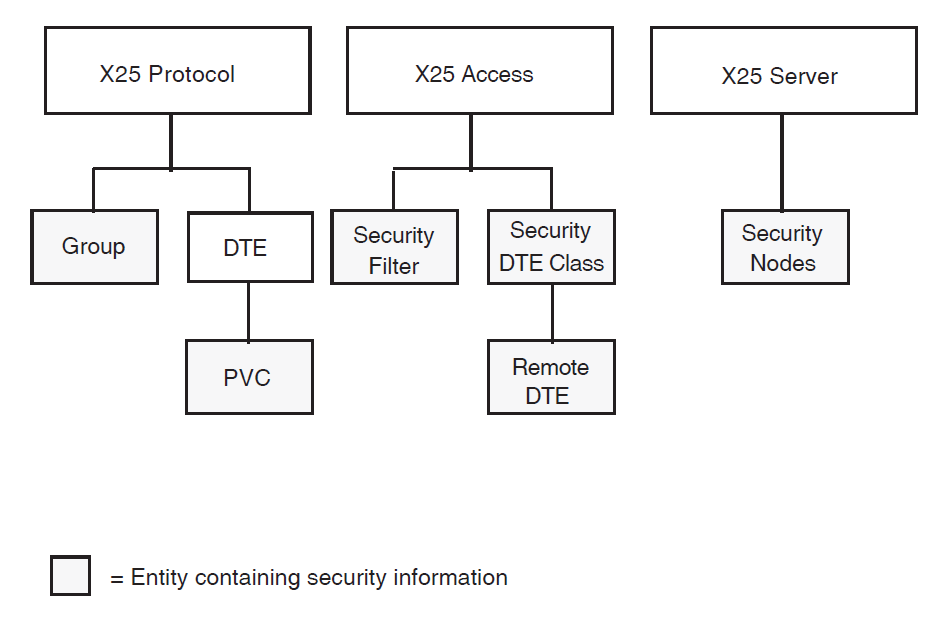
Security is designed within the framework of a distributed X.25 Security model. The X.25 Security model provides facilities for protecting:
Filters
DTE Classes (and hence remote DTEs)
Bilateral Closed User Groups (BCUGs)
Permanent Virtual Circuits (PVCs)
Connector systems
The entities used by X.25 Security are shown in Figure 2.1, ''Entities Used by X.25 Security'' and described further in the following sections.
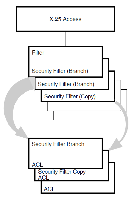
2.2. Filter Security
Access to a filter is controlled by a SECURITY FILTER entity associated with that filter. The SECURITY FILTER entity defines access control information (in the form of an Access Control List (ACL)) that determines whether to permit a caller (based on rights identifiers in the appropriate SECURITY DTE CLASS REMOTE DTE entity) access to the application associated with the filter.
As many SECURITY FILTER entities as necessary can be created. Each filter can have its own SECURITY FILTER entity or a single SECURITY FILTER entity can be used to protect all filters.
Figure 2.2, ''Filter Security'' shows the relationship between filters and associated
SECURITY FILTER entities. In this figure, two filters are protected by the SECURITY FILTER
entity Branch and a third filter is protected by the SECURITY FILTER entity
Copy.
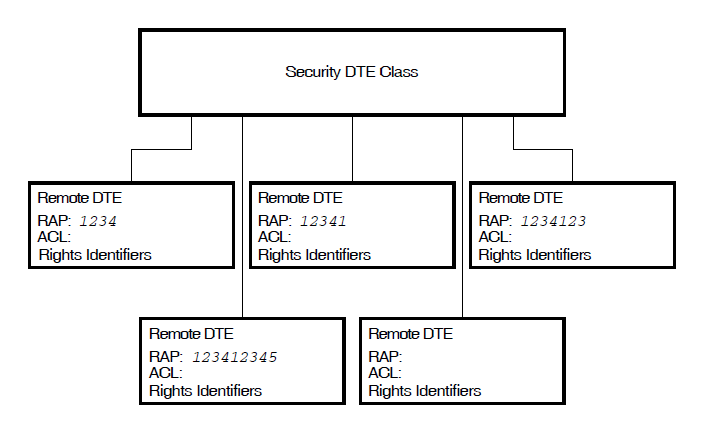
2.3. DTE Class Security
Access to a DTE class is controlled by a SECURITY DTE CLASS entity associated with that DTE class. Each SECURITY DTE CLASS entity can maintain several REMOTE DTE child entities which provide protection information for a specific DTE or all DTEs associated with a specified DTE class. Each DTE class can specify the name of a SECURITY DTE CLASS entity. The protection information for a DTE (defined by a REMOTE DTE entity) consists of:
A Remote Address Prefix (RAP), against which the remote DTE address in an incoming call or outgoing call is matched
Rights identifiers, which are used to define the rights that an incoming call is assigned (which control access to FILTER entities via their associated SECURITY FILTER entities, refer to Section 2.2, ''Filter Security'')
An Access Control List (ACL), which determines whether an outgoing call using the DTE class is permitted, based on the rights identifiers assigned to the calling process or SECURITY NODE entity
Figure 2.3, ''DTE Class Security'' shows the relationship between a SECURITY DTE CLASS entity and five SECURITY DTE CLASS REMOTE DTE entities.
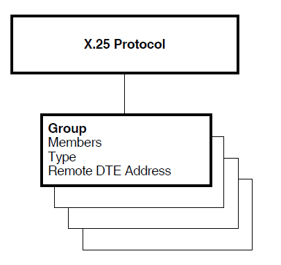
2.4. Bilateral Closed User Group Security
Note
This type of security is relevant only to X.25 Direct Connect and Connector systems.
This section applies only to members of Bilateral Closed User Groups (BCUGs). Members of regular Closed User Groups (CUGs) use the same X.25 Security methods used on normal incoming and outgoing calls as discussed in Section 2.2, ''Filter Security'' and Section 2.3, ''DTE Class Security''. To use a CUG member, you specify the DTE class, the group name, and the DTE address. Thus security is controlled by the specified DTE class and DTE address as with normal incoming and outgoing calls.
The security matching procedure that must be performed on calls between members of a Bilateral Closed User Group (BCUG) differs from that which is performed on normal incoming and outgoing calls. Although a DTE class is provided to X.25 for OpenVMS, no remote DTE address is passed to X.25 for OpenVMS or to the called DTE. Instead, the call is assumed to be incoming from, or outgoing to, the other DTE in the BCUG. To properly handle security on the local system, X.25 Security must know the remote DTE address so that it can use this address in the security matching procedure to determine whether the call request is permissible.
To provide the remote DTE address required by the X.25 Security algorithms, the X25 PROTOCOL GROUP entity is used. This entity defines the name of the BCUG, its sole local member, its type (BCUG), and the remote DTE address of the other DTE in the BCUG. The specified DTE class and the GROUP entity’s Remote DTE Address characteristic are used to identify the SECURITY DTE CLASS REMOTE DTE entity whose ACLs provide protection for the BCUG.
Details of the security matching procedure are given in Section 3.6, ''The ACL Matching Procedure''.
Figure 2.4, ''BCUG Group Security'' shows the X25 PROTOCOL GROUP entity.
2.5. Permanent Virtual Circuit Security
Note
This type of security is relevant only to X.25 Direct Connect and Connector systems.
A X25 PROTOCOL PVC entity defines the operation of a PVC that is associated with a DTE. A characteristic in the PVC entity defines an ACL that controls the use of that PVC.
Figure 2.5, ''PVC Security'' shows the structure of the PVC entity.
2.6. Connector System Security
The X25 SERVER SECURITY NODES entity contains a set of Distributed Name Service (DECdns) node full names and the rights identifiers associated with the set of nodes. This entity supplies the rights identifiers when agents make outgoing calls through Connector systems.
Figure 2.6, ''Connector System Security'' shows the structure of the SECURITY NODES entity.
Chapter 3. How the X.25 Security Model Is Used
3.1. Introduction
Different parts of the X.25 Security Model must interact to ensure that an X.25 for OpenVMS system is secure. This chapter describes how the X.25 Security model is used. Specifically, it describes how X.25 Security:
Verifies incoming calls (refer to Section 3.2, ''Verifying Incoming Calls'')
Verifies outgoing calls (refer to Section 3.3, ''Verifying Outgoing Calls'')
Verifies access to PVCs (refer to Section 3.4, ''Verifying Access to PVCs'')
Selects the REMOTE DTE entity to use (refer to Section 3.5, ''Remote DTE Entity Selection'')
Uses Access Control Lists (refer to Section 3.6, ''The ACL Matching Procedure'')
3.2. Verifying Incoming Calls
This section provides a general overview of the call verification procedure for incoming calls:
Section 3.2.1, ''Verifying Incoming Calls to an X.25 Direct Connect System'' describes how X.25 Security verifies incoming calls to an X.25 Direct Connect System.
Section 3.2.2, ''Verifying Incoming Calls to an X.25 Client System'' describes how X.25 Security verifies incoming calls to an X.25 Client System.
The descriptions detail how the entities described in Chapter 1, "Overview" and Chapter 2, "The X.25 Security Model" are used to verify calls.
The descriptions in Section 3.2.1, ''Verifying Incoming Calls to an X.25 Direct Connect System'' and Section 3.2.2, ''Verifying Incoming Calls to an X.25 Client System'' do not apply to calls between member DTEs of a Bilateral Closed User Group (BCUG). Details of how X.25 Security verifies such calls are given in Appendix A, "The X.25 Security Verification Procedures".
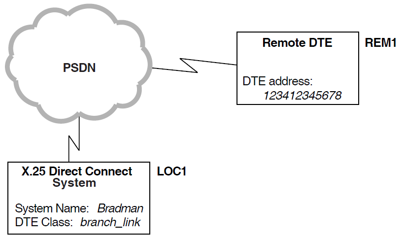
3.2.1. Verifying Incoming Calls to an X.25 Direct Connect System
This section describes how X.25 Security verifies an incoming call to an X.25 Direct Connect system, that is, a call from a remote DTE to the local DTE.
In the example shown in Figure 3.1, ''Example Incoming Call (X.25 Direct Connect Systems)'', remote DTE REM1 (DTE
address 123412345678) is attempting to make a call to an enquiry database
on the local DTE LOC1. Security on the local DTE is set up as shown in
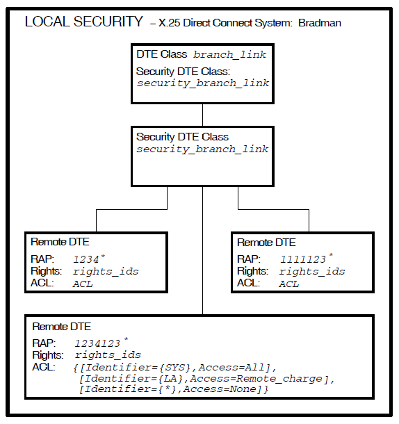
Figure 3.2, ''Local DTE Security (incoming calls)''.
The security set up shown in Figure 3.2, ''Local DTE Security (incoming calls)'' means that:
DTE CLASS entity
branch_linkis protected by the SECURITY DTE CLASS entitysecurity_branch_link. This is a placeholder for a number of REMOTE DTE entities, which are defined as child entities of the SECURITY DTE CLASS entity.The child entities identify the calling DTEs that are permitted to call the local DTE. Each REMOTE DTE entity has a Remote Address Prefix (RAP), which is used as a key when matching the DTE address of one of the calling DTEs to one of the REMOTE DTE entities. RAPs can include a wildcard ( * ) which matches any character (including a null character) or set of characters following the specified characters. For more information on how to use wildcards, refer to Section 3.5, ''Remote DTE Entity Selection''.
FILTER entity
enquiry_database(which is used to listen for calls to the enquiry database) is protected by the SECURITY FILTER entitysecurity_enquiry_database.
When an incoming call arrives for the local DTE, X.25 Security selects the REMOTE DTE entity having the RAP that most closely matches the calling DTE address. Then, X.25 Security assigns the rights identifiers from the selected REMOTE DTE entity to the incoming call. The DTE address matching process is described more fully in Section 3.5, ''Remote DTE Entity Selection''.
In the example shown in Figure 3.1, ''Example Incoming Call (X.25 Direct Connect Systems)'' and Figure 3.2, ''Local DTE Security (incoming calls)'', the
best match for remote DTE REM1 (DTE address 123412345678) is
the RAP 1234123*. This means that rights identifier
use_enquiry_db is assigned to the incoming call.
Once X.25 Security has assigned rights identifiers to the calling DTE, it:
Finds the filter that matches the call (from the call parameters). In this example, FILTER entity
enquiry_database.Finds the security filter associated with this filter. In this example, it is SECURITY FILTER entity
security_enquiry_database.Matches the rights identifier assigned to the calling DTE against the rights identifiers defined in the ACEs specified for the ACL of the security filter.
If there is a match, the Access field of the ACE is used by X.25 Security to determine what happens to the call. The call can be accepted or rejected.
If there is no match, X.25 Security clears the call.
ACL matching is described in Section 3.6, ''The ACL Matching Procedure''.
In the above example, the use_enquiry_db rights identifier matches with
the first ACE in the ACL of the SECURITY FILTER entity
security_enquiry_database. The access level associated with the rights
identifier use_enquiry_db is All. This means that the call is
permitted (refer to Table 1.1, ''Access Levels'').
3.2.2. Verifying Incoming Calls to an X.25 Client System
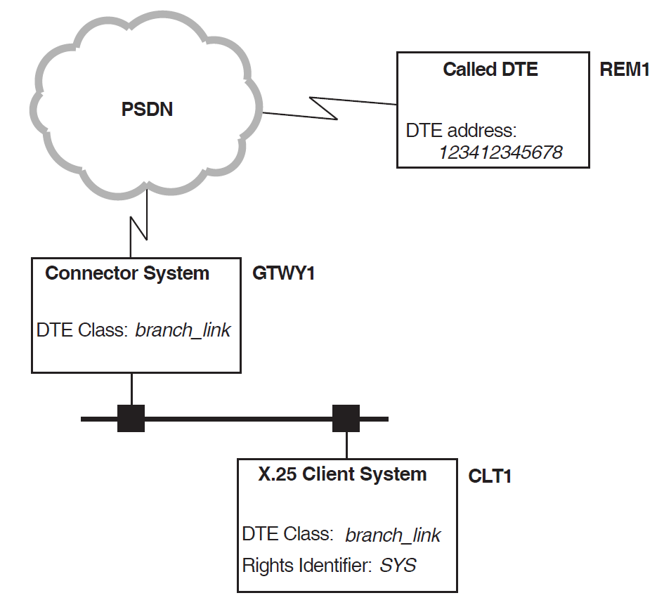
This section describes how X.25 Security verifies an incoming call to an X.25 Client system, that is, a call from a remote DTE that is forwarded by a Connector system to an X.25 Client system.
In the example shown in Figure 3.3, ''Example Incoming Call (X.25 Client Systems)'', remote DTE REM1 (DTE
address 123412345678) is attempting to make a call to an enquiry database
on X.25 Client system CLT1 via Connecter system GTWY1.
Security on the X.25 Client system (the local DTE) is identical to that shown in Figure 3.2, ''Local DTE Security (incoming calls)''.
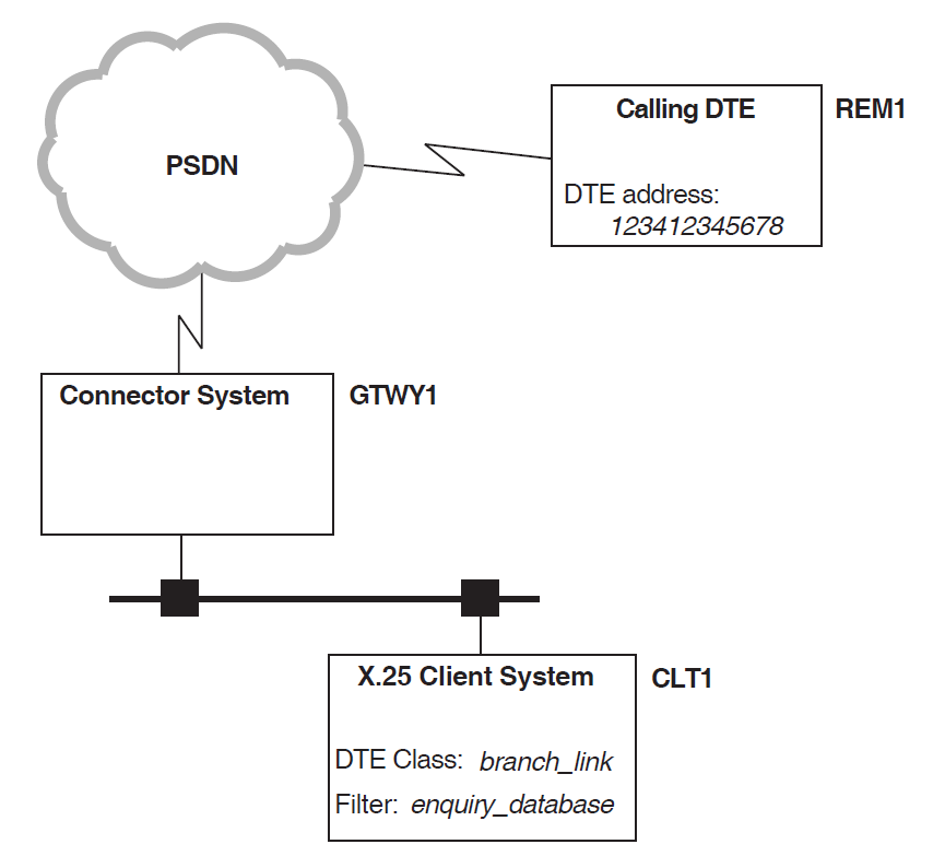
When an incoming call arrives for the X.25 Client system via the Connector system, X.25 Security selects the REMOTE DTE entity having the RAP that most closely matches the calling DTE address. Then, X.25 Security assigns the rights identifiers from the selected REMOTE DTE entity to the incoming call. The DTE address matching process is described more fully in Section 3.5, ''Remote DTE Entity Selection''.
In the above example, the best match for remote DTE REM1 (DTE address
123412345678) is the RAP 1234123*. This means that rights
identifier use_enquiry_db is assigned to the incoming call.
Once X.25 Security has assigned rights identifiers to the calling DTE, it:
Finds the filter that matches the call (from the call parameters). In this example, the FILTER entity
enquiry_database.Finds the security filter associated with this filter. In this example, the SECURITY FILTER entity
security_enquiry_database.Matches the rights identifier assigned to the calling DTE against the rights identifiers defined in the ACEs specified for the ACL of the security filter.
If there is a match, the Access field of the ACE is used by X.25 Security to determine what happens to the call. The call can be accepted or rejected.
If there is no match, X.25 Security clears the call.
ACL matching is described in Section 3.6, ''The ACL Matching Procedure''.
In the above example, the use_enquiry_db rights identifier matches with
the first ACE in the ACL of the SECURITY FILTER entity
security_enquiry_database. The access level associated with the rights
identifier use_enquiry_db is All. This means that the call is
permitted (refer to Table 1.1, ''Access Levels'').
3.3. Verifying Outgoing Calls
This section provides a general overview of the call verification procedure for outgoing calls:
Section 3.3.1, ''Verifying Outgoing Calls from an X.25 Direct Connect System'' describes how X.25 Security verifies outgoing calls from an X.25 Direct Connect System.
Section 3.3.2, ''Verifying Outgoing Calls from an X.25 Client System'' describes how X.25 Security verifies outgoing calls from an X.25 Client System.
The descriptions detail how the entities described in Chapter 1, "Overview" and Chapter 2, "The X.25 Security Model" are used to verify calls.
The descriptions in Section 3.3.1, ''Verifying Outgoing Calls from an X.25 Direct Connect System'' and Section 3.2.2, ''Verifying Incoming Calls to an X.25 Client System'' do not apply to calls between member DTEs of a Bilateral Closed User Group (BCUG). Details of how X.25 Security verifies such calls are given in Appendix A, "The X.25 Security Verification Procedures".
3.3.1. Verifying Outgoing Calls from an X.25 Direct Connect System
This section explains how X.25 Security verifies an outgoing call from an X.25 Direct Connect system, that is, from a local DTE connected directly to a PSDN.
In Figure 3.4, ''Example Outgoing Call (X.25 Direct Connect System)'' a user of the local DTE LOC1 is attempting
to call remote DTE REM1 (DTE address 123412345678). Security
is set up as shown in Figure 3.5, ''Local DTE Security (outgoing calls)''.
On the local DTE, X.25 Security looks in the file
SYS$SYSTEM:RIGHTSLIST.DAT for the rights identifiers associated
with the user’s process. For this example, the rights identifier associated with the
user’s process is SYS.
X.25 Security then:
Finds the DTE CLASS entity (
branch_link) to use for the outgoing call. This is specified in the user’s request, or in a template.Finds the SECURITY DTE CLASS entity (
security_branch_link) specified in the DTE CLASS entity (if it does not exist, the call fails).Matches the called DTE address in the call request (
123412345678) against the RAP attributes of the available SECURITY DTE CLASS REMOTE DTE entities. The matching process is described in Section 3.5, ''Remote DTE Entity Selection''.Finds a RAP (
1234123*) that best matches the called DTE address (if there is no matching RAP, the call fails).Matches the rights identifiers for the process that requested the call (
SYS) with the rights identifiers defined in the ACEs in the ACL belonging to the REMOTE DTE entity.Uses the Access field of the ACE (
Access=All) to determine what to do with the call.
If the verifications are successful, the call is passed to the PSDN.
To summarize the preceding example, remote DTE REM1 (DTE address
123412345678) matches the REMOTE DTE entity having a RAP of
1234123*. The rights identifier SYS matches with the first
ACE in the ACL. The access level associated with the rights identifier SYS
is Access = ALL, which means that the call is permitted.
3.3.2. Verifying Outgoing Calls from an X.25 Client System
For outgoing calls from an X.25 Client system, X.25 Security performs two verifications; one at the X.25 Client system and one at the Connector system.
At the X.25 Client system, X.25 Security looks in the file
SYS$SYSTEM:RIGHTSLIST.DATfor the rights identifiers associated with the user’s process. For this example, the rights identifiers associated with the user’s process isSYS.At the Connector system, X.25 Security obtains rights identifiers from a SECURITY NODES entity.
In the example shown in Figure 3.6, ''Example Outgoing Call from an X.25 Client System'', X.25 Client system
CLT1 is attempting to make a call to remote DTE REM1 (DTE
address 123412345678) through Connector system GTWY1.
Security on the X.25 Client system is set up as shown in Figure 3.7, ''X.25 Client System Security''.
X.25 Security looks in SYS$SYSTEM:RIGHTSLIST.DAT for the rights
identifiers associated with the process. X.25 Security then:
Finds the DTE CLASS entity (
branch_link) to use for the outgoing call. This is specified in the user’s request or in a template. Note the DTE class name must match a DTE CLASS entity with the exact same name on the Connector system.Finds the SECURITY DTE CLASS entity (
client_branch_link) specified in the DTE CLASS entity. If it does not exist, the call fails.Matches the called DTE address (
123412345678) in the request against the RAP attributes of the SECURITY DTE CLASS REMOTE DTE entities. The matching process is described in Section 3.5, ''Remote DTE Entity Selection''.Finds a RAP (
1234123*) that best matches the called DTE address. If there is no matching RAP, the call fails.Matches the rights identifiers (
SYS) for the process that requested the call with the Identifier fields of the ACEs in the ACL belonging to the remote DTE.Uses the Access field of the ACE (
Access =
                  All
) to determine what to do with the call.
If the verifications are successful, the call is passed to the Connector system.
To summarize the preceding example, DTE CLASS entity branch_link is
used for the outgoing call. Associated with this DTE class is SECURITY DTE CLASS entity
client_branch_link which has three SECURITY DTE CLASS REMOTE DTE
entities. Remote DTE 123412345678 best matches the REMOTE DTE entity with a
RAP of 1234123*. The SYS rights identifier of the process that
initiated the call matches with the first ACE in the ACL of RAP 1234123*.
The Access field of this ACE is Access = All, which means that the call is
permitted by the X.25 Client system and is forwarded to the Connector system.
Security on the Connector system is set up as shown in Figure 3.8, ''Connector System Security''.
At the Connector system, X.25 Security performs another verification. Each Connector system has one or more SECURITY NODES entities, which contain DECdns node names and the rights identifiers associated with them. The DECdns node names are the names of the X.25 Client systems to be granted the associated rights identifiers.
When an outgoing call reaches a Connector system, X.25 Security:
Searches the SECURITY NODES entities to find a node name that matches the X.25 Client system’s node name (
DEC:.eng.comms.clt1).When it finds a match, associates the rights identifier (
call_branch) in the SECURITY NODES entity with the call request.Finds the DTE CLASS entity (
branch_link) to use for the outgoing call. This is specified in the call request. Note the DTE class name must match a DTE CLASS entity with the exact same name on the Client system.Finds the SECURITY DTE CLASS entity (
security_branch_link). If it does not exist, the call fails.Matches the Called DTE Address field in the call request (
123412345678) against the RAP of the SECURITY DTE CLASS REMOTE DTE entities. The matching process is described in Section 3.5, ''Remote DTE Entity Selection''.Finds a RAP (
1234123*) that best matches the called DTE address (if there is no matching RAP, the call fails).Matches the rights identifier for the call (
call_branch) with the Identifier fields of the ACEs in the ACL belonging to the remote DTE.When it finds a match, uses the Access field in the ACE (
Access = All) to determine what to do with the call.
To summarize the preceding example, the agent on X.25 Client system
CLT1 is given the rights identifiers call_branch at the
Connector system. Remote DTE 12312345678 best matches the REMOTE DTE entity
with a RAP of 1234123*. The call_branch rights identifier
matches with the first ACE in the ACL. The Access field of this ACE is Access =
All, which means that the call is permitted by the Connector system and is sent
to the remote DTE.
3.4. Verifying Access to PVCs
Note
Verification of access to PVCs is relevant only to X.25 Direct Connect and Connector systems.
X.25 Security determines whether an application is permitted access to a PVC. Verification is made at the X.25 Direct Connect or Connector system where the PVCs exist.
Each PVC entity has an ACL that controls access to the PVC. To determine the access to a PVC, X.25 Security:
Finds the rights identifiers to associate with the user:
On X.25 Direct Connect systems, X.25 Security looks in the OpenVMS file
SYS$SYSTEM:RIGHTSLIST.DATfor the rights identifiers.On X.25 Connector systems, X.25 Security finds rights identifiers from the SECURITY NODES entity (refer to Section 3.3.2, ''Verifying Outgoing Calls from an X.25 Client System'');
Finds the PVC entity to use from the PVC access request.
Matches the rights identifiers for the user that requested access to the PVC with the Identifier fields of ACEs in the ACL belonging to the PVC entity.
When it finds a match, uses the Access field in the selected ACE to determine what to do with the call.
3.5. Remote DTE Entity Selection
Each SECURITY DTE CLASS entity should have at least one subordinate/child REMOTE DTE entity. Each REMOTE DTE entity contains a remote address prefix (RAP) and the ACL associated with that prefix. The RAP can be a wildcard ( * ), or a series of digits from 0 to 9, or a combination of both. The wildcard can be positioned anywhere in the series of digits. Figure 3.9, ''Remote DTEs with Valid RAPs'' shows examples of valid RAPs.
To find the rights identifiers and the ACL associated with a DTE address, the DTE address matching algorithm examines each of the available REMOTE DTE entities of the SECURITY DTE CLASS entity. The RAP of each REMOTE DTE entity is compared to the called or calling DTE address and the best match determined.
The RAP matching algorithm defines a best match as the longest
sequence of matching digits from the start of the RAP, between the RAP and
the DTE address. For example, suppose that the DTE address 123456789 is being
verified against the following RAPs:
        RAP : *
        RAP : 1*
        RAP : 123*
        RAP : 123456
        RAP : 123456*
DTE Address : 123456789
The best match is the RAP of 123456* because it has the longest sequence
of matching digits.
If there is no match for the DTE address, X.25 Security selects the REMOTE DTE entity with the wildcard RAP (RAP : *). X.25 Security also selects the REMOTE DTE entity with the wildcard RAP if the DTE address is null.
If there is no match and no wildcard RAP, X.25 Security clears the call.
As a further example of the matching process, suppose that your system has the REMOTE
DTE entities shown in Figure 3.9, ''Remote DTEs with Valid RAPs'' and the called or calling DTE address is
123412333333. X.25 Security selects the REMOTE DTE entity with the RAP
1234123* as the best match.
3.6. The ACL Matching Procedure
The ACL matching procedure is performed only after a REMOTE DTE entity has been selected (refer to Section 3.5, ''Remote DTE Entity Selection'').
The X.25 Security ACL verification procedure uses the same algorithm for incoming and outgoing calls. X.25 Security performs a search of the ACL and attempts to match the rights identifiers possessed by the agent with the set of rights identifiers possessed by each ACE in the ACL. For a match to be successful, the agent must possess all the rights identifiers specified in one of the ACEs. If the agent contains additional rights identifiers (over and above those defined in the matching ACE) they are ignored. Table 3.1, ''ACL Matching'' shows the possible outcomes of a search.
| Search Result | Level |
|---|---|
| Match found | The ACE is selected and the search terminated. The Access field of the ACE determines what happens to the call. |
| Match not found | The access level is taken as being None. |
| The rights identifier of an ACE is a wildcard | Any set of agent rights is taken as matching this ACE. The Access field of the ACE determines what happens to the call. |
To illustrate the ACL matching procedure, the following example shows the outcome of attempts to match a number of agent rights identifiers with the following ACL:
ACL = {[Identifier = {AA,BB,DD}, Access = All],
       [Identifier = {CC}, Access = Remote_Charge],
[Identifier = {*}, Access = None]} | Agent Rights Identifiers | Result of ACL Matching Procedure |
|---|---|
CC | Match found (second ACE); search terminated; call permitted only on a remote charge basis. |
AA,BB,DD | Match found (first ACE); search terminated; call permitted without restrictions. |
AA,BB | Match found (third ACE); search terminated; call not permitted. The agent’s rights identifiers do not match the first ACE as the agent does not possess all the rights identifiers specified. |
GG | Match found (third ACE); search terminated; call not permitted. |
CC,FF | Match found (second ACE)—identifier FF is ignored; search
terminated; call permitted only on a remote charge basis. |
3.6.1. Null ACLs
A null ACL is an ACL without entries and is represented using the following format:
{ } A null ACL does not allow any agents to have access to the objects it protects and is equivalent to the following match-all ACL:
{[Identifier = {*}, Access = None]}This ACL has a wildcard rights identifier that matches any set of agent rights identifiers and an access level that does not permit calls to be accepted.
Whenever an entity is created, it is assigned a null ACL. This ensures that system objects have maximum protection as soon as the associated entities are created. The null ACL remains in effect until an alternative, more specific, ACL is defined (set) for the entity.
3.6.2. Null Rights Identifiers
If no rights identifiers have been defined for a remote DTE, that DTE is said to have a null rights identifier.
Null rights identifiers match wildcard ACEs. For example, if the following ACE has been defined:
{[Identifier = {*}, Access = level]} then the wildcard ( * ) matches all occurrences of zero or more characters and
therefore encompasses the null rights identifier. In this case, the access level given
to the null rights identifier is specified by level, where
level is All,
Remote_Charge, or None.
3.6.3. The Order of ACL Entries
The order of ACEs in an ACL is important. The ACL matching algorithm searches each ACE in turn for the first rights identifier match it can find. When a match is found, the search is terminated. If a match occurs in an ACE specified later in the ACL, it is ignored.
ACLs can be created to provide several levels of protection to system objects. However, care must be taken to position ACEs in an ACL so that the greatest protection occurs nearest the end of the ACL. For example, you may want to apply greater protection to calls that you pay for than to calls that the remote DTE pays for. In this case, you would define ACEs in the ACL of the REMOTE DTE entity in the order shown in Figure 3.10, ''The Ordering of ACL Entries''.
The ACEs in Figure 3.10, ''The Ordering of ACL Entries'' ensure that:
Agents with the rights identifier 21 can make outgoing reverse charge calls and accept incoming non-reverse charge calls.
Agents with the rights identifier 22 can make any type of call.
Agents with rights identifiers other than 21 or 22 match with the wildcard entry and are not permitted to make or accept calls.
Part II. How to Manage X.25 Security
This part of the manual explains how to manage X.25 Security. Each section is task oriented. This part of the manual assumes that:
You have installed and configured X.25 for OpenVMS.
Your system is operational.
You have read the VSI X.25 for OpenVMS Management Guide.
You have the VSI DECnet-Plus for OpenVMS Network Control Language Reference manual available to obtain full details of NCL commands. This manual is needed only if you intend to edit the NCL script produced by the configuration program or intend to enter NCL commands interactively.
You have read Part I,''Introductory Information'' of this manual.
Chapter 4. Managing X.25 Security
4.1. Introduction
This chapter describes the tasks you will need to perform to plan and manage X.25 Security. General X.25 management tasks (for example, managing filters and DTE classes) are described in the VSI X.25 for OpenVMS Management Guide.
On OpenVMS IA-64 or Alpha systems, to change the security of your X.25 system, do one of the following:
Run the ADVANCED mode of the configuration program, revising the current security definitions, and then reboot the system.
Override the current security definitions with new ones defined in the relevant user NCL script file and then execute the revised user NCL script files.
Issue NCL commands interactively.
Note
It is recommended that changes to security be made by performing one of the first two actions as these are the only methods which ensure that the specified security is used each time the system is booted. The third method makes only temporary changes to security; such changes are lost the next time the system is booted.
For details on using the X.25 configuration program, refer to the VSI X.25 for OpenVMS Configuration Guide. For details of issuing NCL commands interactively, refer to the VSI X.25 for OpenVMS Management Guide. Full details of the syntax of each NCL command are given in the VSI DECnet-Plus for OpenVMS Network Control Language Reference manual.
On OpenVMS VAX systems, to change the security of your X.25 system, do one of the following:
Run the configuration program, revise the current security definitions, and then reboot the system.
Override the current security definitions with new ones defined in the NCL script file and then execute the revised NCL script file.
Issue NCL commands interactively.
Note
It is recommended that changes to security are made by using the configuration program as this is the only method which ensures that the specified security is used each time the system is booted. Issuing NCL commands interactively makes only temporary changes to security; such changes are lost the next time the system is booted.
For details on using the X.25 configuration program, refer to the VSI X.25 for OpenVMS Configuration Guide. For details of issuing NCL commands interactively, refer to the VSI X.25 for OpenVMS Management Guide. Full details of the syntax of each NCL command are given in the VSI DECnet-Plus for OpenVMS Network Control Language Reference manual.
4.2. Planning Security for Your System
To control incoming and outgoing calls, you need to:
Create SECURITY FILTER entities to protect the filters on your system.
Create SECURITY DTE CLASS entities (and REMOTE DTE child entities) to protect the DTEs on your system.
Set the ACLs in the X25 PROTOCOL DTE PVC entities to specify who can access PVCs.
Set the Remote DTE Address attribute of the X25 PROTOCOL GROUP entities (type BCUG only) to match the X25 ACCESS SECURITY DTE CLASS REMOTE DTE entity that is to control access to the group.
Specify which nodes can use Connector nodes by setting up X25 SERVER SECURITY NODES entities.
4.2.1. Planning Filter Security
If you have the same security requirements for all the filters on your system, you need only create one SECURITY FILTER entity. In this security filter, specify an ACL to control access. Once you have defined the security filter, you will need to modify the Security Filter characteristic of each FILTER entity so that it points to the defined security filter.
If you have different security requirements for different filters, you should create
more than one security filter. For example, suppose you have defined two filters, called
x29 and app, that listen for calls to applications
x.29 and app and you want to allow all agents to use
application app but restrict access to application x.29. In
this case, you should set up the following SECURITY FILTER entities:
app_security, having the ACL:{[Identifier = {*}, Access = All]}This ACL allows agents with any rights identifiers access to the FILTER entity
app.x29_security, having the ACL:{[Identifier = {USE_X29}, Access = All], [Identifier = {*}, Access = None]}This ACL restricts the use of the FILTER entity
x29to agents with theUSE_X29rights identifier; agents not having this identifier are not permitted to access the filterx29.
By using several security filters, you can clearly define the security requirements for each filter.
The following example details the NCL commands required to set up incoming call security for the example just described:
ncl> create x25 access security filter APP_SECURITY
ncl> set x25 access security filter APP_SECURITY ACL -
_ncl> {[Identifier={*}, Access=All]}
ncl> create x25 access security filter X29_SECURITY
ncl> set x25 access security filter X29_SECURITY ACL -
_ncl> {[Identifier={USE_X29}, Access=All], [Identifier={*}, Access=None]}
ncl> set x25 Access filter APP security filter APP_SECURITY
ncl> set x25 Access filter x29 security filter x29_SECURITY
ncl>
4.2.2. Planning DTE Class and Remote DTE Security
Each SECURITY DTE CLASS entity is a parent for the SECURITY DTE CLASS REMOTE DTE entities associated with it. You can create one or more SECURITY DTE CLASS entities on your system.
The number of REMOTE DTE entities you need to set up depends on your security requirements. For example, if you want all the DTEs in a particular network to have the same rights identifiers and be controlled by the same ACL, you can set up a single REMOTE DTE entity having the Data Network Identification Code (DNIC) of the network. Note that DNICs apply only to public networks.
If you want to specify different security levels for different DTEs or groups of DTEs you need to set up REMOTE DTE entities for several DTE address prefixes. For example, you could create REMOTE DTE entities with the following prefixes:
123412345678123412345677 1234123*
1234113* 1234*
| These are full DTE addresses. Creating REMOTE DTE entities with full DTE address prefixes allows you to define the security information for a specific DTE. |
| These address prefixes could be for DTEs from specific areas. Creating REMOTE DTE entities like this allows you to define security information for a specific group of DTEs. |
| This address prefix is a DNIC. Creating a REMOTE DTE entity with a DNIC prefix allows you to define security information for all the DTEs in a public network. |
In general, the finer the security control required, the greater the number of REMOTE DTE entities that must be defined.
SECURITY DTE CLASS entities should be set up using the X.25 for OpenVMS configuration program. See Section 4.1, ''Introduction'' for information about using the X.25 configuration program.
Alternatively, NCL commands can be issued interactively. For example, suppose you
want to set up outgoing security to a DTE class called galaxy so that only
users with the rights identifier AUSTPAC are permitted to make calls. This
can be achieved using the following NCL commands:
ncl> create x25 access security dte class sec-1ncl> set x25 access dte class galaxy security dte class sec-1
| Creates SECURITY DTE CLASS entity |
| Create REMOTE DTE entity |
| Defines the ACL for REMOTE DTE entity |
| Assign the SECURITY DTE CLASS entity |
4.2.3. Planning PVC Security
Security information is part of an X25 PROTOCOL DTE PVC entity. You need to work out who you want to be able to use a PVC and then set up an ACL to control access.
Note that for PVCs, the REMOTE_CHARGE access level provides the same access as ALL.
4.2.4. Planning Group Security
Note
Closed User Group (CUG) security can only be set up on the Direct Connect or Connector systems; X25 PROTOCOL GROUP entities cannot be defined on X.25 Client systems.
Planning security for members of a normal Closed User Group (CUG) is no different than planning security for individual remote DTEs. When you use a member of a CUG, you must specify the DTE class, the group, and the remote DTE address. As with individual DTEs, the DTE class specifies a DTE CLASS entity whose Security DTE Class attribute specifies a SECURITY DTE CLASS entity. The REMOTE DTE child entities of the SECURITY DTE CLASS entity and the supplied remote DTE address are used in the address matching process described in Section 4.2.1, ''Planning Filter Security'' and Section 4.2.2, ''Planning DTE Class and Remote DTE Security''. In this case, the CUG group does not hold any security information. However, it does result in the connection using the CUG facilities offered by the PSDN. In point-to-point connections, the group index number is simply passed to the remote DTE in the Facilities field of the Call packet.
Bilateral Closed User Groups (BCUGs) differ from CUGs in that they consist of only two DTEs, one of which is a member of a GROUP entity on the local system. Therefore, the remote DTE is uniquely identified by the use of the BCUG; no remote DTE address is necessary. However, for local security purposes, the address of the remote DTE address must be known. To set up BCUG group security, you must define in the GROUP entity the exact DTE address of the remote DTE in the specified BCUG. In this sense, even though they do not directly contain rights identifiers or ACLs, BCUG GROUP entities indirectly control security on the local system.
BCUG group security should be set up using the X.25 configuration program. See Section 4.1, ''Introduction'' for information about using the X.25 configuration program.
Alternatively, you can enter NCL commands interactively. For example, to define
group security for BCUG bistar that contains this system and another system
having the DTE address 123456, enter the following commands:
ncl> create x25 protocol group bistar
| Creates Group |
| Sets the type of the group to BCUG. |
| Sets the DTE address of the other system in the BCUG to |
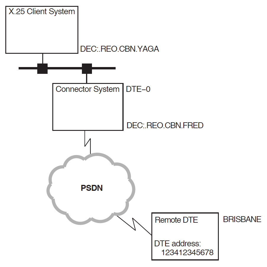
4.3. Example Security Setup
This section uses a simple example configuration to show how to use NCL to configure the security-related components of an X.25 system. Figure 4.1, ''Example Configuration'' shows the example configuration.
The example configuration consists of two DTEs:
A local DTE on the Connector system
DEC:.REO.CBN.FRED. An X.25 Client system,DEC:.REO.CBN.YAGA, uses this DTE on the Connector system to gain access to the PSDN.A remote DTE called
BRISBANE, with DTE address123412345678.
The NCL script following Figure 4.1, ''Example Configuration'' sets up security for this configuration.
The following NCL script extract illustrates the NCL commands to set up security on the Connector system for the configuration shown in Figure 4.1, ''Example Configuration''. Notes about the NCL commands are provided after the NCL script.
. . . create x25 access security DTE class austpacacl { - (identifiers=(walter), access=all), - (identifiers=(davison), access=all), - (identifiers=(managers), access=all), - (identifiers=(waters), access=remote_charge), - (identifiers=(walker), access=remote_charge), - (identifiers=(*), access=none) - } create x25 access security filter x25$mail
set x25 access security filter x25$mail - acl { - ( identifiers=(x25$mail), access=all ), -
( identifiers=(*), access=none) } create x25 server security nodes access-managers
set x25 server security nodes access-managers - rights identifiers { managers }
set x25 server security nodes access-managers nodes - { DEC:.REO.CBN.YAGA }
set x25 protocol dte dte-0 pvc pvc-0 -
acl { - (identifiers=(walter), access=all), - (identifiers=(davison), access=all), - (identifiers=(managers), access=all), - (identifiers=(*), access=none) - } set x25 protocol group brisbane_group -
remote dte address 123412345678 set x25 access dte class austpac security dte class austpac
set x25 access filter x25$mail security filter x25$mail
. . .
| The local system supports a single DTE CLASS entity, |
| This command creates a REMOTE DTE entity ( |
| This command specifies that incoming calls from remote DTE |
| This command sets the ACL for the REMOTE DTE entity |
| This command creates the SECURITY FILTER entity |
| This command specifies the access to be granted to incoming calls to the
application |
| This command creates a SECURITY NODES entity, which is used to control access to the network by a set of Client systems using this Connector system. |
| This command specifies that the rights identifier |
| This command associates the SECURITY NODES entity |
| This command specifies the ACL that controls access by local users to the PVC
called |
| This command sets up group security for a bilateral closed user group consisting
of the local DTE and remote DTE |
| This command specifies that security for the DTE CLASS entity |
| This command specifies that security for the FILTER entity |
4.4. Setting Up an Open System
An open system is one that allows any agent access to any object. By setting up an open system you are, in effect, turning off security on your system.
To set up an open system, define the following ACL:
{[Identifier = {*}, Access = All]}for the following entities:
SECURITY FILTER
REMOTE DTE
PVC (Direct Connect and Connector systems only)
The entities and their corresponding ACLs should be set up by running the X.25 for OpenVMS configuration program.
Alternatively, you can enter NCL commands interactively. For example, to set up an
open system for the REMOTE DTE entity fred, enter the following
commands:
ncl> create x25 access security filter open
ncl> set x25 access security filter open -
_ncl> acl {[Identifier = {*}, Access = All]}
ncl> set x25 access filter * security filter open
ncl> create x25 access security dte class open
ncl> create x25 access security dte class open remote dte fred -
_ncl> remote address prefix *
ncl> set x25 access security dte class open remote dte fred -
_ncl> acl {[Identifier = {*}, Access = All]}
ncl> set x25 access dte class * security dte class open
You will also need to assign at least one rights identifier to entities that contain a rights identifier list; these entities being:
REMOTE DTE
SECURITY NODES (for Connector systems only)
For example:
ncl> set x25 access security dte class default remote dte match_all -
_ncl> rights identifiers (network)
ncl> set x25 server security nodes all_nodes -
_ncl> rights identifiers (network)
Chapter 5. Monitoring X.25 Security
5.1. Introduction
Once you have set up security, you must monitor the system regularly to verify that your system is secured as you intended and to detect:
Any unauthorized attempts to access your system
Any attempts by unauthorized users to make calls from your system
Security problems can be accidental or malicious. An accidental problem is probably the result of an error in an ACL, causing a rights identifier match to fail. A malicious problem is caused by unauthorized users attempting to make calls to or from your system.
X.25 Security allows you to monitor your system and to correct these problems.
5.2. Monitoring Security
To monitor security, you can:
Set up event logging to monitor events
Look at entity counters
Look at the status of entities
Use the X.25 Accounting utility
Appendix A, "The X.25 Security Verification Procedures" describes the X.25 Security call verification procedures and describes the events generated and the counters that are incremented when each type of verification fails.
You can monitor incoming and outgoing calls using the X.25 Accounting utility. Details of this utility are given in the VSI X.25 for OpenVMS Accounting manual.
5.2.1. Security Events
An event log contains messages that record changes in the status of the system. For example, every time security blocks an incoming call, an event message is logged. Event logging is the primary tool for monitoring and problem solving your system. The VSI DECnet-Plus for OpenVMS Network Management Guide describes how to set up event logging on your system. X.25 Security-specific events are described in Appendix B, "X.25 Security Events".
5.2.2. Security Counters
The X25 Access module maintains several security counters which record the number of times security blocked access to or from your system. The X25 Access counters are described in Table 5.1, ''X.25 Access Module Security Counters''.
| Counter | Description |
|---|---|
| Incoming Calls Blocked | The total number of incoming calls blocked by security. |
| Outgoing Calls Blocked | The total number of outgoing calls blocked by security. |
| Outgoing Call Configuration Errors | The total number of times outgoing calls failed because of the misconfiguration of the security management databases. |
| PVC Accesses Blocked | The total number of PVC accesses blocked by security. |
In addition to the counters maintained by X25 Access, some of the X.25 Security entities maintain counters. These counters are described in Table 5.2, ''Entity-Specific Security Counters''.
| Entity | Counter | Description |
|---|---|---|
| FILTER | Incoming Calls Blocked | The total number of times security has blocked an incoming call that matched the specified filter. |
| REMOTE DTE | Incoming Calls Blocked |
Incoming Calls Blocked The total number of times security has blocked an incoming call that matched the RAP on the specified remote DTE. |
| Outgoing Calls Blocked | The total number of times security has blocked an outgoing call that specified a destination DTE address that matched the RAP on the specified remote DTE. | |
| SECURITY NODES | Outgoing Calls Blocked | The total number of times that security has blocked outgoing calls or PVC access requests from nodes represented by the specified entity. |
| PVC | Accesses Blocked | Accesses Blocked The total number of times security has blocked access to this PVC. |
| GROUP | Incoming Calls Blocked | Incoming Calls Blocked The total number of times security has stopped a call that specified the named BCUG from accessing a filter. |
| Outgoing Calls Blocked | Outgoing Calls Blocked The total number of times security has blocked an outgoing call that used the named BCUG. |
5.2.3. Monitoring Events and Counters
You can find out about security problems on your system in three ways:
View the event logs.
View the X25 Access module or entity-specific counters to see if any of them have recorded a large number of blocked calls.
Analyze the output from the X.25 for OpenVMS Accounting utility.
If you notice a security problem, look at the event that was generated.
If the problem was caused by an incoming call:
Look at the event to determine:
Which application was attacked
The source of the attack
Look at the counters on the filter and remote DTE and try to correlate them with the events.
Take action to solve the problem. If the calling DTE should be allowed to make calls to the destination on your system that it attempted to call, examine the ACL associated with the FILTER entity and the rights identifiers associated with the REMOTE DTE entities.
If the call was blocked correctly, and the problem recurs, contact the relevant PSDN authority and notify them of the problem.
If the problem was caused by an outgoing call:
Look at the event to determine:
The source of the call
The destination DTE
Look at the counters on the remote DTE or group and correlate them with the events.
Take action to solve the problem. If the call should have succeeded, examine the ACLs associated with the REMOTE DTE or GROUP entities. Also, verify that the agent has the correct rights identifiers.
If security blocked the call correctly, locate the initiator of the call and take the appropriate action to rectify the problem.
5.2.4. Monitoring the Status of Security Entities
The SECURITY DTE CLASS and the SECURITY FILTER entities have the status attributes shown in Table 5.3, ''Status Attributes''.
| Entity | Status Attribute | Description |
|---|---|---|
| SECURITY DTE CLASS | Guarded DTE Classes | The names of the DTE CLASS entities protected by this SECURITY DTE CLASS entity. |
| SECURITY FILTER | Guarded Filters | The names of the FILTER entities protected by this SECURITY FILTER entity. |
Use these status attributes to verify your security set-up. For example, the
following command displays the DTE CLASS entities guarded by the SECURITY DTE CLASS
entity x121:
ncl> show x25 access security dte class x121 all status
5.2.5. Monitoring Match-all Security
If you have set up match-all ACLs, for example, to block calls from particular countries, you will have set up ACLs similar to the following example:
{[Identifier = {*}, Access = None]}If you have ACLs like this associated with short remote address prefixes (for example, DNIC only) and you find a large number of incoming call blocked events, you will need to locate the specific DTEs attempting to break into your system. Look at the event log to find out which remote DTE is attempting to break into your system. Monitor the specific remote DTE by setting up a REMOTE DTE entity with the full DTE address of the suspect DTE as the RAP. Specify no access on the ACL you associate with the RAP. For example:
ncl> create x25 access security -
_ncl> dte class bill remote dte catch-hacker -
_ncl> remote address prefix 123412345678
ncl> set x25 access security dte -
_ncl> class bill remote dte catch-hacker acl -
_ncl> {[Identifier = {*}, Access = None]}
If you do not have the event logs available, you can find out a specific remote DTE by a process of elimination. For example, if you have a large number of incoming access blocked events on a REMOTE DTE entity with the RAP 1234, determine the address of the remote DTE attempting to break-in as follows:
Set up REMOTE DTE entities with the following prefixes:
1234
12340
12341
   .
   .
   .
12349
For each entity, specify the Access field of the ACE as
Nonefor any calling DTE.Monitor the counters to find out which REMOTE DTE entity registers break-in attempts.
Repeat step 1 by adding one more digit to the prefix you identify and deleting all the ones you have discounted. For example:
1234
123410
123411
123412
   .
   .
   .
123419
Repeat the process until you have identified the DTE address of the problem DTE.
Part III. Reference Information
Appendix A. The X.25 Security Verification Procedures
This appendix describes how X.25 Security verifies:
Outgoing calls (Section A.1, ''Verifying Outgoing Calls'')
Outgoing calls using BCUGs (Section A.2, ''Verifying Outgoing Calls Using Bilateral Closed User Groups'')
Incoming calls (Section A.3, ''Verifying Incoming Calls'')
Incoming calls using BCUGs (Section A.4, ''Verifying Incoming Calls Using Bilateral Closed User Groups'')
Access to PVCs (Section A.5, ''Verifying Access to Permanent Virtual Circuits'')
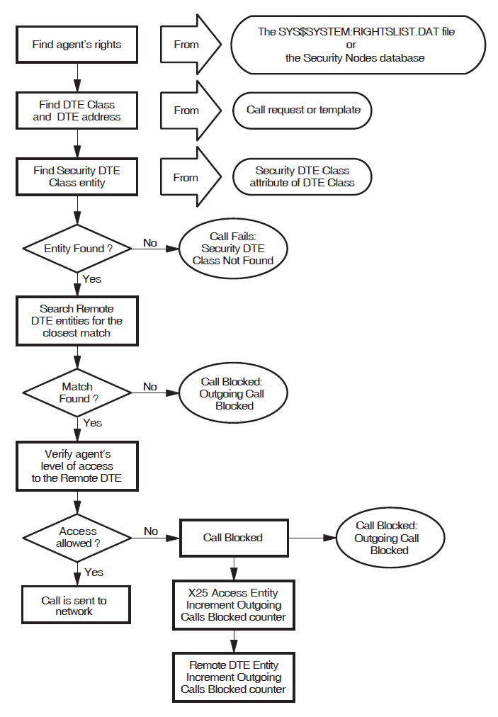
A.1. Verifying Outgoing Calls
This section describes how X.25 Security verifies outgoing calls. Any differences in the verification procedure for different types of system (X.25 Direct Connect, X.25 Client, or Connector) are identified. This section does not apply to outgoing calls that specify a BCUG or a PVC.
Figure A.1, ''How X.25 Security Verifies Outgoing Calls'' illustrates the outgoing call verification procedure.
A.1.1. Finding the Agent’s Rights Identifiers
- Local System
The rights identifiers are relevant only to the local node (on Client systems they are not passed between the X.25 Client system and the Connector system). The identifiers are defined in the file
SYS$SYSTEM:RIGHTSLIST.DAT.- Connector System
When X25 Server is the agent, X.25 Security finds the rights identifiers from in the SECURITY NODES entities. X.25 Security then:
Identifies the full name of the accessing system from the Session Control Connect Initiate message.
Matches the X.25 Client system node name against the Nodes characteristics of the SECURITY NODES entities. The matching algorithm is a simple comparison of full names. If the match is successful, X.25 Security grants the rights identifiers associated with the selected SECURITY NODES entity to the X.25 Client system.
A.1.2. Finding the DTE Class
The DTE class is supplied either explicitly by the agent or implicitly as a characteristic of the selected template.
A.1.3. Finding the Security DTE Class
X.25 Security finds the SECURITY DTE CLASS entity to use from the Security DTE Class characteristic of the selected DTE CLASS entity.
If the named SECURITY DTE CLASS entity does not exist the call fails and X.25 Security logs the Outgoing Call Configuration Error event specifying the reason as "Security DTE Class Not Found".
A.1.4. Matching the Called DTE Address Against Remote DTE Entities
The agent can specify the destination DTE address in the call request. Alternatively, the address is obtained from the selected TEMPLATE entity or from the REACHABLE ADDRESS entities.
X.25 Security matches the destination DTE address against the remote address prefixes specified in the REMOTE DTE child entities of the chosen SECURITY DTE CLASS entity. Refer to Section 3.5, ''Remote DTE Entity Selection'' for details of the matching algorithm. The selected REMOTE DTE entity contains the ACL that X.25 Security uses to determine the access level to the remote DTE. If no match is found, the call is blocked.
A.1.5. Determining the Agent’s Level of Access to the Selected Remote DTE
X.25 Security matches the agent’s rights identifiers (found in Section A.1.1, ''Finding the Agent’s Rights Identifiers'') against the ACL. The ACL matching algorithm is described in Section 3.6, ''The ACL Matching Procedure''.
If a match is found, the associated access level is used to determine whether the call is permitted by the local system. If the local system is an X.25 Client system, X.25 Security repeats the outgoing call verification at the Connector system.
A.1.6. What Happens if X.25 Security Blocks Access?
If the access controls specified on the REMOTE DTE entity do not allow the agent the level of access it requests, the call fails. X.25 Security then:
Logs the Outgoing Call Blocked event—this event indicates whether the call was blocked at the Connector system or on the local system.
Increments the Outgoing Calls Blocked counter on the X25 Access module.
Increments the Outgoing Calls Blocked counter on the REMOTE DTE entity.
Appendix B, "X.25 Security Events" describes X.25 Security events.
A.2. Verifying Outgoing Calls Using Bilateral Closed User Groups
X.25 Security uses a different procedure to verify outgoing calls that use BCUGs. The description in this section only applies to calls that specify a BCUG.
Note
X.25 Security performs outgoing call verification only at the X.25 Direct Connect and Connector system; no outgoing call verification is performed at the X.25 Client system.
Figure A.2, ''How X.25 Security Verifies Outgoing Calls using BCUGs'' illustrates the outgoing call verification procedure.
A.2.1. Finding the Agent’s Rights Identifiers
- Local System
The rights identifiers are relevant only to the local node (on Client systems they are not passed between the X.25 Client system and the Connector system). The identifiers are defined in the file
SYS$SYSTEM:RIGHTSLIST.DAT.- Connector System
The X25 Server module finds the node name of the X.25 Client system from the Session Control Connect Initiate message.
X.25 Security matches the full name of the X.25 Client system against the Nodes characteristic of the SECURITY NODES entities.
The matching algorithm is a simple comparison of full names. If the match is successful, X.25 Security grants the rights identifiers associated with the selected SECURITY NODES entity to the agent.
A.2.2. Finding the Group Entity and the Destination DTE Address
The X25 PROTOCOL GROUP entity to be used is specified either explicitly or as a characteristic of the selected template.
X.25 Security obtains the address of the destination DTE from the Remote DTE Address attribute of the BCUG’s GROUP entity.
A.2.3. Finding the DTE Class
The DTE class is supplied either explicitly by the agent or implicitly as a characteristic of the selected template.
A.2.4. Finding the Security DTE Class
X.25 Security finds the SECURITY DTE CLASS entity to use from the Security DTE Class characteristic of the selected DTE CLASS entity.
If the named SECURITY DTE CLASS entity does not exist the call fails and X.25 Security logs the Outgoing Call Configuration Error event specifying the reason as "Security DTE Class Not Found".
A.2.5. Verifying the Agent’s Level of Access to the Selected BCUG
With the SECURITY DTE CLASS entity and the destination DTE address now known, X.25 Security uses the security verification process described in Section A.1.4, ''Matching the Called DTE Address Against Remote DTE Entities'' and Section A.1.5, ''Determining the Agent’s Level of Access to the Selected Remote DTE''.
A.2.6. What Happens if X.25 Security Blocks Access?
If the access controls on the referenced REMOTE DTE entity do not allow the agent the requested level of access, X.25 Security:
Logs the Outgoing Call Blocked event.
Increments the Outgoing Calls Blocked counter on the X25 Access module.
Increments the Outgoing Calls Blocked counter on the GROUP entity.
Increments the Outgoing Calls Blocked counter on the REMOTE DTE entity.
If X25 Server is the agent and X.25 Security blocks the call at the Connector system, X.25 Security performs the following actions at the Connector system:
Logs the Outgoing Call Blocked event.
Increments the Outgoing Calls Blocked counter on the X25 Access module.
Increments the Outgoing Calls Blocked counter on the GROUP entity.
Increments the Outgoing Calls Blocked counter on the SECURITY NODES entity.
Logs the Outgoing Calls Blocked event at the X.25 Client system, specifying the BCUG name and indicating that the call was blocked at the Connector system.
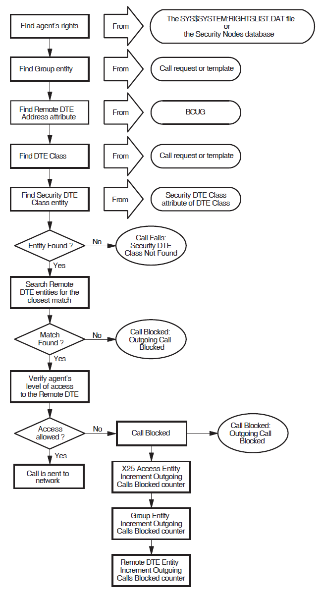
A.3. Verifying Incoming Calls
This section describes how X.25 Security verifies incoming calls. The description applies to X.25 Direct Connect, X.25 Client, and Connector systems. This section does not apply to incoming calls on a BCUG.
Figure A.3, ''How X.25 Security Verifies Incoming Calls'' shows the incoming call verification procedure.
The following sections explain the verification procedure.
A.3.1. Finding the Security DTE Class
The DTE entity carrying the incoming call has an Inbound DTE Class attribute.
X.25 Security finds the SECURITY DTE CLASS entity to use from the Security DTE Class characteristic of the DTE CLASS entity.
If the named SECURITY DTE CLASS entity does not exist, X.25 Security rejects the call and logs the Incoming Call Failed event, specifying the reason as "Security DTE Class Not Found".
A.3.2. Matching the Calling DTE Address Against Remote DTE Entities
X.25 Security obtains the sending DTE address from the call information. X.25 Security then matches the DTE address against the Remote Address Prefix attributes specified in the REMOTE DTE child entities of the chosen SECURITY DTE CLASS entity. Section 3.5, ''Remote DTE Entity Selection'' describes the matching algorithm.
A.3.3. Finding the Rights Identifiers for the Selected Remote DTE
The Rights Identifiers characteristic of the REMOTE DTE entity selected by the matching algorithm supplies the rights identifiers to associate with the incoming call.
A.3.4. Finding the Filter That Matches the Call
X25 Access matches a filter to the call. Matching a filter is described in the VSI X.25 for OpenVMS Management Guide.
A.3.5. Finding the Security Filter
X.25 Security finds the Security Filter to use from the Security Filter characteristic of the FILTER entity.
If the named SECURITY FILTER entity does not exist, the X25 Access module rejects the call and logs the Incoming Call Failed event specifying the reason as "Security Filter Not Found".
A.3.6. Verifying the Access Level to the Filter
X.25 Security matches the remote DTE’s rights identifiers (found in Section A.3.3, ''Finding the Rights Identifiers for the Selected Remote DTE'') against the ACL characteristic of the selected SECURITY FILTER entity. The access verification procedure is described in Section 3.6, ''The ACL Matching Procedure''.
If the access controls permit the level of access requested by the agent, the incoming call is passed to the listener for that filter at the local system.
A.3.7. What Happens if X.25 Security Blocks Access?
If the access controls specified in the selected SECURITY FILTER entity do not permit the remote DTE the level of access it requests, the X25 Access module clears the call. X.25 Security then:
Logs the Incoming Call Blocked event.
Increments the Incoming Calls Blocked counter on the X25 Access module.
Increments the Incoming Calls Blocked counter on the REMOTE DTE entity.
Increments the Incoming Calls Blocked counter on the FILTER entity.
Appendix B, "X.25 Security Events" describes X.25 Security events.
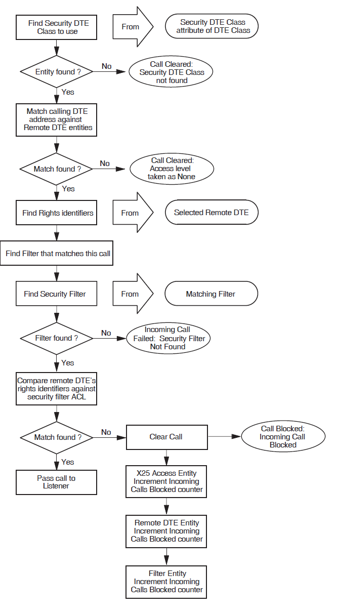
A.4. Verifying Incoming Calls Using Bilateral Closed User Groups
X.25 Security uses a different procedure to verify incoming calls that use BCUGs. The description in this section only applies to calls that specify a BCUG in the call packet.
Figure A.4, ''How X.25 Security Verifies Incoming Calls Using BCUGs'' illustrates the incoming call verification procedure.
A.4.1. Finding the Group Entity
The incoming call contains a group number. X.25 Security attempts to match the group number and calling DTE against the Members characteristic of each of the GROUP entities. X.25 Security selects a GROUP entity that contains the matching pair of values.
A.4.2. Finding the Rights Identifiers
X.25 Security uses the Members attribute of the GROUP entity to obtain the local X25 PROTOCOL DTE entity. This entity’s Inbound DTE Class attribute specifies the DTE CLASS entity to use. This entity’s Security Class DTE attribute specifies the SECURITY DTE CLASS to use. The Remote DTE Address attribute of the GROUP entity provides the DTE address to match against the Remote Address Prefix attributes specified in the REMOTE DTE child entities of the chosen SECURITY DTE CLASS entity. Section 3.5, ''Remote DTE Entity Selection'' describes the matching algorithm.
The Rights Identifiers characteristic of the REMOTE DTE entity selected by the matching algorithm supplies the rights identifiers to associate with the incoming call.
A.4.3. Subsequent Verification Procedure
The remainder of the call verification procedure is identical to that given in Section A.3.4, ''Finding the Filter That Matches the Call'' to Section A.3.6, ''Verifying the Access Level to the Filter''.
A.4.4. What Happens if X.25 Security Blocks Access?
If the access controls specified on the selected SECURITY FILTER entity do not permit the remote DTE the level of access it requests, the X25 Access module clears the call. X.25 Security:
Logs the Incoming Call Blocked event.
Increments the Incoming Calls Blocked counter on the GROUP entity.
Increments the Incoming Calls Blocked counter on the FILTER entity.
Increments the Incoming Calls Blocked counter on the X25 Access module.
Increments the Incoming Calls Blocked counter on the REMOTE DTE entity.
Appendix B, "X.25 Security Events" describes X.25 Security events.
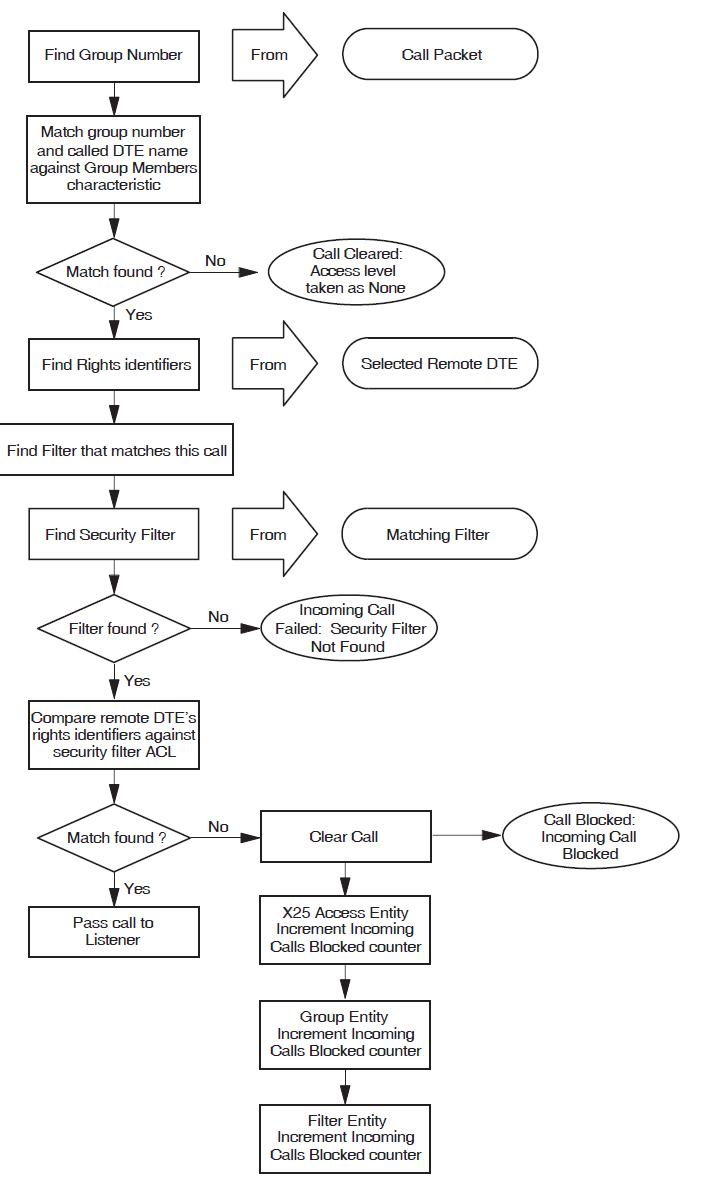
A.5. Verifying Access to Permanent Virtual Circuits
X.25 Security determines whether an application is authorized to connect to, and use, a PVC. This section describes how X.25 Security performs this verification. The description applies only to X.25 Direct Connect and Connector systems.
Figure A.5, ''How X.25 Security Verifies Access to PVCs'' shows the PVC verification procedure.
A.5.1. Finding Rights Identifiers
The rights identifiers are found using the methods described in Section A.1.1, ''Finding the Agent’s Rights Identifiers''.
A.5.2. Finding the PVC Entity
X.25 Security finds the PVC entity to use from the PVC access request.
A.5.3. Verifying the Access Level to the PVC
X.25 Security attempts to match the agent’s rights identifiers against the ACL characteristic of the selected PVC entity. The access level verification mechanism is described in Section 3.6, ''The ACL Matching Procedure''.
If the access controls permit the agent’s requested access level, X.25 Security allows the agent to use the PVC.
A.5.4. What Happens if X.25 Security Blocks Access?
PVC access fails if the access controls on the specified PVC entity do not allow the agent’s requested level of access. If this occurs, X.25 Security:
Logs the PVC Access Blocked event.
Increments the Accesses Blocked counter on the PVC entity.
Increments the PVC Accesses Blocked counter on the X25 Access module.
If X25 Server is the agent and PVC access fails at the Connector system, X.25 Security:
Logs the PVC Access Blocked event.
Increments the Accesses Blocked counter on the PVC entity.
Increments the PVC Accesses Blocked counter on the X25 Access module.
Increments the Outgoing Calls Blocked counter on the SECURITY NODES entity at the Connector system.
Logs the PVC Access Blocked event at the X.25 Client system, indicating that the block occurred at the Connector system.
For details of X.25 Security events, refer to Appendix B, "X.25 Security Events".
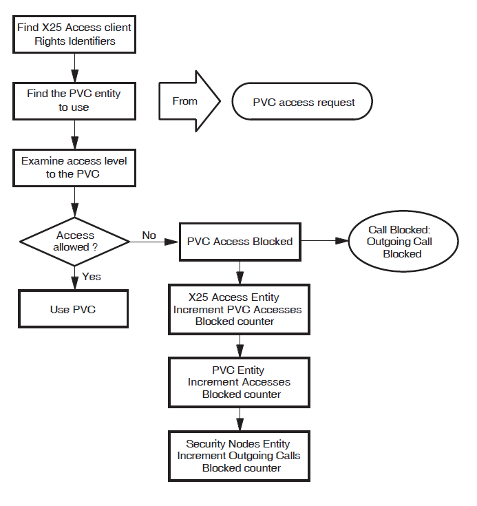
Appendix B. X.25 Security Events
This appendix describes the X25 Access module events that indicate call failures caused by X.25 Security. Each section:
Describes the event
Lists the security-related arguments that may be present
Lists the reasons that could have caused the event (where appropriate)
B.1. Incoming Call Failed
The Incoming Call Failed event indicates that an incoming call from the X25 Access module has failed. Table B.1, ''Incoming Call Failed - Arguments'' lists the arguments for this event.
| Argument | Description |
|---|---|
| Security DTE Class | The name of the SECURITY DTE CLASS entity that was referenced by the selected DTE CLASS entity. |
| Security Filter | The name of the SECURITY FILTER entity that was referenced by the selected FILTER entity. |
| Group | The name of the BCUG that matches the CUG number specified in the call packet. |
| Sending DTE | The DTE address of the calling DTE. This argument is only used when the incoming call is not delivered through a BCUG. |
Table B.2, ''Incoming Call Failed - Reasons'' lists the possible reasons for this event.
| Reason | Description | Action |
|---|---|---|
| Security Filter Not Found | The SECURITY FILTER entity named by the selected FILTER entity was not found. | Create the SECURITY FILTER entity or name another SECURITY FILTER entity in the FILTER entity. |
| Security DTE Class Not Found | The SECURITY DTE CLASS entity named by the selected DTE CLASS entity was not found. | Create the SECURITY DTE CLASS entity or name another SECURITY DTE CLASS entity in the DTE CLASS entity. |
B.2. Incoming Call Blocked
The Incoming Call Blocked event indicates that an incoming call from the X25 Protocol module (or X25 Client module in an X.25 Client system) was blocked (rejected) by the X25 Access module security mechanisms. Table B.3, ''Incoming Call Blocked - Arguments'' lists the arguments for this event.
| Argument | Description |
|---|---|
| Filter | The name of the X25 Access Filter that matched the call. |
| Inbound DTE Class | The DTE class name that the X25 Protocol module DTE entity associates with the incoming call. It identifies the SECURITY DTE CLASS entity to use for remote DTE matching. |
| Security DTE Class Remote DTE | The name of the SECURITY DTE CLASS REMOTE DTE entity whose remote address prefix was selected by the matching algorithm. This argument is only used when the incoming call is not delivered through a BCUG. |
| Sending DTE | The DTE address of the calling DTE. This argument is only used when the incoming call is not delivered through a BCUG. |
| Group | The name of the BCUG which matches the CUG number specified in the call packet. This argument is only used when the incoming call is delivered through a BCUG and will only be present at the Connector system as GROUP entities do not exist at the X.25 Client system. |
B.3. Outgoing Call Blocked
The Outgoing Call Blocked event indicates that the client of the X25 Access module is not allowed to make this call. Table B.4, ''Outgoing Call Blocked - Arguments'' lists the arguments for this event.
| Argument | Description |
|---|---|
| Client | The name of the entity that attempted to make the call. |
| Source | The name of the entity that performed the IO$ACCESS request. For X.25 Client systems, this argument identifies the client of X25 Access at the X.25 Client system when the call is blocked by security on the Connector system. |
| DTE Class | The DTE Class named in the call. This argument is used only when the call does not specify a BCUG. |
| Destination DTE | The called DTE address. |
| Security DTE Class Remote DTE | The name of the SECURITY DTE CLASS REMOTE DTE entity whose remote address prefix was selected by the matching algorithm. This argument is only used when the call does not specify a BCUG. |
| Blocked By | Identifies where the security block occurred (local security or Connector system security). If you are managing an X.25 Client system, this argument allows you to identify the system at which the problem occurred. |
| Group | The name of the BCUG specified in the call. This argument is only used when the call specifies a BCUG and will be present only at the Connector system as GROUP entities do not exist at the X.25 Client system. |
B.4. Outgoing Call Configuration Error
The Outgoing Call Configuration Error event indicates that a call failed due to incorrect configuration of the security databases. Table B.5, ''Outgoing Call Configuration Error - Arguments'' lists the argument for this event.
| Argument | Description |
|---|---|
| Security DTE Class | The name of the SECURITY DTE CLASS entity named by the selected DTE CLASS entity. This argument is present only when the reason for the event is Security DTE Class Not Found. |
Table B.6, ''Outgoing Call Configuration Error - Reasons'' lists the possible reasons for this event.
| Reason | Description | Action |
|---|---|---|
| Security DTE Class Not Found | The SECURITY DTE CLASS entity named by the selected DTE CLASS entity was not found. | Create the SECURITY DTE CLASS entity or name another SECURITY DTE CLASS entity in the DTE CLASS entity. |
B.5. PVC Access Blocked
The PVC Access Blocked event indicates that the client of the X25 Access module is not permitted to access this PVC. Table B.7, ''PVC Access Blocked - Arguments'' shows the arguments for this event.
| Argument | Description |
|---|---|
| Client | The name of the entity that tried to access the PVC. |
| Source | The name of the entity that tried to access the PVC. For X.25 Client systems, this argument identifies the client of X25 Access at the X.25 Client system when the call is blocked by security on the Connector system. |
| PVC | The name of the PVC. |
| Blocked By | Identifies where the security block occurred (X.25 Client system security or Connector system security). If you are managing an X.25 Client system, this argument allows you to identify the system at which the problem occurred. |
Appendix C. X.25 Security-Specific Identifiers
This appendix describes how X.25 Security handles system service requests using the rights identifiers PSI$X25_USER and PSI$DECLNAME.
In addition to the standard X.25 security entities, access to an X.25 for OpenVMS system is controlled by two rights identifiers:
PSI$X25_USER |
The rights identifier that you must grant to any user or process that is permitted to access X.25 for OpenVMS when a QIO IO$_ ACCESS system service is requested. |
PSI$DECLNAME |
The rights identifier that you must grant to any process that is permitted to declare itself a network process when a QIO IO$_ACPCONTROL system service is requested. |
These rights identifiers must be defined in the System Rights Database using the OpenVMS AUTHORIZE utility before the X.25 for OpenVMS software is loaded. If the identifiers are not defined before the software is loaded, but are defined subsequently, they have no effect and users require only NETMBX privilege to send calls via X.25 for OpenVMS.
When a user issues an IO$_ACCESS QIO, X.25 Security first determines whether the PSI$X25_USER identifier has been defined:
If PSI$X25_USER has been defined, X.25 Security determines whether the user is an owner of PSI$X25_USER -
If the user is an owner, the user is permitted to make the IO$_ACCESS system service call.
If the user is not an owner, X.25 Security determines whether the user has BYPASS privilege:
If the user has BYPASS privilege, the user is permitted to make the IO$_ACCESS system service call.
If the user does not have BYPASS privilege, the user is not permitted to make the IO$_ACCESS system service call.
If PSI$X25_USER has not been defined, X.25 Security determines whether the user has NETMBX privilege -
With NETMBX privilege, the user is permitted to make the IO$_ACCESS system service call.
Without NETMBX privilege, the user is not permitted to make the IO$_ACCESS system service call.
Note that a check for BYPASS privilege is made only if PSI$X25_USER is defined.
When a process requests an IO$_ACPCONTROL system service, X.25 Security first determines whether the PSI$DECLNAME identifier has been defined:
If PSI$DECLNAME has been defined, X.25 Security determines whether the process is an owner of PSI$DECLNAME -
If the process is an owner, it is permitted to make the IO$_ACPCONTROL system service call.
If the process is not an owner, X.25 Security determines whether the process has BYPASS privilege:
If the process has BYPASS privilege, it is permitted to make the IO$_ACPCONTROL system service call.
If the process does not have BYPASS privilege, it is not permitted to make the IO$_ACPCONTROL system service call.
If PSI$DECLNAME has not been defined, X.25 Security determines whether the process has NETMBX privilege -
With NETMBX privilege, the process is permitted to make the IO$_ACPCONTROL system service call.
Without NETMBX privilege, the process is not permitted to make the IO$_ACPCONTROL system service call.
Note that a check for BYPASS privilege is made only if PSI$DECLNAME is defined.