VSI X.25 for OpenVMS Programming Guide
- Software Version:
- VSI X.25 for OpenVMS Version 2.1
- Operating System and Version:
- VSI OpenVMS IA-64 Version 8.4-1H1 or higher
VSI OpenVMS Alpha Version 8.4-2L1 or higher
Preface
This manual describes how to write X.25 and X.29 programs to perform network operations.
The information in this manual applies to the X.25 functionality provided by VSI X.25 for OpenVMS and HP DECnet-Plus for OpenVMS VAX. Note that the X.25 functionality in DECnet-Plus for OpenVMS VAX was formerly provided by VAX P.S.I. software.
Throughout this manual, the X.25 functionality provided by both HP X.25 for OpenVMS and HP DECnet-Plus for OpenVMS VAX is referred to generically as X.25 for OpenVMS.
This manual uses the term Packet Switching Data Network (PSDN) to refer to any public or private packet switching network that X.25 for OpenVMS supports.
1. Audience
The manual assumes that you have knowledge and experience of:
The OpenVMS operating system
OpenVMS system services
Packet switching
DECnet-Plus
A programming language
The manual also assumes that you have a knowledge of general communications theory, and that you understand X.25 and PSDN terminology.
2. Structure
The manual is divided into six chapters and one appendix:
Chapter 1, "Introduction to X.25 and X.29 Communications", introduces you to X.25 and X.29 communications.
Chapter 2, "Introduction to X.25 and X.29 Programming", introduces X.25 and X.29 programming.
Chapter 3, "Using System Services to Handle Calls", describes how to use system services to handle X.25 and X.29 calls.
Chapter 4, "Writing an X.25 Program", describes how to write programs to handle X.25 calls.
Chapter 5, "Writing an X.29 Program", describes how to write programs to handle X.29 calls.
Chapter 6, "Setting Characteristics of the PAD, the NV Device, and the X.29 Terminal", describes how to handle the characteristics of the PAD, the X.29 terminal, and the NV device.
Appendix A, "Example of Parsing the Device Name String", provides an example program. Additional example programs are provided in
SYS$EXAMPLES:and described in the VSI X.25 for OpenVMS Programming Reference.
3. Associated Manuals
The following sections describe VSI DECnet-Plus for OpenVMS, VSI X.25 for OpenVMS, and VSI OpenVMS manuals that either directly describe the X.25 for OpenVMS software or provide related information.
VSI DECnet-Plus for OpenVMS Documentation
The following DECnet-Plus manuals contain information useful to X.25 for OpenVMS managers, users, and programmers:
VSI DECnet-Plus for OpenVMS Introduction and User’s Guide
This manual provides general information on DECnet-Plus and describes the concept of packet switching data networks.
VSI DECnet-Plus for OpenVMS Installation and Configuration
This manual describes how to install and configure DECnet-Plus for OpenVMS software. For OpenVMS IA-64 and OpenVMS Alpha systems, this manual also describes how to install X.25 for OpenVMS software. Details on configuring X.25 for OpenVMS on OpenVMS IA-64 and OpenVMS Alpha systems are provided in the VSI X.25 for OpenVMS Configuration Guide. For OpenVMS VAX systems, this manual also describes how to install and configure the X.25 functionality provided by DECnet-Plus for OpenVMS VAX.
VSI DECnet-Plus for OpenVMS Network Management
This manual provides conceptual and task information about managing and monitoring a DECnet-Plus network. In addition, the manual devotes a section to the management of X.25 entities used by DECnet operating over X.25 data links.
VSI DECnet-Plus for OpenVMS Network Control Language Reference
This manual provides detailed information on the Network Control Language (NCL), which is used to manage X.25 for OpenVMS management entities.
VSI X.25 for OpenVMS Documentation
The following manuals make up the X.25 for OpenVMS documentation set:
VSI X.25 for OpenVMS Configuration Guide (OpenVMS IA-64 and OpenVMS Alpha)
This manual explains how to configure X.25 for OpenVMS software on OpenVMS IA-64 and OpenVMS Alpha systems.
VSI X.25 for OpenVMS Security Guide
This manual describes the X.25 Security model and how to set up, manage, and monitor X.25 Security to protect your X.25 for OpenVMS system from unauthorized incoming and outgoing calls.
VSI X.25 for OpenVMS Problem Solving Guide
This manual provides guidance on how to analyze and correct X.25-related and X.29-related problems that may occur while using the X.25 for OpenVMS software. In addition, the manual describes loopback testing for LAPB data links.
VSI X.25 for OpenVMS Programming Reference
This manual provides reference information for X.25 and X.29 programmers. It is a companion manual to this manual.
VSI X.25 for OpenVMS Utilities Guide
This manual describes how to use and manage X.25 Mail and how to use and manage a host-based PAD to connect to a remote system. It also describes how to manage the X.29 communication links used for both of these functions. In addition, this manual explains how to use OpenVMS DCL
SET
                            TERMINAL/X29
commands to manage remote host-based or network PADs.VSI X.25 for OpenVMS Accounting Guide
This manual describes how to use X.25 Accounting to obtain performance records and information on how X.25 is being used on your system.
VSI OpenVMS Documentation
The following OpenVMS manuals contain information useful to X.25 for OpenVMS managers, users, and programmers:
4. VSI Encourages Your Comments
You may send comments or suggestions regarding this manual or any VSI document by sending electronic mail to the following Internet address: <docinfo@vmssoftware.com>. Users who have VSI OpenVMS support contracts through VSI can contact <support@vmssoftware.com> for help with this product.
5. OpenVMS Documentation
The full VSI OpenVMS documentation set can be found on the VMS Software Documentation webpage at https://docs.vmssoftware.com.
6. Terminology
The terminology used in the VAX P.S.I. product has been replaced by the terminology used in the X.25 for OpenVMS product. Table 1, ''X.25 Terminology'' shows the correlation between VAX P.S.I. terms and their X.25 for OpenVMS counterparts.
| VAX P.S.I. | X 25 for OpenVMS VAX |
|---|---|
| Access system | X.25 Client system |
| Native system | X.25 Direct Connect system |
| Multihost system | X.25 Connector system |
| Gateway system X.25 | X.25 Connector system |
In addition to the terms shown in Table 1, ''X.25 Terminology'', the X.25 for OpenVMS documentation set uses the following standard terms for client systems, server systems, relay systems, and the X.25 for OpenVMS management entities that represent these systems:
| Client System | A client system of an X.25 Connector system (and therefore a client of the X25 Server management module on the X.25 Connector system.) |
| Relay Client system | A client system of an X.25 Relay system (and therefore a client of the X25 Relay management module on the X.25 Relay system.) |
| Relay-Client | A shorthand term for an X25 RELAY CLIENT management entity on an X.25 Relay system that contains management information about an actual Relay Client system. |
| Relay system | An X.25 Direct Connect or Connector system with the X.25 Relay module enabled. |
| Server Client system | Another term for a Client system. |
| Server-Client | A shorthand term for an X25 SERVER CLIENT management entity on an X.25 Connector system that contains management information about one or more actual X.25 Client systems. |
For more information about clients, servers, and relays in X.25 for OpenVMS, refer to the VSI X.25 for OpenVMS Configuration Guide and the VSI X.25 for OpenVMS Management Guide.
7. Conventions
The following conventions are used in the X.25 for OpenVMS documentation set:
| UPPERCASE and lowercase |
The OpenVMS operating system does not differentiate between lowercase and uppercase characters. Literal strings that appear in text, examples, syntax descriptions, and function descriptions can be entered using uppercase characters, lowercase characters, or a combination of both. In running text, uppercase characters indicate OpenVMS DCL commands and command qualifiers; Network Control Language (NCL) commands and command parameters; other product-specific commands and command parameters; network management entities; OpenVMS system logical names; and OpenVMS system service calls, parameters, and item codes. Leading uppercase characters, such as Protocol State, indicate management entity characteristics and management entity event names. Leading uppercase characters are also used for the top-level management entities known as modules. |
system output | This typeface is used in interactive and code examples to indicate system output. In running text, this typeface is used to indicate the exact name of a device, directory, or file; the name of an instance of a network management entity; or an example value assigned to a DCL qualifier or NCL command parameter. |
user input | In interactive examples, user input is shown in
bold print. |
| $ | In this manual, a dollar sign ($) is used to represent the default OpenVMS user prompt. |
| Ctrl/X | In procedures, a sequence such as Ctrl/X indicates that you must hold down the key labeled Ctrl while you press another key or a pointing device button. |
| Return | In procedures, a key name is shown enclosed to indicate that you press the corresponding key on the keyboard. |
| italic text | Italic text indicates variables or book names. Variables include information that varies in system input and output. In discussions of event messages, italic text indicates a possible value of an event argument. Italic text also indicates an important term, or important information. |
| ( ) | In a command definition, parenthesis indicate that you must enclose the options in parenthesis if you choose more than one. Separate the options using commas. |
| { } | In a command definition, braces are used to enclose sets of values. The braces are a required part of the command syntax. |
| [ ] | In a command definition, square brackets are used to enclose parts of the command that are optional. You can choose one, none, or all of the options. The brackets are not part of the command syntax. However, brackets are a required syntax element when specifying a directory name in an OpenVMS file specification. |
Note
The following conventions apply to multiplatform documentation.
|
IA-64/Alpha OpenVMS | Indicates information specific to OpenVMS IA-64 and OpenVMS Alpha. Note that single lines of information specific to OpenVMS IA-64 and OpenVMS Alpha are marked "(OpenVMS IA-64 and OpenVMS Alpha)" or "(OpenVMS IA-64/Alpha)". |
|
OpenVMS VAX | Indicates information specific to OpenVMS VAX. Note that single lines of information specific to OpenVMS VAX are marked "(OpenVMS VAX)". |
| ◆ | Indicates information specific to OpenVMS VAX. Note that single lines of information specific to OpenVMS VAX are marked "(OpenVMS VAX)". |
Chapter 1. Introduction to X.25 and X.29 Communications
1.1. Communicating Over a PSDN
VSI X.25 for OpenVMS allows a local DTE to use a remote DTE as though the user were directly connected to it.
The kind of program you write to achieve this depends on the remote DTE:
To communicate with a packet-mode DTE, you write an X.25 program.
To communicate with a character-mode DTE, you write an X.29 program.
To communicate with a Packet Assembler/Disassembler (PAD), you write an X.29 program.
1.2. X.25 Communications and X.29 Communications
This section introduces the components of an X.25 and an X.29 communications link.
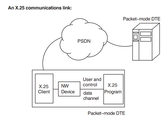
Figure 1.1, ''X.25 and X.29 Communication Links'' shows the components in an X.25 and an X.29 communications link.
The CCITT (Comité Consultatif International Télégraphique et Téléphonique) has established recommendations which define the interfaces between the standard components of a communications link across a PSDN. For details of these recommendations, refer to the VSI DECnet-Plus for OpenVMS Introduction and User’s Guide.
1.2.1. NW Device
In X.25 communications, the NW device (or X.25 network device, or NWA0:) processes control data and user data which passes between the X.25 program and X.25 for OpenVMS.
In X.29 communications, the NW device processes system services relating to network control, which are issued by the X.29 program, and passes them to the NV device.
1.2.2. NV Device
The NV device is used in X.29 communications to handle data transfer across an X.25 network. The NV device uses the X.29 protocol which connects the user’s X.29 program to the PAD.
1.2.3. TT Device
The TT device processes system services relating to user data, which are issued by the X.29 program, and passes them to the NV device. The OpenVMS terminal driver controls the TT device.
For descriptions of the other components in the X.25 and X.29 communications links, refer to the VSI DECnet-Plus for OpenVMS Introduction and User’s Guide.
The differences between X.25 communications and X.29 communications are described in Table 1.1, ''Facilities Offered by X.25 and X.29 Programming''
| X.25 Communications | X.29 Communications |
|---|---|
| In an X.25 physical link, the remote terminal is a packet-mode DTE which connects directly to the PSDN. | In an X.29 physical link, the remote X.29 terminal connects to the PSDN through a PAD. |
| In X.25 communications, both control data and user data pass between the X.25 program and X.25 for OpenVMS through an NW device. |
In X.29 communications, user data passes between the X.29 program and X.25 for OpenVMS through an NV device, and control data passes between the X.29 program and X.25 for OpenVMS through an NW device. The reasons for this are:
|
|
X.25 programming offers the user program the full range of X.25 facilities and features offered by X.25 for OpenVMS. Major facilities offered:
Host-to-host communications require X.25 programs. |
X.29 programming offers the user program a subset of X.25 features through the NV device, plus X.29-specific facilities. Major facilities offered:
Terminal-to-host communications require X.29 programs. Data channels through an NV device to an X.29 terminal requires TT device programs. |
Section 1.3, ''Interaction of the NV Device, the PAD, and the X.29 Terminal'' provides some details of how the X.29 communications link works.
1.3. Interaction of the NV Device, the PAD, and the X.29 Terminal
Figure 1.2, ''Action of the NV Device with the PAD and the X.29 Terminal'' illustrates the actions the NV device takes in response to actions from and changes in the characteristics of the PAD and the X.29 terminal.
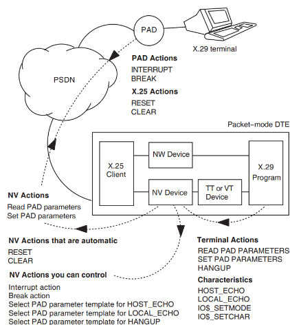
Figure 1.2, ''Action of the NV Device with the PAD and the X.29 Terminal'' shows how data is transferred between the PAD and the NV device and between the NV device and the TT device.
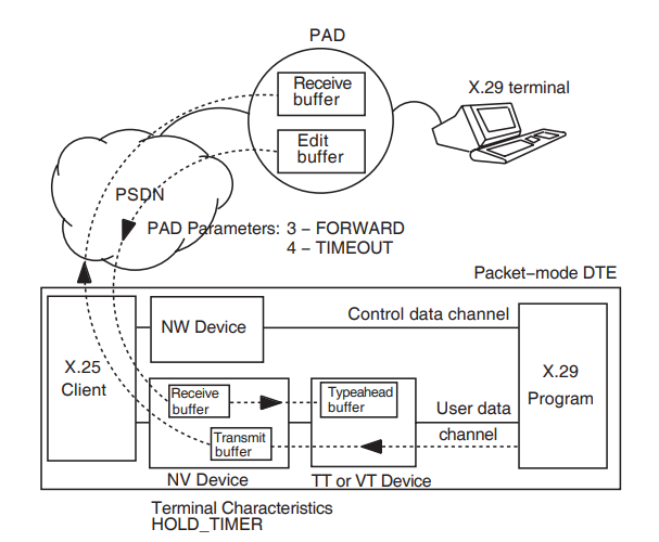
1.3.1. Transfer of Data from the PAD to the TT Device
The PAD transfers data from the X.29 terminal to the TT device as follows:
Characters of data typed in by the user arrive at the PAD and are stored in the PAD’s edit buffer.
The characters stay in the PAD’s edit buffer until one of the following criteria is met:
The edit buffer is full.
The PAD receives a forwarding character from the X.29 terminal.
Forwarding characters are determined by the PAD forwarding characteristic.
The time since the first character arrived exceeds a timeout period, determined by the timeout characteristic of the PAD.
The user of the X.29 terminal removes the characters from the buffer, for example, by pressing the delete key.
The PAD then forms a packet of the characters in the edit buffer, and sends the packet to the NV device over the PSDN.
The packets arriving at the NV device are stored in the receive buffer of the NV device, where they are disassembled.
The characters in the receive buffer of the NV device are sent to the TT device, where they go into the TT typeahead buffer.
The characters in the typeahead buffer are sent to the user program when a Read QIO is issued.
1.3.2. Transfer of Data from the TT Device to the PAD
The TT device transfers data to the PAD as follows:
The TT device sends characters to the NV device, where they are stored in a transmit buffer.
The characters stay in the transmit buffer until one of the following criteria is met:
The transmit buffer is full.
No more data is available from the TT device, and the Hold Timer = 0.
No more data is available from the TT device, and the Hold Timer expires.
The NV device forms a packet of the characters in the transmit buffer, and sends the packet to the PAD.
Chapter 2. Introduction to X.25 and X.29 Programming
This chapter gives general guidance on:
Establishing a virtual circuit (refer to Section 2.1, ''Establishing a Virtual Circuit'')
Using the X.25 library? (refer to Section 2.2, ''Using the X.25 Library'').
The use of system services in communications (refer to Section 2.3, ''Using System Services'').
The use of data structures (refer to Section 2.4, ''Data Structures'').
Coding in MACRO and in high-level languages (refer to Section 2.5, ''MACRO Coding'' and Section 2.6, ''High-level Language Coding'').
The system resources you need to make outgoing calls and accept incoming calls (refer to Section 2.7, ''System Resources Required for a Virtual Circuit'').
2.1. Establishing a Virtual Circuit
To pass messages across a PSDN, your program must first establish a virtual circuit to a remote DTE. For incoming calls, you do this by accepting an incoming call request. For outgoing calls, you send a request to connect to the remote DTE.
Note that for communications with an X.29 terminal you can only use a Switched Virtual Circuit (SVC). An SVC is a virtual circuit that is established temporarily for the duration of a call. You cannot use a Permanent Virtual Circuit (PVC).
When your program has established a virtual circuit, it can use the virtual circuit to send and receive messages, and to issue control and synchronization requests to the X.29 terminal.
2.2. Using the X.25 Library
You must include the X.25 library in every program you write for X.25 for OpenVMS.
How you include the X.25 library depends on the language you are using:
For MACRO, use the following command:
.LIBRARY "SYS$LIBRARY:PSILIB"
Declare the symbols specific to X.25 for OpenVMS by specifying the following symbol in the program:
$PSIDEF
For most of the major languages, include the source file which contains definitions.
The languages for which this applies, and their source files are:
FORTRAN PSILIB.FOR C PSILIB.H PASCAL PSILIB.PAS BLISS32 PSILIB.R32 (this is used to build PSILIB.L32) MACRO PSILIB.MLB ADA PSILIB.ADA For any other language, create your own definition file in one of the following ways:
Use the definition file for another language to create your own definition file.
For a high-level language, write a MACRO module including the following:
.LIBRARY "SYS$LIBRARY:PSILIB"
$PSIDEF <==>,<::>
Assemble this file and link the resulting object file with your program.
2.3. Using System Services
X.25 for OpenVMS programs use OpenVMS system services to communicate over a PSDN. Your program uses the system services to:
Assign and deassign channels logically connecting you to the PSDN (or to another machine in the case of a point-to-point link).
Specify which calls your process will handle.
Set up and clear the virtual circuits that carry your data over the PSDN.
Send and receive data.
Issue control and synchronization requests.
Each programming language supported by OpenVMS has a mechanism for calling system services. See the relevant programming language user guide for details.
For further details of using the system services, refer to Chapter 3, "Using System Services to Handle Calls".
2.4. Data Structures
This section introduces the data structures that you use for X.25 and X.29 programming:
The Network Connect Block (NCB)-This is described in Section 2.4.1, ''The Network Connect Block (NCB)''
The Mailbox-This is described in Section 2.4.2, ''The Mailbox''
2.4.1. The Network Connect Block (NCB)
The Network Connect Block (NCB) is a user-generated data structure composed of a number of variable-length items. Each item consists of a Length field, a Type Code field, and a variable-length Data field. The Type Code field identifies the item. For details of the NCB structure and item types, and a summary of the mandatory and optional fields in the NCB, refer to the VSI X.25 for OpenVMS Programming Reference manual; that manual also contains an example of an NCB.
The Network Connect Block is used by:
Your program to pass information about outgoing calls to X.25 for OpenVMS.
X.25 for OpenVMS to pass information about incoming calls to your program.
X.25 for OpenVMS to pass information about call clears and call confirmations to your program.
The NCB is used to set up, accept, redirect, reject, and clear virtual circuits.
2.4.1.1. How to Set Up a Network Connect Block
Type codes are used to specify information in the Network Connect Block. The type codes that can be used depend on the $QIO system service requested. Some type codes are mandatory, others are optional.
Full details of the type codes associated with each $QIO system service are given in the VSI X.25 for OpenVMS Programming Reference manual.
Note that:
For outgoing calls, the most convenient way to specify information about the call is to use the type code PSI$C_NCB_TEMPLATE to specify the name of the template you want to use. Provided that the template has been defined correctly, you need only specify the name of the template to provide the information for the call.
If you are a member of a Bilateral Closed User Group, no remote DTE address is required.
2.4.2. The Mailbox
X.25 for OpenVMS uses a mailbox to pass NCB information to a program. The NCB:
Contains the information you need to know about an incoming call.
Informs you of network events (for example, when a call has been cleared).
It is advisable to associate a mailbox with each NW or NV device you use to accept or make a call. If you do not, you will receive only indirect notification of network events.
Use the $CREMBX system service to create a mailbox before you assign a channel to your network device with the $ASSIGN system service.
Section 3.1.1, ''Creating a Mailbox'' describes how to create a mailbox.
For detailed information about the mailbox, refer to the VSI X.25 for OpenVMS Programming Reference manual, where the mailbox structure and mailbox message types are described.
2.5. MACRO Coding
System service macros generate argument lists and CALL instructions to call system services. These macros are located in the system library SYS$LIBRARY:STARLET.MLB. This library is searched automatically for unresolved references when you assemble a source program. Symbols and macro definitions specific to X.25 for OpenVMS are contained in the library SYS$LIBRARY:PSILIB.MB. Always include this library in any MACRO application programs that you write, and declare any symbols specific to X.25 for OpenVMS, as described in Chapter 4, "Writing an X.25 Program" and Chapter 5, "Writing an X.29 Program".
You need to know the MACRO rules for assembly-language coding to be able to understand the material presented in this section. Full details of the rules are provided in the VAX MACRO and Instruction Set Reference Manual.
2.5.1. Argument Lists
The arguments required by a system service are shown in the system service descriptions in the VSI X.25 for OpenVMS Programming Reference manual. The Macro Format for each system service shows the positional dependencies and keyword names of each argument.
All arguments are longwords. The first longword in the list must contain, in its low-order byte, the number of arguments in the remainder of the list. The remaining three bytes must be zeros.
If you omit an optional argument in a system service macro instruction, the macro supplies a default value for the argument.
For details of the generic macro forms used for coding calls to system services, refer to the MACRO documentation.
2.6. High-level Language Coding
Each high-level language supported by OpenVMS provides a mechanism for calling an external procedure and passing arguments to that procedure. However, the type of mechanism and the terminology used vary from one language to another.
OpenVMS system services are external procedures that accept arguments. There are three ways to pass arguments to system services:
By value. The argument is the actual value to be passed (a number or a symbolic representation of a numeric value).
By reference. The argument is the address of an area or field that contains the value. An argument passed by reference is usually expressed as a label associated with an area or field. (In fact, one common error is to pass a numeric value without indicating that it is passed by value. If the compiler assumes the numeric value is an address, a run–time access violation error may occur when, for example, the image tries to access virtual address 0 or 1.)
By descriptor. This argument is also an address, but of a special data structure called a character string descriptor. Descriptors are explained fully in the VSI OpenVMS Record Management Services Reference Manual.
2.7. System Resources Required for a Virtual Circuit
To set up a virtual circuit requires certain system resources, which are deducted from the quota for your process.
The quota allocation is the same for both SVCs and PVCs.
A virtual circuit counts as an open file for quota purposes. Therefore, for each virtual circuit you set up your FILLM quota for open files decreases by one.
A certain amount of buffered I/O byte count (BYTLM) quota is also deducted. This space is used to buffer receive data that has not yet been requested by your application program. The default amount taken is the smaller of:
(packet-size + 276) * 7
or
(packet-size + 276) * window-size
You can request a different value for this quota (in bytes) by using the PSI$C_ NCB_RCV_QUOTA NCB item. The minimum value is:
(packet-size + 276)
The maximum value is:
(packet-size + 276) * window-size
If you exceed this quota, X.25 for OpenVMS tells the PSDN that it is unable to receive more data. This can cause your application to run slowly.
Chapter 3. Using System Services to Handle Calls
This chapter introduces the system services you can use to handle X.25 and X.29 calls, and describes how to use them.
This chapter describes how to use system services to:
Set up and clear communications
Handle incoming calls
Send and receive data
In X.29 programs, you can use system services to handle PAD and NV characteristics. For details of how to do this, refer to Chapter 6, "Setting Characteristics of the PAD, the NV Device, and the X.29 Terminal".
The system services and their uses are shown in Table 3.1, ''System Services'' and Table 3.2, ''Function Codes for the $QIO System Services''.
| Call | Use |
|---|---|
| $ASSIGN | Assign a channel. |
| $GETDVI |
One of the following:
|
| $CREMBX | Create a mailbox. |
| $DASSGN | Deassign a channel. |
| $QIO, $QIOW | Set up a virtual circuit and transfer data. See Table 3.2, ''Function Codes for the $QIO System Services'' for supported function codes. |
When you have associated a channel with a device, you use the $QIO (Queue I/O Request) or $QIOW (Queue I/O Request and Wait) system service to:
Specify which calls your process will handle.
Set up and clear the virtual circuit.
Send and receive data messages.
Issue control and synchronization requests over the virtual circuit.
Handle PAD, NV, and terminal characteristics (X.29 programs only).
The $QIO service and the $QIOW service are identical in every way, except that:
$QIO completes asynchronously; that is, it returns to your program immediately after queuing the I/O request. It does not wait for the operation to complete.
$QIOW completes synchronously; that is, it waits until the operation has completed before returning to your program.
Throughout this manual and the VSI X.25 for OpenVMS Programming Reference manual, the term $QIO is used to mean either $QIO or $QIOW.
For further information about $QIO and $QIOW services, refer to the OpenVMS system services documentation.
You tell the $QIO to perform a particular function, by means of function codes. The function codes relevant to X.25 and X.29 communications are listed in Table 3.2, ''Function Codes for the $QIO System Services''.
| Function | Use |
|---|---|
| IO$_ACCESS | Set up a virtual circuit. |
| IO$_DEACCESS | Clear a virtual circuit. |
| IO$_ACCESS!IO$M_ACCEPT | Accept a request to set up a virtual circuit. |
| IO$_ACCESS!IO$M_REDIRECT | Redirect a request to set up a virtual circuit. |
| IO$_ACCESS!IO$M_ABORT | Reject a request to set up a virtual circuit. |
| IO$_ACPCONTROL | Declare a network process. |
| IO$_NETCONTROL |
|
| IO$_WRITEVBLK | Transmit data. |
| IO$_READVBLK | Receive data. |
| IO$_NETCONTROL, PSI$K_X29_READ | Read PAD parameters or NV terminal |
| IO$_NETCONTROL, PSI$K_X29_READ_ SPECIFIC | Read specific PAD parameters or NV terminal characteristics. |
| IO$_NETCONTROL, PSI$K_X29_SET | Set specific PAD parameters or NV terminal characteristics. |
In addition, the functions supported by the terminal driver are available at the $QIO interface. For details of the terminal driver $QIOs, refer to the OpenVMS terminal driver documentation.
3.1. Setting up and Clearing Communications
This section describes how to set up and clear communications for X.25 and X.29 programming. It describes how to:
Create a mailbox – refer to Section 3.1.1, ''Creating a Mailbox''.
Assign the control and data channels – refer to Section 3.1.2, ''Assigning the Control and Data Channels''.
Connect the NV device to the OpenVMS terminal driver as a virtual terminal – refer to Section 3.1.3, ''Connection as a Virtual Terminal (VT)''.
Request a virtual circuit – refer to Section 3.1.4, ''Requesting a Virtual Circuit''.
Clear a call – refer to Section 3.1.5, ''Clearing a Call''.
3.1.1. Creating a Mailbox
If your program is to handle incoming calls, you must use a mailbox to receive notification of their arrival. You can then use the specified mailbox to receive messages of network events and interrupts.
If your program makes outgoing calls only, and you do not want direct notification of network events, you need not create a mailbox. Note, however, that without a mailbox you cannot receive interrupts.
There are two ways to create a mailbox:
Use the $CREMBX system service. Use the $ASSIGN call to associate the mailbox with the NW or NV device you use to make or accept the call. The mailbox remains associated with the NW or NV device until you either delete the mailbox, or deassign the channel.
Use a run-time library routine, LIB$ASN_WTH_MBX. This routine:
Creates a temporary mailbox.
Assigns a channel to the mailbox.
Assigns a channel to the NW or NV device.
This routine creates a unique mailbox every time it is called. For a complete description of this routine, refer to the OpenVMS documentation of run-time library routines.
For a description of the mailbox structure and message types, refer to the VSI X.25 for OpenVMS Programming Reference manual.
3.1.2. Assigning the Control and Data Channels
There are two ways to assign a channel to a device and associate a mailbox with it:
Use $ASSIGN to obtain a channel and associate a mailbox with it.
For an X.25 program, explicitly assign a channel to the device NWA0:. The X.25 for OpenVMS software creates a new device called NWAuu:, where uu is a unique unit number, and assigns the channel to that device. $ASSIGN does not assign a channel to NWA0:.
Always assign one such channel for each virtual circuit and never explicitly assign another channel to the NWAuu that is in use for other operations.
If your program creates a mailbox, use the run-time library routine LIB$ASN_WTH_MBX to create a mailbox, and assign a channel to the NW or NV device, as described in Section 3.1.1, ''Creating a Mailbox''
To find the unit number, uu, of the NW device, issue $GETDVI on the same channel.
3.1.3. Connection as a Virtual Terminal (VT)
If the NV device is connected to the OpenVMS terminal driver as a VT (virtual terminal) device, your program must use a special procedure to calculate the unit number of the NV device.
If there is a VT device associated with the NV terminal, the $GETDVI system service call returns information about the VT device. In particular, DVI$_UNIT returns the unit number of the VT device, not the unit number of the NV device.
To obtain the unit number of the NV device:
Issue $GETDVI with the item code DVI$_TT_PHYDEVNAM to obtain the physical device name of the terminal.
Determine the unit number of the NV device by parsing the device name string that $GETDVI returns.
For an example of how to parse a device name string to extract the device unit number, refer to Appendix A, "Example of Parsing the Device Name String".
3.1.4. Requesting a Virtual Circuit
Use $QIO(IO$_ACCESS) to set up a virtual circuit to a remote DTE, and optionally request network facilities. If you subscribe to the fast select facility, you can use this call to send 128 instead of 16 bytes of user data.
Also use this call before transmitting or receiving data on a Permanent Virtual Circuit (PVC). For a PVC, specify the name of the PVC in the NCB.
You must supply an NCB to inform X.25 for OpenVMS how you want the virtual circuit to be set up. For details of how to set up an NCB, refer to Section 2.4.1.1, ''How to Set Up a Network Connect Block''.
Note that you must always specify the length of the NCB in the descriptor.
Certain system resources are used to set up a virtual circuit. For details of the system resources you require to set up virtual circuits, refer to Section 2.7, ''System Resources Required for a Virtual Circuit''.
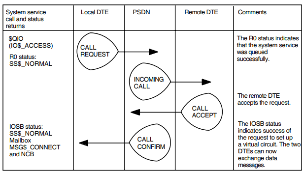
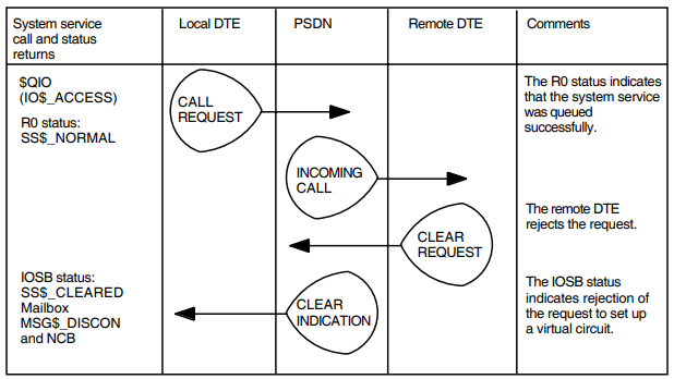
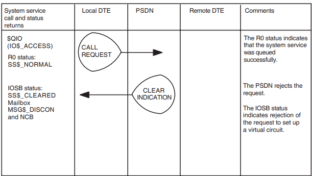
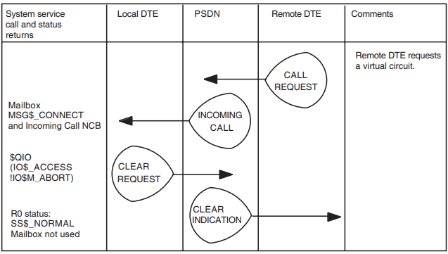
Figure 3.1, ''Set Up a Virtual Circuit-Call Accepted'', Figure 3.2, ''Set Up a Virtual Circuit - Call Rejected by Remote DTE'', and Figure 3.3, ''Set Up a Virtual Circuit -Call Rejected by Network'' show the request for a virtual circuit being accepted, being rejected by the remote DTE, and being rejected by the network.
3.1.5. Clearing a Call
You can clear a call in either of the following ways:
Use the $DASSGN call to deassign the channel and immediately terminate all communication.
Issue the $DASSGN call only after all communication between DTEs over that channel is complete. The call releases the channel, disassociates the mailbox from the channel, and terminates communication immediately.
Use the $QIO(IO$_DEACCESS) operation to clear a virtual circuit. Also use this operation when you have finished transmitting or receiving data over a PVC.
Clearing a virtual circuit uses NCBs only for diagnostic codes and local facilities. Use the diagnostic code field (PSI$C_NCB_DIAGCODE) of the NCB to contain user-specified codes that show reasons for clearing the virtual circuit. You can also specify or modify local facilities by adding a local facilities field (PSI$C_NCB_LOCFAC) to the NCB.
Note that clearing a virtual circuit can result in loss of data in either direction. Clear a virtual circuit only when you know that the remote DTE has received all your data, or you have received all the data from the remote DTE. It is advisable, therefore, to have a method of confirming receipt of data before clearing a virtual circuit.
If you are transferring data in a single direction only (for example, a file transfer), terminate the transfer using a shutdown message recognized by both ends. You can use the qualified data subchannel for this purpose. On receipt of the shutdown termination message, the circuit can be cleared.
If you are transferring data in both directions, use two termination messages. When one application (the requestor) wants to terminate the call, it sends the other application (the responder) a shutdown message after transmitting all of its data. When the responder receives this shutdown message, it can complete its data transfer, then return a message to the requestor indicating that the shutdown can be performed. On receiving the message, the requestor can then clear the call.
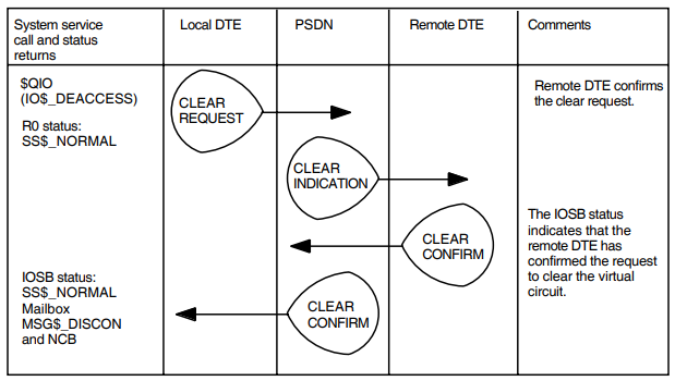
Figure 3.4, ''Clear a Virtual Circuit''shows how a virtual circuit is cleared.
3.2. Handle Incoming Calls
This section describes how to:
Define a network process, and specify which incoming calls your process will handle – refer to Section 3.2.1, ''Defining a Network Process and Specifying Which Incoming Calls Your Process Will Handle''.
Assign a channel to receive data – refer to Section 3.2.2, ''Assigning a Channel for Receiving Data''.
Accept an incoming X.25 call request – refer to Section 3.2.3, ''Accepting an Incoming X.25 Call Request''.
Reject an incoming X.25 call request – refer to Section 3.2.4, ''Rejecting an Incoming X.25 Call Request''.
Redirect an incoming X.25 call request – refer to Section 3.2.5, ''Redirecting an Incoming X.25 Call Request''.
3.2.1. Defining a Network Process and Specifying Which Incoming Calls Your Process Will Handle
X.25 and X.29 programs can issue $QIO(IO$_ACPCONTROL) calls to declare themselves as network processes. Each $QIO(IO$_ACPCONTROL) call specifies a filter to be used in determining which incoming calls the process will handle.
The filter specified in a $QIO(IO$_ACPCONTROL) call can be one of two types:
Static
This type of filter is one that is created using management commends. It is available until either disabled or deleted.
Dynamic
This type of filter is created dynamically by defining its characteristics in the $QIO(IO$_ACPCONTROL) call. A filter created in this way ceases to exist when the specified channel is deassigned.
The IO$_ACPCONTROL call defines a number of other parameters to identify the incoming calls that the process will handle. Some of these parameters are the template, local subaddress, the remote DTE address, the user data field, and user group identification. A full list of parameters is provided in the VSI X.25 for OpenVMS Programming Reference manual.
When it has matched the parameters of an incoming call with those of a network process, X.25 for OpenVMS puts the NCB for the incoming call in the mailbox associated with the channel over which the IO$_ACPCONTROL was issued.
Your process can then accept, reject, or redirect the incoming call.
If you want the process to handle calls that match another combination of parameters, have the process issue another $QIO(IO$_ACPCONTROL).
The parameters used to identify acceptable incoming calls are contained in a Network Process Declaration Block (NPDB). This block consists of a string of variable length items. Each item has a two-word header giving its length (in bytes) and its type. The type codes, their description, and use are given in the VSI X.25 for OpenVMS Programming Reference manual.
3.2.2. Assigning a Channel for Receiving Data
To receive incoming calls, you first have to assign a channel (as with transmitting a call). Use the $ASSIGN system service to obtain a channel and to associate a mailbox with this channel.
For further details about this system service, refer to Section 3.1.2, ''Assigning the Control and Data Channels''.
3.2.3. Accepting an Incoming X.25 Call Request
Use $QIO(IO$_ACCESS!IO$M_ACCEPT) to accept an incoming request to set up a virtual circuit. This $QIO call also allows you to negotiate facilities requested by the incoming call. If you subscribe to the fast select acceptance facility with no restriction on response, you can also use $QIO(IO$_ACCESS!IO$M_ACCEPT) to send user data.
You are advised to use the NCB received in the incoming call as an argument to this $QIO. Issue $QIO(IO$_READVBLK) to read the NCB from the mailbox associated with the control channel to NWAuu:. If you create a new NCB to accept the call, the new NCB must contain the incoming call identification field (PSI$C_NCB_ICI) from the mailbox’s NCB to associate the channel with the received call.
If the incoming call specifies fast select with no restriction on response and you wish to reply with user data, add a response data field (PSI$C_NCB_RESPDATA) to the NCB. Accepting the call changes it to a normal call request, and your program can read and transmit messages as usual.
You can modify the following items in the NCB and hence negotiate the associated facilities:
Throughput class (PSI$C_NCB_THRUCLS)
Packet size selection (PSI$C_NCB_PKTSIZE)
Window size selection (PSI$C_NCB_WINSIZE)
Expedited data negotiation (PSI$C_NCB_EXPEDITE)
Called address extension (PSI$C_NCB_CALLED_EXTENSION)
Local facilities (PSI$C_NCB_LOCFACR)
The items to be negotiated can either be specified individually in the NCB or collectively in a template using the PSI$C_NCB_TEMPLATE item code. Note that if the PSI$C_NCB_TEMPLATE item code is not specified, the template Default is used.
A template can also be used to specify parameters that are not defined in the NCB used to accept the call. In addition to the negotiated items, the following items can be added to the NCB:
Template (PSI$C_NCB_TEMPLATE)
Network user identification (PSI$C_NCB_NET_USER_ID)
Charging information request (PSI$C_NCB_CHARGING_INFO)
Template (PSI$C_NCB_TEMPLATE)
Network user identification (PSI$C_NCB_NET_USER_ID)
Charging information request (PSI$C_NCB_CHARGING_INFO)
Cumulative transit delay for accepting an incoming call (PSI$C_NCB_CUM_TRST_DLY_R)
Receive quota (PSI$C_NCB_RCV_QUOTA)
To accept a request to set up a virtual circuit you require certain system resources, which are deducted from the quota for your process. This is described in Section 2.7, ''System Resources Required for a Virtual Circuit''. If you want to change the limit on the quota that X.25 for OpenVMS will use, place a PSI$C_NCB_RCV_QUOTA item in the NCB.
X.25 for OpenVMS identifies the incoming calls that have been accepted by using the incoming call identification field (PSI$C_NCB_ICI). Never modify this field.
The operation completes when an acceptance is sent to the remote DTE.
If your process fails in attempting to accept the incoming call (for example, because the process has insufficient quota), X.25 for OpenVMS rejects the call.
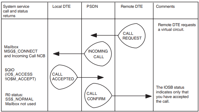
Figure 3.5, ''Accept a Request to Set Up a Virtual'' shows how a request to set up a virtual circuit is accepted.
3.2.4. Rejecting an Incoming X.25 Call Request
Use the $QIO(IO$_ACCESS!IO$M_ABORT) operation to reject a request to set up a virtual circuit. If you subscribe to the fast select acceptance facility, IO$_ ACCESS!IO$M_ABORT also offers you the option of returning data to the calling DTE.
You are advised to use the NCB received as part of the incoming call as an argument to this $QIO. Find the NCB in the mailbox associated with the channel which received the call.
If the incoming call specifies fast select with or without restriction on response, and you wish to reply with some data, add a response data field (PSI$C_NCB_ RESPDATA) to the NCB.
You can specify a diagnostic code field (PSI$C_NCB_DIAGCODE) to contain user-specified codes that show reasons for the rejection.
You can also specify or modify local facilities by adding a local facilities field (PSI$C_NCB_LOCFACR) to the NCB.
You may modify the called address extension facility (PSI$C_NCB_CALLED_ EXTENSION) in the NCB.
If you create a new NCB to reject the call, always copy the incoming call identification field (PSI$C_NCB_ICI) from the received NCB.
The operation completes when X.25 for OpenVMS sends the rejection to the remote DTE.
Figure 3.6, ''Reject a Request to Set Up a Virtual Circuit'' shows how a request to set up a virtual circuit is rejected.
3.2.5. Redirecting an Incoming X.25 Call Request
Use the $QIO(IO$_ACCESS!IO$M_REDIRECT) operation to redirect a request to set up a virtual circuit to another process, before the request is accepted or rejected. $QIO(IO$_ACCESS!IO$M_REDIRECT) uses the fields, specified in the NCB in the normal way, to associate the request with a new process.
You are advised to use the NCB received as part of the incoming call as an argument to this $QIO. Find the NCB in the mailbox associated with the channel which received the call. You can modify the following fields in the NCB or add them if they are not present in the original call:
Local subaddress (PSI$C_NCB_LOCSUBADR)
User data (PSI$C_NCB_USERDATA)
Called address extension (PSI$C_NCB_CALLED_EXTENSION)
Call redirection original address (PSI$C_NCB_CALL_REDIR_ORIG)
Call redirection reason (PSI$C_NCB_CALL_REDIR_RSN)
You may add the following fields:
Filter name (PSI$C_NCB_FILTER)
Redirect priority (PSI$C_NCB_FLT_REDPRI)
Note
If you use PSI$C_NCB_FILTER, PSI$C_NCB_FLT_REDPRI is ignored.
Do not modify the incoming call identification field.
If you create a new NCB to redirect the call, X.25 for OpenVMS copies all fields not specified in the new NCB from the received NCB.
This $QIO allows you to write a process to receive some, or all, of the requests to set up a virtual circuit, and to redirect these requests to other processes using your own algorithms.
To redirect the request, you must return the NCB to the incoming call handler after doing at least one of the following:
Add a filter name field to the NCB.
Add a redirect priority field to the NCB.
Always pass on the incoming call identification information.
The redirect priority causes X.25 for OpenVMS to exclude filters that have a priority greater than or equal to the redirect priority. For example, you could change the filter priority item in the received NCB to the redirect priority and use the same NCB in the redirect request. The destination search would effectively restart after your destination and continue down the priority order.
The operation completes when X.25 for OpenVMS redirects the call.
3.3. Transmitting and Receiving Data in an X.25 Program
Both the local DTE and the remote DTE can send and receive data. To do this, the local DTE and the remote DTE must have a protocol which signals:
When the DTE is starting to send data. To do this, the DTE sends messages with an IO$_WRITEVBLK operation.
When data transfer has finished.
When the data transfer has ended, one of the two DTEs must clear the virtual circuit. It is advisable that the receiving DTE and not the sending DTE should clear the circuit because data transmitted, but not yet received by the receiving DTE, may otherwise be lost when the circuit is cleared. For details on clearing a call, refer to Section 3.1.5, ''Clearing a Call''.
3.3.1. Transmitting Data
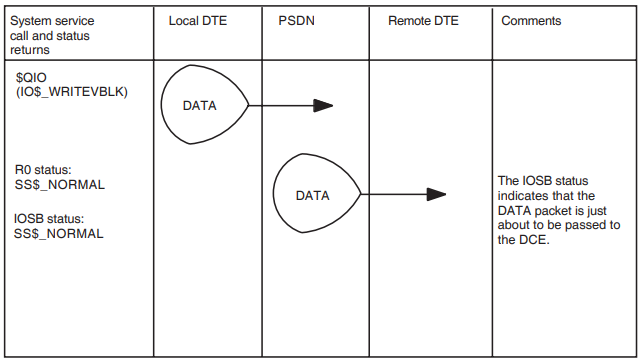
To send data over a virtual circuit, use the $QIO(IO$_WRITEVBLK) operation.
For full details of $QIO(IO$_WRITEVBLK), refer to the VSI X.25 for OpenVMS Programming Reference manual. Figure 3.7, ''Transmit Data'' shows how data is transmitted over a virtual circuit.
3.3.2. Receiving Data
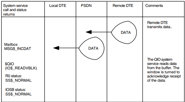
To receive data transmitted from a remote DTE, use the $QIO(IO$_READVBLK) operation.
When a packet of data arrives, the NW device does one of the following:
If a $QIO(IO$_READVBLK) system service has been issued, the NW device transfers the packet into the user’s buffer.
If a $QIO(IO$_READVBLK) system service has not been issued, the NW device will place a message in the mailbox. The message code is MSG$_ INCDAT, and this indicates that there is a packet of data waiting to be read.
Note that receiving a MSG$_INCDAT message does not guarantee that there is data to be read. Depending on the structure of the application, there may be none, one or many packets waiting, at the time the application processes the MSG$_INCDAT message.
There may be no packets waiting to be read if the application read data before it processed the MSG$_INCDAT message.
If more than one packet arrives, it will take more than one read to receive all the data.
For full details of $QIO(IO$_READVBLK), refer to the VSI X.25 for OpenVMS Programming Reference manual. Figure 3.8, ''Receive Data'' shows how data is received.
3.4. Transmitting and Confirming Receipt of Interrupts
An interrupt is a message which passes between DTEs outside the normal flow of data messages. You use system services to handle interrupts for X.25 programs. In X.29 programs, interrupts are handled by the NV device. Section 6.2, ''Setting NV Actions for Interrupt and Indication-of-Break'' describes how to control the interrupt action for the NV device.
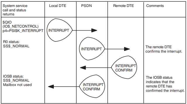
To transmit an interrupt, use the IO$_NETCONTROL operation with a parameter of PSI$K_INTERRUPT.
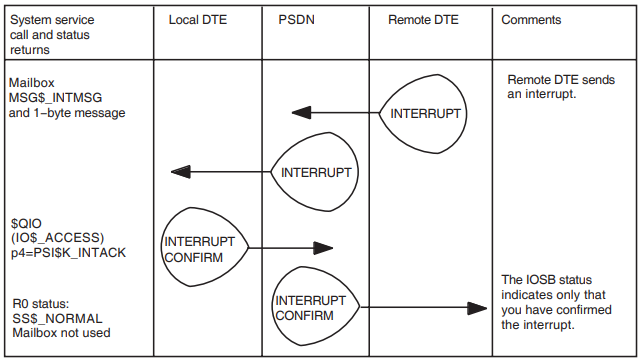
Figure 3.9, ''Transmit an Interrupt'' shows the transmission of an interrupt.
To confirm receipt of interrupts, use the IO$_NETCONTROL operation with a parameter of PSI$K_INTACK.
Figure 3.10, ''Confirm Receipt of an Interrupt'' shows the confirmation of an interrupt.
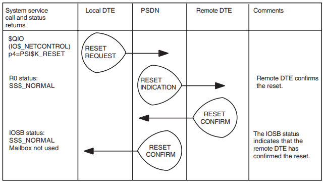
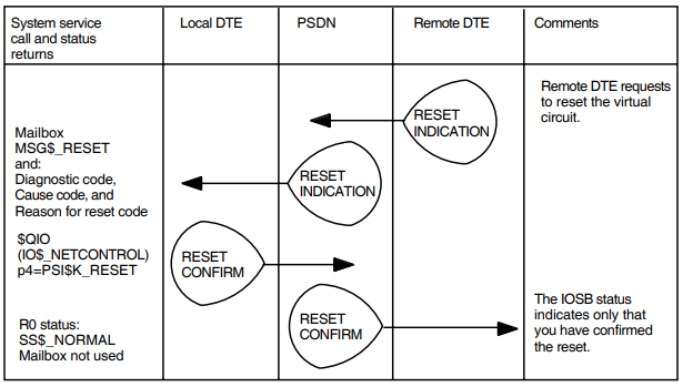
3.5. Resetting a Virtual Circuit and Confirming a Reset
In X.25 programs, you use the IO$_NETCONTROL call, with a parameter of PSI$K_RESET, to reset a virtual circuit and confirm receipt of a reset request.
The call resets the virtual circuit to its initial conditions (and all pending messages are discarded) or confirms receipt of a reset.
Note that a return status of SS$_NORMAL does not guarantee that the remote DTE receives the diagnostic code. Reception of the diagnostic code may be prevented if a collision of resets occurs within the network.
Figure 3.11, ''Reset a Virtual Circuit'' shows a virtual circuit being reset, and Figure 3.13, ''Confirm the Receipt of a Reset'' shows the confirmation of a reset.
3.6. Confirming Receipt of a Restart
In X.25 programs, you can confirm the receipt of a restart on a PVC, by using the IO$_NETCONTROL call, with a parameter of PSI$K_RESTART.
When a restart is received from the PSDN, all interrupts and resets are considered to have been acknowledged, all SVCs are cleared and all PVCs are restarted.
The restart is indicated by the message MSG$_PATHLOST in the mailbox and you acknowledge the restart with the IO$_NETCONTROL operation.
When the link to the other end breaks, the MSG$_PATHLOST message is placed in the mailbox:
When the link goes down.
When (and if) the link comes back up. This is when the PVC is usable again.
3.7. Handling Accepted X.29 Calls
An X.29 program can either handle the incoming call itself or start the login sequence.
To enable the X.29 terminal to log on, issue:
$QIO(IO$_NETCONTROL,PSI$K_X29_SET, PSI$K_X29_TEMP_NOHANG)
to disable temporarily the terminal characteristic /HANGUP.
$QIO(IO$_SETMODE) to ensure that typeahead is on.
$DASSGN to deassign the data channel to the NV driver.
To handle the call yourself, issue $QIOs to the NV device as described in the OpenVMS terminal driver documentation.
Interrupts and resets are handled by the NV device, and do not require intervention by a user program.
3.8. Transferring NV Devices Between Processes
To pass control to another process, you must coordinate the transfer of control; for example, by using a mailbox to transfer information between the two processes.
Suppose that process A accepted the call, control of which is to be passed to process B. The sequence of operations is as follows:
Process A issues:
$QIO(IO$_SETCHAR) to set the terminal characteristic TT$M_ NOTYPEAHEAD permanently (physically). This stops the terminal being passed to OpenVMS LOGINOUT while it is not assigned to a particular process.
$QIO(IO$_NETCONTROL, PSI$K_X29_SET, PSI$K_X29_TEMP_NOHANG) to disable temporarily the terminal characteristic /HANGUP. This prevents $DASSGN from deleting the NV device.
$DASSGN to release the NV device from process A.
Process A tells process B to use the NV device (for example, by sending mailbox messages).
Process B issues:
$ASSIGN to assign the NV device to process B.
$QIO(IO$_SETCHAR) to clear the terminal characteristic TT$M_ NOTYPEAHEAD permanently (physically), or $QIO(IO$_SETMODE) to clear TT$M_NOTYPEAHEAD temporarily (logically).
Note
The NV device is protected by OpenVMS device security. This means that process B will need the appropriate privileges to use the terminal
For details of the terminal driver $QIOs, refer to the OpenVMS terminal driver documentation.
3.9. Using a Permanent Virtual Circuit
To use X.25 over a Permanent Virtual Circuit (PVC), initially assign a channel to the device NWA0: using the $ASSIGN system service (refer to Section 3.1.2, ''Assigning the Control and Data Channels'') and then access the circuit using $QIO(IO$_ACCESS) (refer to Section 3.1.4, ''Requesting a Virtual Circuit''). Specify the name of the PVC in the PSI$C_NCB_PVCNAM field of the NCB when using IO$_ACCESS. To set up a PVC requires certain system resources; these are the same as for SVCs (refer to Section 2.7, ''System Resources Required for a Virtual Circuit'').
Before transmitting or receiving data over a PVC, you are advised to reset the circuit using $QIO(IO$_NETCONTROL) (refer to Section 3.5, ''Resetting a Virtual Circuit and Confirming a Reset'') and wait for completion of the reset. You are also advised to set up some form of handshake procedure, depending on the application, so that both ends of the PVC are aware that the other is ready to transmit or receive data.
Transmit and receive data using $QIO(IO$_WRITEVBLK) and $QIO(IO$_READVBLK) (refer to Section 3.3, ''Transmitting and Receiving Data in an X.25 Program'') and transmit and confirm receipt of interrupts using $QIO(IO$_NETCONTROL) (refer to Section 3.4, ''Transmitting and Confirming Receipt of Interrupts'') as for SVCs.
When you finish transmitting and receiving data, deaccess the circuit using $QIO(IO$_DEACCESS) (refer to Section 3.1.5, ''Clearing a Call'') and deassign the channel using $DASSGN (refer to Section 3.1.5, ''Clearing a Call'') as for SVCs.
If at any time you receive MSG$_PATHLOST in the mailbox, this shows that a restart has taken place for the DTE, and that some data, interrupt data and resets could have been lost. Confirm this message using $QIO(IO$_ NETCONTROL) (refer to Section 3.6, ''Confirming Receipt of a Restart'') before making further use of the PVC.
If you receive MSG$_DISCON in the mailbox, this means that the DECnet logical link to the X.25 Connector node has been lost. To reconnect to the PVC, use $QIO(IO$_DEACCESS), followed by $QIO(IO$_ACCESS).
Chapter 4. Writing an X.25 Program
This chapter describes how to write X.25 programs to handle an incoming call and to make an outgoing call.
This chapter consists of three sections:
Section 4.1, ''Minimum Configuration Entities'', lists the configuration entities that must be defined before an incoming call can be received and an outgoing call can be made.
Section 4.2, ''Writing a Program to Handle an Incoming Call'', describes how to write a program to handle an incoming call.
Section 4.3, ''Writing a Program to Make an Outgoing Call'', describes how to write a program to make an outgoing call.
Example programs are provided in the SYS$EXAMPLES: directory and summarized in the VSI X.25 for OpenVMS Programming Reference manual.
4.1. Minimum Configuration Entities
A system needs to be configured correctly to make and receive calls. This section lists the configuration entities that must be created for incoming and outgoing calls.
Note that the entities listed can be defined using the configuration program provided in X.25 for OpenVMS or by issuing NCL commands directly.
X25 ACCESS
X25 ACCESS SECURITY DTE CLASS
X25 ACCESS SECURITY DTE CLASS REMOTE DTE
X25 ACCESS DTE CLASS
For Client systems:
X25 CLIENT
For Direct Connect systems:
The X25 ACCESS SECURITY DTE CLASS and X25 ACCESS SECURITY DTE CLASS REMOTE DTE entities are used to configure security on the system. Details on setting up system security are provided in the VSI X.25 for OpenVMS Security Guide.
The X25 CLIENT entity performs operations involved in receiving incoming calls from, and making calls to, a Connector system.
The entities listed for Direct Connect systems are used to configure a DTE. If you use the X.25 configuration program these entities will be created for you when you configure a DTE.
The X25 ACCESS DTE CLASS entity is used to group DTEs for a Direct Connect system. When you make an outgoing call you must specify a DTE Class for the outgoing call. The software will then select a DTE for the call. For a Client system, the DTE class specified points to one or more Connector systems that will make the outgoing call on behalf of the Client system.
4.1.1. Incoming Calls
To receive incoming calls, the following entities must be created in addition to those entities specified in Section 4.1, ''Minimum Configuration Entities''.
X25 ACCESS FILTER
X25 ACCESS SECURITY FILTER
The X25 ACCESS FILTER entity is used to determine which calls a process will handle. You do not need to create a static filter if dynamic filters are used. Details on static and dynamic filters are provided in the VSI X.25 for OpenVMS Management Guide.
The X25 ACCESS SECURITY FILTER entity is used with the SECURITY DTE CLASS and SECURITY DTE CLASS REMOTE DTE entities to provide security for incoming calls.
4.1.2. Outgoing Calls
To make an outgoing call, the X25 ACCESS TEMPLATE entity can be created in addition to those entities specified in Section 4.1, ''Minimum Configuration Entities''.
The X25 ACCESS TEMPLATE entity needs to be created only if you intend to use the specified template to make an outgoing call. A template does not need to be created to make an outgoing call, but creating a template is a convenient way of specifying the call parameters to be used for an outgoing call.
If a template is created, an X.25 application can reference the template and the call parameters set up in the template are used to make the outgoing call. You can therefore change call parameters without recompiling the X.25 application. For example, by placing the DTE address of the DTE to be called in the template you can change the address without recompiling the X.25 application. Details on creating templates are provided in the VSI X.25 for OpenVMS Management Guide.
4.2. Writing a Program to Handle an Incoming Call
In order to receive incoming X.25 calls, a program may be written either as a Network Process or as an X25 Access Application. A Network Processes is started manually, and registers itself as an X.25 listener, while an X25 Access Application is invoked by an X25 ACCESS APPLICATION entity each time an incoming call matches one of the X25 ACCESS APPLICATION entity’s filters.
4.2.1. Using a Network Process
Your program can declare itself to be a Network Process, and enter its own filters in the X25 Access module.
To receive incoming calls, an X.25 Network Process must direct X25 Access to listen on one or more filters, and specify a mailbox into which the incoming call notifications will be placed.
When an incoming call matches one of the filters, an NCB describing the call is placed in the mailbox. The Network Process can then read the NCB and accept, reject, or redirect the call.
The programming steps for writing a Network Process are:
Include the X.25 library
Include the X.25 library in any program you write. Section 2.2, ''Using the X.25 Library'' describes how to use the X.25 library.
Declare a Network Process Declaration Block
The Network Process Declaration Block (NPDB) is used to pass information to the X.25 for OpenVMS software.
Define this data structure, and its contents, in the appropriate place in your program (for example, at the head of the program in MACRO). The NPDB contains information defining the filters your program needs to use.
Create a mailbox and assign channels
You can either:
Issue the $CREMBX system service to create the mailbox, and then issue the $ASSIGN system service to associate the mailbox with the NW device and assign a control channel to that NW device.
Use the run-time library routine LIB$ASN_WTH_MBX to create a mailbox, assign a channel to the mailbox and assign a control channel to a new NW device.
For further information on creating mailboxes and assigning channels, refer to Section 3.1.1, ''Creating a Mailbox'' and Section 3.1.2, ''Assigning the Control and Data Channels'' respectively.
Declare a Network Process
Issue a $QIO(IO$_ACPCONTROL) system service request on the NW device created in step 3 to declare a Network Process.
In the Network Process Declaration Block (parameter p2), set the Access Level to ‘‘X25L3’’ and specify the required filter parameters. Refer to the VSI X.25 for OpenVMS Programming Reference manual for details of the IO$_ACPCONTROL function.
Read the Incoming Call NCB from the mailbox
Issue a $QIO(IO$_READVBLK) system service request on the mailbox created in step 3 to wait for an incoming call. (When an incoming X.25 call matches one of the filters specified in step 4, an NCB containing details of the call will be placed in the mailbox).
Refer to the VSI X.25 for OpenVMS Programming Reference manual for details of mailbox message and NCB formats.
Accept, Reject or Redirect the call
Your program can use the details contained in the incoming call NCB to decide whether to Accept, Reject (clear), or Redirect (match against another filter) the call.
To accept the call, perform one of the following actions:
To accept the call without negotiating facilities, issue a $QIO(IO$_ ACCESS!IO$M_ACCEPT) system service request on the NW channel, specifying the incoming call NCB (from step 5) as parameter p2.
To accept the call subject to negotiated facilities, create an NCB containing the Incoming Call Identifier (which can be obtained from the NCB read in step 5), and the required facilities. The required facilities can either be specified as individual item codes in the NCB or collectively in a template using the TEMPLATE item code. Issue a $QIO(IO$_ACCESS!IO$M_ACCEPT) system service request on the NW channel, specifying the new NCB as parameter p2.
For further information on accepting a call, refer to Section 3.2.3, ''Accepting an Incoming X.25 Call Request''. The VSI X.25 for OpenVMS Programming Reference manual describes how to specify facilities in an NCB.
To reject the call, issue a $QIO(IO$_ACCESS!IO$M_ABORT) system service request on the NW channel, specifying the incoming call NCB as parameter p2. For further information on rejecting a call, refer to Section 3.2.4, ''Rejecting an Incoming X.25 Call Request''.
To redirect the call, create an NCB containing the Incoming Call Identifier for the call (which can be obtained from the NCB read in step 5) and either the filter name or filter priority to be used when rematching the call. Issue a $QIO(IO$_ACCESS!IO$M_REDIRECT) system service request on the NW channel, specifying the new NCB as parameter p2. For further information on redirecting a call, refer to Section 3.2.5, ''Redirecting an Incoming X.25 Call Request''.
Receive and send data
When you have accepted the call, use the $QIO(IO$_READVBLK) system service on the NW channel to read incoming data.
Use $QIO(IO$_WRITEVBLK) to send data.
For further information on receiving and sending data, refer to Section 3.3, ''Transmitting and Receiving Data in an X.25 Program''.
Clear the virtual circuit
When you have finished sending your data, clear the virtual circuit by using the $QIO(IO$_DEACCESS) system service (refer to Section 3.1.5, ''Clearing a Call'' for further information on clearing the virtual circuit).
Deassign the channels
If you do not want to make another connection to a remote DTE then your program must deassign the mailbox and NWA0: channels it has been using by issuing a $DASSGN system service request (refer to Section 3.1.5, ''Clearing a Call'' for more information).
Note that it is the responsibility of the user program to confirm RESETS and INTERRUPTS. As RESETS may be received at any time, make sure that your application allows for this. For further information about confirming receipt of RESETS, refer to Section 3.5, ''Resetting a Virtual Circuit and Confirming a Reset''. For further information about confirming receipt of INTERRUPTS, refer to Section 3.4, ''Transmitting and Confirming Receipt of Interrupts''.
4.2.2. Using an Access Application
When X.25 for OpenVMS delivers an incoming call to an X.25 listener in the X25 ACCESS APPLICATION entity, it creates a mailbox, and places the NCB for the incoming call in the mailbox. Note that these actions are performed only if the maximum number of incoming call activations for the relevant application has not been reached or the Maximum Activations attribute of the APPLICATION entity has been set to zero. If the maximum number has been reached, the call will be cleared.
X.25 for OpenVMS then creates a process under the user name specified in the entry in the APPLICATION entity. This process runs the OpenVMS LOGINOUT image to verify the user name and password from the APPLICATION entity. If they are invalid, the call is cleared. If they are valid, X.25 for OpenVMS:
Equates SYS$NET to the mailbox containing the NCB.
Invokes the LOGIN.COM procedure (if it exists) for the account.
Starts the command procedure (filename.COM) specified in the APPLICATION entity’s File attribute.
Creates a log file named after the command procedure (filename.LOG) in SYS$LOGIN:.
The command procedure can execute DCL commands, and it can also run a program to accept, redirect, or reject the incoming call.
The programming steps for writing an Access Application are:
Include the X.25 library
Include the X.25 library in any program you write. Section 2.2, ''Using the X.25 Library'' describes how to use the X.25 library.
Assign a channel to mailbox ‘‘SYS$NET’’
When X.25 for OpenVMS invokes the application, the logical name SYS$NET references the mailbox from which the incoming call NCB may be read.
Use the $ASSIGN system service to assign a channel to SYS$NET. Note that $CREMBX should not be used to assign a channel to SYS$NET. $CREMBX does not recognize SYS$NET as an existing mailbox and will create a new mailbox if used.
Assign a control channel to the X.25 network device
Use the system service $ASSIGN to create a new NW device, and assign a channel to it.
Read the Incoming Call NCB from the mailbox
Issue a $QIO(IO$_READVBLK) system service request on the mailbox from step 2 to read the incoming call NCB.
Refer to the VSI X.25 for OpenVMS Programming Reference manual for details of mailbox message and NCB formats.
Accept, Reject, or Redirect the call
Your program can use the details contained in the incoming call NCB to decide whether to Accept, Reject (clear), or Redirect (match against another filter) the call.
To accept the call, perform one of the following actions:
To accept the call without negotiating facilities, issue a $QIO(IO$_ ACCESS!IO$M_ACCEPT) system service request on the NW channel, specifying the incoming call NCB (from step 4) as parameter p2.
To accept the call subject to negotiated facilities, create an NCB containing the Incoming Call Identifier (which can be obtained from the NCB read in step 4), and the required facilities. The required facilities can either be specified as individual item codes in the NCB or collectively in a template using the TEMPLATE item code. Issue a $QIO(IO$_ACCESS!IO$M_ACCEPT) system service request on the NW channel, specifying the new NCB as parameter p2.
For further information on accepting a call, refer to Section 3.2.3, ''Accepting an Incoming X.25 Call Request''. The VSI X.25 for OpenVMS Programming Reference manual describes how to specify facilities in an NCB.
To reject the call, issue a $QIO(IO$_ACCESS!IO$M_ABORT) system service request on the NW channel, specifying the incoming call NCB as parameter p2. For further information on rejecting a call, refer to Section 3.2.4, ''Rejecting an Incoming X.25 Call Request''.
To redirect the call, create an NCB containing the Incoming Call Identifier for the call (which can be obtained from the NCB read in step 4) and either the filter name or filter priority to be used when rematching the call. Issue a $QIO(IO$_ACCESS!IO$M_REDIRECT) system service request on the NW channel, specifying the new NCB as parameter p2. For further information on redirecting a call, refer to Section 3.2.5, ''Redirecting an Incoming X.25 Call Request''.
Receive and send data
When you have accepted the call, use the $QIO(IO$_READVBLK) system service on the NW channel to read incoming data.
Use $QIO(IO$_WRITEVBLK) to send data.
For further information on receiving and sending data, refer to Section 3.3, ''Transmitting and Receiving Data in an X.25 Program''.
Clear the virtual circuit
When you have finished sending your data, clear the virtual circuit by using the $QIO(IO$_DEACCESS) system service (refer to Section 3.1.5, ''Clearing a Call'' for further information on clearing the virtual circuit).
Deassign the channels
If you do not want to make another connection to a remote DTE then your program must deassign the mailbox and NWA0: channels it has been using by issuing a $DASSGN system service request (refer to Section 3.1.5, ''Clearing a Call'' for more information).
Note
You must define an X25 ACCESS APPLICATION entity for the application. The VSI X.25 for OpenVMS Management Guide describes how to define an X25 ACCESS APPLICATION entity.
Note that it is the responsibility of the user program to confirm RESETs and INTERRUPTs. As RESETs may be received at any time, make sure that your application allows for this. For further information about confirming receipt of RESETS, refer to Section 3.5, ''Resetting a Virtual Circuit and Confirming a Reset''. For further information about confirming receipt of INTERRUPTS, refer to Section 3.4, ''Transmitting and Confirming Receipt of Interrupts''.
4.3. Writing a Program to Make an Outgoing Call
A program to make an outgoing call comprises the following steps:
Include the X.25 library
Include the X.25 library in any program you write. Section 2.2, ''Using the X.25 Library'' describes how to use the X.25 library.
Declare the Network Connect Block
The Network Connect Block is used to pass information to the X.25 for OpenVMS software. Define this data structure, and its contents, in the appropriate place in your program (for example, at the head of the program in MACRO). The NCB is where you request optional facilities from the network, among other things (refer to Section 2.4, ''Data Structures'' for more details).
Create a mailbox and assign channels
Do one of the following:
Issue the $CREMBX system service to create the mailbox, and then issue the $ASSIGN system service to associate the mailbox with the NW device and assign a control channel to that NW device.
Use the run-time library routine, LIB$ASN_WTH_MBX to create a mailbox, assign a channel to the mailbox and assign a channel to the NW device.
For further information on creating a mailbox and assigning a channel, refer to Section 3.1.1, ''Creating a Mailbox'' and Section 3.1.2, ''Assigning the Control and Data Channels''.
Set up a virtual circuit
Set up a virtual circuit to the remote DTE using the NW channel you have just assigned. The $QIO(IO$_ACCESS) system service sets up the virtual circuit (refer to Section 3.1.4, ''Requesting a Virtual Circuit'' for further information on setting up virtual circuits).
Examine IOSB status returns
If the status returned is SS$_NORMAL, then the call has been accepted. If the status return is SS$_CLEARED, then the call has been rejected. Any other status indicates that the call was never made.
Read control messages from the mailbox
Queue an outstanding read on the mailbox created in step 3 so that you can receive control messages such as clears, interrupts, and resets.
To read mailbox data, issue a $QIO(IO$_READVBLK) system service request.
Send and receive data
To send data across the virtual circuit to a remote DTE, use the $QIO(IO$_WRITEVBLK) system service on the NW channel.
To receive data, issue $QIO(IO$_READVBLK).
For further information on sending and receiving data, refer to Section 3.3, ''Transmitting and Receiving Data in an X.25 Program''.
Clear the virtual circuit
When you have finished sending your data, clear the virtual circuit by using the $QIO(IO$_DEACCESS) system service (refer to Section 3.1.5, ''Clearing a Call'' for further information on clearing the virtual circuit).
Deassign the channels
If you do not want to make another connection to a remote DTE then your program must deassign the mailbox and NWA0: channels it has been using by issuing a $DASSGN system service request (refer to Section 3.1.5, ''Clearing a Call'' for more information).
Note that it is the responsibility of the user program to confirm RESETS and INTERRUPTS. As RESETS may be received at any time, make sure that your application allows for this. For further information about confirming receipt of RESETS, refer to Section 3.5, ''Resetting a Virtual Circuit and Confirming a Reset''. For further information about confirming receipt of INTERRUPTS, refer to Section 3.4, ''Transmitting and Confirming Receipt of Interrupts''.
Chapter 5. Writing an X.29 Program
This chapter describes how to write programs to handle an incoming call from a PAD, and to make an outgoing call to a remote PAD.
This chapter consists of two sections:
Section 5.1, ''Writing a Program to Handle an Incoming Call from a PAD'' describes how to write a program to handle an incoming call from a remote PAD.
Section 5.2, ''Writing a Program to Make an Outgoing Call to a Remote PAD'' describes how to make an outgoing call to a remote PAD.
Example programs are provided in the SYS$EXAMPLES: directory and summarized in the VSI X.25 for OpenVMS Programming Reference manual.
5.1. Writing a Program to Handle an Incoming Call from a PAD
An incoming X.29 call may be delivered to any of the following types of listener:
An X.25 listener represented by an X25 ACCESS APPLICATION entity. Section 5.1.1, ''X.25 Listener in the APPLICATION Entity'' describes how to write an X.29 program to handle an incoming call delivered to this type of listener.
An X.25 listener declared as a Network Process. Section 5.1.2, ''X.25 Listener Declared as a Network Process'' describes how to write an X.29 program to handle an incoming call delivered to this type of listener.
An X.29 listener represented by an X25 ACCESS APPLICATION entity. Section 5.1.3, ''X.29 Listener in the APPLICATION Entity'' describes how to write an X.29 program to handle an incoming call delivered to this type of listener.
The application can be one of two types:
- X29
- X29 login
If the application type is X29, an X.29 program is invoked to handle the call.
If the application type is X29 login, X.25 for OpenVMS starts the OpenVMS login sequence. In this case, an X.29 program is not required to handle the X.29 call.
An X.29 listener declared as a Network Process. Section 5.1.4, ''X.29 Listener Declared as a Network Process'' describes how to write a program to handle an incoming call delivered to this type of listener.
If the incoming call is not delivered to any of the above listeners, the call will be cleared.
5.1.1. X.25 Listener in the APPLICATION Entity
When X.25 for OpenVMS delivers an incoming call to an X.25 listener in the X25 ACCESS APPLICATION entity, it creates a mailbox, and places the NCB for the incoming call in the mailbox. Note that these actions are performed only if the maximum number of incoming call activations for the relevant application has not been reached or the Maximum Activations attribute of the APPLICATION entity has been set to zero. If the maximum number has been reached, the call will be cleared.
X.25 for OpenVMS then creates a process under the user name specified in the entry in the APPLICATION entity. This process runs the OpenVMS LOGINOUT image to verify the user name and password from the APPLICATION entity. If they are invalid, the call is cleared. If they are valid, X.25 for OpenVMS:
Equates SYS$NET to the mailbox containing the NCB.
Invokes the LOGIN.COM procedure (if it exists) for the account.
Starts the command procedure (filename.COM) specified in the APPLICATION entity’s File attribute.
Creates a log file named after the command procedure (filename.LOG) in SYS$LOGIN:.
The command procedure can execute DCL commands, and it can also run a program to accept, redirect, or reject the incoming call.
The programming steps are as follows:
Include the X.25 library
Include the X.25 library in any program you write. Section 2.2, ''Using the X.25 Library'' describes how to use the X.25 library.
Assign a control channel to the X.25 network device
Use the system service $ASSIGN to create a new NW device (NWAuu:), and assign a channel to it. Your X.29 program uses this channel as a control channel for the virtual circuit.
Assign a channel to the mailbox
When X.25 for OpenVMS invokes the application, the logical name SYS$NET references the mailbox from which the incoming call NCB may be read.
Use the $ASSIGN system service to assign a channel to SYS$NET. Note that $CREMBX should not be used to assign a channel to SYS$NET. $CREMBX does not recognize SYS$NET as an existing mailbox and will create a new mailbox if used.
Read the Incoming Call NCB from the mailbox
Issue a $QIO(IO$_READVBLK) system service request on the mailbox from step 3 to read the incoming call NCB.
Refer to the VSI X.25 for OpenVMS Programming Reference manual for details of mailbox message and NCB formats.
Accept, Reject, or Redirect the call
Your program can use the details contained in the incoming call NCB to decide whether to Accept, Reject (clear), or Redirect (match against another filter) the call.
To accept the call:
Use $ASSIGN to assign a channel to the NV device.
Use $GETDVI to discover the unit number uu of that device.
Use $QIO(IO$_ACCESS!IO$M_ACCEPT) on the control channel created in step 2, specifying the NCB, from step 4, as parameter p2, and the NV unit number as parameter p6.
In accepting the incoming call, your program may either allow the X.29 terminal to log on to the host OpenVMS system, or directly connect the X.29 terminal to an application process.
To reject the call, issue a $QIO(IO$_ACCESS!IO$M_ABORT) system service request on the control channel created in step 2, specifying the incoming call NCB, from step 4, as parameter p2.
To redirect the call, create an NCB containing the Incoming Call Identifier for the call (which can be obtained from the NCB read in step 4) and either the filter name or filter priority to be used when rematching the call. Use a $QIO(IO$_ACCESS!IO$M_REDIRECT) system service request on the NW channel, specifying the new NCB as parameter p2.
Interact with terminal
When the virtual circuit has been set up, your program can receive and transmit data by issuing QIOs to the NV device as described in the OpenVMS terminal driver documentation.
Clear the virtual circuit
You can clear the virtual circuit to the remote terminal either by using $DASSGN to deassign the last channel to the NV device, or explicitly by issuing a $QIO(IO$_DEACCESS) system service request.
Deassign the channels
If you do not want to make another connection to a remote DTE then your program must deassign the mailbox and NWAuu: channels it has been using by issuing a $DASSGN system service request (refer to Section 3.1.5, ''Clearing a Call'' for more information).
Note that interrupts and resets are handled by the NV device, and do not require intervention by a user program. For further details of how to use the system services, refer to Chapter 3, "Using System Services to Handle Calls".
5.1.2. X.25 Listener Declared as a Network Process
Your program can declare itself to be a Network Process, and enter its own filters in the X25 Access module.
To receive incoming calls, an X.25 Network Process must direct X25 Access to listen on one or more filters, and specify a mailbox into which the incoming call notifications will be placed.
When an incoming call matches one of the filters, an NCB describing the call is placed in the mailbox. The Network Process can then read the NCB and accept, reject, or redirect the call.
The programming steps are as follows:
Include the X.25 library
Include the X.25 library in any program you write. Section 2.2, ''Using the X.25 Library'' describes how to use the X.25 library.
Declare a Network Process Declaration Block
The Network Process Declaration Block (NPDB) is used to pass information to the X.25 for OpenVMS software.
Define this data structure, and its contents, in the appropriate place in your program (for example, at the head of the program in MACRO). The NPDB contains information defining the filters your program needs to use.
Create a mailbox and assign channels
Do one of the following:
Issue the $CREMBX system service to create the mailbox, and then issue the $ASSIGN system service to associate the mailbox with the NW device and assign a control channel to that NW device.
Use the run–time library routine LIB$ASN_WTH_MBX to create a mailbox, assign a channel to the mailbox and assign a control channel to the NW device.
For further information on creating a mailbox and assigning a channel, refer to Section 3.1.1, ''Creating a Mailbox'' and Section 3.1.2, ''Assigning the Control and Data Channels'' respectively.
Your X.29 program uses the channel to the NW device as a control channel for the virtual circuit.
Declare a network process
Issue a $QIO(IO$_ACPCONTROL) system service request on the NW device created in step 3 to declare a Network Process.
In the Network Process Declaration Block (parameter p2), set the Access Level to ‘‘X25L3’’ and specify the required filter parameters. Refer to the VSI X.25 for OpenVMS Programming Reference manual for details of the IO$_ACPCONTROL function.
Read the Incoming Call NCB from the mailbox
Issue a $QIO(IO$_READVBLK) system service request on the mailbox created in step 3 to wait for an incoming call. (When an incoming X.25 call matches one of the filters specified in step 4, an NCB containing details of the call will be placed in the mailbox).
Refer to the VSI X.25 for OpenVMS Programming Reference manual for details of mailbox message and NCB formats.
Accept, Reject, or Redirect the call
Your program can use the details contained in the incoming call NCB to decide whether to Accept, Reject (clear), or Redirect (match against another filter) the call.
To accept the call:
Use $ASSIGN to assign a channel to the NV device.
Use $GETDVI to discover the unit number uu of that device.
Use $QIO(IO$_ACCESS!IO$M_ACCEPT) on the control (NW) channel created in step 3, specifying the NCB, from step 5, as parameter p2, and the NV unit number as parameter p6. This system service invokes the X.29 protocol.
To reject the call, issue a $QIO(IO$_ACCESS!IO$M_ABORT) system service request on the control (NW) channel created in step 3, specifying the incoming call NCB, from step 5, as parameter p2.
To redirect the call, create an NCB containing the Incoming Call Identifier for the call (which can be obtained from the NCB read in step 5) and either the filter name or filter priority to be used when rematching the call. Use a $QIO(IO$_ACCESS!IO$M_REDIRECT) system service request on the control (NW) channel, specifying the new NCB as parameter p2.
Interact with terminal
When the virtual circuit has been set up, your program can issue QIOs to the NV device, as described in the OpenVMS terminal driver documentation.
Clear the virtual circuit
When you have finished sending your data, clear the virtual circuit by using the $QIO(IO$_DEACCESS) system service (refer to Section 3.1.5, ''Clearing a Call'' for further information on clearing the virtual circuit).
Deassign the channels
If you do not want to make another connection to a remote DTE then your program must deassign the mailbox and NWAuu: channels it has been using by issuing a $DASSGN system service request (refer to Section 3.1.5, ''Clearing a Call'' for more information).
Note that interrupts and resets are handled by the NV device, and do not require intervention by the user program.
5.1.3. X.29 Listener in the APPLICATION Entity
X.25 for OpenVMS accepts an incoming call when it delivers the call to an X.29 listener in the X25 ACCESS APPLICATION entity.
As the call has been accepted, your program cannot use the system service request $QIO(IO$_ACCESS!IO$M_REDIRECT) to redirect the call to another listener. However, your program may pass the NV device to another process (refer to Chapter 3, "Using System Services to Handle Calls").
X.25 for OpenVMS handles incoming calls as follows:
Creates an NV device.
Accepts the incoming call.
Creates a mailbox and places the NCB in the mailbox.
Equates SYS$NET to the mailbox containing the NCB.
Invokes (if it exists) the LOGIN.COM procedure for the account.
Starts the command procedure (filename.COM) specified in the APPLICATION entity of the listener.
Creates a log file named after the command procedure (filename.LOG) in SYS$LOGIN:.
The command procedure can execute DCL commands, and it can also run a program to handle the NV device. The programming steps are as follows:
Include the X.25 library
Include the X.25 library in any program you write. Section 2.2, ''Using the X.25 Library'' describes how to use the X.25 library.
Assign a control channel to the X.25 network device
Use the system service $ASSIGN to create a new NW device (NWAuu:), and assign a channel to it. Your X.29 program uses this channel as a control channel for the virtual circuit.
Assign a channel to the mailbox
When X.25 for OpenVMS invokes the application, the logical name SYS$NET references the mailbox from which the incoming call NCB may be read.
Use the $ASSIGN system service to assign a channel to SYS$NET. Note that $CREMBX should not be used to assign a channel to SYS$NET. $CREMBX does not recognize SYS$NET as an existing mailbox and will create a new mailbox if used.
Read the NCB and NV unit number from the mailbox
Issue $QIO(IO$_READVBLK) to read the NCB and the NV unit number from the mailbox. For details of $QIO(IO$_READVBLK), refer to the OpenVMS I/O documentation.
Assign a data channel
Use $ASSIGN to assign a channel to the NV device. To perform this action, convert the NV unit number to a device name string and then use $ASSIGN to assign a channel to the NV device.
If Typeahead is required, set the X.29 terminal to Typeahead
This will clear the TT$_NOTYPEAHEAD characteristic. Do this by issuing $QIO(IO$_SETMODE). For details of $QIO(IO$_SETMODE), refer to the OpenVMS system services documentation.
Interact with terminal
When the virtual circuit has been set up, your program can issue QIOs to the NV device, as described in the OpenVMS terminal driver documentation.
Clear the virtual circuit
You can clear the virtual circuit to the remote terminal either by using $DASSGN to deassign the channel to NV, or explicitly by using $QIO(IO$_ DEACCESS).
Deassign the channels
If you do not want to make another connection to a remote DTE then your program must deassign the mailbox and NWAuu: channels it has been using by issuing a $DASSGN system service request (refer to Section 3.1.5, ''Clearing a Call'' for more information).
Note that:
Interrupts and resets are handled by the NV device, and do not require intervention by a user program. Refer to Chapter 3, "Using System Services to Handle Calls" for further details of how to use the system services.
When the call is cleared, the NV device performs a hangup. This causes the NV device to go off line. Any further QIOs will fail with the status code SS$_DEVINACT. For an X.29 listener, this does not cause the process to be deleted. Your application must detect and handle hangups itself.
5.1.4. X.29 Listener Declared as a Network Process
Your program can enter its own filters in the X25 Access module by declaring itself to be a Network Process.
The programming steps are as follows:
Include the X.25 library
Include the X.25 library in any program you write. Section 2.2, ''Using the X.25 Library'' describes how to use the X.25 library.
Declare a Network Process Declaration Block
The Network Process Declaration Block (NPDB) is used to pass information to the X.25 for OpenVMS software.
Define this data structure, and its contents, in the appropriate place in your program (for example, at the head of the program in MACRO). The NPDB contains information defining the filters your program needs to use.
Create a mailbox and assign channels
Do one of the following:
Issue the $CREMBX system service to create the mailbox, and then issue $ASSIGN to associate the mailbox with the NW device and assign a control channel to that NW device.
Use the run–time library routine LIB$ASN_WTH_MBX to create a mailbox, assign a channel to the mailbox and assign a control channel to the NW device.
For further information on creating a mailbox and assigning a channel, refer to Section 3.1.1, ''Creating a Mailbox'' and Section 3.1.2, ''Assigning the Control and Data Channels''.
Your X.29 program uses the channel to the NW device as a control channel for the virtual circuit.
Declare a Network Process
Issue $QIO(IO$_ACPCONTROL) to declare a Network Process. In the Network Process Declaration Block (parameter p2), set the Access Level to ‘‘X29’’ and specify the required filter parameters. Refer to the VSI X.25 for OpenVMS Programming Reference manual for details on the IO$_ ACPCONTROL system service call.
Read the NCB and NV unit number from the mailbox
Issue $QIO(IO$_READVBLK) to read the NCB containing the NV unit number from the mailbox. (For details of the mailbox contents, refer to the VSI X.25 for OpenVMS Programming Reference manual. For details of $QIO(IO$_READVBLK), refer to the OpenVMS I/O documentation.) This QIO will complete when X.25 for OpenVMS has delivered an incoming call to your listener and written an NCB into the mailbox.
Assign a data channel
Use $ASSIGN to assign a data channel to NVAuu:. To perform this action, convert the NV unit number to a device name string and then use $ASSIGN to assign a channel to the NV device.
If Typeahead is required, set the X.29 terminal to Typeahead
This will clear the TT$_NOTYPEAHEAD characteristic. Do this by issuing $QIO(IO$_SETMODE). For details of $QIO(IO$_SETMODE), refer to the OpenVMS system services documentation.
Interact with terminal
As the virtual circuit has already been set up, your program can issue QIOs to the NV device, as described in the OpenVMS terminal driver documentation.
Clear the virtual circuit
You can clear the virtual circuit to the remote terminal either by using $DASSGN to deassign the channel to NV, or explicitly by using $QIO(IO$_ DEACCESS) through the NW control channel.
Deassign the channels
If you do not want to make another connection to a remote DTE then your program must deassign the mailbox and NWA0: channels it has been using by issuing a $DASSGN system service request (refer to Section 3.1.5, ''Clearing a Call'' for more information).
Remove the filters from the X25 Access module
To remove the filters from the X25 Access module, issue $DASSGN to deassign the channel to the NW device that was used to declare the Network Process.
Note that interrupts and resets are handled by the NV device, and do not require intervention by a user program. Refer to Chapter 3, "Using System Services to Handle Calls" for further details of how to use the system services.
5.1.5. How to Find the Remote DTE Address
To find the remote DTE address of the calling PAD, you can use either system services, or Digital Command Language (DCL):
Using system services, issue the call $GETDVI with the item DVI$_TT_ACCPORNAM.
Using DCL, issue the command:
$ WRITE SYS$OUTPUT F$GETDVI("TT","TT_ACCPORNAM")Either method returns the information in the form:
dte-class.remote-dte-address
where dte-class is the local DTE Class on which the call was received (truncated to 16 characters). For example:
SONNET.567890123456
5.2. Writing a Program to Make an Outgoing Call to a Remote PAD
You can use an X.29 program to make outgoing calls to a remote X.29 terminal if the remote terminal uses a PAD that is set up to receive incoming calls.
Your program can request a virtual circuit to a PAD at another DTE by issuing the system service $QIO(IO$_ACCESS). Note that to use the X.29 programming interface, the system service request should specify an NV device for the circuit. This is because your program controls the virtual circuit by issuing system services to the NW device associated with the control channel, and passes messages through the NV device associated with the data channel.
When the PAD accepts your call request, the program can either:
Process the call itself.
Pass the NV device to an application process (refer to Section 3.7, ''Handling Accepted X.29 Calls'').
Start the login sequence, so that the user at the X.29 terminal can log in (refer to Section 3.7, ''Handling Accepted X.29 Calls'').
5.2.1. Writing a Program to Make an Outgoing Call
The basic steps for writing an X.29 program to make an outgoing call to the PAD at a remote DTE are as follows:
Include the X.25 library
Include the X.25 library in any program you write. Section 2.2, ''Using the X.25 Library'' describes how to use the X.25 library.
Create a Network Connect Block (NCB)
The Network Connect Block is used to pass information to the X.25 for OpenVMS software. Define this data structure and its contents in the appropriate place in your program (for example, at the head of a program in MACRO). The NCB contains, among other things, requests for optional facilities.
Assign a data channel
Your program must assign a data channel to the NV device, and create an NVAuu: device, using the $ASSIGN system service.
Find the number of the NV device
Use the system service $GETDVI to discover the number, uu, of the NV device.
Assign a control channel
Use the system service $ASSIGN to create a new NW device and assign a channel to it. Your X.29 program uses this channel as a control channel for the virtual circuit. Note that a single NW device can be used by more than one NV device.
Set up a virtual circuit
Set up a virtual circuit to the remote DTE using the channel you have assigned to the NW device. Use the system service $QIO(IO$_ACCESS), supplying an NCB as parameter p2, and specifying the NV unit number as parameter p6.
Examine IOSB status returns
If the status returned is SS$_NORMAL, then the call has been accepted. If the status return is SS$_CLEARED, then the call has been rejected. Any other status indicates that the call was never made.
If the remote DTE accepts the request, your program should go through steps 8to 10. Otherwise, your program should perform step 10.
Interact with terminal
To interact with the terminal, your program can:
Pass control to another process (refer to Section 3.7, ''Handling Accepted X.29 Calls'').
Handle the NV device itself, by issuing QIOs to the NV device as described in the OpenVMS terminal driver documentation.
Clear the virtual circuit
When you have finished sending data, clear the virtual circuit by one of the following:
Use the $DASSGN system service to clear the last channel to NV.
Use $QIO(IO$_DEACCESS) on the NW control channel.
Deassign the channels
Finally, your program must deassign the data and control channels it has been using, with the $DASSGN system service. This deletes the NV and NW devices.
Chapter 6. Setting Characteristics of the PAD, the NV Device, and the X.29 Terminal
6.1. Setting PAD Parameters
You can tailor the behavior of the PAD to match the formatting and transmission requirements of the X.29 terminal. These requirements include definitions for such characteristics as:
Echo of characters typed at the terminal
Completion and forwarding of packets
Formatting and editing facilities
PAD characteristics are controlled by PAD parameters, which you can set. There are four ways to set PAD parameters:
Issue commands to the PAD during a PAD command session. The commands and their use are described in the VSI X.25 for OpenVMS Utilities Guide.
Issue the SET TERMINAL/X29/PARAMETERS command to change individual PAD parameters. This command and its parameters are described in the VSI X.25 for OpenVMS Utilities Guide.
Issue QIOs to set individual PAD parameters. Such parameters are described in this chapter and Chapter 3, "Using System Services to Handle Calls".
Issue SET TERMINAL/X29/TEMPLATE commands or QIOs to change PAD parameter templates. The SET TERMINAL/X29/TEMPLATE command is described in the VSI X.25 for OpenVMS Utilities Guide. The QIOs are described in the VSI X.25 for OpenVMS Programming Reference manual.
The PAD parameters themselves are described in the VSI X.25 for OpenVMS Programming Reference manual.
6.1.1. Setting PAD Interrupt and Break Actions
Your program can control the meaning of the control requests for Interrupt and for Indication-of-Break by setting PAD parameter 7 (break). Do this by issuing the system service $QIO(IO$_NETCONTROL,PSI$K_X29_SET) with subfunction PSI$K_X29_PAD_PARAMS. For details of this parameter, refer to the VSI X.25 for OpenVMS Programming Reference manual.
Table 6.1, ''PAD Interrupt and Indication-of-Break Messages'' summarizes the actions relevant to Interrupt and Indication-of-Break.
| PAD Parameter 7 | PAD Action |
|---|---|
| 0 | No action |
| 1 | Send Interrupt to the NV unit |
| 4 | Send Indication–of–Break to the NV unit |
| 5 | Send Interrupt, followed by Indication-of-Break |
| 16 | Discard output to X.29 terminal, and set PAD Parameter 8 (Discard output) |
| 21 | Send Interrupt, followed by Indication-of-Break to the NV unit. Discard output to X.29 terminal, and set PAD Parameter 8 (Discard output) |
Figure 6.1, ''Response to INTERRUPT, with PAD Parameter 7 Set to 1'', Figure 6.2, ''Response to INTERRUPT, with PAD Parameter 7 Set to 5'', and Figure 6.3, ''Response to INTERRUPT, with PAD Parameter 7 Set to 21'' show the action of the PAD and the NV device in response to INTERRUPT, with PAD parameter 7 set to 1, 5, and 21.
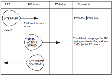
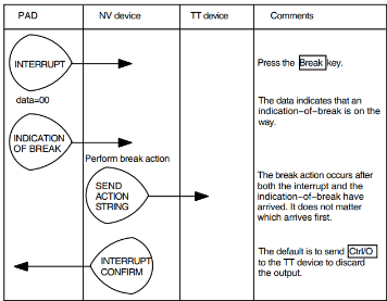
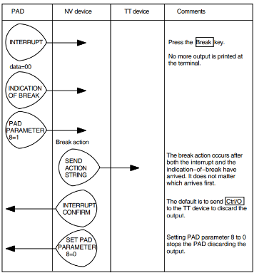
6.1.2. Setting Nonstandard PAD Parameters
To set nonstandard parameters, specify a sequence of PAD parameter items as follows:
| Item 1 |
PAD parameter code = 0 Parameter value = 0 |
| Item 2 |
Nonstandard PAD parameter code Parameter value |
| Item 3 |
Nonstandard PAD parameter code Parameter value |
...and so on.
For details of the nonstandard PAD facilities that are supported, refer to the technical documentation supplied by the PSDN.
6.2. Setting NV Actions for Interrupt and Indication-of-Break
The NV device usually queues data from the X.29 terminal in the order received. However, your program can define other actions when the NV device receives an Interrupt or an Indication-of-Break.
Your program can configure the NV device to take any combination of the following actions:
Purge all data in the receive buffer of the NV device (this is the default Interrupt action).
Purge all data in the transmit buffer of the NV device.
Reset the virtual circuit (note that this may cause some data to be lost).
Clear the call.
Pass an action string of data and/or control characters to the OpenVMS terminal driver, as though it had been entered from the X.29 terminal.
| Ctrl/X | Normally, this causes the OpenVMS terminal driver to purge its Typeahead buffer. |
| Ctrl/O | Normally, this causes the OpenVMS terminal driver to discard all the output currently being sent to the X.29 terminal. |
| Ctrl/Y | Normally, this causes the OpenVMS terminal driver to request the attention of the command language interpreter; for example, DCL. |
The type of information that may be sent in the action string includes:
You define NV device actions by entering action flags and an action string into a data structure called the NV Action Descriptor Block.
Action flags determine what action the NV device takes on receiving an Interrupt or Indication-of-Break.
The action string is sent to the OpenVMS terminal driver after the actions specified by the action flags have been performed. The action string passes data and/or control characters to the OpenVMS terminal driver.
Default Interrupt Action
The default Interrupt action is:
Purge the NV device receive buffer.
Send Ctrl/Y to the terminal driver to get the attention of DCL.
Modifying the Interrupt Action
To modify the Interrupt action:
Specify the actions for the NV device in the action flags of the NV Action Descriptor Block. Specify also the data to send to the OpenVMS terminal driver in the action strings of the NV Action Descriptor Block. For details of how to use the NV Action Descriptor Block, refer to Section 6.2.1, ''The NV Action Descriptor Block''.
Issue the $QIO(IO$_NETCONTROL,PSI$K_X29_SET) with the subfunction PSI$K_X29_INT_ACTION, to set the action flags and the action strings. You issue this QIO on the control channel to NW, specifying the NV device number as argument p6.
Default Break Action
The default Break action is:
Send Ctrl/O to the terminal driver to discard all the output in the transmit buffer.
Modifying the Break Action
To change the Break action:
Specify the actions for the NV device in the action flags of the NV Action Descriptor Block. Specify also the data to send to the OpenVMS terminal driver in the action strings of the NV Action Descriptor Block. For details of how to use the NV Action Descriptor Block, refer to Section 6.2.1, ''The NV Action Descriptor Block''.
Issue the $QIO(IO$_NETCONTROL,PSI$K_X29_SET) with the subfunction PSI$K_X29_BREAK_ACTION, to set the action flags and the action strings. You issue this QIO on the control channel to NW, specifying the NV device number as argument p6.
6.2.1. The NV Action Descriptor Block
The NV Action Descriptor Block is a data structure of between 4 and 20 bytes, comprising:
The action flags PSI$L_X29_ACTION_FLAGS (one longword)
The action string PSI$T_X29_ACTION_STRING (up to 15 bytes)
For symbolic programming, the start location of the action string is PSI$T_X29_ACTION_STRING, and the maximum length of the string is PSI$S_X29_ACTION_STRING.
The action flags occupy the first four bytes. They determine what action the NV driver should take on receiving an Interrupt or an Indication-of-Break. Only the first three bits of byte 0 are used, and these bits contain the following action flags:
| Bit 0 | PSI$V_X29_ACTION_RESET resets the virtual circuit. |
| Bit 1 | PSI$V_X29_ACTION_PURGE purges all input in the NV driver. Enter this action flag to ensure that the terminal driver processes the action string. |
| Bit 2 | PSI$V_X29_ACTION_CLEAR clears the call. The remainder of the Action flag longword must be zero. |
The action string PSI$T_X29_ACTION_STRING is a counted string of up to 15 bytes.
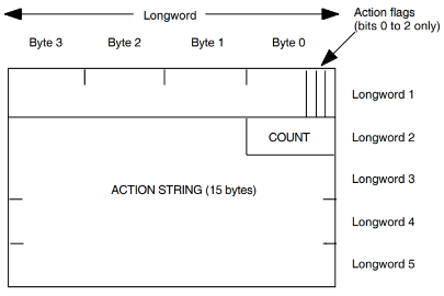
Figure 6.4, ''NV Action Descriptor Block'' illustrates the format of the NV Action Descriptor Block.
6.3. Setting X.29 Terminal Characteristics
You can use several SET TERMINAL commands to control the X.29
terminal. The following sections describe some of these commands.
6.3.1. Setting Echo Mode
The OpenVMS terminal driver can operate in either local-echo or host-echo mode. The OpenVMS system default is host-echo mode. However, the system default can be set to local-echo. Refer to the VSI X.25 for OpenVMS Utilities Guide for details of how to do this.
To set the OpenVMS echo mode, you can either use DCL commands, or issue QIOs.
To set the OpenVMS echo mode with DCL commands, use the command SET TERMINAL.
For local-echo mode, use the following command:
$ SET TERMINAL/LOCAL_ECHO
For host-echo mode, use the following command:
$ SET TERMINAL/NOLOCAL_ECHO
To set the OpenVMS terminal mode using QIOs, issue $QIO(IO$_SETMODE) to the NV device.
To select LOCAL_ECHO mode, set TT$M_NOECHO and TT2$M_LOCALECHO.
To select HOST_ECHO mode, clear TT$M_NOECHO and TT2$M_LOCALECHO.
To set the PAD echo mode, use the system service $QIO(PSI$K_X29_SET) with the subfunction PSI$K_X29_PAD_PARAMS.
Note that in host-echo mode, the user input is echoed by the OpenVMS terminal driver, and the PAD echo must be turned off. Otherwise, the user at the X.29 terminal sees each input character twice.
In local-echo mode, the PAD echoes the user data.
6.3.2. Setting 7-Bit ASCII and Parity
You can set up the OpenVMS terminal driver to communicate with systems which use 7-bit ASCII, by specifying 7-bit ASCII and even parity. To do this, use the following command:
$ SET TERMINAL/NOEIGHT/PARITY=EVEN
You can set up 7-bit ASCII and even parity as the system default. For details of how to do this, refer to the VSI X.25 for OpenVMS Utilities Guide.
Appendix A. Example of Parsing the Device Name String
The following program parses a device name string to extract the device unit number.
.title dev-unit - get the device unit number
$dvidef ; define DVI symbols
.macro itm3 buflen=4, itmcod, bufadr, retlen=0
.word buflen
.word itmcod
.address bufadr
.address retlen
.endm
tt: .ascid "tt"
chan: .blkw 1
unit_number: .blkl 1
phy_name_len: .blkl 1
phy_name: .blkb 64
dvi_list:
itm3 itmcod=dvi$_tt_phydevnam,-
buflen=64,-
bufadr=phy_name,-
retlen=phy_name_len
.long 0 ; end of the getdvi item list
;
; FAO variables
;
format: .ascid ~Device name: "!AD" Unit number: !SL~
buf: .blkb 80
bufdesc: .long bufdesc-buf
.address buf
.entry main,^m<>
;
; Assign a channel to the users terminal
;
$assign_s -
devnam = tt, chan = chan
blbc r0, exit
>
;
; Get the physical device name
;
$getdviw_s -
chan = chan, itmlst = dvi_list
blbc r0, exit
;
; Convert the unit number from the phydevnam into binary
;
pushab phy_name
pushl phy_name_len
calls #2, get_unit_number
movl r0, unit_number
;
; Display the result
;
$fao_s ctrstr = format, outbuf = bufdesc, outlen = bufdesc,-
p1 = phy_name_len, p2 = #phy_name,-
p3 = unit_number
blbc r0,
pushal bufdesc
calls #1, g^lib$put_output
exit: ret
;
; get_unit_number - return the unit number from the device name
; string
;
; This routine assumes that a device name is of the form
; <anything>...<non-digits>... <digits>... <non-digits>...
; This routine scans for the digits at the end of the device name.
; Typically this routine is passed a string like "_NVA213:"
;
; obtained from $GETDVI.
;
.entry get_unit_number, ^M<r2,r3,r4>
movl 8(ap), r2 ; pointer to device name
movzwl 4(ap), r3 ; length of the string
clrl r0 ; the unit number
10$:
decl r3 ; see if there is any string left
beql 40$ ; exit if not
movb (r2)[r3], r1 ; get byte from end of string
cmpb r1, #^A"0" ; see if its a digit
blssu 10$
cmpb r1, #^A"9"
bgtru 10$
>
;
; Found the last char that is a digit
;
movl r3, r4 ; remember the last
20$: decl r3
beql 40$
movb (r2)[r3], r1 ; get byte from end of string
cmpb r1, #^A"0" ; see if its a digit
blssu 30$ ; if not branch to convert code
cmpb r1, #^A"9"
blequ 20$ ; still a digit so scan further
30$: incl r3 ; offset to first digit
cmpl r3, r4
bgtr 40$
movzbl (r2)[r3], r1 ; get the digit
mull #10, r0 ; unit = unit * 10
movab -^A"0"(r1)[r0], r0 ; unit = unit + digit - "0"
brb 30$
40$:
; result is in R0
ret
On OpenVMS VAX systems, this library is also referred to as the VAX P.S.I. Library
Required only for devices that need microcode to be loaded.